1
Technical
Reference Guide
IR-700
EPSON
English
410356304
Rev.D
IR-700 Technical Reference Guide
CONFIDENTIALITY AGREEMENT
BY USING THIS DOCUMENT, YOU AGREE TO ABIDE BY THE TERMS OF THIS AGREEMENT. RETURN THIS
DOCUMENT IMMEDIATELY IF YOU DO NOT AGREE TO THESE TERMS.
❏
This document contains confidential, proprietary information of Seiko Epson Corporation or its affiliates. You
must keep such information confidential. If the user is a business entity or organization, you must limit disclosure
to your employees, agents, and contractors who have a need to know and who are also bound by obligations of
confidentiality.
❏
On the earlier of (a) termination of your relationship with Seiko Epson or (b) Seiko Epsonユs request, you
must stop using the confidential information. You must then return or destroy the information, as directed by
Seiko Epson.
❏
If a court, arbitrator, government agency, or the like orders you to disclose any confidential information, you must
immediately notify Seiko Epson. You agree to give Seiko Epson reasonable cooperation and assistance in resisting
disclosure.
❏
You may use confidential information only for the purpose of operating or servicing the products to which the
document relates, unless you obtain the prior written consent of Seiko Epson for some other use.
❏
Seiko Epson warrants that it has the right to disclose the confidential information. SEIKO EPSON MAKES NO
OTHER WARRANTIES CONCERNING THE CONFIDENTIAL INFORMATION OR ANY OTHER
INFORMATION IN THE DOCUMENT, INCLUDING (WITHOUT LIMITATION) ANY WARRANTY OF TITLE
OR NON-INFRINGEMENT. Seiko Epson has no liability for loss or damage arising from or relating to your use of
or reliance on the information in the document.
❏
You may not reproduce, store, or transmit the confidential information in any form or by any means (electronic,
mechanical, photocopying, recording, or otherwise) without the prior written permission of Seiko Epson.
❏
Your obligations under this Agreement are in addition to any other legal obligations. Seiko Epson does not waive
any right under this Agreement by failing to exercise it. The laws of Japan apply to this Agreement.
❏
This document shall apply only to the product(s) identified herein.
❏
No part of this document may be reproduced, stored in a retrieval system, or transmitted in any form or by any
means, electronic, mechanical, photocopying, recording, or otherwise, without the prior written permission of
Seiko Epson Corporation.
❏
The contents of this document are subject to change without notice. Contact us for the latest information.
❏
While every precaution has been taken in the preparation of this document, Seiko Epson Corporation assumes no
responsibility for errors or omissions.
❏
Neither is any liability assumed for damages resulting from the use of the information contained herein.
❏
Neither Seiko Epson Corporation nor its affiliates shall be liable to the purchaser of this product or third parties
for damages, losses, costs, or expenses incurred by the purchaser or third parties as a result of accident, misuse, or
abuse of this product or unauthorized modifications, repairs, or alterations to this product or (excluding the U.S.)
failure to strictly comply with Seiko Epson Corporation's operating and maintenance instructions.
❏
Seiko Epson Corporation shall not be liable against any damages or problems arising from the use of any options
or any consumable products other than those designated as Original EPSON Products or EPSON-Approved
Products by Seiko Epson Corporation.
CAUTIONS
©Seiko Epson Corporation, 2005.
Rev. D
i
TRADEMARKS
®
EPSON and ESC/POS are registered trademarks of Seiko Epson Corporation in the U.S. and other countries.
Intel® ,Celeron® and Pentium® are registered trademarks of Intel Corporation.
Microsoft®, MS-DOS® and Windows® are registered trademarks of Microsoft Corporation.
CompactFlash is a trademark of SanDisk Corporation.
General Notice: Other product and company names used herein are for identification purposes only and may be
trademarks of their respective companies.
ii
Rev. D
IR-700 Technical Reference Guide
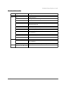
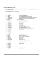
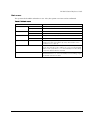
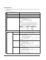
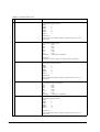
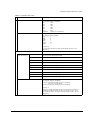
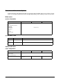
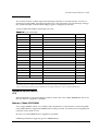
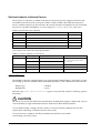
Revision Information
Revision
Page
Rev. A
Rev.B
Rev.C
Rev.D
Rev. D
Changed item and Contents
Newly established
1-5
Add the Interface.
1-6
Change the Software configuration.
1-7, 2-2, 6, 22, Chapter 7
Add the RAID event watch tool.
1-8, 2-2,
Add the Epson Remote Maintenance Software.
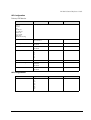
1-15,18 to 20
Add tne Dimension of the Customer Display, the Vertical stand, the
28KB and the MSR unit.
1-24
Add the specification of the DM-D120.
2-11 to 16, 24 to 29
Add the Dual Display settings.
2-34, 45, 46
Add the setting of power management.
2-49 to 51
Change the Setup procedure for Windows XP Professional Locally
Procured Edition.
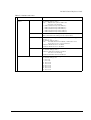
3-2, 50
Add the Dummy Cover
3-2, 51, 52
Add the Printer Tray
3-2, 62 to 66
Add the Powered USB board
2-1, 3-40
Add the note of handling the HDD.
2-48
Add the note about installation of Windows XP Professional Locally
Procured Edition.
3-49
Add the printer DIP switch setting when using the ERM.
1-3, 7, 21, 2-1, 32 -45, 74, 77
4-1, 2, 5-13, 15, 7-20, A-6, B-2
Add the Windows Embedded for Point of Service.
iii
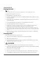
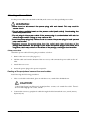
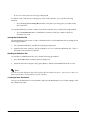
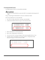
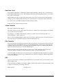
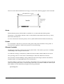
Key to Symbols
The symbols in this manual are identified by their level of importance, as defined below. Read
the following carefully before handling the product..
WARNING:
Provides information that must be followed carefully to avoid bodily injury.
CAUTION:
Provides information that must be observed to prevent damage to the equipment or
loss of data.
❏ Possibility of causing bodily injuries.
❏ Possibility of causing physical damage.
❏ Possibility of causing information loss.
Note:
Provides important information and useful tips on the operation of the equipment and the necessary
limitation matters to maintain the performance of the product,
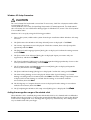
Precautions
WARNING:
❏ Turn off the power switch immediately and unplug the power cord if the IR-700 produces
smoke, a strange odor, or unusual noise.
Continued use may lead to fire or electric shock. Contact your dealer or an EPSON service
center for advice.
❏ Never disassemble or modify this product.
Tampering with this product may result in injury, fire or electric shock.
❏ For your own safety, never attempt to make repairs yourself.
❏ Do not disassemble or modify.
❏ Injury, fire, or electric shock may result.
❏ Do not insert or unplug the power plug with wet hands.
❏ Electric shock may result.
❏ Do not put foreign objects into or drop the product.
❏ Fire or electric shock may result.
❏ Turn off the IR-700 power switch immediately and unplug the power cord if a liquid such as
water gets inside, and contact your dealer or EPSON service center for advice.
iv
Rev. D
IR-700 Technical Reference Guide
WARNING
❏ Fire or electric shock may result.
❏ Plug it in to a household outlet by itself.
❏ Do not put many plugs into one outlet. Fire may result.
❏ Ensure easy access to the outlet so that the power plug can be unplugged immediately in an
emergency.
❏ Handle the power cord with care.
Fire or electric shock may result if the product is used in an improper manner.
•
Do not tamper with the power cord.
•
Do not put heavy objects on the power cord.
•
Do not bend, wrench, or pull it forcibly
•
Do not wire close to thermal appliances.
•
Do not plug in a power cable with foreign particles such as dust adhered to it.
•
Make sure to insert the power plug as far as it will go.
•
Replace the power cord if it is damaged.
❏ Regularly unplug the power plug from the outlet and clean up the ends and between the
blades.
•
If the power plug is plugged into the outlet over a long period, it gets dusty, and may
lead to fire due to a short.
❏ Do not disassemble, charge, deform, heat, or throw the built-in lithium battery into a fire.
•
Injuries due to bursting or chemical reaction may result.
❏ Do not obstruct the ventilation of the product.
If the ventilation is obstructed, heat is accumulated and fire may result.
•
Do not install it in a bookstand or the like which are narrow and poorly ventilated.
•
Do not place it on a carpet or blanket.
•
Do not cover it with a blanket, table cloth, or the like.
❏ Do not plug the telephone cable into the drawer kick out connector of the printer. Damage to
the telephone line or printer may result.
Rev. D
v
CAUTION
❏ When turning the power of IR-700 off once and turning it on again, wait at least 10 seconds
after turning it off before turning it on again.
•
Turning the power on immediately may result in abnormal booting.
❏ Handle the package with care during transport, unpacking, and when burning it.
•
Injury from cutting hands, etc. with the edge of the paper may result.
❏ Do not wire the various cables in any manner other than that specified in this manual.
•
Incorrect wiring may lead to malfunction or fire.
❏ Do not install the product in an unsteady place (unsteady table, tilted place, etc.).
•
Injury from dropping or toppling of the product may result.
❏ Do not install the product in a humid or dusty place.
•
A malfunction such as paper jam in the printer, fire, or electric shock may result.
❏ Do not use the product in places where flammable substances (gasoline, benzine, or thinner)
exist in the air.
•
Explosion or fire may result.
❏ Do not stand on this product or put heavy things on it.
•
Injury from toppling or breaking of the product may result.
❏ Avoid dropping, bumping, heavy vibration, or physical shock.
•
Injury and damage to the product may result from breaking the glass of the LCD.
❏ Do not use alcohol, benzine, thinner, trichloroethylene, or ketone solvent when removing
stains.
•
Deterioration or breakage of plastic and rubber parts may result.
❏ For safety, be sure to unplug the power plug if the product is not used over a long period.
❏ Do not connect to an AC power supply which is close to a device generating a power surge
or electrical noise. In particular, keep the product away from any device using a large motor.
•
Malfunction of IR-700 and POS system may result.
❏ Be sure to plug the power cable into the AC inlet of the product before plugging the power
plug into the outlet.
❏ Make sure to insert the power cable into the AC inlet of the product as far as it will go.
vi
Rev. D
IR-700 Technical Reference Guide
CAUTION
❏ Be sure to unplug the power cable from the outlet before unplugging it from the AC inlet of
the product.
❏
Unplug the power cable while holding the connector part. Do not unplug the power cable
by pulling the cable.
❏ Understand the product specifications (See [Power Specifications]).
❏ Do not short-circuit the connector pin when the power cable for the printer is connected to
the power connector for TM.
•
A short-circuit when the connecter is not connected to the printer may result because the
pins are exposed.
❏ Do not use the product other than with specified voltage.
•
Fire may result.
❏ Do not lift the product by holding the rear cover, the LCD, the POS keyboard, or MSR.
•
Injury from breaking or dropping the product may result.
❏ Avoid having the total power capacity of each device receiving power from the product
exceed the power capacity of the product.
•
Malfunction may result. See appendix regarding the power capacity.
❏ Be sure to use the product with the rear cover attached.
•
Using the product without the rear cover may cause fire or malfunction by allowing
foreign particles into the product.
❏ The printer is hot during or after use, and it could cause burns if you touch it. Let the head
cool before touching it.
❏ Be careful with the auto cutter found in the printer.
❏ Do not forcibly rotate or change the angle of the customer display.
•
Damage to the customer display or column may result.
❏ Do not use magnetic cards with the following abnormalities. Malfunction or serious
degradation in function may result.
•
Rev. D
Magnetic surface is dirty. Wet with water, etc. Foreign particles are adhered. Has chips
or breakage.
vii
Note
❏ Be sure to use DIMM, HDD, and CPU that we supplied or specified.
❏ Be sure to use an expanded board, the operation of which has been checked by us, to install
to the PCI slot. Contact your dealer for the operation check list. If a product other than those
on the list is used, it is your responsibility to sufficiently evaluate it.
❏ When a commercial application is installed, contact the dealer where you purchased the
product.
viii
Rev. D
IR-700 Technical Reference Guide
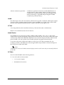
Regarding this Manual
Purpose of this Manual
This manual intends to provide necessary information for POS system development, design and
installation using IR-700 to engineers.
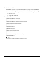
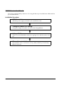
Contents of this Manual
The following list is a summary. All tables of contents are at the end of this section. Refer there
for more information and page numbers.
Composition of this manual is as follows.
Chapter 1 [IR-700 System Overview]
Describes features of IR-700, hardware
configuration, software configuration, part
names, etc.
Chapter 2 [OS Setup]
Describes the preinstalled OS (Windows 2000/
XP) and driver configuration and settings.
Chapter 3 [Hardware Setup]
Describes how to set up IR-700 and options.
Chapter 4 [Utilities]
Describes various utilities and setup
procedures.
Chapter 5 [BIOS Functions]
Describes BIOS setup and its settings.
Chapter 6 [DIAG Device Diagnostic
Program]
Describes functions and directions of DIAG
Device Diagnostic Program.
Chapter 7 [RAID]
Describes functions and directions of the RAID
system of IR-700.
Appendix A [Detailed Hardware
Specifications]
Describes the hardware specifications of IR-700.
Appendix B [Operating the Product
Continuously (24-hours/day)]
Describes the operating the product
continuously (24-hours/day) of IR-700.
Rev. D
ix
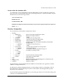
Related Manuals
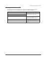
Related Manuals
x
Name
Comments
IR-700 User’s Manual
Describes the operation procedure.
IR-700 Service Manual
Describes the maintenance and repair procedure for IR-700 service
engineers.
Rev. D
IR-700 Technical Reference Guide
Contents
Revision Information . . . . . . . . . . . . . . . . . . . . . . . . . . . . . . . . . . . . . . . . . . . . . . . . . . . . . . . . . . . . . . . . . . . . .iii
Key to Symbols . . . . . . . . . . . . . . . . . . . . . . . . . . . . . . . . . . . . . . . . . . . . . . . . . . . . . . . . . . . . . . . . . . . . . . . . .iv
Precautions . . . . . . . . . . . . . . . . . . . . . . . . . . . . . . . . . . . . . . . . . . . . . . . . . . . . . . . . . . . . . . . . . . . . . . . . .iv
Regarding this Manual . . . . . . . . . . . . . . . . . . . . . . . . . . . . . . . . . . . . . . . . . . . . . . . . . . . . . . . . . . . . . . . . . . .ix
Purpose of this Manual . . . . . . . . . . . . . . . . . . . . . . . . . . . . . . . . . . . . . . . . . . . . . . . . . . . . . . . . . . . . . . . .ix
Contents of this Manual . . . . . . . . . . . . . . . . . . . . . . . . . . . . . . . . . . . . . . . . . . . . . . . . . . . . . . . . . . . . . . .ix
Related Manuals . . . . . . . . . . . . . . . . . . . . . . . . . . . . . . . . . . . . . . . . . . . . . . . . . . . . . . . . . . . . . . . . . . . . . . . .x
Contents . . . . . . . . . . . . . . . . . . . . . . . . . . . . . . . . . . . . . . . . . . . . . . . . . . . . . . . . . . . . . . . . . . . . . . . . . . . . . . .xi
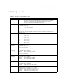
Chapter 1 IR-700 System Overview
IR-700 . . . . . . . . . . . . . . . . . . . . . . . . . . . . . . . . . . . . . . . . . . . . . . . . . . . . . . . . . . . . . . . . . . . . . . . . . . . . . . . . . .1-1
IR-700 Features . . . . . . . . . . . . . . . . . . . . . . . . . . . . . . . . . . . . . . . . . . . . . . . . . . . . . . . . . . . . . . . . . . . . . . . . . .1-2
Hardware . . . . . . . . . . . . . . . . . . . . . . . . . . . . . . . . . . . . . . . . . . . . . . . . . . . . . . . . . . . . . . . . . . . . . . . . . . . . . .1-4
Hardware configurations . . . . . . . . . . . . . . . . . . . . . . . . . . . . . . . . . . . . . . . . . . . . . . . . . . . . . . . . . . . . . .1-4
Difference between PC/AT PC and the IR-700 . . . . . . . . . . . . . . . . . . . . . . . . . . . . . . . . . . . . . . . . . . . .1-5
Interface . . . . . . . . . . . . . . . . . . . . . . . . . . . . . . . . . . . . . . . . . . . . . . . . . . . . . . . . . . . . . . . . . . . . . . . . . . .1-5
Software configuration . . . . . . . . . . . . . . . . . . . . . . . . . . . . . . . . . . . . . . . . . . . . . . . . . . . . . . . . . . . . . . . . . . .1-6
BIOS . . . . . . . . . . . . . . . . . . . . . . . . . . . . . . . . . . . . . . . . . . . . . . . . . . . . . . . . . . . . . . . . . . . . . . . . . . . . . . .1-6
Device diagnostic utility (DIAG) . . . . . . . . . . . . . . . . . . . . . . . . . . . . . . . . . . . . . . . . . . . . . . . . . . . . . . . .1-6
Operating system . . . . . . . . . . . . . . . . . . . . . . . . . . . . . . . . . . . . . . . . . . . . . . . . . . . . . . . . . . . . . . . . . . . .1-7
RAID BIOS/Config utility . . . . . . . . . . . . . . . . . . . . . . . . . . . . . . . . . . . . . . . . . . . . . . . . . . . . . . . . . . . . . . .1-7
GUI utility (RAID Utility for Windows) . . . . . . . . . . . . . . . . . . . . . . . . . . . . . . . . . . . . . . . . . . . . . . . . . . . . .1-7
RAID Event Watch tool . . . . . . . . . . . . . . . . . . . . . . . . . . . . . . . . . . . . . . . . . . . . . . . . . . . . . . . . . . . . . . . .1-7
POS controller . . . . . . . . . . . . . . . . . . . . . . . . . . . . . . . . . . . . . . . . . . . . . . . . . . . . . . . . . . . . . . . . . . . . . . .1-7
OLE-POS . . . . . . . . . . . . . . . . . . . . . . . . . . . . . . . . . . . . . . . . . . . . . . . . . . . . . . . . . . . . . . . . . . . . . . . . . . . .1-8
Printer driver-APD . . . . . . . . . . . . . . . . . . . . . . . . . . . . . . . . . . . . . . . . . . . . . . . . . . . . . . . . . . . . . . . . . . . .1-8
Epson Remote Maintenance Software . . . . . . . . . . . . . . . . . . . . . . . . . . . . . . . . . . . . . . . . . . . . . . . . . .1-8
Options . . . . . . . . . . . . . . . . . . . . . . . . . . . . . . . . . . . . . . . . . . . . . . . . . . . . . . . . . . . . . . . . . . . . . . . . . . . . .1-9
Operation Testing Products for IR . . . . . . . . . . . . . . . . . . . . . . . . . . . . . . . . . . . . . . . . . . . . . . . . . . . . . . . . . . .1-9
Part Names . . . . . . . . . . . . . . . . . . . . . . . . . . . . . . . . . . . . . . . . . . . . . . . . . . . . . . . . . . . . . . . . . . . . . . . . . . . . .1-10
Jumper Locations and Settings . . . . . . . . . . . . . . . . . . . . . . . . . . . . . . . . . . . . . . . . . . . . . . . . . . . . . . . . . . . .1-14
Main board jumpers . . . . . . . . . . . . . . . . . . . . . . . . . . . . . . . . . . . . . . . . . . . . . . . . . . . . . . . . . . . . . . . . . .1-14
IR-700 operation . . . . . . . . . . . . . . . . . . . . . . . . . . . . . . . . . . . . . . . . . . . . . . . . . . . . . . . . . . . . . . . . . . . . . . . . .1-14
Movable Range of the Customer Display . . . . . . . . . . . . . . . . . . . . . . . . . . . . . . . . . . . . . . . . . . . . . . . . . . .1-15
Dimensions . . . . . . . . . . . . . . . . . . . . . . . . . . . . . . . . . . . . . . . . . . . . . . . . . . . . . . . . . . . . . . . . . . . . . . . . . . . . .1-16
Specifications . . . . . . . . . . . . . . . . . . . . . . . . . . . . . . . . . . . . . . . . . . . . . . . . . . . . . . . . . . . . . . . . . . . . . . . . . . .1-21
IR-700 . . . . . . . . . . . . . . . . . . . . . . . . . . . . . . . . . . . . . . . . . . . . . . . . . . . . . . . . . . . . . . . . . . . . . . . . . . . . . .1-21
LCD . . . . . . . . . . . . . . . . . . . . . . . . . . . . . . . . . . . . . . . . . . . . . . . . . . . . . . . . . . . . . . . . . . . . . . . . . . . . . . . .1-22
Printer TM-T88IIIX . . . . . . . . . . . . . . . . . . . . . . . . . . . . . . . . . . . . . . . . . . . . . . . . . . . . . . . . . . . . . . . . . . . . .1-23
28 POS Keyboard DM-KX028 . . . . . . . . . . . . . . . . . . . . . . . . . . . . . . . . . . . . . . . . . . . . . . . . . . . . . . . . . . .1-24
60 POS Keyboard DM-KX060 . . . . . . . . . . . . . . . . . . . . . . . . . . . . . . . . . . . . . . . . . . . . . . . . . . . . . . . . . . .1-24
MSR Unit DM-MX123 . . . . . . . . . . . . . . . . . . . . . . . . . . . . . . . . . . . . . . . . . . . . . . . . . . . . . . . . . . . . . . . . . .1-24
Customer Display Unit DM-D120 . . . . . . . . . . . . . . . . . . . . . . . . . . . . . . . . . . . . . . . . . . . . . . . . . . . . . . . .1-24
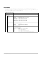
Chapter 2 OS and Drivers
Outline of This Chapter . . . . . . . . . . . . . . . . . . . . . . . . . . . . . . . . . . . . . . . . . . . . . . . . . . . . . . . . . . . . . . . . . .
Operating Systems . . . . . . . . . . . . . . . . . . . . . . . . . . . . . . . . . . . . . . . . . . . . . . . . . . . . . . . . . . . . . . . . . .
Drivers and Utilities . . . . . . . . . . . . . . . . . . . . . . . . . . . . . . . . . . . . . . . . . . . . . . . . . . . . . . . . . . . . . . . . . .
Windows 2000 Pre-Installed Model . . . . . . . . . . . . . . . . . . . . . . . . . . . . . . . . . . . . . . . . . . . . . . . . . . . . . . . .
Installation Procedure . . . . . . . . . . . . . . . . . . . . . . . . . . . . . . . . . . . . . . . . . . . . . . . . . . . . . . . . . . . . . . .
Directory Configuration . . . . . . . . . . . . . . . . . . . . . . . . . . . . . . . . . . . . . . . . . . . . . . . . . . . . . . . . . . . . . .
Windows 2000 Setup Procedure . . . . . . . . . . . . . . . . . . . . . . . . . . . . . . . . . . . . . . . . . . . . . . . . . . . . . . .
Setting the recognition range of the double click . . . . . . . . . . . . . . . . . . . . . . . . . . . . . . . . . . . . . . . .
Rev. D
2-1
2-1
2-1
2-4
2-4
2-6
2-7
2-8
xi
Various Configurations (Windows 2000) . . . . . . . . . . . . . . . . . . . . . . . . . . . . . . . . . . . . . . . . . . . . . . . . . . . . 2-8
Setting the Network . . . . . . . . . . . . . . . . . . . . . . . . . . . . . . . . . . . . . . . . . . . . . . . . . . . . . . . . . . . . . . . . . 2-8
EPSON Serial Driver . . . . . . . . . . . . . . . . . . . . . . . . . . . . . . . . . . . . . . . . . . . . . . . . . . . . . . . . . . . . . . . . . . 2-10
Dual Display . . . . . . . . . . . . . . . . . . . . . . . . . . . . . . . . . . . . . . . . . . . . . . . . . . . . . . . . . . . . . . . . . . . . . . . 2-11
Adding Windows 2000 Applications . . . . . . . . . . . . . . . . . . . . . . . . . . . . . . . . . . . . . . . . . . . . . . . . . . . 2-15
Support Information . . . . . . . . . . . . . . . . . . . . . . . . . . . . . . . . . . . . . . . . . . . . . . . . . . . . . . . . . . . . . . . . . 2-16
Recovering the OS . . . . . . . . . . . . . . . . . . . . . . . . . . . . . . . . . . . . . . . . . . . . . . . . . . . . . . . . . . . . . . . . . . 2-17
Windows XP Pre-Installed Model . . . . . . . . . . . . . . . . . . . . . . . . . . . . . . . . . . . . . . . . . . . . . . . . . . . . . . . . . . 2-19
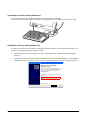
Installation Procedure . . . . . . . . . . . . . . . . . . . . . . . . . . . . . . . . . . . . . . . . . . . . . . . . . . . . . . . . . . . . . . . 2-19
Directory Configuration . . . . . . . . . . . . . . . . . . . . . . . . . . . . . . . . . . . . . . . . . . . . . . . . . . . . . . . . . . . . . . 2-21
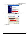
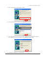
Windows XP Setup Procedure . . . . . . . . . . . . . . . . . . . . . . . . . . . . . . . . . . . . . . . . . . . . . . . . . . . . . . . . 2-22
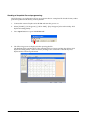
Setting the recognition range of the double click . . . . . . . . . . . . . . . . . . . . . . . . . . . . . . . . . . . . . . . . 2-22
Various Configurations (Windows 2000) . . . . . . . . . . . . . . . . . . . . . . . . . . . . . . . . . . . . . . . . . . . . . . . . . . . . 2-23
EPSON Serial Driver . . . . . . . . . . . . . . . . . . . . . . . . . . . . . . . . . . . . . . . . . . . . . . . . . . . . . . . . . . . . . . . . . . 2-23
Dual Display . . . . . . . . . . . . . . . . . . . . . . . . . . . . . . . . . . . . . . . . . . . . . . . . . . . . . . . . . . . . . . . . . . . . . . . 2-24
Adding Windows XP Applications . . . . . . . . . . . . . . . . . . . . . . . . . . . . . . . . . . . . . . . . . . . . . . . . . . . . . 2-28
Activation . . . . . . . . . . . . . . . . . . . . . . . . . . . . . . . . . . . . . . . . . . . . . . . . . . . . . . . . . . . . . . . . . . . . . . . . . 2-28
Recovering the OS . . . . . . . . . . . . . . . . . . . . . . . . . . . . . . . . . . . . . . . . . . . . . . . . . . . . . . . . . . . . . . . . . . 2-30
WEPOS Pre-Installed Model . . . . . . . . . . . . . . . . . . . . . . . . . . . . . . . . . . . . . . . . . . . . . . . . . . . . . . . . . . . . . . 2-32
Installation Procedure . . . . . . . . . . . . . . . . . . . . . . . . . . . . . . . . . . . . . . . . . . . . . . . . . . . . . . . . . . . . . . . 2-32
Directory Configuration . . . . . . . . . . . . . . . . . . . . . . . . . . . . . . . . . . . . . . . . . . . . . . . . . . . . . . . . . . . . . . 2-34
WEPOS Setup Procedure . . . . . . . . . . . . . . . . . . . . . . . . . . . . . . . . . . . . . . . . . . . . . . . . . . . . . . . . . . . . . 2-35
Setting the recognition range of the double click . . . . . . . . . . . . . . . . . . . . . . . . . . . . . . . . . . . . . . . . 2-35
Various Configurations (WEPOS) . . . . . . . . . . . . . . . . . . . . . . . . . . . . . . . . . . . . . . . . . . . . . . . . . . . . . . . . . . 2-36
Setting the Network . . . . . . . . . . . . . . . . . . . . . . . . . . . . . . . . . . . . . . . . . . . . . . . . . . . . . . . . . . . . . . . . . 2-36
Setting the FAX . . . . . . . . . . . . . . . . . . . . . . . . . . . . . . . . . . . . . . . . . . . . . . . . . . . . . . . . . . . . . . . . . . . . . 2-36
EPSON Serial Driver . . . . . . . . . . . . . . . . . . . . . . . . . . . . . . . . . . . . . . . . . . . . . . . . . . . . . . . . . . . . . . . . . . 2-37
Dual Display . . . . . . . . . . . . . . . . . . . . . . . . . . . . . . . . . . . . . . . . . . . . . . . . . . . . . . . . . . . . . . . . . . . . . . . 2-38
The addition and the deletion of the Windows component . . . . . . . . . . . . . . . . . . . . . . . . . . . . . . . 2-43
Using the command prompt at the full-screen . . . . . . . . . . . . . . . . . . . . . . . . . . . . . . . . . . . . . . . . . . 2-43
The device manager display . . . . . . . . . . . . . . . . . . . . . . . . . . . . . . . . . . . . . . . . . . . . . . . . . . . . . . . . . 2-43
Recovering the OS . . . . . . . . . . . . . . . . . . . . . . . . . . . . . . . . . . . . . . . . . . . . . . . . . . . . . . . . . . . . . . . . . . 2-44
Installation for Windows 2000 Professional Locally Procured Edition . . . . . . . . . . . . . . . . . . . . . . . . . . . . . 2-46
Installation Procedure . . . . . . . . . . . . . . . . . . . . . . . . . . . . . . . . . . . . . . . . . . . . . . . . . . . . . . . . . . . . . . . 2-46
Installing the Intel Chipset Diver . . . . . . . . . . . . . . . . . . . . . . . . . . . . . . . . . . . . . . . . . . . . . . . . . . . . . . . 2-49
Installing the VIDEO Driver . . . . . . . . . . . . . . . . . . . . . . . . . . . . . . . . . . . . . . . . . . . . . . . . . . . . . . . . . . . . 2-50
Installing the Network Driver . . . . . . . . . . . . . . . . . . . . . . . . . . . . . . . . . . . . . . . . . . . . . . . . . . . . . . . . . . 2-50
Installing the Sound Driver . . . . . . . . . . . . . . . . . . . . . . . . . . . . . . . . . . . . . . . . . . . . . . . . . . . . . . . . . . . . 2-51
Installing the POS Device Controller . . . . . . . . . . . . . . . . . . . . . . . . . . . . . . . . . . . . . . . . . . . . . . . . . . . . 2-51
Installing the Touch Panel Driver . . . . . . . . . . . . . . . . . . . . . . . . . . . . . . . . . . . . . . . . . . . . . . . . . . . . . . . 2-57
Setting the recognition range of the double click . . . . . . . . . . . . . . . . . . . . . . . . . . . . . . . . . . . . . . . . 2-57
Setting of Power management . . . . . . . . . . . . . . . . . . . . . . . . . . . . . . . . . . . . . . . . . . . . . . . . . . . . . . . 2-58
Installing the Serial Port Driver . . . . . . . . . . . . . . . . . . . . . . . . . . . . . . . . . . . . . . . . . . . . . . . . . . . . . . . . . 2-59
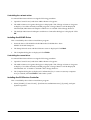
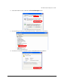
Installation for Windows XP Professional Locally Procured Edition . . . . . . . . . . . . . . . . . . . . . . . . . . . . . . 2-61
Installation Procedure . . . . . . . . . . . . . . . . . . . . . . . . . . . . . . . . . . . . . . . . . . . . . . . . . . . . . . . . . . . . . . . 2-62
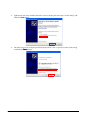
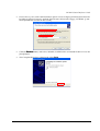
Installing the Intel Chipset Diver . . . . . . . . . . . . . . . . . . . . . . . . . . . . . . . . . . . . . . . . . . . . . . . . . . . . . . . 2-65
Installing the VIDEO Driver . . . . . . . . . . . . . . . . . . . . . . . . . . . . . . . . . . . . . . . . . . . . . . . . . . . . . . . . . . . . 2-66
Installing the Network Driver . . . . . . . . . . . . . . . . . . . . . . . . . . . . . . . . . . . . . . . . . . . . . . . . . . . . . . . . . . 2-66
Installing the SOUND Driver . . . . . . . . . . . . . . . . . . . . . . . . . . . . . . . . . . . . . . . . . . . . . . . . . . . . . . . . . . . 2-67
Installing the POS Device Controller . . . . . . . . . . . . . . . . . . . . . . . . . . . . . . . . . . . . . . . . . . . . . . . . . . . . 2-67
Installing the Touch Panel Driver . . . . . . . . . . . . . . . . . . . . . . . . . . . . . . . . . . . . . . . . . . . . . . . . . . . . . . . 2-72
Setting the recognition range of the double click . . . . . . . . . . . . . . . . . . . . . . . . . . . . . . . . . . . . . . . . 2-73
Installing the Serial Port Driver . . . . . . . . . . . . . . . . . . . . . . . . . . . . . . . . . . . . . . . . . . . . . . . . . . . . . . . . . 2-73
Activation . . . . . . . . . . . . . . . . . . . . . . . . . . . . . . . . . . . . . . . . . . . . . . . . . . . . . . . . . . . . . . . . . . . . . . . . . 2-74
HDD Power Down Timer Setting . . . . . . . . . . . . . . . . . . . . . . . . . . . . . . . . . . . . . . . . . . . . . . . . . . . . . . . . . . . 2-75
xii
Rev. D
IR-700 Technical Reference Guide
Chapter 3 Hardware Setup
Overview of the setup . . . . . . . . . . . . . . . . . . . . . . . . . . . . . . . . . . . . . . . . . . . . . . . . . . . . . . . . . . . . . . . . . . . 3-1
Precautions for Setting Up . . . . . . . . . . . . . . . . . . . . . . . . . . . . . . . . . . . . . . . . . . . . . . . . . . . . . . . . . . . . . . . . 3-2
How to Install Options/Peripheral Units . . . . . . . . . . . . . . . . . . . . . . . . . . . . . . . . . . . . . . . . . . . . . . . . . . . . .3-2
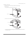
Rear cover . . . . . . . . . . . . . . . . . . . . . . . . . . . . . . . . . . . . . . . . . . . . . . . . . . . . . . . . . . . . . . . . . . . . . . . . . 3-3
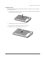
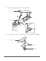
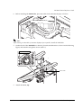
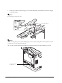
Setup of 28-key POSkeyboard (DM-KX028) . . . . . . . . . . . . . . . . . . . . . . . . . . . . . . . . . . . . . . . . . . . . . .3-4
Setup of MSR unit (DM-MX123) . . . . . . . . . . . . . . . . . . . . . . . . . . . . . . . . . . . . . . . . . . . . . . . . . . . . . . . .3-17
Setup of 60 key POS keyboard (DM-KX060) . . . . . . . . . . . . . . . . . . . . . . . . . . . . . . . . . . . . . . . . . . . . .3-22
Installation of HDD . . . . . . . . . . . . . . . . . . . . . . . . . . . . . . . . . . . . . . . . . . . . . . . . . . . . . . . . . . . . . . . . . .3-40
Main board unit . . . . . . . . . . . . . . . . . . . . . . . . . . . . . . . . . . . . . . . . . . . . . . . . . . . . . . . . . . . . . . . . . . . .3-43
DIMM . . . . . . . . . . . . . . . . . . . . . . . . . . . . . . . . . . . . . . . . . . . . . . . . . . . . . . . . . . . . . . . . . . . . . . . . . . . . .3-45
Printer unit . . . . . . . . . . . . . . . . . . . . . . . . . . . . . . . . . . . . . . . . . . . . . . . . . . . . . . . . . . . . . . . . . . . . . . . . . 3-46
Dummy Cover (OI-X02) . . . . . . . . . . . . . . . . . . . . . . . . . . . . . . . . . . . . . . . . . . . . . . . . . . . . . . . . . . . . . .3-50
Printer Tray (OI-X01) . . . . . . . . . . . . . . . . . . . . . . . . . . . . . . . . . . . . . . . . . . . . . . . . . . . . . . . . . . . . . . . . .3-51
Installing the customer display . . . . . . . . . . . . . . . . . . . . . . . . . . . . . . . . . . . . . . . . . . . . . . . . . . . . . . . .3-53
Set up of the Powered USB Board . . . . . . . . . . . . . . . . . . . . . . . . . . . . . . . . . . . . . . . . . . . . . . . . . . . . .3-62
Installing a PCI Card . . . . . . . . . . . . . . . . . . . . . . . . . . . . . . . . . . . . . . . . . . . . . . . . . . . . . . . . . . . . . . . . . 3-67
Installing a Cash Drawer . . . . . . . . . . . . . . . . . . . . . . . . . . . . . . . . . . . . . . . . . . . . . . . . . . . . . . . . . . . . . . . . . 3-69
Attaching a Power Cable . . . . . . . . . . . . . . . . . . . . . . . . . . . . . . . . . . . . . . . . . . . . . . . . . . . . . . . . . . . . . . . . 3-71
Routing of the peripheral connections and cables. . . . . . . . . . . . . . . . . . . . . . . . . . . . . . . . . . . . . . . 3-71
Installing Peripheral Devices to the COM Port . . . . . . . . . . . . . . . . . . . . . . . . . . . . . . . . . . . . . . . . . . . . . . . 3-72
Setup . . . . . . . . . . . . . . . . . . . . . . . . . . . . . . . . . . . . . . . . . . . . . . . . . . . . . . . . . . . . . . . . . . . . . . . . . . . . . 3-73
Chapter 4 Utility
Kinds of Utilities . . . . . . . . . . . . . . . . . . . . . . . . . . . . . . . . . . . . . . . . . . . . . . . . . . . . . . . . . . . . . . . . . . . . . . . . . 4-1
Obtaining Method of Each Utility . . . . . . . . . . . . . . . . . . . . . . . . . . . . . . . . . . . . . . . . . . . . . . . . . . . . . . . . . . 4-3
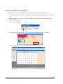
28-key Definition Utility . . . . . . . . . . . . . . . . . . . . . . . . . . . . . . . . . . . . . . . . . . . . . . . . . . . . . . . . . . . . . . . 4-4
MSR Setting Utility . . . . . . . . . . . . . . . . . . . . . . . . . . . . . . . . . . . . . . . . . . . . . . . . . . . . . . . . . . . . . . . . . . . 4-15
Definition Data Automatic Setting Utility (for Windows 2000/XP) . . . . . . . . . . . . . . . . . . . . . . . . . . . . 4-18
60-key Definition Utility . . . . . . . . . . . . . . . . . . . . . . . . . . . . . . . . . . . . . . . . . . . . . . . . . . . . . . . . . . . . . . . 4-19
Logon Tool (for Windows 2000) . . . . . . . . . . . . . . . . . . . . . . . . . . . . . . . . . . . . . . . . . . . . . . . . . . . . . . . . . . . 4-35
Installation . . . . . . . . . . . . . . . . . . . . . . . . . . . . . . . . . . . . . . . . . . . . . . . . . . . . . . . . . . . . . . . . . . . . . . . . . 4-35
How to Use . . . . . . . . . . . . . . . . . . . . . . . . . . . . . . . . . . . . . . . . . . . . . . . . . . . . . . . . . . . . . . . . . . . . . . . . . 4-35
Set up of the Touch Panel Driver, Install and Uninstall . . . . . . . . . . . . . . . . . . . . . . . . . . . . . . . . . . . . . 4-37
EPSON OPOS ADK . . . . . . . . . . . . . . . . . . . . . . . . . . . . . . . . . . . . . . . . . . . . . . . . . . . . . . . . . . . . . . . . . . . . . . 4-47
Creating the Component Software . . . . . . . . . . . . . . . . . . . . . . . . . . . . . . . . . . . . . . . . . . . . . . . . . . . . 4-48
Software Standardization . . . . . . . . . . . . . . . . . . . . . . . . . . . . . . . . . . . . . . . . . . . . . . . . . . . . . . . . . . . . 4-48
EPSON Software . . . . . . . . . . . . . . . . . . . . . . . . . . . . . . . . . . . . . . . . . . . . . . . . . . . . . . . . . . . . . . . . . . . . 4-48
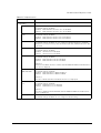
Chapter 5 BIOS Functions
BIOS Setup . . . . . . . . . . . . . . . . . . . . . . . . . . . . . . . . . . . . . . . . . . . . . . . . . . . . . . . . . . . . . . . . . . . . . . . . . . . . . . . . . . . . . 5-2
Operating Procedures . . . . . . . . . . . . . . . . . . . . . . . . . . . . . . . . . . . . . . . . . . . . . . . . . . . . . . . . . . . . . . . . . . . . . . . . 5-2
Screen Configuration of BIOS Setup Utility . . . . . . . . . . . . . . . . . . . . . . . . . . . . . . . . . . . . . . . . . . . . . . . . . . . . . 5-3
Saving settings . . . . . . . . . . . . . . . . . . . . . . . . . . . . . . . . . . . . . . . . . . . . . . . . . . . . . . . . . . . . . . . . . . . . . . . . . . . . . . 5-3
Boot Device Setting . . . . . . . . . . . . . . . . . . . . . . . . . . . . . . . . . . . . . . . . . . . . . . . . . . . . . . . . . . . . . . . . . . . . . . . . . . 5-3
BIOS Setup Main Menu . . . . . . . . . . . . . . . . . . . . . . . . . . . . . . . . . . . . . . . . . . . . . . . . . . . . . . . . . . . . . . . . . . . . . . 5-4
Main menu . . . . . . . . . . . . . . . . . . . . . . . . . . . . . . . . . . . . . . . . . . . . . . . . . . . . . . . . . . . . . . . . . . . . . . . . . . . . . . . . . 5-5
Advanced menu . . . . . . . . . . . . . . . . . . . . . . . . . . . . . . . . . . . . . . . . . . . . . . . . . . . . . . . . . . . . . . . . . . . . . . . . . . . . . 5-6
PnP/PCI Configurations Menu . . . . . . . . . . . . . . . . . . . . . . . . . . . . . . . . . . . . . . . . . . . . . . . . . . . . . . . . . . . . . . . . 5-15
Chipset menu . . . . . . . . . . . . . . . . . . . . . . . . . . . . . . . . . . . . . . . . . . . . . . . . . . . . . . . . . . . . . . . . . . . . . . . . . . . . . . . 5-16
Power menu . . . . . . . . . . . . . . . . . . . . . . . . . . . . . . . . . . . . . . . . . . . . . . . . . . . . . . . . . . . . . . . . . . . . . . . . . . . . . . . . 5-18
Boot menu . . . . . . . . . . . . . . . . . . . . . . . . . . . . . . . . . . . . . . . . . . . . . . . . . . . . . . . . . . . . . . . . . . . . . . . . . . . . . . . . . . 5-20
Security menu . . . . . . . . . . . . . . . . . . . . . . . . . . . . . . . . . . . . . . . . . . . . . . . . . . . . . . . . . . . . . . . . . . . . . . . . . . . . . . 5-22
Exit Menu . . . . . . . . . . . . . . . . . . . . . . . . . . . . . . . . . . . . . . . . . . . . . . . . . . . . . . . . . . . . . . . . . . . . . . . . . . . . . . . . . . 5-23
Rev. D
xiii
Defaults and Selectable Options . . . . . . . . . . . . . . . . . . . . . . . . . . . . . . . . . . . . . . . . . . . . . . . . . . . . . . . . . . . . . . . . . .
Main menu . . . . . . . . . . . . . . . . . . . . . . . . . . . . . . . . . . . . . . . . . . . . . . . . . . . . . . . . . . . . . . . . . . . . . . . . . . . . . . . .
Advanced menu . . . . . . . . . . . . . . . . . . . . . . . . . . . . . . . . . . . . . . . . . . . . . . . . . . . . . . . . . . . . . . . . . . . . . . . . . . . .
PCI/PnP Menu . . . . . . . . . . . . . . . . . . . . . . . . . . . . . . . . . . . . . . . . . . . . . . . . . . . . . . . . . . . . . . . . . . . . . . . . . . . . .
Chipset Menu . . . . . . . . . . . . . . . . . . . . . . . . . . . . . . . . . . . . . . . . . . . . . . . . . . . . . . . . . . . . . . . . . . . . . . . . . . . . . .
Power Menu . . . . . . . . . . . . . . . . . . . . . . . . . . . . . . . . . . . . . . . . . . . . . . . . . . . . . . . . . . . . . . . . . . . . . . . . . . . . . . .
Boot menu . . . . . . . . . . . . . . . . . . . . . . . . . . . . . . . . . . . . . . . . . . . . . . . . . . . . . . . . . . . . . . . . . . . . . . . . . . . . . . . . .
Security Menu . . . . . . . . . . . . . . . . . . . . . . . . . . . . . . . . . . . . . . . . . . . . . . . . . . . . . . . . . . . . . . . . . . . . . . . . . . . . . .
Exit Menu . . . . . . . . . . . . . . . . . . . . . . . . . . . . . . . . . . . . . . . . . . . . . . . . . . . . . . . . . . . . . . . . . . . . . . . . . . . . . . . . .
5-24
5-24
5-24
5-29
5-30
5-31
5-31
5-33
5-33
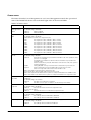
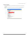
Chapter 6 Device Diagnostics Utility
Function . . . . . . . . . . . . . . . . . . . . . . . . . . . . . . . . . . . . . . . . . . . . . . . . . . . . . . . . . . . . . . . . . . . . . . . . . . . . . . 6-1
Devices Available for the DIAG . . . . . . . . . . . . . . . . . . . . . . . . . . . . . . . . . . . . . . . . . . . . . . . . . . . . . . . 6-1
Devices Not Available for the DIAG . . . . . . . . . . . . . . . . . . . . . . . . . . . . . . . . . . . . . . . . . . . . . . . . . . . 6-2
How to Do the DIAG Test . . . . . . . . . . . . . . . . . . . . . . . . . . . . . . . . . . . . . . . . . . . . . . . . . . . . . . . . . . . . . . . . 6-2
How to Start the DIAG . . . . . . . . . . . . . . . . . . . . . . . . . . . . . . . . . . . . . . . . . . . . . . . . . . . . . . . . . . . . . . . 6-2
How to Exit the DIAG . . . . . . . . . . . . . . . . . . . . . . . . . . . . . . . . . . . . . . . . . . . . . . . . . . . . . . . . . . . . . . . . 6-3
Using the Keyboard . . . . . . . . . . . . . . . . . . . . . . . . . . . . . . . . . . . . . . . . . . . . . . . . . . . . . . . . . . . . . . . . . 6-3
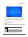
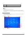
Explanation of the Screen . . . . . . . . . . . . . . . . . . . . . . . . . . . . . . . . . . . . . . . . . . . . . . . . . . . . . . . . . . . . . . . 6-4
Whole System Test and Individual Test . . . . . . . . . . . . . . . . . . . . . . . . . . . . . . . . . . . . . . . . . . . . . . . . . . . . . 6-10
Printing the Test Result . . . . . . . . . . . . . . . . . . . . . . . . . . . . . . . . . . . . . . . . . . . . . . . . . . . . . . . . . . . . . . . 6-10
Details of the Device Test . . . . . . . . . . . . . . . . . . . . . . . . . . . . . . . . . . . . . . . . . . . . . . . . . . . . . . . . . . . . . . . . 6-11
Chapter 7 How to Use RAID
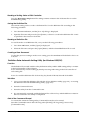
What is RAID? . . . . . . . . . . . . . . . . . . . . . . . . . . . . . . . . . . . . . . . . . . . . . . . . . . . . . . . . . . . . . . . . . . . . . . . . . . 7-2
Array Build . . . . . . . . . . . . . . . . . . . . . . . . . . . . . . . . . . . . . . . . . . . . . . . . . . . . . . . . . . . . . . . . . . . . . . . . . 7-3
RAID Status and Error Detection . . . . . . . . . . . . . . . . . . . . . . . . . . . . . . . . . . . . . . . . . . . . . . . . . . . . . . . 7-4
Checking the RAID Status . . . . . . . . . . . . . . . . . . . . . . . . . . . . . . . . . . . . . . . . . . . . . . . . . . . . . . . . . . . . 7-6
Windows Recognition . . . . . . . . . . . . . . . . . . . . . . . . . . . . . . . . . . . . . . . . . . . . . . . . . . . . . . . . . . . . . . . 7-7
IR-700 RAID System . . . . . . . . . . . . . . . . . . . . . . . . . . . . . . . . . . . . . . . . . . . . . . . . . . . . . . . . . . . . . . . . . . . . . 7-8
Settings before Use . . . . . . . . . . . . . . . . . . . . . . . . . . . . . . . . . . . . . . . . . . . . . . . . . . . . . . . . . . . . . . . . . . . . . 7-9
Array Build . . . . . . . . . . . . . . . . . . . . . . . . . . . . . . . . . . . . . . . . . . . . . . . . . . . . . . . . . . . . . . . . . . . . . . . . . 7-9
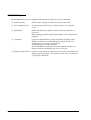
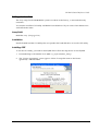
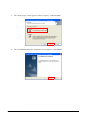
Installation . . . . . . . . . . . . . . . . . . . . . . . . . . . . . . . . . . . . . . . . . . . . . . . . . . . . . . . . . . . . . . . . . . . . . . . . . 7-9
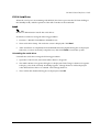
Installing J2RE . . . . . . . . . . . . . . . . . . . . . . . . . . . . . . . . . . . . . . . . . . . . . . . . . . . . . . . . . . . . . . . . . . . . . . 7-9
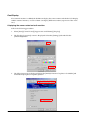
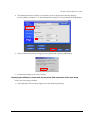
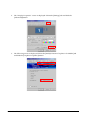
Installing the GUI Utility . . . . . . . . . . . . . . . . . . . . . . . . . . . . . . . . . . . . . . . . . . . . . . . . . . . . . . . . . . . . . . . 7-11
E-mail Setting . . . . . . . . . . . . . . . . . . . . . . . . . . . . . . . . . . . . . . . . . . . . . . . . . . . . . . . . . . . . . . . . . . . . . . 7-13
Buzzer/Sound Setting . . . . . . . . . . . . . . . . . . . . . . . . . . . . . . . . . . . . . . . . . . . . . . . . . . . . . . . . . . . . . . . . 7-16
Display of Popup Message . . . . . . . . . . . . . . . . . . . . . . . . . . . . . . . . . . . . . . . . . . . . . . . . . . . . . . . . . . . 7-17
Using the RAID system . . . . . . . . . . . . . . . . . . . . . . . . . . . . . . . . . . . . . . . . . . . . . . . . . . . . . . . . . . . . . . . . . . . 7-21
OS Startup Operations . . . . . . . . . . . . . . . . . . . . . . . . . . . . . . . . . . . . . . . . . . . . . . . . . . . . . . . . . . . . . . . 7-21
OS Termination Operations . . . . . . . . . . . . . . . . . . . . . . . . . . . . . . . . . . . . . . . . . . . . . . . . . . . . . . . . . . . 7-21
Checking of RAID operations . . . . . . . . . . . . . . . . . . . . . . . . . . . . . . . . . . . . . . . . . . . . . . . . . . . . . . . . . 7-21
Failures and Determining the Failed HDD . . . . . . . . . . . . . . . . . . . . . . . . . . . . . . . . . . . . . . . . . . . . . . . . . . . 7-22
Errors that can be Detected During the System’s Start-up Process . . . . . . . . . . . . . . . . . . . . . . . . . . 7-22
Errors that can be Detected During Operation . . . . . . . . . . . . . . . . . . . . . . . . . . . . . . . . . . . . . . . . . . 7-23
Determining the Failed Hard Disk Drive . . . . . . . . . . . . . . . . . . . . . . . . . . . . . . . . . . . . . . . . . . . . . . . . . 7-24
Building RAID . . . . . . . . . . . . . . . . . . . . . . . . . . . . . . . . . . . . . . . . . . . . . . . . . . . . . . . . . . . . . . . . . . . . . . . . . . 7-26
Establishing RAID system by adding one more hard disk to the normal one-drive system . . . . . . . 7-26
Newly Building RAID System . . . . . . . . . . . . . . . . . . . . . . . . . . . . . . . . . . . . . . . . . . . . . . . . . . . . . . . . . . 7-29
Rebuilding RAID after Replacing One of the Two Hard Disks . . . . . . . . . . . . . . . . . . . . . . . . . . . . . . . 7-31
Canceling the RAID System . . . . . . . . . . . . . . . . . . . . . . . . . . . . . . . . . . . . . . . . . . . . . . . . . . . . . . . . . . 7-32
RAID BIOS . . . . . . . . . . . . . . . . . . . . . . . . . . . . . . . . . . . . . . . . . . . . . . . . . . . . . . . . . . . . . . . . . . . . . . . . . . . . . 7-33
How to Start and Exit the RAID BIOS . . . . . . . . . . . . . . . . . . . . . . . . . . . . . . . . . . . . . . . . . . . . . . . . . . . . 7-33
RAID BIOS Screen Configuration . . . . . . . . . . . . . . . . . . . . . . . . . . . . . . . . . . . . . . . . . . . . . . . . . . . . . . 7-33
Menu Items . . . . . . . . . . . . . . . . . . . . . . . . . . . . . . . . . . . . . . . . . . . . . . . . . . . . . . . . . . . . . . . . . . . . . . . . 7-34
Formatting the Hard Disk Drives . . . . . . . . . . . . . . . . . . . . . . . . . . . . . . . . . . . . . . . . . . . . . . . . . . . . . . . 7-35
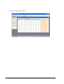
GUI Utility . . . . . . . . . . . . . . . . . . . . . . . . . . . . . . . . . . . . . . . . . . . . . . . . . . . . . . . . . . . . . . . . . . . . . . . . . . . . . . 7-37
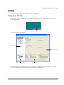
Staring up the GUI Utility . . . . . . . . . . . . . . . . . . . . . . . . . . . . . . . . . . . . . . . . . . . . . . . . . . . . . . . . . . . . . 7-37
How to Operate the GUI Utility . . . . . . . . . . . . . . . . . . . . . . . . . . . . . . . . . . . . . . . . . . . . . . . . . . . . . . . . 7-38
xiv
Rev. D
IR-700 Technical Reference Guide
RAID Event Watch Tool . . . . . . . . . . . . . . . . . . . . . . . . . . . . . . . . . . . . . . . . . . . . . . . . . . . . . . . . . . . . . . . . . .7-60
Startup . . . . . . . . . . . . . . . . . . . . . . . . . . . . . . . . . . . . . . . . . . . . . . . . . . . . . . . . . . . . . . . . . . . . . . . . . . . .7-61
Setting . . . . . . . . . . . . . . . . . . . . . . . . . . . . . . . . . . . . . . . . . . . . . . . . . . . . . . . . . . . . . . . . . . . . . . . . . . . .7-61
Appendix-A Hardware Specifications
System Diagram . . . . . . . . . . . . . . . . . . . . . . . . . . . . . . . . . . . . . . . . . . . . . . . . . . . . . . . . . . . . . . . . . . . . . . . .A-1
System Memory . . . . . . . . . . . . . . . . . . . . . . . . . . . . . . . . . . . . . . . . . . . . . . . . . . . . . . . . . . . . . . . . . . . . . . . .A-2
System Interrupts . . . . . . . . . . . . . . . . . . . . . . . . . . . . . . . . . . . . . . . . . . . . . . . . . . . . . . . . . . . . . . . . . . . . . . .A-3
Hardware Specifications . . . . . . . . . . . . . . . . . . . . . . . . . . . . . . . . . . . . . . . . . . . . . . . . . . . . . . . . . . . . . . . . .A-3
CPU . . . . . . . . . . . . . . . . . . . . . . . . . . . . . . . . . . . . . . . . . . . . . . . . . . . . . . . . . . . . . . . . . . . . . . . . . . . . . . .A-3
Memory (184pin DDR DIMM) . . . . . . . . . . . . . . . . . . . . . . . . . . . . . . . . . . . . . . . . . . . . . . . . . . . . . . . . . .A-3
Real-time Clock . . . . . . . . . . . . . . . . . . . . . . . . . . . . . . . . . . . . . . . . . . . . . . . . . . . . . . . . . . . . . . . . . . . .A-4
Video Controller . . . . . . . . . . . . . . . . . . . . . . . . . . . . . . . . . . . . . . . . . . . . . . . . . . . . . . . . . . . . . . . . . . . .A-4
POS Controller . . . . . . . . . . . . . . . . . . . . . . . . . . . . . . . . . . . . . . . . . . . . . . . . . . . . . . . . . . . . . . . . . . . . . .A-4
HDD . . . . . . . . . . . . . . . . . . . . . . . . . . . . . . . . . . . . . . . . . . . . . . . . . . . . . . . . . . . . . . . . . . . . . . . . . . . . . .A-4
Audio . . . . . . . . . . . . . . . . . . . . . . . . . . . . . . . . . . . . . . . . . . . . . . . . . . . . . . . . . . . . . . . . . . . . . . . . . . . . .A-5
CF Slot . . . . . . . . . . . . . . . . . . . . . . . . . . . . . . . . . . . . . . . . . . . . . . . . . . . . . . . . . . . . . . . . . . . . . . . . . . . .A-5
Serial Device . . . . . . . . . . . . . . . . . . . . . . . . . . . . . . . . . . . . . . . . . . . . . . . . . . . . . . . . . . . . . . . . . . . . . . .A-5
PCI Slots . . . . . . . . . . . . . . . . . . . . . . . . . . . . . . . . . . . . . . . . . . . . . . . . . . . . . . . . . . . . . . . . . . . . . . . . . . .A-5
Printer . . . . . . . . . . . . . . . . . . . . . . . . . . . . . . . . . . . . . . . . . . . . . . . . . . . . . . . . . . . . . . . . . . . . . . . . . . . . .A-6
Drawer . . . . . . . . . . . . . . . . . . . . . . . . . . . . . . . . . . . . . . . . . . . . . . . . . . . . . . . . . . . . . . . . . . . . . . . . . . . .A-6
Ethernet Controller . . . . . . . . . . . . . . . . . . . . . . . . . . . . . . . . . . . . . . . . . . . . . . . . . . . . . . . . . . . . . . . . . .A-6
Dual Display . . . . . . . . . . . . . . . . . . . . . . . . . . . . . . . . . . . . . . . . . . . . . . . . . . . . . . . . . . . . . . . . . . . . . . . .A-7
Electrical Specifications . . . . . . . . . . . . . . . . . . . . . . . . . . . . . . . . . . . . . . . . . . . . . . . . . . . . . . . . . . . . . . . . .A-7
Input Specification . . . . . . . . . . . . . . . . . . . . . . . . . . . . . . . . . . . . . . . . . . . . . . . . . . . . . . . . . . . . . . . . . .A-7
Protection Circuit/Unit . . . . . . . . . . . . . . . . . . . . . . . . . . . . . . . . . . . . . . . . . . . . . . . . . . . . . . . . . . . . . . .A-7
Electrical Capacity to External Devices . . . . . . . . . . . . . . . . . . . . . . . . . . . . . . . . . . . . . . . . . . . . . . . . .A-8
Lithium Battery . . . . . . . . . . . . . . . . . . . . . . . . . . . . . . . . . . . . . . . . . . . . . . . . . . . . . . . . . . . . . . . . . . . . . . . . .A-8
Interface . . . . . . . . . . . . . . . . . . . . . . . . . . . . . . . . . . . . . . . . . . . . . . . . . . . . . . . . . . . . . . . . . . . . . . . . . . . . . .A-9
Serial Connectors . . . . . . . . . . . . . . . . . . . . . . . . . . . . . . . . . . . . . . . . . . . . . . . . . . . . . . . . . . . . . . . . . . .A-9
Parallel Connector (LPT Connector) . . . . . . . . . . . . . . . . . . . . . . . . . . . . . . . . . . . . . . . . . . . . . . . . . . .A-10
DKD Connector . . . . . . . . . . . . . . . . . . . . . . . . . . . . . . . . . . . . . . . . . . . . . . . . . . . . . . . . . . . . . . . . . . . . .A-11
Customer Display Connector . . . . . . . . . . . . . . . . . . . . . . . . . . . . . . . . . . . . . . . . . . . . . . . . . . . . . . . . .A-11
Appendix-B Operating the Product Continuously (24-hours/day)
HDD Motor Stop Setting . . . . . . . . . . . . . . . . . . . . . . . . . . . . . . . . . . . . . . . . . . . . . . . . . . . . . . . . . . . . . . . . .B-1
HDD Power Down Timer Setting . . . . . . . . . . . . . . . . . . . . . . . . . . . . . . . . . . . . . . . . . . . . . . . . . . . . . . .B-1
Windows Update Setting . . . . . . . . . . . . . . . . . . . . . . . . . . . . . . . . . . . . . . . . . . . . . . . . . . . . . . . . . . . . .B-3
Rev. D
xv
xvi
Rev. D
IR-700 Technical Reference Guide
Chapter 1
IR-700 System Overview
IR-700
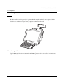
IR-700 is an all in one PC-based POS, equipped with a touch panel LCD and a printer. With a
reduction of 40% in its footprint (compared to the IR-320), and an excellent design that will
blend into the ambience of your store, it supports counter-based work.
Model configurations
The IR-700 is available in various models, offering different combinations of LCD unit, printer
paper width, OS, and color. For detailed information, please refer to our catalog, or contact one
of our sales offices.
Rev. D
IR-700 System Overview 1-1
IR-700 Features
❏ Compact design
•
The footprint is 250 mm in width and 340 mm in depth for the vertical type (rear cover
included). The horizontal type is 250mm in width and 261mm in depth. It can be placed
even where there is limited counter space.
•
The simple round design allows the cables to be stored compactly. It can successfully be
installed even in counter setups where the back of the POS is exposed, such as face-toface counters, as it will blend into the ambience of the store.
❏ Easy to use, reliable hardware
•
The thermal printer uses Epson’s highly-regarded technology, bringing with it an
advanced level of reliability. With a printer cover that is easy to open using either hand,
the roll of paper can be quickly replaced.
•
The product line includes LCD displays of 12.1" SVGA and 15.0" XGA, using a high
luminance level TFT screen. A touch panel that minimizes fingerprints is incorporated.
Its angle can be adjusted so that it is easy to read, even in a bright room.
•
Three kinds of customer displays are available for various purposes. By changing the
positioning and angle, adjustments can be made so that the customers and the operators
can easily view the display.
•
A Magnetic Stripe Reader (MSR) and extended keyboard can be attached to the side of
the LCD display.
❏ Stable operation and downtime reduction
•
RAID1 (mirroring) is supported in models with 2 hard drives installed. Even if one HDD
fails, the other HDD will continue to operate.
•
Maintenance has been improved, including easier replacement of the hard drive and the
main board. This contributes to reduced downtime.
•
The unit can be started up using the CD/DVD-ROM drive or a floppy disc drive
connected to the USB port.
•
The manager key is used for the optional 60-key POS keyboard (DM-KX060), and up to 7
access levels can be set up, depending on the type of key. Access levels to the system can
be set up by the owner or manager, etc.
❏ High-performance
•
The CPU offers power and speed, which is needed for complex programming and data
processing, using a Pentium M/Celeron M and a maximum of 1 GB of memory, as well
as a high-capacity HDD (80GB or more).
•
The use of an HDD connected by 3.5" serial ATA helps to improve reliability.
1-2 IR-700 System Overview
Rev. D
IR-700 Technical Reference Guide
•
Windows 2000 Professional SP4, Windows XP Professional SP2 or Windows Embedded
for Point of Service (WEPOS) is used as the OS. Based on OLE-POS, it can be flexibly
applied to a variety of system configurations.
•
Equipped with 4 serial ports, a parallel port, 2 PCI slots, and 4 USB ports, extensibility is
assured. Serial ports output +5V or +12V.
❏ Compatibility with Epson's IR-320 series is assured. When used as a replacement, support
on the application side can be minimized.
Rev. D
•
Windows 2000 Professional SP4 or Windows XP Professional SP2 is used as the OS. The
IR-320's Windows 2000 Professional model makes replacement easy.
•
OPOS ADK is used. If programs are developed through OPOS ADK, you do not have to
make major changes in the whole application, but only the SO part, even if a peripheral
device has been changed.
•
The printer is compatible with the IR-320. Paper width is 80mm. Can be used without
major changes on the application side (when using OPOS and APD)
•
DM-D110/210/500, which are also used in the IR-320, can be used for the customer
display. In addition, the DM-D120 is compatible with the DM-D110. Can be used
without major changes on the application side (when using OPOS and APD)
•
For the definition data of the 28-key POS keyboard and MSR, the IR-310/320 definition
data can be used.
IR-700 System Overview 1-3
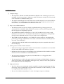
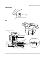
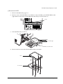
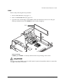
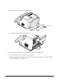
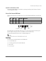
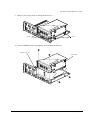
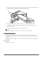
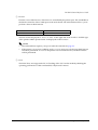
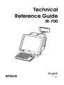
Hardware
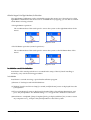
Hardware configurations
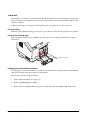
IR-700's hardware can be attached to the options as follows - the configuration makes it easy to
replace HDDs and Main boards.
Rear side
HDD
Main board set
Front side
MSR unit
28KeyPOSKeyboard
1-4 IR-700 System Overview
Rev. D
IR-700 Technical Reference Guide
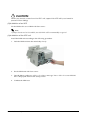
Difference between PC/AT PC and the IR-700
Compared to PC/AT PCs, the following points are different.
❏ Built-in thermal printer, customer display, and cash drawer can be attached.
❏ LCD unit equipped with a touch panel is integrated.
❏ 28 key POS keyboard unit and MSR unit can be mounted on the LCD unit.
❏ Equipped with 4 serial ports, a parallel port, 2 PCI slots, 4 USB ports, extensibility is assured.
Serial ports output +5V or +12V.
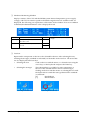
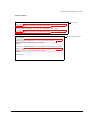
Interface
Interfaces of the IR-700 are as follows:
Rev. D
IR-700 System Overview 1-5
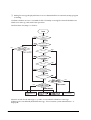
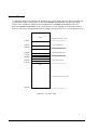
Software configuration
The configuration of the IR-700's software is as follows:
BIOS
The BIOS uses the AMI BIOS as a Core BIOS and supports the Plug & Play BIOS, APM BIOS,
ACPI BIOS 2.0 etc. Setting up the BIOS's settings and changes to the CMOS can be performed
using a utility. The default settings can be saved on a floppy disc and loaded on another IR-700.
The diagnostic functions (Power On Self Test) inspect the system environment and the hardware
when the power is on.
Device diagnostic utility (DIAG)
The device diagnostic utility can inspect the communication line between devices connecting to
IR-700 and check the setting of main board.
The devices that can be tested are as follows:
•
CPU, main board, memory
•
HDD
•
LCD display
•
Printer, customer display
1-6 IR-700 System Overview
Rev. D
IR-700 Technical Reference Guide
The devices that cannot be tested are as follows:
•
LCD touch panel
•
28-key POS keyboard and MSR unit
•
PCI card
•
USB Access Device (60-key POS keyboard included)
Operating system
IR-700 works on the following operating systems.
•
Windows 2000 Professional SP4 or later
•
Windows XP Professional SP2 or later
•
Windows Embedded for Point of Service (WEPOS)
Epson offers HDDs with an OS installed. In addition, a dedicated IR-700 and the utility driver
installation CD-ROM are available as well. Therefore, an OS that the customers bring in can be
used.
Note:
❏ Be sure to back up your data. When you request the repair of an HDD, please be sure to
bring the OS disk.
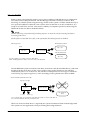
RAID BIOS/Config utility
Models with 2 HDDs can build RAID1 (mirroring). The RAID BIOS checks the RAID status
during startup, and controls the RAID during operation. Even if one HDD fails during startup
or operation, another HDD can continue to operate the system.
In addition, basic matters such as starting and stopping RAID are executed.
GUI utility (RAID Utility for Windows)
The GUI utility monitors the RAID status during Windows operation. When RAID events occur,
it can notify users by email or buzzer. RAID status can also be confirmed.
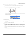
RAID Event Watch tool
The RAID Event Watch tool monitors events of the GUI utility. When RAID events occur, it can
display popup messages in front of an application and create event logs for Windows.
POS controller
Control touch panel/28-key POS keyboard/MSR. Stored in LCD POS board within the LCD
unit. Those are input at USB port 5.
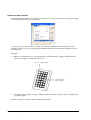
A tool to set the 28-key POS Keyboard definition data and MSR is provided.
Rev. D
IR-700 System Overview 1-7
OLE-POS
The PC/AT architecture allows the use of tools such as Visual BASIC and Visual C++ when
developing the IR-700 applications. As the OLE-POS drivers are provided for POS peripheral
devices, optimal applications for wide use are easily developed. For the latest OLE-POS, please
contact our sales offices. OPOS drivers vary from the printer driver for general Windows. It is
assumed that the programming is executed in a development environment, such as Visual
BASIC. This driver is not supposed to print through applications on the market.
Printer driver-APD
Adding control of printer, customer display, cash drawer to the printer driver for general
Windows enables the driver to control especially for POS purposes.
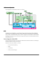
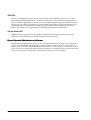
Epson Remote Maintenance Software
With the Remote Maintenance Software, you can manage clients by issuing various jobs from a
server to clients (IR-700) and obtain the execution results via the internet or LAN system. It
enables you to rewrite or obtain definition data of clients in many shops or on many floors all at
once. You can also rewrite the printer firmware. Therefore, a maintenance person does not need
to go to every client to rewrite data, which makes maintenance more effective.
1-8 IR-700 System Overview
Rev. D
IR-700 Technical Reference Guide
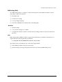
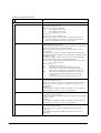
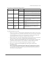
Options
IR-700 offers the following options.
Peripheral devices for the IR-700 include the following.
Hardware
POS Keyboard
Unit
Model number
28-KeyPOS Keyboard
DM-KX028
60-KeyPOS Keyboard
DM-KX060
MSR Unit
DM-MX123
Customer display
DM-D120 (Pole unit DP-506 included)
DM-D110
DM-D210
DM-D500
Customer display pole unit
DP-506
Powered USB Board
OI-X06
Printer
Printer unit
TM-T88IIIX
Printer tray
OI-X01
Dummy cover
OI-X02
Operation Testing Products for IR
The Operation Confirmed items are marketed by Epson and are built-in, included, or connected
to an Epson POS product, and operation by has been confirmed by Epson. Epson can also offer
reference information for the selection of peripheral devices to the customer who constructs a
system using Epson POS products. Please inquire what kind of device can be used from Epson
or the selling agent.
This operation confirmation evaluates the equipment in test environments and conditions, but it
does not guarantee the operation. Therefore, procurement and evaluation by the customer are
required.
Rev. D
IR-700 System Overview 1-9
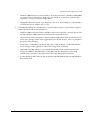
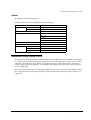
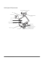
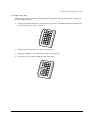
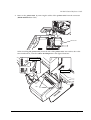
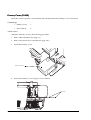
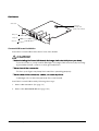
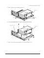
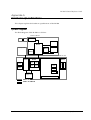
Part Names
The part names are as follows:
Printer control panel
Customer display
Power switch
Printer cover
Printer unit
Customer
display
(Option)
Pole
LCD lock lever
rear cover
LCD unit
Power LED
MSR unit
(option)
28-Key POS Keyboard
(option)
HDD LED
Side cover
Front cover
USB
LCD intensity control button
60-Key POS Keyboard (option)
Power switch
Key lock key
Front cover open
Power switch
Disabling switch
ON
OFF
Power switch
PRINTER RESET
RESET
TM Printer switch
1-10 IR-700 System Overview
Reset switch
Rev. D
IR-700 Technical Reference Guide
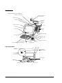
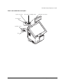
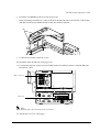
Side cover open
USB
Speaker volume
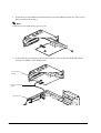
Rear
TM printer power connector
Rear Cover
Printer unit
Powerd USB
HDD
24V Jack
24V port
AC inlet
Drawer
COM6
COM5
Parallel
Mouse
PCI slot
Keyboard
Ethernet
12V port
COM1
COM2 Display DM-D
USB
5V port
Line out
Microphone
Rev. D
IR-700 System Overview 1-11
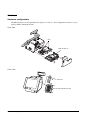
Vertical type (OI-X03) part names
Customer display power switch
Pole
Front cover
Customer display
(option)
Side cover
LCD unit
LCD lock lever
Back cover
Printer unit
Printer cover
Paper feed switch
Stand cover
Power LED
1-12 IR-700 System Overview
HDD LED
No paper LED
LCD intensity control button
Rev. D
IR-700 Technical Reference Guide
Front cover and side cover open
System rest switch
Power switch disabling switch
TM Printer reset switch
Power switch
Speaker volume
USB
Rev. D
IR-700 System Overview 1-13
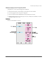
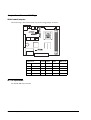
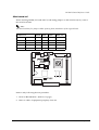
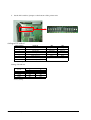
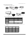
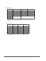
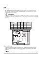
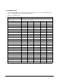
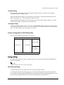
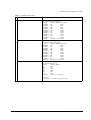
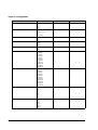
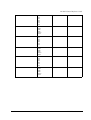
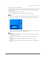
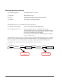
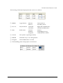
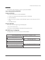
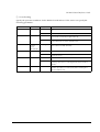
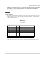
Jumper Locations and Settings
Main board jumpers
The following is the main board's layout showing jumper locations.
Jumper block
Default
+5V
output
+12V
output
CMOS clear
JP 2801
COM1
1-2
3-4
5-6
---
JP 2802
COM2
1-2
3-4
5-6
---
JP 2901
COM6
1-2
3-4
5-6
---
JP 2902
COM5
1-2
3-4
5-6
---
JP 1601
CMOS clear
1-2
---
---
2-3
IR-700 operation
See the IR-700 users manual.
1-14 IR-700 System Overview
Rev. D
IR-700 Technical Reference Guide
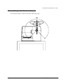
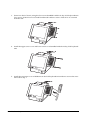
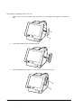
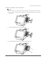
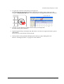
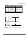
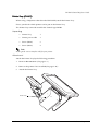
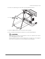
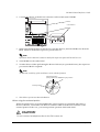
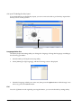
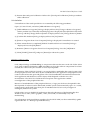
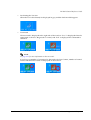
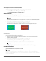
Movable Range of the Customer Display
The customer display can be moved in the following range.
Rev. D
IR-700 System Overview 1-15
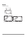
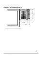
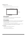
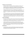
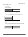
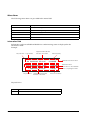
Dimensions
Dimensions
Connected 15" LCD unit
54
250
54
388
439
286
254
254
250
340
340
The size shown above is for reference and is not guaranteed.
1-16 IR-700 System Overview
Rev. D
IR-700 Technical Reference Guide
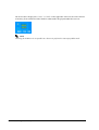
Connected 12.1" LCD unit
32
250
32
369
432
285
254
254
233
340
340
The size shown above is for reference and is not guaranteed.
Rev. D
IR-700 System Overview 1-17
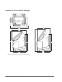
Connected 15" LCD unit (Vertical Stand type)
358
237
278
482
426
362
362
261
261
The size shown above is for reference and is not guaranteed.
1-18 IR-700 System Overview
Rev. D
IR-700 Technical Reference Guide
Connected 12.1" LCD unit (Vertical Stand type)
237
314
277
453
405
362
362
261
261
The size shown above is for reference and is not guaranteed.
Rev. D
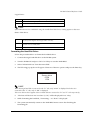
IR-700 System Overview 1-19
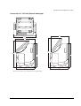
Connected 28-key POS keyboard and MSR Unit
156
174
115
152
The size shown above is for reference and is not guaranteed.
1-20 IR-700 System Overview
Rev. D
IR-700 Technical Reference Guide
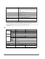
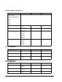
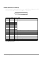
Specifications
IR-700
Item
CPU
Memory
Specification
CPU
Intel® Pentium®M or Intel Celeron®M
Socket
mPGA479M socket
Secondary cache
memory
Built in the CPU.
Intel Pentium M 2 MB
Intel Celeron M 512 KB
Main memory
184 pin DDR SDRAM DIMM slot × 2, Max. 1 GB
(Supports up to DDR DIMM PC2700.)
BIOS ROM
8 MBit
Chip set
Intel 855GME/ICH4 chip set
Video controller
Sub storage
Sub storage
Interface
Built-in chip set (Supports dual display.)
Chip set
1024 × 768; 256K colors (16770 K)
Video controller
800 × 600; 256K colors (16770 K)
HDD
Serial ATA interface with 1 or 2 built in-type 3.5” HDD.
(RAID-ready)
CF interface
On-board 1 slot
Ethernet
10 BASE-T / 100 BASE-TX is included as standard.
Wake On LAN available
(*1)
Keyboard/mouse
× 1 PS/2-compliant (6-pin mini-DIN)
× 1 PS/2 mouse-compliant (6-pin mini DIN)
Serial
× 4 (D-sub male 9-pin)
Setting jumper allows output + 5 V or +12 V to pin 1.
Supports Wake up function (Modem Ring On) of pin 9 (RI)
(*2)
Parallel
Expansion slot
× 1 (D-sub female 25-pin) Supports EPP/ECP
CRT
(*3)
× 1 (D-sub female 15-pin)
USB
(*4)
External Hi-speed USB (USB 2.0) × 4 (high/full/low speed
support)
Internal × 3 (For POS controller, printer extension, and Powered
USB board)
Customer display
× 1 (RJ-45)
Drawer (DK)
× 1 (Installed in the TM printer.)
(*5)
Power supply for the
external printer
× 1 (When the TM printer is not installed.)
Audio functions
Sound can be output to the built-in speaker.
External line-out and MIC are provided.
PCI slot
× 2 (3.3 V power supply is provided.) (Revision 2.2)
180 dpi/80 mm width
model
Thermal receipt printer 150 mm/s
Speaker
Printer unit
Rev. D
Built-in monaural speaker (with hardware volume control)
BIOS
Supports ACPI 2.0b/APM 1.2/Plug & Play/DMI
Supported OS
Windows2000 Professional SP4 or later
Windows XP Professional SP2 or later
WindowsEmbedded for Point of Service
POS control firmware
Dedicated keyboard, MSR unit, firmware for touch panel unit
control
IR-700 System Overview 1-21
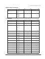
Item
Specification
Lithium battery
The IM-700 is internally equipped with a lithium nonrechargeable battery that supplies the backup voltage to the
RTC and the RTC’s built-in CMOS RAM when AC power is not
supplied.
Battery type: CR2032
Battery life: Approximately 5 years
Power supply
AC 100 V ~ 240 V/50 Hz ~ 60 Hz
Max. 4.0 A
Temperature
Operation: 5 °C ~ 35 °C
Storage: -10 °C ~ 50 °C
Humidity
Operation: 30%RH ~ 80%RH (No condensation)
Storage: 30%RH ~ 90%RH (No condensation)
Case color
Epson cool white/Epson dark gray
Overall dimensions
250 mm (W) × 340 mm (D) × 254 mm (H)
(Base unit only, rear cover included, LCD and customer display
excluded)
Mass
Approx. 6.4 kg (TM-printer, LCD, and HDD excluded)
*1. Ethernet controller/sound controller are included in the standard package, and are separable in the BIOS setting.
*2. Apart from the 4 external ports, the dedicated TM printer and the customer display use 1 port each. (COM3 for the dedicated
TM printer, and COM4 for customer display by default setting) To use the external COM5 and COM6, an unneeded device must
be disabled by BIOS setting, and interrupt request line (IRQ) must be assigned to COM5 and COM6.
*3. Contents can be displayed separately on the CRT and LCD using the dual display function.
*4. Apart from the 4 external ports, 3 ports are provided for the POS controller, for printer extension (reserve), and for powered USB
board extension.
*5. When the dedicated TM printer is attached, a drawer can be connected to this interface.
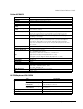
LCD
Item
LCD
Backlight
Touch panel
DM-LX150XG
Size
Type 15"
Type
Color TFT
DM-LX121SV
Type 12"
Resolution
1024 × 768 dots
Display color
256K (Approx. 260K)
800 × 600 dots
Number of
backlights
2 lights
Brightness
280 cd/m2 typ.
Method
Resistive film (Data can be entered using the touch panel.)
Surface solidity
3H or more (JIS K-5600, ISO/DIS 15184)
Positioning
accuracy
± 5 mm maximum
Fingerprint
resistance
Supported
272 cd/m2 typ.
Waterproof
Touch panel surface equivalent to IEC 60529
(JIS C 0920 IPX1)
External interface
1, For DM-MX123 or DM-KX028
LCD
POWER LED, HDD LED
Power supply
DC +3.3, +12 V (Supplied by the IR-700.)
Overall dimensions
355 mm (W) × 280 mm (D)
× 75 mm (H)
314 mm (W) × 254 mm (D) × 89 mm (H)
Mass
Approx. 3.5 kg
Approx. 2.8 kg
1-22 IR-700 System Overview
Rev. D
IR-700 Technical Reference Guide
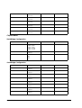
Printer TM-T88IIIX
Item
180 dpi/80 mm width
Print head
Thermal line
Dot density
180 dpi × 180 dpi [Dots per 25.4 mm {1"})
Print control
Unidirectional with friction feed
Print width
72 mm, 512 dots
Characters per line
(Default)
Font A: 42, Font B: 56
Character spacing
(Default)
Font A: 0.28 mm (2 dots)
Font B: 0.28 mm (2 dots)
Character size (W × H)
Standard/double-height/double-width/double-height, double-width
Font A: 1.41 × 3.39 mm/1.41 × 6.77 mm/2.82 × 3.39 mm/2.82 × 6.77 mm
Font B: 0.99 × 2.40 mm/0.99 × 4.80 mm/1.98 × 2.40 mm/1.98 × 4.80 mm
Character sets
Alphanumeric: 95, International: 37, Extended graphic: 128 × 11 page
(Including 1 space page)
Print speed
High-speed mode: Approx. 150 mm/s max. 47.2 lps max. (When paper feed is at
3.18 mm), 35.5 lps max. (4.23 mm, density level 1); print speed is adjusted
automatically, depending on the voltage and print head temperature.
Low power consumption mode: approx. 16.5 lps (When paper feed is at 4.23
mm), 70 mm/s
Ladder bar code: approx. 42 mm/s
Paper feed speed
Approx. 150 mm/s, continuous paper feeding
Line spacing (default)
4.23 mm
Roll paper (single-ply)
Size: width 79.5 mm ± 0.5 mm
Max. outside diameter: 80 mm
Roll paper spool diameter: inside 12 mm, outside 18 mm
Recommended thermal roll Specified: NTP080-80 (Nakagawa Manufacturing Co., Ltd.)
paper
Original: TF50KS-E (Nippon Paper Industries Co., Ltd.)
Packaged roll paper: Original: PD150R (Oji Paper Mfg. Co.,Ltd.)
Interface
Dedicated for the IR-700 (serial)
Receive buffer
4 KB/45 byte
D.K.D function
2 drives
Power supply
DC +24 V ± 7%, supplied by the IR-700
Life
Mechanism: 15,000,000 lines
Thermal head: 100 million pulse, 100 km
Autocutter: 1,500,000 cuts
Overall dimension
143.6 mm (W) × 132.8 mm (D) × 197 mm (H)
Mass
Approx. 1.5 kg
lps: lines per second, dpi: dots per 25.4 mm {1"} (dots per inch)
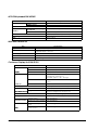
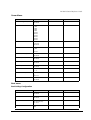
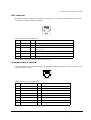
28 POS Keyboard DM-KX028
Item
Key switch
Connection
Power supply
Specification
Alignment
7×4
Number of keys
28
Connector for connecting to
the main unit
Can be connected to the side of the LCD unit with the
dedicated 40 pin connector.
Connector for connecting an
external device
DM-MX123 can be connected with the dedicated 40pin connector.
DM-LX series supplies DC +3.3 V
Overall dimensions
137 mm (W) × 174 mm (D) × 58 mm (H)
Mass
Approx. 500 g
Rev. D
IR-700 System Overview 1-23
60 POS Keyboard DM-KX060
Item
Key switch
Specification
Alignment
6 × 10
Number of keys
60
Keylock
8 positions
Interface
Connector for connecting to
the main unit
USB 1.1 compliant Type A connector
USB downstream
× 2 USB 1.1 compliant
Overall dimensions
250 mm (W) × 140 mm (D) × 52 mm (H)
Cable length
550 mm
Mass
Approx. 800 g
MSR Unit DM-MX123
Item
Specification
Supported card
ISO 7811/JIS X6301 Type 1, track 1, 2, 3
Connection
Can be connected to the side of the LCD unit or to the DM-KX028 with the
dedicated 40-pin connector.
Power supply
DC 3.3 V
Overall dimensions
54 mm (W) × 156 mm (D) × 53 mm (H)
Mass
Approx. 200 g
Customer Display Unit DM-D120
Item
Display
Character
Specification
Character
40 characters (20 columns × 2 lines)
Color
Green (505 mm)
Luminance
690 cd/m2
Character type
Alphanumeric characters: 95
International characters: 37
Extended graphics: 128 × 12 pages
Character structure
5 × 7 dot matrix
Cursor
Character size
3.5 mm × 5.0 mm
Power supply
DC 12V (provided from the IR-700)
178 mm (W) × 60 mm (D)
Height
Overall dimensions
When the crank poll is used: 130 mm
When the straight poll is used: 167 mm
Poll
Crank poll (DP-506), Straight poll
Tilt angle
48° at maximum (4 levels, 5 positions)
Display section
Horizontal rotation
Mass
300° at maximum
Crank poll section (DP-506) 270° at maximum
When the crank poll is
used
Approx. 357 g
When the straight poll is
used: 167 mm
Approx. 324 g
1-24 IR-700 System Overview
Rev. D
IR-700 Technical Reference Guide
Chapter 2
OS and Drivers
Outline of This Chapter
This chapter tells which Operating Systems and Drivers can be used and how to install and
uninstall them.
CAUTION:
Don’t write anything, such as an application to an HDD that is removed from the IR-700.
The vibration and impact can cause trouble and the failure of the HDD.
Operating Systems
The following Operating Systems can be used for the IR-700.
❏ Windows 2000 Professional SP4
(There is a version preinstalled by EPSON)
❏ Windows XP Professional Edition SP2
(There is a version preinstalled by EPSON)
❏ Windows Embedded for Point of Service (WEPOS)
(There is a version preinstalled by EPSON)
Drivers and Utilities
Drivers for using the IR-700 are on the Driver CD-ROM included with the IR-700. If the
operating system is pre-installed on the HDD, the printer driver, the customer display driver,
and the ERM are not installed.
Rev. D
OS and Drivers 2-1
Driver CD-ROM for the IR-700
In case you use a locally procured OS on the IR-700, the drivers for using the peripheral devices
are on this CD-ROM.
The CD-ROM directory is shown below.
Root
|--- COMMON
| |--- 60KEYCFG
| |--- APDRV
| |--- ERM
| |--- OPOSADK
| |--- POSDVCFG
|--- DOS62
| |--- NETWORK
|--- WIN2K
| |--- 60KEYCFG
| |--- CHIPSET
| |--- EPSERIAL
| |--- LOGON
| |--- NETWORK
| |--- POSDEV
| |--- SATARAID
| | |--- DRIVER
| | |--- TOOL
| |--- SOUND
| | |--- config
| | |--- patch
| | | |--- win98
| | |--- wdm
| |--- TOUCH
| |--- VIVEO
|--- WINXP
|--- 60KEY
|--- CHIPSET
|--- EPSERIAL
|--- NETWORK
|--- POSDEV
|--- SATARAID
| |--- DRIVER
| |--- TOOL
|--- SOUND
| |--- config
| |--- patch
| | |--- win98
| |--- wdm
|--- TOUCH
|--- VIDEO
2-2 OS and Drivers
:
:
:
:
:
:
:
:
:
:
:
:
:
:
:
:
:
:
:
:
:
:
:
:
:
:
:
:
:
:
:
:
:
:
:
:
:
CDVER.TAG
Common OS utility drivers
60-key POS keyboard definition utility
Advanced Printer driver
Epson Remote Maintenance Software
OPOS ADK(Printer, Customer Display and Drawer)
MSR setting utility/ 28-key Definition Utility
Drivers for MS-DOS
Network drivers
Drivers for Windows2000
60-keyPOSkeyboard driver
Chipset drivers
Serial Driver
Logon tool
Network drivers
POS device controller Driver
SATA RAID related driver folder
SATA-RAID Driver
GUI Utility, RAID Event Monitoring Tool
Sound drivers
Touch Panel drivers
Video drivers
Drivers for Windows XP
60-key POS Keyboard drivers
Chipset drivers
Serial tool
Network drivers
POS device controller Driver
SATA RAID related driver folder
SATA-RAID Driver
GUI Utility, RAID Event Monitoring Tool
Sound drivers
Touch Panel drivers
Video drivers
Rev. D
IR-700 Technical Reference Guide
Readme.txt files are in both the root directory and in subdirectories of the root directory.
1. The Readme.txt file in the root directory contains an overview of this CD-ROM and
refers to the Readme.txt files in the various subdirectories.
2. The Readme.txt files in the operating system subdirectories explain driver installation/
un-installation for each operating system.
3. Readme.txt files for KEYCFG, OPOS-ADK, and APDRV are included with the software.
Rev. D
OS and Drivers 2-3
Windows 2000 Pre-Installed Model
The exclusive EPSON utility and drivers for using IR-700 are pre-installed in the HDD with the
pre-installed Windows 2000 Professional.
Installation Procedure
Windows 2000 Installation
When the power supply is turned on, the installation starts. Enter the product
key of the W2K label pasted on the product. You can set up the Network
automatically or set it up later.
Change of Double click settings
Set up this setting every time a new user starts using Windows 2000.
Setting of RAID
If there are 2 installed HDDs and you are going to use a RAID system, set it
up.
Other software Installation
Install utilities such as serial driver, 28-key, MSR, and 60-key from backup
folder if necessary.
2-4 OS and Drivers
Rev. D
IR-700 Technical Reference Guide
Formatting the hard disk
The hard disk is composed of one partition of up to 10 GB as a system area. For a hard disk of
more than 10 GB, the excess area other than the system area is not yet formatted. This drive can
be converted to NTFS using the Convert command. Use the disk administrator when creating a
drive in the unused area. The start-up drive has been formatted to the following file system.
•
File system: FAT32
•
Volume label: Windows 2000
Pre-installed software
❏ Microsoft Windows 2000 Professional
❏ Microsoft Windows 2000 Service Pack 4
❏ Microsoft Windows 2000 Multilingual User Interface Pack
❏ Intel Chipset software installation utility
❏ Intel Video driver
❏ Intel Network driver
❏ Realtek Sound driver
❏ Silicon Image SATA-RAID driver
❏ EPSON Touch Panel driver
❏ EPSON Logon tool *1
❏ EPSON Pos Device Utilities *1
❏ EPSON 60-key POS keyboard definition utility *1
❏ EPSON Serial driver *1
Note:
*1: These are not installed during the auto installation procedure.
Rev. D
OS and Drivers 2-5
Version of the Pre-installation HDD
To confirm the version of the HDD, see the file HDVER.TAG in the root directory of the boot
drive. This file is text-formatted and can be read using Notepad or a similar text editor. The file
HDVER.TAG has the following contents:
[HD Information]
MODEL=IM-700
OS=Windows2000
LANG=Dutch/English/French/German/Italian/Portuguese/Russian/Spanish
VER=1.**.*
Directory Configuration
The root directory of the HDD is structured as follows.
|--- Backup
|
|--- 60KEYCFG
|
|
|--- DRIVER
|
|
|--- TOOL
|
|--- CHIPSET
|
|--- EPSERIAL
|
|--- LOGON
|
|--- NETWORK
|
|--- POSDVCFG
:
:
:
:
:
:
:
:
|
|
|--- DRIVER
|
|
|--- TOOL
|
|--- SATARAID
|
|
|--- DRIVER
|
|
|--- TOOL
|
|--- Sound
|
|
|--- config
|
|
|--- patch
|
|
|--- wdm
|
|--- TOUCH
|
|--- VIDEO
|--- I386
|--- Mui
|--- Program Files
|--- WINNT
:
:
:
:
:
:
:
:
:
:
:
:
:
:
:
60-key POS keyboard definition utility
60-key POS keyboard driver
Utility
Chipset driver backup folder
EPSON Serial driver backup folder
Logon tool backup folder
Network driver backup folder
POS device (28-key POS keyboard, MSR) related utility
backup folder
POS device controller drivers
Utility
SATA RAID related driver backup folder
SATA-RAID driver
GUI Utility, RAID Event Monitoring Tool
Sound driver backup folder
Touch Panel driver backup folder
Video driver backup folder
Setup file folder
Microsoft Windows XP Multilingual User Interface Pack
Windows utility folders
Windows folders
The I386 directory may be deleted after the addition of the Windows 2000 application and the
addition / change of the driver.
The directories under the Backup directory are the backups for drivers and utilities. Each of
these directories can be backed up into CD-R or other media. After being backed up, these
directories may be deleted.
If you install the optional CD-R/RW drive, you need to get software for CD-R/RW writing. The
software is not supplied by EPSON.
2-6 OS and Drivers
Rev. D
IR-700 Technical Reference Guide
Windows 2000 Setup Procedure
CAUTION
Be sure to keep the keyboard connected. If necessary, start the setup procedure after
connecting the mouse.
The keyboard is necessary for inputting the product ID and password. The keyboard is
also necessary for user verification during logon to Windows 2000, even if the touch
panel is in a usable state.
Windows 2000 is set up by using the following procedure.
1. Turn on the system, and boot the system from the pre-installation HDD. Windows 2000
setup will start.
2. The License Agreement screen is displayed. Check the contents, then select [I accept this
agreement] and click Next.
3. The Regional Settings screen is displayed. Make sure the system locale, user locales and
keyboard layout are set to United States, then click Next.
4. The Personalize Your Software screen is displayed. Input the Name and Organization, then
click Next.
5. The Your Product Key screen is displayed. Input the product key entered on the cover of the
First Step Guide in the COA (Certificate of Authenticity) package included with this
product; then click Next.
6. The Computer Name and Administrator Password screen is displayed. Input the Computer
Name and Administrator Password, then click Next.
7. The Date and Time Settings screen is displayed. Set the date and time, then click Next.
8. The Networking Settings screen is displayed. Select either Typical Settings or Custom
Settings according to the environment, then click Next. The Networking Components screen
is displayed if Custom Settings is selected. Set the settings in accordance with the
environment, then click Next.
9. The Workgroup or Computer Domain screen is displayed. Set the settings in accordance
with the environment, then click Next.
10. The system will start automatically when Restart is clicked.
11. The Network Identification Wizard starts. Click Next.
12. The Users of this Computer screen is displayed. Set the settings in accordance with the
environment, then click Next.
13. The Completing the Network Identification Wizard screen is displayed. Click Finish.
14. Windows 2000 starts and the setup is completed.
Rev. D
OS and Drivers 2-7
Setting the recognition range of the double click
When Windows 2000 is installed, the permissible double click level is limited and it is difficult to
double click with your finger. To change the permissible double click level, start up the EPSON
Touch Panel Configuration Tool. It changes the registry key automatically. This setting makes
easy to double click with your finger.
However, when a new user first logs on, the permissible level is limited because the default
value of Windows is the value of the registry key. So the registry key must be modified for
individual users.
When Windows 2000 is set up and a new user is created, the registry key must be modified for
individual users by following the steps below.
Note
The administrator modifies the registry key.
Method
Select Programs - Epson Touch Panel Tool - Touch Panel Configuration Tool from the Start
menu. Click OK. (There is no need to do any other operation.)
Various Configurations (Windows 2000)
To change their configurations, use the control panel.
Setting the Network
A dialog box prompting the user to manually install the network is displayed. Set the network
settings by the following procedure.
1. Open the Control Panel, then select Network and Dial-up Connections.
2. The Network and Dial-up Connections dialog box is displayed. Select Make New
Connection.
3.
The Network Connection Wizard starts. If the location information setting has not been
completed by this time, the Location Information dialog box is displayed at this time. Set the
settings in accordance with the environment, then click OK. If all the location information
has been set, this dialog box is not displayed. Proceed to item (5) and set the settings in
subsequent steps.
4. The Telephone and Modem Option dialog box is displayed. Select the location set in the
previous item, then click OK.
2-8 OS and Drivers
Rev. D
IR-700 Technical Reference Guide
5. The Network Connection Wizard opening dialog box is displayed. Click Next.
6. The Network Connection Type dialog box is displayed. Set the settings in accordance with
the environment; then click Next. The dialog displayed by the following procedure is
different depending on the type of the set network connection. The explanation here is for
the case in which Connect directly to another computer is selected. Setting of other network
connections can be accomplished in the same way by following instructions of the Network
Connection Wizard.
7. The Host or Guest dialog box is displayed. Set the settings in accordance with the
environment, then click Next. The explanation here is for the case in which Host is selected.
8.
The Connection Device dialog box is displayed. Set the settings in accordance with the
environment, then click Next.
9. The Allowed Users dialog box is displayed. Set the settings in accordance with the
environment, then click Next.
10. The Completing the Network Connection Wizard dialog box is displayed. Input the name to
be given to the current settings, then click Finish.
11. The newly set connection is added to the Network and Dial-up Connection dialog box. To
change the connection method, right click on the newly added icon, and select Properties.
The settings can then be changed.
Rev. D
OS and Drivers 2-9
EPSON Serial Driver
When the serial port is transmitting with Windows 2000, this Driver prevents the OS from
shifting to the Standby mode, and the operation of the full-on mode can be continued.
When installing the service pack, install the serial driver again.
Install
Note
Be sure an administrator installs the serial driver.
Install the serial driver using the following procedure.
1. Execute C:\backup\epserial\Epserial.exe.
2. Start serial driver Setup. The welcome screen is displayed. Click Next.
3. After installation is completed, the InstallShield Wizard Complete dialog box is displayed.
Select Yes, I want to restart my computer now, then click Finish to restart the system.
Uninstall
Uninstall the serial driver using the following procedure.
1. Open the Control Panel and select Add/Remove Programs.
2. The Add/Remove Programs dialog box is displayed. Click Change or Remove Programs to
display a list of the currently installed programs. Change/Remove will be displayed when
EPSON Serial Driver is selected. Click Change/Remove.
3. The Confirm File Deletion dialog box is displayed. Click Yes.
4. The Remove Programs From Your Computer dialog box is displayed. The uninstall process
then begins.
5. A dialog box is displayed when uninstall is completed. Click OK.
2-10 OS and Drivers
Rev. D
IR-700 Technical Reference Guide
Dual Display
If an external monitor is added, the IR-700 can display the same content on both the LCD display
and the external monitor, or each of them can display different content (expansion of the work
area).
Displaying the same content on both monitors
Follow the following procedure.
1. Select [Start]-[Settings]-[Control Panel]-[Display]
2. The [Display Properties] screen is displayed. Select the [Settings] tab and click the
[Advanced] button.
3. The following screen is displayed. Select the [Intel(R) Extreme Graphics 2 for Mobile] tab
and click the [Graphics Properties] button.
Rev. D
OS and Drivers 2-11
4. The [Intel(R) Extreme Graphics 2 for mobile] screen is displayed. Select the [Display
Devices] button and then check the [Intel(R) Dual Display Clone], and click the [OK] button..
5. The [Confirm the Desktop Change] screen is displayed. Click the [OK] button.
6. Each monitor displays the same content.
2-12 OS and Drivers
Rev. D
IR-700 Technical Reference Guide
Displaying different content on each monitor (expansion of the work area)
Follow the following procedure.
1. Select [Start]-[Settings]-[Control Panel]-[Display]
2. The [Display Properties] screen is displayed. Select the [Settings] tab and click the
[Advanced] button.
3. The following screen is displayed. Select the [Intel(R) Extreme Graphics 2 for Mobile] tab
and click the [Graphics Properties] button.
Rev. D
OS and Drivers 2-13
4. The [Intel(R) Extreme Graphics 2 for Mobile] screen is displayed. Select the [Display
Devices] button and then check the [Extended Desktop] button, and click the [OK] button.
5. Change the method of allocating the work area by dragging and dropping the icons of the
monitors.
2-14 OS and Drivers
Rev. D
IR-700 Technical Reference Guide
6. Click the [Display Settings] button. Change the setting of each monitor, and click the [OK]
button.
7. The [Confirm Desktop Change] screen is displayed. Click the [OK] button.
Adding Windows 2000 Applications
When adding any Windows 2000 application, specify the C:\I386 directory. In this directory,
\I386 has been backed up from the Windows 2000 DVD-ROM.
Rev. D
OS and Drivers 2-15
Support Information
Right click the My Computer icon and select Properties from the pull down menu. Then the
System properties are displayed.
Click the Support information button, so the information on the contact is displayed
2-16 OS and Drivers
Rev. D
IR-700 Technical Reference Guide
Recovering the OS
Preparing confirmation
Confirm the following before OS recovery.
❏ DVD-ROM drive is prepared by the user.
❏ "The Windows 2000 DVD-ROM" included with the product is used for recovering Windows
2000.
❏ In the model with 2 installed HDDs, construct the RAID first, then perform OS recovery to
construct the RAID.
❏ Use the HDD included in the shipment or an unused HDD for OS recovery.
❏ The external keyboard is necessary for the recovery.
❏ In the setup of OS after recovering the OS, it is necessary to enter the product ID. In EPSON
OS pre-installed model, the product ID is printed on the Windows sticker label on the side of
the system.
❏ Set the BIOS setting to "Optimal Defaults." When using the customized BIOS setting, note
down the BIOS setting value beforehand. After the recovery is done, you must reset it to that
value.
❏ OS recovery erases all contents of the HDD. Back up the necessary data to a USB Memory
Stick or other media.
Recovering method
Follow the steps below to carry out OS recovery.
1. Turn power to the IR-700 off. Pull out the power cord from the IR-700.
2. Remove the peripheral devices.
3. Install the HDD unit for which OS recovery will be done to the IR-700 main body. For the
single HDD model, install it on the R side.
CAUTION:
Insert the HDD as far as you can or it may cause a poor connection.
4. Connect the external keyboard to the IR-700 keyboard connector and connect the DVD-ROM
Drive to the USB connector on the side.
5. Connect the power cord to the IR-700.
6. Boot the system, press the Del key during the POST process, and the BIOS setup will start.
7. To set the BIOS to Optimal Defaults, execute Load Optimal Defaults in the Exit menu.
8. Set to the DVD-ROM model number connecting 1st Boot Device of Boot Device Priorityin
the Boot menu.
Rev. D
OS and Drivers 2-17
9. Set the USB 2.0 ControllerMode to Hispeed in the Advanced menu.
10. Select "Save Changes and Exit" in the Exit menu, and press the Enter key. The following
dialog box is displayed.
Save configuration changes and exit setup?
[OK]
[Cancel]
11. Select [OK], and press the Enter key.
12. The system will reboot. Insert the "Windows 2000 DVD-ROM" into the DVD-ROM drive.
13. The following message will appear. Select and enter the partition size of the HDD.
Please select the system partition size.
1: 10GB (Default size)
F: Full size of HD.
Please push a key of 1 or F._
14. Select the range to format as the system area on the hard disk. Press the "1" key to select
10GB or press the "F" key to select the full size. After that, the OS recovery starts.
15. When the prompt below is displayed on the screen, OS recovery work is complete.
c:\RESTORE>_
16. Eject the "Windows 2000 DVD-ROM" from the DVD-ROM drive.
17. Reboot and start the BIOS setup utility.
18. Set USB 2.0 ControllerMode to Full Speed in the Advanced menu.
19. Set to the HDD model number connecting 1st Boot Device of Boot Device Priority in the Boot
menu.
20. Select "Save Changes and Exit" in the Exit menu, and press the Enter key. The following
dialog box is displayed.
Save configuration changes and exit setup?
[OK]
[Cancel]
21. Select [OK], and press the Enter key.
Detach the external keyboard.Limitation
❏ Recovery cannot be performed starting from a hard disk. You must perform recovery from a
DVD-ROM.
2-18 OS and Drivers
Rev. D
IR-700 Technical Reference Guide
Windows XP Pre-Installed Model
The exclusive EPSON utility and drivers for using IR-700 are pre-installed in the HDD with the
pre-installed Windows XP Professional.
Installation Procedure
Windows XP Installation
When the power supply is turned on, the installation starts. Enter the product
key of the WXP label pasted on the product. You can set up the Network
automatically or set it up later.
Change of Double click settings
Set up this setting every time a new user starts using Windows XP.
Setting of RAID
If there are 2 installed HDDs and you are going to use a RAID system, set it
up.
Other software Installation
Install utilities such as serial driver, 28-key, MSR, and 60-key from backup
folder if necessary.
Activation
Authenticate the license by the network or by telephone.
Rev. D
OS and Drivers 2-19
Formatting the hard disk
The hard disk is composed of one partition of up to 10 GB as a system area. For a hard disk of
more than 10 GB, the excess area other than the system area is not yet formatted. This drive can
be converted to NTFS using the Convert command. Use the disk administrator when creating a
drive in the unused area. The start-up drive has been formatted to the following file system.
•
File system: NTFS
•
Volume label: Windows XP
Pre-installed software
❏ Microsoft Windows XP Professional
❏ Microsoft Windows XP Service Pack 2
❏ Microsoft Windows XP Multilingual User Interface Pack
❏ Intel Chipset software installation utility
❏ Intel Video driver
❏ Intel Network driver
❏ Realtek Sound driver
❏ Silicon Image SATA-RAID driver
❏ EPSON Touch Panel driver
❏ EPSON 60-key POS keyboard definition utility*1
❏ EPSON Serial driver *1
Note:
*1: These are not installed during the auto installation procedure.
2-20 OS and Drivers
Rev. D
IR-700 Technical Reference Guide
Version of the Pre-installation HDD
To confirm the version of the HDD, see the file HDVER.TAG in the root directory of the boot
drive. This file is text-formatted and can be read using Notepad or a similar text editor. The file
HDVER.TAG has the following contents:
[HD Information]
MODEL=IM-700
OS=WindowsXP OEM
LANG=Dutch/English/French/German/Italian/Portuguese/Russian/Spanish
VER=1.**.*
Directory Configuration
The root directory of the HDD is structured as follows.
|--- Backup
|
|--- 60KEYCFG
|
|
|--- DRIVER
|
|
|--- TOOL
|
|--- CHIPSET
|
|--- EPSERIAL
|
|--- NETWORK
|
|--- POSDVCFG
:
:
:
:
:
:
:
|
|
|--- DRIVER
|
|
|--- TOOL
|
|--- SATARAID
|
|
|--- DRIVER
|
|
|--- TOOL
|
|--- Sound
|
|
|--- config
|
|
|--- patch
|
|
|--- wdm
|
|--- TOUCH
|
|--- VIDEO
|--- I386
|--- Mui
|--- Program Files
|--- WINNT
:
:
:
:
:
:
:
:
:
:
:
:
:
:
:
60-key POS keyboard definition utility
60-key POS keyboard driver
Utility
Chipset driver backup folder
EPSON Serial driver backup folder
Network driver backup folder
POS device (28-key POS keyboard, MSR) related utility
backup folder
POS device controller drivers
Utility
SATA RAID related driver backup folder
SATA-RAID driver
GUI Utility, RAID Event Monitoring Tool
Sound driver backup folder
Touch Panel driver backup folder
Video driver backup folder
Setup file folder
Microsoft Windows XP Multilingual User Interface Pack
Windows utility folders
Windows folders
The I386 directory may be deleted after the addition of the Windows XP application and the
addition / change of the driver.
The directories under the Backup directory are the backups for drivers and utilities. Each of
these directories can be backed up into CD-R or other media. After being backed up, these
directories may be deleted.
If you install the optional CD-R/RW drive, you need to get software for CD-R/RW writing. The
software is not supplied by EPSON.
Rev. D
OS and Drivers 2-21
Windows XP Setup Procedure
CAUTION
Be sure to keep the keyboard connected. If necessary, start the setup procedure after
connecting the mouse.
The keyboard is necessary for inputting the product ID and password. The keyboard is
also necessary for user verification during logon to Windows XP, even if the touch panel
is in a usable state.
Windows XP is set up by using the following procedure.
1. Turn on the system, and boot the system from the pre-installation HDD. Windows XP setup
will start.
2. The [Welcome to the Windows XP Setup Wizard] screen is displayed. Click Next.
3. The License Agreement screen is displayed. Check the contents, then select [I accept this
agreement] and click Next.
4. The [Regional and Language Options] dialog box is displayed. Confirm the setting contents
and click Next.
Next
5. The [Personalize Your Software] dialog box is displayed. Input your name and your
organization, and then click Next.
Next
6. The [Your Product key] dialog box is displayed. Input the 25-digit product key shown on the
COA (Certificate of Authenticity) and click Next.
Next
7. The [Computer Name and Administrator Password] dialog box is displayed. Input the
necessary information and click Next.
Next
8. The [Date and Time Settings] dialog box is displayed. Confirm the setting and click Next.
Next
9. The Networking Settings screen is displayed. Select either Typical Settings or Custom
Settings according to the environment, then click Next. The Networking Components screen
is displayed if Custom Settings is selected. Set the settings in accordance with the
environment, then click Next.
10. The Workgroup or Computer Domain screen is displayed. Set the settings in accordance
with the environment, then click Next.
11. The [Completing the Windows XP setup wizard] dialog box is displayed. Click Finish.
Finish
Setting the recognition range of the double click
When Windows XP is installed, the permissible double click level is limited and it is difficult to
double click with your finger. To change the permissible double click level, start up the EPSON
Touch Panel Configuration Tool. It changes the registry key automatically. This setting makes
easy to double click with your finger.
2-22 OS and Drivers
Rev. D
IR-700 Technical Reference Guide
However, when a new user first logs on, the permissible level is limited because the default
value of Windows is the value of the registry key. So the registry key must be modified for
individual users.
When Windows XP is set up and a new user is created, the registry key must be modified for
individual users by following the steps below.
Note
The administrator modifies the registry key.
Method
Select Programs - Epson Touch Panel Tool - Touch Panel Configuration Tool from the Start
menu. Click OK. (There is no need to do any other operation.)
Various Configurations (Windows XP)
To change their configurations, use the control panel.
EPSON Serial Driver
When the serial port is transmitting with Windows XP, this Driver prevents the OS from shifting
to the Standby mode, and the operation of the full-on mode can be continued.
Install
Note
Be sure an administrator installs the serial driver.
Install the serial driver using the following procedure.
1. Execute C:\BACKUP\EPSERIAL\EPSERIAL.exe.
2. Start serial driver Setup. The welcome screen is displayed. Click Next.
3. After installation is completed, the InstallShield Wizard Complete dialog box is displayed.
Select Yes, I want to restart my computer now, then click Finish to restart the system.
Uninstalling the serial driver
Uninstall the serial driver using the following procedure.
1. Open the Control Panel, and select Add or Remove Programs.
2. The Add or Remove Programs dialog box is displayed. Click Change or Remove Programs
to display a list of the currently installed programs. Change/Remove will be displayed
when EPSON Serial Driver is selected. Click Change/Remove.
3. The Confirm File Deletion dialog box is displayed. Click OK.
Rev. D
OS and Drivers 2-23
Dual Display
If an external monitor is added, the IR-700 can display the same content on both the LCD display
and the external monitor, or each of them can display different content (expansion of the work
area).
Displaying the same content on both monitors
Follow the following procedure.
1. Select [Start]-[Control Panel]-[Appearance and Themes]-[Display]
2. The [Display Properties] screen is displayed. Select the [Settings] tab and click the
[Advanced] button.
3. The following screen is displayed. Select the [Intel(R) Extreme Graphics 2 for Mobile] tab
and click the [Graphics Properties] button.
2-24 OS and Drivers
Rev. D
IR-700 Technical Reference Guide
4. The [Intel(R) Extreme Graphics 2 for mobile] screen is displayed. Select the [Display
Devices] button and then check the [Intel(R) Dual Display Clone], and click the [OK] button.
5. The [Confirm the Desktop Change] screen is displayed. Click the [OK] button.
6. Each monitor displays the same content.
Rev. D
OS and Drivers 2-25
Displaying the different content with each monitor (The expansion of the work area)
Follow the following procedure.
1. Select [Start]-[Control Panel]-[Appearance and Themes]-[Display].
2. The [Display Properties] screen is displayed. Select the [Settings] tab and click the
[Advanced] button.
3. The following screen is displayed. Select the [Intel(R) Extreme Graphics 2 for Mobile] tab
and click the [Graphics Properties] button.
2-26 OS and Drivers
Rev. D
IR-700 Technical Reference Guide
4. The [Intel(R) Extreme Graphics 2 for Mobile] screen is displayed.Select the [Display Devices]
button and then check the [Extended Desktop] button, and click the [Apply] button.
5. Change the method of allocating the work area by dragging and dropping the icons of the
monitors.
Rev. D
OS and Drivers 2-27
6. Select the [Display Settings] button. Change the setting of each monitor, and click the [OK]
button.
7. The [Confirm the Desktop Change] screen is displayed. Click the [OK] button.
Adding Windows XP Applications
When adding any Windows XP application, specify the C:\I386 directory. In this directory,
\I386 has been backed up from the Windows XP DVD-ROM.
Activation
The copy prevention technology for softwares called Product Activation (hereafter referred to as
License authentication) is used in Windows XP. Thus, license authentication is required to
reinstall or recover the OS.
The following is the procedure for the license authentication.
1. Turn on the power of IR-700.
2-28 OS and Drivers
Rev. D
IR-700 Technical Reference Guide
2. The following message is displayed on the lower right of the screen shortly after Windows
XP starts up. Click the icon.
3. Windows license authentication screen is displayed."Select Yes, let's activate Windows over
the Internet now" or "Yes, I want to telephone a customer service representative to activate
Windows", and click the [Next] button.
4. Follow the instructions on the screen, and complete the license authentication procedure.
Note:
If the license authentication is not carried out, you will not be able to use XP after expiration. Thus, be
sure to carry it out when the OS is installed.
Rev. D
OS and Drivers 2-29
Recovering the OS
Preparing confirmation
Note:
Disconnect the mouse before recovering the OS. If the mouse is connected, this will not work
Confirm the following before OS recovery.
❏ DVD-ROM drive is prepared by the user.
❏ "The Windows XP DVD-ROM" included with the product is used for recovering Windows
XP.
❏ In the model with 2 installed HDDs, construct the RAID first, then perform OS recovery to
construct the RAID.
❏ Use the HDD included in the shipment or an unused HDD for OS recovery.
❏ The external keyboard is necessary for the recovery.
❏ In the setup of OS after recovering the OS, it is necessary to enter the product ID. The
product ID is printed on the Windows sticker label on the side of the system.
❏ Set the BIOS setting to "Optimal Defaults." When using the customized BIOS setting, note
down the BIOS setting value beforehand. After the recovery is done, you must reset it to that
value.
❏ OS recovery erases all contents of the HDD. Back up the necessary data to a USB Memory
Stick or other media.
Recovering method
Follow the steps below to carry out OS recovery.
1. Turn power to the IR-700 off. Pull out the power cord from the IR-700.
2. Remove the peripheral devices.
3. Install the HDD unit for which OS recovery will be done to the IR-700 main body. For the
single HDD model, install it on the R side.
CAUTION:
Insert the HDD as far as you can or it may cause a poor connection.
4. Connect the external keyboard to the IR-700 keyboard connector and connect the DVD-ROM
Drive to the USB connector on the side.
5. Connect the power cord to the IR-700.
6. Boot the system, press the Del key during the POST process, and the BIOS setup will start.
7. To set the BIOS to Optimal Defaults, execute Load Optimal Defaults in the Exit menu.
2-30 OS and Drivers
Rev. D
IR-700 Technical Reference Guide
8. Set to the DVD-ROM model number connecting 1st Boot Device of Boot Device Priority in
the Boot menu.
9. Set the USB 2.0 ControllerMode to Hispeed in the Advanced menu.
10. Select "Save Changes and Exit" in the Exit menu, and press the Enter key. The following
dialog box is displayed.
Save configuration changes and exit setup?
[OK]
[Cancel]
11. Select [OK], and press the Enter key.
12. The system will reboot. Insert the "Windows XP DVD-ROM" into the DVD-ROM drive.
13. The following message will appear. Select and enter the partition size of the HDD.
Please select the system partition size.
1: 10GB (Default size)
F: Full size of HD.
Please push a key of 1 or F._
14. Select the range to format as the system area on the hard disk. Press the "1" key to select
10GB or press the "F" key to select the full size. After that, the OS recovery starts.
15. When the prompt below is displayed on the screen, OS recovery work is complete.
c:\RESTORE>_
16. Eject the "Windows XP DVD-ROM" from the DVD-ROM drive.
17. Reboot and start the BIOS setup utility.
18. Set USB 2.0 ControllerMode to Full Speed in the Advanced menu.
19. Set to the HDD model number connecting the 1st Boot Device of Boot Device Priority in the
Boot menu.
20. Select "Save Changes and Exit" in the Exit menu, and press the Enter key. The following
dialog box is displayed.
Save configuration changes and exit setup?
[OK]
[Cancel]
21. Select [OK], and press the Enter key.
22. Detach the external keyboard.
Limitation
Recovery cannot be performed starting from a hard disk. You must perform recovery from a
DVD-ROM.
Rev. D
OS and Drivers 2-31
WEPOS Pre-Installed Model
The exclusive EPSON utility and drivers for using IR-700 are pre-installed in the HDD with the
pre-installed WEPOS.
Installation Procedure
WEPOS Installation
When the power supply is turned on, the installation starts.
Change of Double click settings
Set up this setting every time a new user starts using WEPOS.
Setting of RAID
If there are 2 installed HDDs and you are going to use a RAID system, set it
up.
Other software Installation
Install utilities such as serial driver, 28-key, MSR, and 60-key from backup
folder if necessary.
2-32 OS and Drivers
Rev. D
IR-700 Technical Reference Guide
Formatting the hard disk
The hard disk is composed of one partition of up to 10 GB as a system area. For a hard disk of
more than 10 GB, the excess area other than the system area is not yet formatted. This drive can
be converted to NTFS using the Convert command. Use the disk administrator when creating a
drive in the unused area. The start-up drive has been formatted to the following file system.
•
File system: NTFS
•
Volume label: WEPOS
Pre-installed software
❏ Windows Embedded for Point of Service
❏ Intel Chipset software installation utility
❏ Intel Video driver
❏ Intel Network driver
❏ Realtek Sound driver
❏ Silicon Image SATA-RAID driver
❏ EPSON Touch Panel driver
❏ EPSON 60-key POS keyboard definition utility*1
❏ EPSON Serial driver *1
❏ EPSON OPOS-ADK *1
❏ EPSON OPOS-ADK for .NET *1
❏ EPSON Advanced Printer Driver *1
Note:
*1: These are not installed during the auto installation procedure.
Rev. D
OS and Drivers 2-33
Version of the Pre-installation HDD
To confirm the version of the HDD, see the file HDVER.TAG in the root directory of the boot
drive. This file is text-formatted and can be read using Notepad or a similar text editor. The file
HDVER.TAG has the following contents:
[HD Information]
MODEL=IM-700
OS=WEPOS
LANG=Dutch/English/French/German/Italian/Portuguese/Russian/Spanish
VER=1.**.*
Directory Configuration
The root directory of the HDD is structured as follows.
|--- Backup
|
|--- 60KEYCFG
|
|
|--- DRIVER
|
|
|--- TOOL
|
|--- CHIPSET
|
|--- EPSERIAL
|
|--- NETWORK
|
|--- POSDVCFG
:
:
:
:
:
:
:
:
|
|
|--- DRIVER
|
|
|--- TOOL
|
|--- SATARAID
|
|
|--- DRIVER
|
|
|--- TOOL
|
|--- SOUND
|
|
|--- config
|
|
|--- patch
|
|
|--- wdm
|
|--- TOUCH
|
|--- VIDEO
|--- Program Files
|--- Windows
:
:
:
:
:
:
:
:
:
:
:
:
:
60-key POS keyboard definition utility
60-key POS keyboard driver
Utility
Chipset driver backup folder
EPSON Serial driver backup folder
Network driver backup folder
POS device (28-key POS keyboard, MSR) related utility
backup folder
POS device controller drivers
Utility
SATA RAID related driver backup folder
SATA-RAID driver
GUI Utility, RAID Event Monitoring Tool
Sound driver backup folder
Touch Panel driver backup folder
Video driver backup folder
Windows utility folders
Windows Embedded for Point of Service system
The directories under the Backup directory are the backups for drivers and utilities. Each of
these directories can be backed up into CD-R or other media. After being backed up, these
directories may be deleted.
If you install the optional CD-R/RW drive, you need to get software for CD-R/RW writing. The
software is not supplied by EPSON.
2-34 OS and Drivers
Rev. D
IR-700 Technical Reference Guide
WEPOS Setup Procedure
WEPOS is set up automatically when starting up OS the first time. The product key is already
subscribed, so the entering of it is not needed.
Note
When starting up OS the first time, access time takes several minutes after the screen is displayed.
However, only the first time.
Setting the recognition range of the double click
When Windows WEPOS is installed, the permissible double click level is limited and it is
difficult to double click with your finger. To change the permissible double click level, start up
the EPSON Touch Panel Configuration Tool. It changes the registry key automatically. This
setting makes easy to double click with your finger.
However, when a new user first logs on, the permissible level is limited because the default
value of Windows is the value of the registry key. So the registry key must be modified for
individual users.
When WEPOS is set up and a new user is created, the registry key must be modified for
individual users by following the steps below.
Note
The administrator modifies the registry key.
Rev. D
OS and Drivers 2-35
Various Configurations (WEPOS)
To change their configurations, use the control panel.
Setting the Network
Select [Network and Internet Connection] in Control panel and Set the network according to the
using environment.
Setting the FAX
When using the FAX service, change the Fax service type to Automatic because it is set Disable
at the time of setup.
1. Select [Control panel]-[Performance and Maintenance]-[Administrative Tools]-[Services] in
the start menu of Windows.
2. The "Services(Local)" screen is displayed. Double click the [Fax] icon.
3. The "Fax properties(Local computer)" screen is displayed. Click the [General] tab.
4. Select [Automatic] in the [Startup type] option.
5. Click the [OK] button.
2-36 OS and Drivers
Rev. D
IR-700 Technical Reference Guide
EPSON Serial
al Driver
When the serial port is transmitting with WEPOS, this Driver prevents the OS from shifting to
the Standby mode, and the operation of the full-on mode can be continued.
Install
Note
Be sure an administrator installs the serial driver.
Install the serial driver using the following procedure.
1. Execute C:\BACKUP\EPSERIAL\EPSERIAL.exe.
2. Start serial driver Setup. The welcome screen is displayed. Click Next.
3. After installation is completed, the InstallShield Wizard Complete dialog box is displayed.
Select Yes, I want to restart my computer now, then click Finish to restart the system.
Uninstalling the serial driver
Uninstall the serial driver using the following procedure.
1. Open the Control Panel, and select Add or Remove Programs.
2. The Add or Remove Programs dialog box is displayed. Click Change or Remove Programs
to display a list of the currently installed programs. Change/Remove will be displayed
when EPSON Serial Driver is selected. Click Change/Remove.
3. The Confirm File Deletion dialog box is displayed. Click OK.
Rev. D
OS and Drivers 2-37
Dual Display
If an external monitor is added, the IR-700 can display the same content on both the LCD display
and the external monitor, or each of them can display different content (expansion of the work
area).
Displaying the same content on both monitors
Follow the following procedure.
1. Select [Start]-[Control Panel]-[Appearance and Themes]-[Display]
2. The [Display Properties] screen is displayed. Select the [Settings] tab and click the
[Advanced] button.
3. The following screen is displayed. Select the [Intel(R) Extreme Graphics 2 for Mobile] tab
and click the [Graphics Properties] button.
2-38 OS and Drivers
Rev. D
IR-700 Technical Reference Guide
4. The [Intel(R) Extreme Graphics 2 for mobile] screen is displayed. Select the [Display
Devices] button and then check the [Intel(R) Dual Display Clone], and click the [OK] button.
5. The [Confirm the Desktop Change] screen is displayed. Click the [OK] button.
6. Each monitor displays the same content.
Displaying the different content with each monitor (The expansion of the work area)
Follow the following procedure.
1. Select [Start]-[Control Panel]-[Appearance and Themes]-[Display].
Rev. D
OS and Drivers 2-39
2. The “Display Properties” screen is displayed. Select the [Settings] tab and click the
[Advanced] button.
3. The following screen is displayed. Select the [Intel(R) Extreme Graphics 2 for Mobile] tab
and click the [Graphics Properties] button.
2-40 OS and Drivers
Rev. D
IR-700 Technical Reference Guide
4. The “Intel(R) Extreme Graphics 2 for Mobile” screen is displayed. Select the [Display
Devices] button and then check the [Extended Desktop] button, and click the [Apply]
button.
5. Change the method of allocating the work area by dragging and dropping the icons of the
monitors.
Rev. D
OS and Drivers 2-41
6. Select the [Display Settings] button. Change the setting of each monitor, and click the [OK]
button.
7. The “Confirm the Desktop Change” screen is displayed. Click the [OK] button.
2-42 OS and Drivers
Rev. D
IR-700 Technical Reference Guide
The addition and the deletion of the Windows component
The Windows components cannot be added or deleted for WESPOS. All necessary components
are incorporated.
The device manager display
Even if the device is already digitally signed, WEPOS displays “Not digitally signed.”
Rev. D
OS and Drivers 2-43
Recovering the OS
Preparing confirmation
Note:
Disconnect the mouse before recovering the OS. If the mouse is connected, this will not work
Confirm the following before OS recovery.
❏ DVD-ROM drive is prepared by the user.
❏ "Windows Embedded for Point of Service DVDROM" included with the product is used for
recovering WEPOS.
❏ In the model with 2 installed HDDs, construct the RAID first, then perform OS recovery to
construct the RAID.
❏ Use the HDD included in the shipment or an unused HDD for OS recovery.
❏ The external keyboard is necessary for the recovery.
❏ In the setup of OS after recovering the OS, it is necessary to enter the product ID. The
product ID is printed on the Windows sticker label on the side of the system.
❏ Set the BIOS setting to "Optimal Defaults." When using the customized BIOS setting, note
down the BIOS setting value beforehand. After the recovery is done, you must reset it to that
value.
❏ OS recovery erases all contents of the HDD. Back up the necessary data to a USB Memory
Stick or other media.
Recovering method
Follow the steps below to carry out OS recovery.
1. Turn power to the IR-700 off. Pull out the power cord from the IR-700.
2. Remove the peripheral devices.
3. Install the HDD unit for which OS recovery will be done to the IR-700 main body. For the
single HDD model, install it on the R side.
CAUTION:
Insert the HDD as far as you can or it may cause a poor connection.
4. Connect the external keyboard to the IR-700 keyboard connector and connect the DVD-ROM
Drive to the USB connector on the side.
5. Connect the power cord to the IR-700.
6. Boot the system, click the Del key during the POST process, and the BIOS setup will start.
7. To set the BIOS to Optimal Defaults, execute Load Optimal Defaults in the Exit menu.
2-44 OS and Drivers
Rev. D
IR-700 Technical Reference Guide
8. Set to the DVD-ROM model number connecting 1st Boot Device of Boot Device Priority in
the Boot menu.
9. Set the USB 2.0 ControllerMode to Hispeed in the Advanced menu.
10. Select "Save Changes and Exit" in the Exit menu, and press the Enter key. The following
dialog box is displayed.
Save configuration changes and exit setup?
[OK]
[Cancel]
11. Select [OK], and press the Enter key.
12. The system will reboot. Insert the "Windows XP DVD-ROM" into the DVD-ROM drive.
13. The following message will appear. Select and enter the partition size of the HDD.
Please select the system partition size.
1: 10GB (Default size)
F: Full size of HD.
Please push a key of 1 or F._
14. Select the range to format as the system area on the hard disk. Press the "1" key to select
10GB or press the "F" key to select the full size. After that, the OS recovery starts.
15. When the prompt below is displayed on the screen, OS recovery work is complete.
c:\RESTORE>_
16. Eject the "Windows XP DVD-ROM" from the DVD-ROM drive.
17. Reboot and start the BIOS setup utility.
18. Set USB 2.0 ControllerMode to Full Speed in the Advanced menu.
19. Set to the HDD model number connecting the 1st Boot Device of Boot Device Priority in the
Boot menu.
20. Select "Save Changes and Exit" in the Exit menu, and press the Enter key. The following
dialog box is displayed.
Save confiugration changes and exit setup?
[OK]
[Cancel]
21. Select [OK], and press the Enter key.
22. Detach the external keyboard.
Limitation
Recovery cannot be performed starting from a hard disk. You must perform recovery from a
DVD-ROM.
Rev. D
OS and Drivers 2-45
Installation for Windows 2000 Professional Locally Procured Edition
Note:
Use Windows 2000 Service Pack4 or later. The Operating System cannot be installed with the CD-ROM
of Service Pack 2 or earlier
Installation Procedure
If you install Windows 2000 Professional locally procured edition, follow the steps below.
Windows 2000 Professional Installation
Insert the Windows 2000 startup disk and CD-ROM; then turn on the IR-700
to perform the setup. Enter the product key of the COA package. You can set
up the Network automatically or set it up later.
Chipset Driver Installation
Install the Chipset Driver from the Driver CD-ROM for the IR-700.
Video Driver Installation
Install theVideo Driver from the Driver CD-ROM for the IR-700.
Network Driver Installation
Install the software from the Driver CD-ROM for the IR-700.
Sound Driver Installation
Install the Sound Driver from the Driver CD-ROM for the IR-700.
POS Device Controller
Install the software from the Driver CD-ROM for the IR-700.
Touch Panel Driver Installation
Install the Touch Panel Driver from the CD-ROM for the IR-700.
The double click setting
Set up this setting every time a new user starts using Windows 2000.
2-46 OS and Drivers
Rev. D
IR-700 Technical Reference Guide
Setting of RAID
If there are 2 installed HDDs and you are going to use a RAID system, set it
up.
Setting of Power Management
Set the procedure of return from the standby mode.
Other software Installation
Install utilities such as serial driver, 28-key, MSR, and 60-key from backup
folder if necessary.
Setup procedure
Prepare the following before starting the setup of Windows 2000.
1. Startup disk
•
Create the startup disk using the following procedure.
1. Prepare a blank floppy disk.
2. Copy all files in /WIN2K/SATARAID/Driver folder of the driver CD to the floppy disk.
2. CD/DVD-ROM drive
3. FD drive
•
This is necessary for reading the startup disk.
Note:
When installing Windows 2000, be sure to connect the CD/DVD-ROM drive and FD drive to the USB
connector on the side. It may cause malfunction if they are connected to the USB at the rear.
Windows 2000 is set up by using the following procedure:
1. Connect the keyboard and mouse to the IR-700.
2. Connect the CD/DVD-ROM drive and FD drive to the IR-700.
3. Insert the CD-ROM of Windows 2000 in the CD/DVD-ROM drive and boot up the system.
Rev. D
OS and Drivers 2-47
4. Start up the BIOS setup utility. (Refer to Chapter 5 for the operating procedure of the BIOS
setup utility.)
5. Select [Boot Device Priority] in the BOOT menu of BIOS setup utility. Set to the CD/DVDROM model number connecting 1st Boot Device of Boot Device Priority.
6. Select "Save Changes and Exit" in the Exit menu, and press the Enter key. The following
dialog box is displayed.
Save configration changes and exit setup?
[OK]
[Cancel]
Select [OK], and press the Enter key.
7. Press the Enter key when the following message is displayed.
"Press any key to boot from CD. ."
8. Installation is started when the OS setup screen is displayed, and the following message is
displayed at the lower left on the screen.
"Press F6 if you need to install a third party SCSI or RAID driver"
When this message is displayed, press the F6 key. Since this screen will not stop, watch the
screen with care to press theF6 key.
9. The following message is displayed. Press the S key.
* To specify additional SCSI adapters, CD-ROM drives, or apecial disk controllers for use
with Windows, inckuding those for which you have a device support disk from a mass
storage device manufacture, press S.
10. Insert the startup disk into the FD drive after the following message is displayed, and press
the Enter key.
Please insert the disk labeled
Manufacturer-supplied hardware support disk
into Drive A:
Press ENTER when ready.
11. When the selection screen of Silicon Image is displayed, select "Silicon Image SiI 3x12
RaidLinl Controller for Windows 2000/NT", and press the Enter key.
12. Confirm that the display of Silicon Image is "Silicon Image SiI 3x12 RaidLinl Controller for
Windows 2000/NT", then press the Enter key.
13. The Setup Wizard starts, and the Welcome dialog box is displayed. Press [Enter].
14. The License Agreement is displayed. Read it through and confirm your agreement to the
terms. And then press the [F8] key (I agree).
15. Select the partition to set up Windows, and press [Enter]. When an unformatted partition is
selected, a confirmation screen is displayed. Execute the format according to the instructions
on the screen. After that, copying of the file starts.
16. Reboot the system again according to the instructions on the screen.
17. The Regional Settings screen is displayed. Make sure the system locale, user locales and
keyboard layout are set to United States, then click Next.
2-48 OS and Drivers
Rev. D
IR-700 Technical Reference Guide
18. The Personalize Your Software screen is displayed. Input the Name and Organization, then
click Next.
19. The Your Product Key screen is displayed. Input the product key entered on the cover of the
First Step Guide in the COA (Certificate of Authenticity) package included with this
product; then click Next.
20. The Computer Name and Administrator Password screen is displayed. Input the Computer
Name and Administrator Password, then click Next.
21. The Date and Time Settings screen is displayed. Set the date and time, then click Next.
22. The Completing the Windows 2000 Setup Wizard screen is displayed. Click Finish.
23. The Networking Settings screen is displayed. Select either Typical Settings or Custom
Settings according to the environment, then click Next. The Networking Components screen
is displayed if Custom Settings is selected. Set the settings in accordance with the
environment, then click Next.
24. The Users of this Computer screen is displayed. Set the settings in accordance with the
environment, then click Next.
25. The Completing the Network Identification Wizard screen is displayed. Click Finish.
26. Windows 2000 starts and the setup is completed.
Installing the Intel Chipset Diver
Note
The Chipset Driver must be installed before you install other drivers.
This is installed by the exclusive installation program.
1. Insert the Driver CD-ROM for the IR-700 in the CD-ROM drive. Start
WIN2K\Chipset\infinst_enu.EXE.
2. The Setup Wizard starts and the Welcome screen is displayed. Click Next.
3. The License Agreement screen is displayed. Click Yes.
4. The Readme Information dialog box is displayed. Click Next.
5. Complete dialog box is displayed. Confirm that [Yes, I want to restart my computer now] is
selected, and click Finish to reboot the system.
Uninstalling the Intel chipset driver
Uninstalling cannot be done.
Rev. D
OS and Drivers 2-49
Installing the VIDEO Driver
This is installed by the exclusive installation program.
1. Insert the Driver CD-ROM for the IR-700 in the CD-ROM drive. Start
WIN2K\VIDEO\win2k_xp1413.exe.
2. The Readme Information dialog box is displayed. Click Next.
3. The Setup Wizard starts and the Welcome screen is displayed. Click Next.
4. The License Agreement screen is displayed. Click Yes.
5. Complete dialog box is displayed. Confirm that [Yes, I want to restart my computer now] is
selected, and click Finish to reboot the system.
Uninstalling the video driver
To uninstall the VIDEO Driver using the following procedure.
1. Open the Control Panel, and select Add/Remove Programs.
2. The Add or Remove Programs dialog box is displayed. Click Remove Programs to display a
list of the currently installed programs. Change/Remove will be displayed when Intel(R)
PRO Extreme Graphics 2 Driver. Click Remove.
3. The System Settings Change dialog box is displayed. Click YES.
Installing the Network Driver
This is installed by the exclusive installation program.
1. Insert the Driver CD-ROM for the IR-700 in the CD-ROM drive. Start
WIN2K\Network\v6.4_pro2kxp_only.exe.
2. The Setup Wizard starts, and the License Agreement dialog box is displayed. Select [I accept
the terms in the license agreement] and click Next.
3. The Location to Save Files dialog box is displayed. Input the folder and click Next. The
default setting is c:\IntelPRO.
4. When copying of the file is completed, the following dialog box is displayed. Click Install
now.
5. The following dialog box is displayed. Click Finish.
Uninstalling the network driver
To uninstall the Network Driver use the following procedure:
1. Open the Control Panel, and select Add/Remove Programs.
2-50 OS and Drivers
Rev. D
IR-700 Technical Reference Guide
2. The Add/Remove Programs dialog box is displayed. Click Change or Remove Programs to
display a list of the currently installed programs. Change/Remove will be displayed when
Intel(R) PRO Network Adapters and Drivers is selected. Click Change/Remove.
3. The Intel(R) PRO Network Adapters and Drivers is selected Uninstaller dialog box is
displayed. Click OK.
Installing the Sound Driver
This is installed by the exclusive installation program.
1. Insert the Driver CD-ROM for the IR-700 in the CD-ROM drive. Start
WIN2K\Sound\SETUP.EXE.
2. The Setup Wizard starts and the Welcome dialog box is displayed. Click Next.
3. The Digital Signature Not Found dialog box is displayed. Click Yes.
4. The reboot dialog box is displayed. Confirm that [Yes, I want to restart my computer now] is
selected, and click Finish to reboot the system.
Uninstalling the sound driver
Uninstall the Sound Driver using the following procedure.
1. Open the Control Panel, and select Add/Remove Programs.
2. The Add/Remove Programs dialog box is displayed. Click Change or Remove Programs to
display a list of the currently installed programs. Change/Remove will be displayed when
Realtek AC ’97 Audio is selected. Click Change/Remove.
3. The reboot dialog box is displayed. Confirm that [Yes, I want to restart my computer now] is
selected, and click Finish to reboot the system.
Installing the POS Device Controller
This is installed by the exclusive installation program.
1. Select [Start]-[settings]-[Control Panel]-[system], and open "System Properties".
Rev. D
OS and Drivers 2-51
2. Select the Hard ware tab, and click the [Device Manager] button.
3. Start Device Manager.Select [Other device]-[POS-Device Controller] in the Device Manager.
4. POS Device Controller Properties is displayed. Click the [Reinstall Driver] button.
2-52 OS and Drivers
Rev. D
IR-700 Technical Reference Guide
5. The Welcome to the Upgrade Device Driver Wizard screen is displayed. Click the [Next]
button.
6. Install Hardware Device Drivers screen is displayed. Select "Display a list of the know
drivers for this device so that I can choose a specific driver", and click the [Next] button.
Rev. D
OS and Drivers 2-53
7. Hardware Type screen is displayed. Select" Other and click the devices", and click the [Next]
button.
8. Select a Device Driver screen is displayed. Click the [Have Disk] button.
9. Install From Disk screen is displayed. Click the [Browse] button, and select epvcomm.inf file
in the \WIN2K\POSDEV of the connected CD drive. Click the [OK] button.
2-54 OS and Drivers
Rev. D
IR-700 Technical Reference Guide
10. Select a Device Driver screen is displayed. Click the [Next] button.
11. Start Device Driver Installation screen is displayed. Click the [Next] button.
12. Complete screen is displayed. Click [Finish] button.
13. Close POS Device Controller Properties.
Rev. D
OS and Drivers 2-55
14. Select [Ports]-[POS- Device Controller (COM5)] from the Device Manager.
15. POS-Device Controller Properties is displayed. Select the Port Settings tab, and click the
[Advance] button.
16. Advance setting screen is displayed. Change the COM Port Number from COM5 to COM7,
and click the [OK] button.
17. Close all screens to reboot.
2-56 OS and Drivers
Rev. D
IR-700 Technical Reference Guide
Uninstalling the POS Device Controller
Uninstalling cannot be done.
Installing the Touch Panel Driver
This is installed by the exclusive installation program.
1. Insert the Driver CD-ROM for the IR-700 in the CD-ROM drive. Start
WIN2K\Touch\EPsTPWDM.EXE.
2. The Setup Wizard starts and the Welcome dialog box is displayed. Click Next.
3. The Choose Destination Location dialog box is displayed. Input the folder and click Next.
The default setting is C:\Program Files\EPSON\TouchPanel.
4. The Digital Signature Not Found dialog box is displayed. Click Yes.
5. The Setup Complete dialog box is displayed. Confirm that [Yes, I want to restart my
computer now] is selected, and click Finish to reboot the system.
Uninstalling the touch panel driver
Uninstall the Touch Panel Driver using the following procedure.
1. Open the Control Panel, and select Add/Remove Programs.
2. The Add/Remove Programs dialog box is displayed. Click Change or Remove Programs to
display a list of the currently installed programs. Change/Remove will be displayed when
EPSON Touch Panel Driver is selected. Click Change/Remove.
3. The Confirm File Deletion dialog box is displayed. Click Yes.
4. The reboot dialog box is displayed. Click OK.
5. Uninstalling is completed and the dialog box is displayed. Click OK.
Setting the recognition range of the double click
When Windows 2000 is installed, the permissible double click level is limited and it is difficult to
double click with your finger. To change the permissible double click level, start up the EPSON
Touch Panel Configuration Tool. It changes the registry key automatically. This setting makes
easy to double click with your finger.
However, when a new user first logs on, the permissible level is limited because the default
value of Windows is the value of the registry key. So the registry key must be modified for
individual users.
When Windows 2000 is set up and a new user is created, the registry key must be modified for
individual users by following the steps below.
Note
The administrator modifies the registry key.
Rev. D
OS and Drivers 2-57
Method
Select Programs - Epson Touch Panel Tool - Touch Panel Configuration Tool from the Start
menu. Click OK. (There is no need to do any other operation.)
Setting of Power management
The return from the standby mode is set by operating with touchpanel keyboard and mouse.
Note
For the Windows 2000 Professional Locally Edition, the return from the standby mode is operated with
the power button.
The setting is following.
1. Select [START] - [Settings] - [Control Panel] - [System], and open System Properties.
2. Select the Hardware tab, and click the Device Manager button.
3. Device Manager starts up. Select [Keyboard] - [HID Keyboard Device].
4.
Select [Power Management]. Check [Allow this device to bring the computer out of
standby] and click [OK].
2-58 OS and Drivers
Rev. D
IR-700 Technical Reference Guide
5. Device Manager - Select [Keyboard] - [Standard 101/102-key or Microsoft Natural PS/2
Keyboard].
6. Select [Power Management]. Check [Allow this device to bring the computer out of standby]
and click [OK].
Installing the Serial Port Driver
When the serial port is transmitting with Windows 2000, this Driver prevents the OS from
shifting to the Standby mode and the operation of the full-on mode is continued.
When installing the service pack, install the serial driver again.
Note
Be sure an administrator installs the serial driver.
Install the serial port driver using the following procedure.
1. Insert the Driver CD-ROM for the IR-700 in the CD-ROM drive. Start
Win2K\Epserial\EPSERIAL.EXE.
Rev. D
OS and Drivers 2-59
2. Start serial driver Setup. The welcome screen is displayed. Click Next.
3. After installation is completed, the InstallShield Wizard Complete dialog box is displayed.
Select Yes, I want to restart my computer now; then click Finish to restart the system.
Uninstalling the serial port driver
Uninstall the serial port driver using the following procedure.
1. Open the Control Panel, and select Add/Remove Programs.
2. The Add/Remove Programs dialog box is displayed. Click Change or Remove Programs to
display a list of the currently installed programs. Change/Remove will be displayed when
EPSON Serial Driver is selected. Click Change/Remove.
3. The Confirm File Deletion dialog box is displayed. Click OK.
2-60 OS and Drivers
Rev. D
IR-700 Technical Reference Guide
Installation for Windows XP Professional Locally Procured Edition
Note:
Use Windows XP Service Pack2 or later. The Operating System cannot be installed with the CD-ROM of
Service Pack 2 or earlier
Installation Procedure
If you install Windows XP Professional locally procured edition, follow the steps below.
Windows XP Professional Installation
Insert the Windows XP startup disk and CD-ROM; then turn on the IR-700 to
perform the setup. Enter the product key of the COA package. You can set up
the Network automatically or set it up later.
Chipset Driver Installation
Install the Chipset Driver from the Driver CD-ROM for the IR-700.
Video Driver Installation
Install theVideo Driver from the Driver CD-ROM for the IR-700.
Network Driver Installation
Install the software from the Driver CD-ROM for the IR-700.
Sound Driver Installation
Install the Sound Driver from the Driver CD-ROM for the IR-700.
POS Device Controller
Install the software from the Driver CD-ROM for the IR-700.
Touch Panel Driver Installation
Install the Touch Panel Driver from the CD-ROM for the IR-700.
The double click setting
Set up this setting every time a new user starts using Windows XP.
Setting of RAID
If there are 2 installed HDDs and you are going to use a RAID system, set it
up.
Rev. D
OS and Drivers 2-61
Other software Installation
Install utilities such as serial driver, 28-key, MSR, and 60-key from backup
folder if necessary.
Activation
Authenticate the license by the network or by telephone.
Setup procedure
Prepare the following before starting the setup of Windows XP.
1. Startup disk
•
Create the startup disk using the following procedure.
1. Prepare a blank floppy disk.
2. Copy all files in /WINXP/SATARAID/Driver folder of the driver CD to the floppy disk.
2. CD/DVD-ROM drive
3. FD drive
•
This is necessary for reading the startup disk.
Note:
When installing Windows XP, be sure to connect the CD/DVD-ROM drive and FD drive to the USB
connector on the side. It may cause malfunction if they are connected to the USB at the rear.
Windows XP is set up by using the following procedure:
1. Connect the keyboard and mouse to the IR-700.
2. Connect the CD/DVD-ROM drive and FD drive to the IR-700.
3. Insert the CD-ROM of Windows XP in the CD/DVD-ROM drive and boot up the system.
4. Start up the BIOS setup utility. (Refer to Chapter 5 for the operating procedure of the BIOS
setup utility.)
5. Set [USB 2.0 (EHCI)] to Disabled in the Chipset menu of the BIOS setup utility.
6. Select [Boot Device Priority] in the BOOT menu of BIOS setup utility. Set to the CD-ROM
model number connecting the 1st Boot Device of Boot Device Priority.
2-62 OS and Drivers
Rev. D
IR-700 Technical Reference Guide
7. Select "Save Changes and Exit" in the Exit menu, and press the Enter key. The following
dialog box is displayed.
Save configration changes and exit setup?
[OK]
[Cancel]
Select [OK], and press the Enter key.
8. Press the Enter key when the following message is displayed.
"Press any key to boot from CD. ."
9. Installation is started when the OS setup screen is displayed, and the following message is
displayed at the lower left on the screen.
"Press F6 if you need to install a third party SCSI or RAID driver"
When this message is displayed, press the F6 key. Since this screen will not stop, watch the
screen with care to press the F6 key.
10. The following message is displayed. Press the S key.
* To specify additional SCSI adapters, CD-ROM drives, or apecial disk controllers for use
with Windows, inckuding those for which you have a device support disk from a mass
storage device manufacture, press S.
11. Insert the startup disk into the FD drive after the following message is displayed, and press
the Enter key.
Please insert the disk labeled
Manufacturer-supplied hardware support disk
into Drive A:
Press ENTER when ready.
12. When the selection screen of Silicon Image is displayed, select "Silicon Image SiI 3x12
RaidLinl Controller for Windows XP/2003", and press the Enter key.
13. Confirm that the display of Silicon Image is "Silicon Image SiI 3x12 RaidLinl Controller for
Windows 2003/NT", then press the Enter key.
14. The [Welcome to Setup] screen is displayed. Press [Enter].
15. The [END-USER LICENSE AGREEMENT] screen is displayed. Read it through and confirm
contents. If you agree with them, press the [F8] key.
16. Select the partition to set up Windows, and press [Enter]. When an unformatted partition is
selected, a confirmation screen is displayed. Execute the format according to the instructions
on the screen. After that, copying of the file starts.
17. Reboot the system again according to the instructions on the screen.
18. The [Regional and Language Options] dialog box is displayed. Confirm the setting contents
and click Next.
Next
19. The [Personalize Your Software] dialog box is displayed. Input your name and your
organization, and then click Next.
Next
Rev. D
OS and Drivers 2-63
20. The [Your Product key] dialog box is displayed. Input the 25-digit product key shown on the
COA (Certificate of Authenticity) and click Next.
Next
21. The [Computer Name and Administrator Password] dialog box is displayed. Input the
necessary information and click Next.
Next
22. The [Date and Time Settings] dialog box is displayed. Confirm the setting and click Next.
Next
23. The system reboots automatically.
24. The [Monitor Settings] dialog box is displayed. Click OK.
OK
25. The [Welcome to Microsoft Windows] dialog box is displayed. Click Next.
Next
26. The [Help protect your PC] dialog box is displayed. Confirm the setting and click Next.
Next
27. The [Who will use this computer ?] dialog box is displayed. Input the user name according
to the instruction on the screen.
28. The [Thank you!] dialog box is displayed. Click Finish;
Finish Windows XP will start.
29. Reboot the system again, and start up the BIOS setup utility.
30. Set [USB 2.0 (EHCI)] to Enabled in the Chipset menu of BIOS setup utility.
31. Select "Save Changes and Exit" in the Exit menu, and press the Enter key, and Reboot the
system again.
CAUTION:
Setup is executed with the VGA display.
Installing the Intel Chipset Diver
Note
The Chipset Driver must be installed before you install other drivers
This is installed by the exclusive installation program.
1. Insert the Driver CD-ROM for the IR-700 in the CD-ROM drive. Start
WINXP\CHIPSET\infinst_enu.EXE.
2. The Setup Wizard starts and the Welcome screen is displayed. Click Next.
3. The License Agreement screen is displayed. Click Yes.
4. The Readme Information dialog box is displayed. Click Next.
5. Complete dialog box is displayed. Click Finish.
2-64 OS and Drivers
Rev. D
IR-700 Technical Reference Guide
Uninstalling the Intel chipset driver
Uninstalling cannot be done.
Installing the VIDEO Driver
This is installed by the exclusive installation program.
1. Insert the Driver CD-ROM for the IR-700 in the CD-ROM drive. Start
WINXP\VIDEO\win2k_xp1413.exe.
2. The Readme Information dialog box is displayed. Click Next.
3. The Setup Wizard starts and the Welcome screen is displayed. Click Next.
4. The License Agreement screen is displayed. Click Yes.
5. Complete dialog box is displayed. Click Finish.
Uninstalling the video driver
To uninstall the VIDEO Driver using the following procedure.
1. Open the Control Panel, and select Add or Remove Programs.
2. The Add or Remove Programs dialog box is displayed. Click Change or Remove Programs
to display a list of the currently installed programs. Change/Remove will be displayed
when Intel(R) PRO Extreme Graphics 2 Driver. Click Remove.
3. The System Settings Change dialog box is displayed. Click YES.
Installing the Network Driver
This is installed by the exclusive installation program.
1. Insert the Driver CD-ROM for the IR-700 in the CD-ROM drive. Start
WINXP\NETWORK\v6.4_pro2kxp_only.exe.
2. The Setup Wizard starts, and the License Agreement dialog box is displayed. Select [I accept
the terms in the license agreement] and click Next.
3. The Location to Save Files dialog box is displayed. Input the folder and click Next. The
default setting is C:\IntelPRO.
4. When copying of the file is completed, the Complete dialog box is displayed. Click Install
now.
5. The Complete dialog box is displayed. Click Finish.
Rev. D
OS and Drivers 2-65
Uninstalling the network driver
To uninstall the Network Driver using the following procedure.
1. Open the Control Panel, and select Add or Remove Programs.
2. The Add or Remove Programs dialog box is displayed. Click Change or Remove Programs
to display a list of the currently installed programs. Change/Remove will be displayed
when Intel(R) PRO Network Adapters and Drivers is selected. Click Change/Remove.
3. The Intel(R) PRO Network Adapters and Drivers Uninstaller dialog box is displayed. Click
OK.
Installing the SOUND Driver
This is installed by the exclusive installation program.
1. Insert the Driver CD-ROM for the IR-700 in the CD-ROM drive. Start
WINXP\SOUND\Setup.exe.
2. The Setup Wizard starts and the Welcome screen is displayed. Click Next.
3. The Complete dialog box is displayed. Click Finish.
Uninstalling the sound driver
To uninstall the Network Driver using the following procedure.
1. Open the Control Panel, and select Add or Remove Programs.
2. The Add or Remove Programs dialog box is displayed. Click Change or Remove Programs
to display a list of the currently installed programs. Change/Remove will be displayed
when Realtek AC '97 Audio is selected. Click Change/Remove.
3. The Complete dialog box is displayed. Confirm that [Yes, I want to restart my computer
now] is selected, and click Finish to reboot the system.
Installing the POS Device Controller
This is installed by the exclusive installation program.
1. Select [START] - [Control Panel] - [Performance and Maintenance] - [System], and open
System Properties.
2-66 OS and Drivers
Rev. D
IR-700 Technical Reference Guide
2. Select the Hardware tab, and click the Device Manager button.
3. Device Manager starts up. Select [Other Device] - [POS Device Controller].
4. POS Device Controller Properties opens. Click [Reinstall Driver] button.
Rev. D
OS and Drivers 2-67
5. Update Wizard starts and the Welcome screen is displayed. Select [No. not this time], and
click the Next button.
6. The following screen is displayed. Select [Install from a list or specific location [Advance]]
and click the Next button.
2-68 OS and Drivers
Rev. D
IR-700 Technical Reference Guide
7. Please choose your search and installation options screen is displayed. Select [Search for the
best driver in these location.], uncheck [Search removable media (floppy, CD-ROM...)] and
check [Include this location in the search].
8. Click the Browse button, and select /WINXP/POSDEVof the connected CD drive. Press the
[Next] button.
9. The Complete dialog box is displayed. Click Finish.
Rev. D
OS and Drivers 2-69
10. Select [Ports (COM & LPT)] - [POS Device Controller (COM 5)] in the Device Manager
screen, and open POS Device Controller Proparties.
11. Select the Port Settings tab, and click the Advance button.
12. Advanced Settings for COM5 screen is displayed.Change the COM Port Number from
COM5 to COM7, and click the OK button.
13. Close other screens, and restart the IR-700.
2-70 OS and Drivers
Rev. D
IR-700 Technical Reference Guide
Uninstalling the POS Device Controller
Uninstalling cannot be done.
Installing the Touch Panel Driver
This is installed by the exclusive installation program.
1. Insert the Driver CD-ROM for the IR-700 in the CD-ROM drive. Start
WINXP\TOUCH\EpsTPWDM.EXE.
2. The Setup Wizard starts and the Welcome dialog box is displayed. Click Next.
3. The Choose Destination Location dialog box is displayed. Input the folder and click Next.
The default setting is C:\Program Files\EPSON\TouchPanel.
4. The Setup Complete dialog box is displayed. Confirm that [Yes, I want to restart my
computer now] is selected, and click Finish to reboot the system.
Uninstalling the touch panel driver
Uninstall the Touch Panel Driver using the following procedure.
1. Open the Control Panel, and select Add or Remove Programs.
2. The Add or Remove Programs dialog box is displayed. Click Change or Remove Programs
to display a list of the currently installed programs. Change/Remove will be displayed
when EPSON Touch Panel Driver is selected. Click Change/Remove.
3. The Confirm File Deletion dialog box is displayed. Click Yes.
4. The reboot dialog box is displayed. Click OK.
5. Uninstalling is completed and the dialog box is displayed. Click OK.
Rev. D
OS and Drivers 2-71
Setting the recognition range of the double click
When Windows XP is installed, the permissible double click level is limited and it is difficult to
double click with your finger. To change the permissible double click level, start up the EPSON
Touch Panel Configuration Tool. It changes the registry key automatically. This setting makes
easy to double click with your finger.
However, when a new user first logs on, the permissible level is limited because the default
value of Windows is the value of the registry key. So the registry key must be modified for
individual users.
When Windows XP is set up and a new user is created, the registry key must be modified for
individual users by following the steps below.
Note
The administrator modifies the registry key.
Installing the Serial Port Driver
When the serial port is transmitting with Windows XP, this Driver prevents the OS from shifting
to the Standby mode and the operation of the full-on mode is continued.
Note
Be sure an administrator installs the serial driver.
Install the serial port driver using the following procedure.
1. Insert the Driver CD-ROM for the IR-700 in the CD-ROM drive. Start
WinXP\Epserial\EPSERIAL.EXE.
2. Start serial driver Setup. The welcome screen is displayed. Click Next.
3. After installation is completed, the InstallShield Wizard Complete dialog box is displayed.
Select Yes, I want to restart my computer now, then click Finish to restart the system.
Uninstalling the serial port driver
Uninstall the serial port driver using the following procedure.
1. Open the Control Panel, and select Add or Remove Programs.
2. The Add or Remove Programs dialog box is displayed. Click Change or Remove Programs
to display a list of the currently installed programs. Change/Remove will be displayed
when EPSON Serial Driver is selected. Click Change/Remove.
3. The Confirm File Deletion dialog box is displayed. Click OK.
2-72 OS and Drivers
Rev. D
IR-700 Technical Reference Guide
Activation
The copy prevention technology for softwares called Product Activation (hereafter referred to as
License authentication) is used in Windows XP. Thus, license authentication is required to
reinstall or recover the OS.
The following is the procedure for the license authentication.
1. Turn on the power of IR-700.
2. The following message is displayed on the lower right of the screen shortly after Windows
XP starts up. Click the icon.
3. Windows license authentication screen is displayed."Select Yes, let's activate Windows over
the Internet now" or "Yes, I want to telephone a customer service representative to activate
Windows", and click the [Next] button.
4. Follow the instructions on the screen, and complete the license authentication procedure.
Note:
If the license authentication is not carried out, you will not be able to use XP after expiration. Thus, be
sure to carry it out when the OS is installed.
Rev. D
OS and Drivers 2-73
HDD Power Down Timer Setting
When the time the HDD is not accessed exceeds the specified time, the HDD motor can be
stopped. The method of setting depends on the OS.
❏ Windows XP Professional
This is set with the OS
❏ Windows 2000 Professional
This is set with the OS
❏ WEPOS
This is set with the OS
Windows XP
1. Select [Control Panel]-[Performance and Maintenance]-[Power Options] in the Start menu of
Windows.
2. [Power Options Properties] is displayed. Click the [Power Schemes] tab.
2-74 OS and Drivers
Rev. D
IR-700 Technical Reference Guide
3. Select the time in the [Settings for Home/Office Desk power scheme: Turn off hard disks]
option.
4. Click [OK].
When there is no HDD access for the time set, the HDD Power Down Timer switches over to
HDD Power Down and the motor of the HDD stops.
Rev. D
OS and Drivers 2-75
Windows 2000 Professional
1. Select [Settings]-[Control Panel]-[Power Options] in the Start menu of Windows.
2. [Power Options Properties] is displayed. Click the [Power Schemes] tab.
3. Select the time in the [Settings for Home/Office Desk power scheme: Turn off hard disks]
option.
4. Click [OK].
When there is no HDD access for the time set, the HDD Power Down Timer switches over to
HDD Power Down and the motor of the HDD stops.
2-76 OS and Drivers
Rev. D
IR-700 Technical Reference Guide
WEPOS
1. Select [Control Panel]-[Performance and Maintenance]-[Power Options] in the Start menu of
Windows.
2. [Power Options Properties] is displayed. Click the [Power Schemes] tab.
3. Select the time in the [Settings for Home/Office Desk power scheme: Turn off hard disks]
option.
4. Click [OK].
When there is no HDD access for the time set, the HDD Power Down Timer switches over to
HDD Power Down and the motor of the HDD stops.
Rev. D
OS and Drivers 2-77
2-78 OS and Drivers
Rev. D
IR-700 Technical Reference Guide
Chapter 3
Hardware Setup
This chapter explains how to set up options and peripheral units of the IR-700.
Overview of the setup
The peripherals of the IR-700 include the ones that are set by a driver or a utility at the time of
setup and must confirm in the operation. Peripherals may not operate correctly if the installation
order of OS and driver is not correct.
The basic flow of the setup is described below.
Printer / Customer Display/Cash drawer
28KeyPOSKeyboard/MSRUnit
OS Installation
OS Installation
Installation
Installation
Operation check with DIAG
Definition data creation,
Write in POS controller,
Create definition file
Set printer driver,
OPOS, etc.
Setup completed
HDD
DIMM
60 keyPOSkeyboard
PCIcard/CF
Installation
Installation
OS Installation
Installation
Operation check
Operation check
Installation
Operation check
RAID settings
Write definition data
Create definition file
Setup completed
Refer to each item about the other peripheral devices and options.
Rev.D
Hardware Setup 3-1
Precautions for Setting Up
In addition to the precautions below, warning instructions and cautions to note are given at each
work stage.
CAUTION:
❏Turn off the power of all equipment, such as the IR-700 and peripherals, before
setup. Also, unplug the power cables of the IR-700 and peripherals.
If the power is not turned off, the IR-700 or peripheral units may be damaged during
setup.
Static electricity can damage the components of the IR-700. Before you touch any
components, touch a grounded metal surface to discharge the static electricity in your
body. It is also recommended that you wear a grounded wristband and work on an
antistatic surface.
Do not touch the connectors. Dirt may cause a malfunction.
Do not apply excessive force to connectors, cables, or screws during connection.
Excessive force may damage the connectors or the screw threads.
Do not allow cables to be pinched. The cables may be damaged or disconnected.
How to Install Options/Peripheral Units
Refer to the relevant page below for how to install options for the IR-700 and peripherals.
Options/Peripheral
Page
rear cover
3-3
28-key POS keyboard unit (DM-KX028)
3-4
MSR unit (DM-MX123)
3-17
60 key POS keyboard unit (DM-KX060)
3-22
HDD unit
3-40
Main board unit
3-43
DIMM
3-45
Printer unit
3-46
Dummy Cover (OI-X02)
3-50
Printer Tray (OI-X01)
3-51
Customer display
3-53
Powered USB board
3-63
PCI Card
3-68
Cash drawer
3-70
Power cable
3-72
Peripheral Devices to the COM Port
3-73
3-2 Hardware Setup
Rev.D
IR-700 Technical Reference Guide
Rear cover
Remove by the following procedure.
1. Loosen the four screws of the rear cover. These screws cannot be removed from the case.
2. Incline the rear cover in the direction shown in the illustration, to remove the rear cover.
When the rear cover is installed, align the ribs under the rear cover to the notches of the
frame and the main body.
Ribs and notches
Rev.D
Hardware Setup 3-3
Setup of 28-key POSkeyboard (DM-KX028)
A 28-key POS keyboard unit (DM-KX028) can be used by connecting to the LCD unit of IR-700,
which has a total of 28 keys in 4 lines horizontally and 7 lines vertically. Also, it can be used by
connecting an MSR (Magnetic Stripe Reader) unit.
The 28-key POS keyboard unit is enabled by writing definition data into the POS controller in
the LCD unit of LCD 700. This definition data can also be used in another IR-700 by saving as a
file.
The POS controller is connected to the USB port in the inside of IR-700. When it receives key
input from the 28-key POS keyboard unit, it outputs the defined data. This data is input into IR700 as a character string, just as with a USB keyboard.
Since data is not saved in the 28-key POS keyboard unit, you can use it without changing the
definition data if you replace the keyboard. However, resetting of the definition data is required
when the LCD unit is replaced.
The definition data of IR-320/310 can also be read in as a definition file for the IR-700.
It can also be used by switching, with the layer change key, or in software, by assigning several
definition data to one key, with the layer function.
Note:
Do not input data from an input device (external keyboard, POS keyboard, etc.) connected to the keyboard
interface, during data input from the 28-key POS keyboard unit and the MSR unit.
The 28-key POS keyboard unit cannot be connected to the 15" Display model.
Bundled items
The following items are bundled with the 28-key POS keyboard unit (DM-KX028).
28-key POS keyboard unit main body
❏ Mounting screw 4
❏ Upper screw cover 1
❏ Lower screw cover 1
❏ Key top cover (for single size, for double size)
❏ Key top ("0" key single size, "0" key double size, "00" key, "1" ~ "9" key, "."key, double size
key)
❏ User’s manual
❏ Key top remover
3-4 Hardware Setup
Rev.D
IR-700 Technical Reference Guide
Flow of setup
1. Check that the OS and POS controller related utilities are installed in the IR-700.
2. Install 28-key POS keyboard unit in the LCD unit and connect it to the IR-700.
3. Design the key arrangement to change the key tops.
4. Turn the IR-700 on to boot the 28-key definition utility.
5. Print the key labels and set the keys to define them in the POS controller.
If you also use this setting in another IR-700, save the definition data into a file.
If there is a definition file, read the definitions into the POS controller.
6. Check the input data, using the memo pad of Windows, etc.
7. Attach the printed key labels on the key tops of the 28-key POS keyboard unit.
8. This completes the setup of the 28-key POS keyboard unit.
Installation
Connect the 28-key POS keyboard unit according to the following procedure.
1. Remove two screws and remove the connector cover installed in the right rear of the LCD.
Remove the MSR unit if it is installed.
2. Connect the 28-key POS keyboard unit to the LCD unit.
Rev.D
Hardware Setup 3-5
3. Fasten it to the LCD unit, using the four screws bundled with the 28-key POS keyboard unit.
Two screws of M3 X 10 are screwed from beneath and two screws of M3 X 12 are screwed
from the side.
4. Install the upper screw cover and lower screw cover bundled with the 28-key POS keyboard
unit.
5. Install the connector cover or MSR unit on the POS keyboard unit with two screws that were
removed in step 1.
3-6 Hardware Setup
Rev.D
IR-700 Technical Reference Guide
Installation of the 28-key definition utility
To define data in the 28-key POS keyboard unit, installation of the 28-key definition utility is
required. The installation method is as follows.
1. Boot EPSPOSDV.exe from BACKUP\POSDVCFG\TOOL.
2. "EPSON POS Device Utilities Setup" screen is displayed.Press the [Next] button.
3. Setup Type screen is displayed. Normally, select "Typical" and press [Next] button.
Rev.D
Hardware Setup 3-7
4. InstallShield Wizard Complete screen is displayed. Press [Finish] button.
Design of definition data and change of key tops
Design data defined to each key and layout double size key, etc.
Note
Refer to “Table 4-1 Definable Keys” on page 14 for definable keys.
Example
3-8 Hardware Setup
Rev.D
IR-700 Technical Reference Guide
Change of key tops
Change the key tops according to the designed arrangement. Change the key tops according to
the following procedure.
1. As the figure bellow illustrates, insert the key top remover bundled with the keyboard unit
on to the key top you wish to remove.
2.
Pull up the key top remover to remove the key top.
3.
Repeat procedures 1 and 2 when removing several key tops.
4. Insert the key top to be changed, directly from above.
Rev.D
Hardware Setup 3-9
28 key definition utility
To key input using the 28-key POS keyboard, it requires setting definition data of each key using
the 28-key definition utility to write the properties into the POS controller of the LCD.
❏ Set definition data of the 28-key keyboard to write it in the POS controller of the LCD.
•
28 key definition utility
❏ Save of definition data
It is recommended that definition data be saved despite the fact that the definition data is
written in the POS of the LCD. The saved file is created using the 28- key board definition
utility. (Write the saved file in the POS controller using the definition data auto-configure
utility. This method can be used for configuring the same settings on several systems, or it
can also be used as a batch file.)
•
Definition data auto-configure utility
Refer to Chapter 4 Utility for more information.
Setting of key labels and key definitions
The method to newly define a key is described here. Refer to 3-15 when defining the key using
an existing definition file.
1. Connect the external keyboard to IR-700 and turn the power on.
2. Boot the 28-key POS keyboard setting utility. The following screen is displayed after booting
the program.
3-10 Hardware Setup
Rev.D
IR-700 Technical Reference Guide
3. Select the key for which you wish to define the label and press the Label button.
Labelbutton
4. Press the Label button to open the Label dialog.
5. Input character strings for label definition. Up to 20 characters can be input.
"|" refers to a new line.
The display position of the input characters can be set by selecting the option button
[Position].
They are displayed with word wrap when the [Auto Line Feed] check box is checked.
6. Press the OK button to close the Label dialog, and display the input characters. Press the
Cancel button to cancel the input.
Note
The character size, color and background of the defined label can be changed. Refer to “Table 4-1 Definable
Keys” on page 14 for more information.
7. Press [Code] button.
Codebutton
Rev.D
Hardware Setup 3-11
8. Press Code to open the Scan Code dialog.
9. Input character strings for key definition.The codes corresponding to the input characters in
Scan Code. The codes can be input up to 63 bytes.
The input value can be deleted by pressing [Clear].
[Preset Codes] combo box can select Ctrl+Alt
Ctrl Alt+Del
Alt Del as a special key and define it.
Note
Refer to 3-16 for layer.
10. Press OK button to close Scan Code dialog with defining input scan code to the key. The
input scan code is displayed on the scan code area.
Scan code area
Note
In this state, data is defined in the 28-key definition utility, and the data is not written to the POS
controller.
11. Repeat procedures 3) to 10) to set the label setting of each key and carry out data definition.
12. When a double key is set, the two keys are linked by selecting the key immediately on the
right or directly below while pressing Shift while the key is selected.
3-12 Hardware Setup
Rev.D
IR-700 Technical Reference Guide
13. Press the Prog All button. All definitions of the key are written into the POS controller. Now
you can input data of the 28-key POS keyboard unit in IR-700.
14. Boot a text editor program, such as the memo pad of Windows, to perform input using the
28-key POS keyboard unit. Check whether the defined data is input correctly.
To change definition data
Re-define the code by the following procedure when the defined data is not correct.
1. Select the key for which you wish to change the code.
2. Press Code to open Key Code dialog.
3. Press the [Clear] button to clear the set value. Re-input the correct value.
4. Press the OK button to close the Key Code dialog, enabling the definition.
5. Select the key for which the definition data is corrected and press the Prog Key button.
Properties of only the selected key are written to the POS controller.
6. Check to see that the defined data is input correctly, by using the memo pad of Windows.
Printing of key labels
Connecting another printer to IR-700 and installing its printer driver are required, in order to
use this function. Refer to the instruction manual of the printer to be connected for the printing
settings.
1. Check to see that all labels of the keys are set.
2. Press the View button.
Rev.D
Hardware Setup 3-13
3. Printing contents are displayed. Press X after checking the contents.
4. Press the Print button.
5. The Print Document screen of Windows is displayed. Check the settings of the installed
printer and print.
Installation of key top cover
The key top cover is bundled with the keyboard unit. Install the key top cover on the upper
surface of the key tops.
Cut out the printed label using the 28-key definition utility.
Place the key top cover in place, according to the following procedure.
1. Set the cut out key label on the appropriate key.
3-14 Hardware Setup
Rev.D
IR-700 Technical Reference Guide
2. Fit the key top cover on to the key top, as in the figure below. When you do this, be sure to fit
the key top cover firmly.
Key top cover
Printed label
Key top
Removal of key top cover
Remove the key top cover according to the following procedure.
1. Remove the key top using the key top remover.
2. Remove the key top cover from the key tops.
Creation of key definition file
Create the key definition file according to the following procedure.
1. Boot the 28-key definition utility.
2. Read the key definition file or the properties written in the POS controller.
3. Define the key and press Save As button.
Refer to Chapter 4 Utility for more information.
Reading of key definition file
Read the key definition file according to the following procedure.
1. Boot the 28-key definition utility.
2. Press Load button.
3. The key definition created previously can be read.
Refer to Chapter 4 Utility for more information.
Rev.D
Hardware Setup 3-15
How to use layer function
The default setting of the layer function is disabled. To use the layer function, change the setting
to ON selecting [Config] - [Layer Mode]
To use a layer, press the button for which the contents are defined in the appropriate layer
number, and press the layer change button defined with the 28-key definition utility of the 28key keyboard.
Example:
1. Button A is defined in layer 1 change button, and for button B, "Orange"is defined in the
layer 0 and "Apple" is defined in the layer 1.
Layer 1 change button
Layer0:"Orange"
Layer1:"Apple"
2. Press button B to output "Orange", and press button B with pressing A layer 1 change button
to output "Apple".
Refer to Chapter 4 Utility for details of the key definition.
3-16 Hardware Setup
Rev.D
IR-700 Technical Reference Guide
Setup of MSR unit (DM-MX123)
MSR unit (DM-MX123) is the data reader for a magnetic card which can be used by connecting
to the LCD unit of IR-700 or the 28-key key board unit.
Although the MSR unit can read data of a card by simply connecting, program the definition
data in the POS controller in the LCD of IR-700 using the MSR setting utility in the following
cases. This definition data can also be used in another IR-700 by saving as a file.
•
When you wish to change the default SS/ES code.
•
When you do not wish to read data of a particular track.
•
When you wish to specify a country other than the default country of Windows.
Since data is not saved in the MSR unit, you can use it without changing definition data if you
replace the MSR unit. However, resetting the definition data is required when the LCD unit is
replaced.
Readable specification ISO 7811 type track 1,2 and 3
Bundled items
The following parts are bundled in the MSR unit (DM-MX123).
❏ MSR unit main body
❏ User’s manual
Flow of setup
1. Check that the OS and POS controller related utilities are installed in the IR-700.
2. Install the MSR unit in the IR-700 main unit. There is a way to attach it to the LCD unit and
to the 28-key keyboard unit.
3. Turn IR-700 on to boot the MSR definition utility.
4. Define the MSR and program it in the POS controller.
If you also use this setting in another IR-700, save the definitino data into a file.
If there is a definition file, read it and program it in the POS controller.
5. Check the input data, using the memo pad of Windows, etc.
6. This completes the setup of the MSR unit.
Installation
Install the MSR unit using any of the following procedures.
Rev.D
Hardware Setup 3-17
Method for installation on LCD unit
1. Remove two screws and remove the connector cover installed in the right rear of the LCD
unit.
2. Connect the MSR unit to the MSR interface.
3. Fasten the MSR unit using two screws that were removed in step 1.
3-18 Hardware Setup
Rev.D
IR-700 Technical Reference Guide
Method for installation on 28-key keyboard unit
Note:
It should be installed on the 28-key keyboard unit after attaching the 28-key keyboard unit to the IR-700.
1. Remove two screws and remove the connector cover installed in the right rear of the 28-key
keyboard unit.
2. Connect the MSR unit to the 28-key keyboard unit.
3. Fasten the MSR unit using two screws that were removed in step 1.
Rev.D
Hardware Setup 3-19
Setting of MSR
1. Connect the external keyboard to IR-700 and turn the power on.
2. Boot the MSR setting utility. The following screen is displayed after booting the program.
With or without beep
Specification
of readable
tracks
Specificat
Specification
of SS/ES of
card
Specification
of SS/ES in
every
3. Program it into the POS controller after completing the setting. Press the Program button.
4. Boot a text editor program, such as the memo pad of Windows, to read the card using the
MSR. Check to see that it is read correctly.
Utilities
To input the magnetic card data using the MSR unit, write the settings and the properties on the
read data corresponding to various magnetic cards to the POS controller.
Refer to Chapter 4 Utility for installation and directions for each utility.
❏ Set the function of the MSR to write it in the POS controller.
•
MSR settings utility
3-20 Hardware Setup
Rev.D
IR-700 Technical Reference Guide
❏ Save of properties
It is recommended that the properties are saved into the file created by the MSR setting utility.
Write the saved file in the POS controller using definition data auto-configure utility. This
method can be used for configuring the same settings on several systems, or it can also be used
as a batch file.
•
Definition data auto-configure utility
Creation of MSR definition file
Create the key definition file according to the following procedure.
1. Boot the MSR setting utility.
2. Read the MSR definition file or the properties written in the POS controller.
3. Define the MSR and press the Save As button.
Refer to Chapter 4 Utility for more information.
Reading of MSR definition file
Read the MSR definition file according to the following procedure.
1. Boot the MSR setting utility.
2. Press the Load button.
Refer to Chapter 4 Utility for more information.
Replacement procedure of MSR
Since the setting data is not written in the MSR unit, resetting after replacement of the MSR unit
is not required.However, resetting is required when the LCD is replaced.
Rev.D
Hardware Setup 3-21
Setup of 60 key POS keyboard (DM-KX060)
60-key POS keyboard unit (DM-KX060) can be used by connecting USB connector of IR-700,
which has total 60 keys of 10 lines horizontally and 6 lines vertically, and has a key lock of 8
positions. Also, there are USB connectors in the rear.
By programming definition data into the controller of the 60-key POS keyboard unit, the 60-key
POS keyboard unit becomes usable. Set the key lock key to the PRG position to program.
This definition data can also be used in another IR-700, by saving it as a file. Also, it can be
programmed by reading another definition file.
A keyboard for PCs is required to perform these operations.
The key lock cannot be used for OPOS for Windows 2000.
Definition to the 60-keys POS keyboard unit can also be carried out using a PC on which
Windows 2000/XP and USB 2.0 is installed. In this case, installation of a dedicated utility is
required.
When a keyboard is replaced, because data is saved in the 60-keys POS keyboard unit,
definition data needs to be reconfigured in the new keyboard.
Bundled items
The following items are bundled in the 60-key POS keyboard unit (DM-KX060).
❏
60-key POS keyboard unit main body
❏
Key top cover (for single size, for double size, for quad type)
❏
Key top ( “key single size”, “key double size”, “key,”1”~ “9” key, “double size key”, “quad
type key”)
❏
Key top remover
❏
Key lock key (8 position, 8 keys in total)
❏
User’s manual
3-22 Hardware Setup
Rev.D
IR-700 Technical Reference Guide
Flow of setup
60Connection of key POS keyboard unit to the external key board
Turn IR-700 on
Initial use
Detection of new hardware detection wizard
60Installation of key definition utility
60Boot of key definition utility
Design of definition data (60 key, key lock key),
Design of key arrangement
Reading of existing file
Newly configuring the key definitions and labels
Existing file is used
Change of key tops
Set key definitions and labels
Program in the controller of
the 60-key POS key board unit
Check input data with the memo pad of Windows
Check basic operations
Printing of key labels
(it can be printed by another PC in which the printing environment has been set up)
Installation of key top covers (attachment of printed key labels)
Setup completed
Rev.D
Hardware Setup 3-23
Connection of 60-key POS keyboard unit
Connect the 60-key POS keyboard unit to the USB connector of IR-700.
Also connect an external keyboard. Either a PS/2 keyboard or an USB key board can be used.
Installation of 60-key POS keyboard unit
For the first connection of the 60-key POS keyboard unit, the 60-key POS keyboard unit has to be
installed according to the following procedure.
1. Check that the 60-key POS keyboard unit is connected to the USB bus before turning the
power on.
2. "Welcome to the Found New Hardware Wizard" is displayed when Windows is booted after
turning the power on. Select "Yes,now and every time I connect a device" and press [Next].
3-24 Hardware Setup
Rev.D
IR-700 Technical Reference Guide
3. Next, select "Install from a list of specific lcation [Advance]" and press [Next].
4. Then, select "Ssarch removable media (froppy,CD-ROM...)" and select the folder
BACKUP\60KEYCFG\DRIVER.Press [Next].
5. Installation begins.
Rev.D
Hardware Setup 3-25
6. Completing the Found New Hardwawe Wizard is displayed. Press [Finish].
Installation of the 60-key definition utility
To define data to the 60-key POS keyboard unit, installation of the 60-key definition utility
(KeyDesigner) is required. Install it according to the following procedure.
1. Boot KeyDesigner.exe from BACKUP\60KEYCFG\TOOL.
2. "Key Designer-InstallShield Wizard" is displayed. Press [Next].
3-26 Hardware Setup
Rev.D
IR-700 Technical Reference Guide
3. Next, select the place to install and press [Next].
4. Next, decide the name of a folder to be created and press [Next].
5. Then, the confirmation screen of the properties is displayed. Press [Next] if the settings on
the confirmation screen are satisfactory, or press [Back] to redo the setting.
6. Installation is completed. Press [Finish] button.
Rev.D
Hardware Setup 3-27
Reading of template file and programming
The following is an explanation of how to program data in a template file ahead of time, and to
perform input from the 60-key POS keyboard.
1. Connect the external keyboard to IR-700 and turn the power on.
2. Select [START] - [All Programs] - [GIGA-TMS] - [Key Designer] to boot the 60-key POS
keyboard setting utility.
3. Press Open button to open "DM-KX060.tab".
Open
4. The following screen is displayed after opening the file.
The definition file and the label of the template file have been read into the 60-key POS
keyboard setting utility. At this moment, writing to the controller of the 60-key POS
keyboard has not been performed.
3-28 Hardware Setup
Rev.D
IR-700 Technical Reference Guide
5. Program the controller of the 60-key POS keyboard.
Insert the PRG key into the key lock key and turn to the PRG position. Then press the
Chapter 3 Download to KB button. The set properties are programmed into the controller.
Download to KB
MA2
S
Z
X
MA1
PRG
REG
OFF
6. Check to see that input is possible from the 60-key POS keyboard.
Boot the memo pad of Windows.
7. Input using the 60-key POS keyboard, and check to see that it is input in the memo pad, as
defined data.
Now you can use the 60-key POS key board.
8. The key labels can be printed and displayed on the key top by cutting them out.
Refer to “Printing key labels” on page 37 for this method.
Rev.D
Hardware Setup 3-29
Design of definition data
Design the data definitions for each key, and the layout of double size keys and quad size keys,
etc. Also, design the settings data for the key lock key.
All the keys which can be input from the keyboard can be defined.Select Ctrl + Alt +Delete from
the special keys.
Example: 60-key arrangement of the template file
Example: key lock arrangement of the template file
Note
Use when the setting of the key lock key is template file, in cases where OPOS is used in Windows XP
The key lock key cannot be used, when OPOS is used in Windows 2000.
Design the keys referring to these factors.
3-30 Hardware Setup
Rev.D
IR-700 Technical Reference Guide
Change of key tops
Change the key tops according to the designed arrangement. Change the key tops according to
the following procedure.
1. As the figure bellow illustrates, insert the key top remover bundled with the keyboard unit
on to the key top you wish to remove.
2.
Pull up the key top remover to remove the key top.
3.
Repeat procedures 1 and 2 when removing several key tops.
4. Insert the key top to be changed, directly from above.
Rev.D
Hardware Setup 3-31
Setting of key definitions and key labels
The method for newly defining the key definitions and the key labels is described here.
1. Connect the external keyboard and the 60-key POS keyboard to IR-700 and turn the power
on.
2. Select [START] - [All Programs] - [GIGA-TMS] - [Key Designer] to boot the 60-key POS
keyboard setting utility.
3. Press the New button.
New
4. "New Keyboard Select" screen is displayed. Select DM-KX060 and press [Create].
5. The key definition screen which nothing is defined is displayed.
3-32 Hardware Setup
Rev.D
IR-700 Technical Reference Guide
6. Drag the desired key size from the toolbox to the definition of the keyboard when setting the
double keys and quad keys.
7. Click the key for which the key definitions and the labels are defined and input character
strings to be defined. Click the upper left key to input apple here.
The scan code of the input data is input in the scan code and apple is input in the key label
area.
Input characters
Scan code
Key label area
Note
When the input is incorrect, press the Undo button to go back to the previous state, and press the Redo
button to redo the undone procedure. Press the Delete button to cancel the input characters of the selected
key.
Delete
Redo
Undo
Note
Character size, color and background of the defined label can be changed. Refer to Chapter 4 Utilities for
more information.
The data for the 60-key POS keyboard is defined, and it is not programmed into the controller of the 60-key
POS keyboard.
Rev.D
Hardware Setup 3-33
To change definition data
Re-define the code by the following procedure, in order to change the defined data.
1. Select the key for which you wish to re-define the code.
2. Press the Delete button to clear the definition.
3. Re-input the correct value.
Note
To delete the input code, press Delete button.It cannot be deleted by pressing DEL or BACK SPACE
because those key codes will be input.
Change the label display
Change the label display from the key defined characters as follows.
1. Click the key for which the label is to be changed.
2. Click the key label area in the toolbox and change the character strings. (fruit1 is input) in
this case, only the key label is changed without changing the scan code.
Key label area
3-34 Hardware Setup
Rev.D
IR-700 Technical Reference Guide
Definition of key lock
Re-define the code by the following procedure, in order to define the key lock.
1. Click "KEY-LOCK" to define the key lock. The key definition screen is changed into the key
lock setting screen.
2. Select the position of the key lock to be changed to input definition data.
Rev.D
Hardware Setup 3-35
“op”is input to the key and the scan code of the input data is input in the scan code.
Note
When the input is incorrect, press the Undo button to go back to the previous state, and press the Redo
button to redo the undone procedure.Press the Delete button to cancel the input characters of the
selected key.
If you check the box to disable Key input, you can set is so that you are unable to perform key
input when the key lock is at OFF position.
Disable key input
3-36 Hardware Setup
Rev.D
IR-700 Technical Reference Guide
Program into 60-Key POS Keyboard unit controller.
To program the defined data into the 60-Key POS Keyboard unit controller, follow the
procedure below.
1. Insert the PRG key in the key lock key and turn it to the PRG position.
MA2
S
Z
X
MA1
PRG
REG
OFF
2. Press the Download to KB button. Program all the key definitions into the controller. Now
that the configured definitions are programmed into the controller, you can input data using
the 60-Key POS Keyboard.
Download to KB
Input data confirmation
1. Start up the memo pad of Windows.
2. Input using the 60-key POS keyboard, and check to see that it is input in the memo pad, as
defined data.
Now you can use the 60-key POS keyboard.
Printing key labels
Connecting a printer to the IR-700 and installing its printer driver are required in order to use
this function. Refer to the instruction manual of the printer to be connected for the printing
settings.
Labels can be printed by installing the 60-key definition utility on another PC and by reading the
defined data.
1. Check to see that all labels of the keys are set.
Rev.D
Hardware Setup 3-37
2. Press the Print button.
Print
3. The print preview screen will be displayed.
4. If the properties are correct, press the Print button.
Print
5. Cut out the printouts in the shapes of the key tops.
Installation of key top cover
The key top cover is bundled with the keyboard unit. Install the key top cover on the upper
surface of the key tops.
Cut out the printed label using the 60-key definition utility.
Place the key top cover in place, according to the following procedure.
1. Set the key label forms on the appropriate keys.
3-38 Hardware Setup
Rev.D
IR-700 Technical Reference Guide
2. Fit the key top cover on to the key top, as in the figure below. When you do this, be sure to fit
the key top cover firmly.
Key top cover
Printed label
Key top
Removal of key top cover
Remove the key top cover according to the following procedure.
1. Remove the key top using the key top remover.
2. Remove the key top cover from the key tops.
Rev.D
Hardware Setup 3-39
Installation of HDD
The IR-700 comes already equipped with one or two 3.5 HDDs. Two HDDs, at the most, can be
installed.
If only one HDD is installed, another HDD can be added.
When you connect two HDDs, they can be used for RAID. Refer to Chapter 7 “RAID” for more
information.
CAUTION:
Don’t write anything, such as an application to an HDD that is removed from the IR-700.
The vibration and impact can cause trouble and the failure of the HDD.
Be aware of the following items when you handle HDD units, since they are precision
instruments.
Handle HDDs one by one. Do not handle more than one HDD at the same time.
Do not hit HDDs against other HDDs or equipment.
Do not stack HDDs.
Do not place HDDs upright.
When you carry an HDD, carry it by its sides.
When you carry an HDD, use the special box.
When you handle an HDD, take static protection measures. Place a cushion beneath
an anti-static mat, at the spot where you place an HDD.
Do not touch the signal pins of an HDD.
Do not bring an HDD close to magnets.
Install an HDD according to the following procedure.
3-40 Hardware Setup
Rev.D
IR-700 Technical Reference Guide
(1)Removal of HDDs
1. Remove rear cover.(See page 3-3.)
2. Remove screws from the HDD cover. If there is only one HDD, you will find HDD on the
right. (Remove the screws on the HDD from the side you wish to remove.)
Screws
3. Pull out HDD units as follows.
HDD
Cover, HDD, right
Cover, HDD, left
4. Remove the four screws that fix the HDD to the cover HDD.
HDD
Cover HDD
Rev.D
Hardware Setup 3-41
CAUTION:
When you remove screws from the HDD unit, support the HDD with your hands to
prevent it from falling.
(2)Installation of an HDD
Fix the HDD to the cover HDD with four screws.
Note:
A jumper doesnít need to be installed, since the HDD will be automatically recognized.
(3)Installation of the HDD unit
Install the HDD unit according to the following procedure.
1. Push the HDD unit into the main body slowly.
2. Fix the HDD unit with four screws.
3. Turn IR-700 on, and press <Ctrl>+<T> when a message “Press <Ctl><T> to run EPSON
DD” is displayed on the POST startup screen.
4. Conduct the HDD test.
3-42 Hardware Setup
Rev.D
IR-700 Technical Reference Guide
Main board unit
When installing DIMM, PCI card and CF, and setting jumpers on the main board, etc., remove
the main board unit.
Note:
The main board has five jumpers. When replacing them, match those of the original board.
Jumper block
Default
+5V
output
+12V
output
CMOS clear
JP 2801
COM1
1-2
3-4
5-6
---
JP 2802
COM2
1-2
3-4
5-6
---
JP 2901
COM6
1-2
3-4
5-6
---
JP 2902
COM5
1-2
3-4
5-6
---
JP 1601
CMOS clear
1-2
---
---
2-3
Remove it by following the next procedure.
1. Remove the rear cover . (Refer to3-3 pages)
2. Remove cables of equipment periphery of IR-700.
Rev.D
Hardware Setup 3-43
3. Remove four fixed screws from main board unit.
Screws
Screws
4. Grab handle, and remove main board unit by pulling it backward.
Main board unit
Handle
When installing the main board unit, insert it completely.
CAUTION:
When disassembling and assembling the Main Board Unit, slide it slowly along the
base of the frame. If the Main Board Unit is inserted above the base, parts on the
board hit the prominent parts of the frame and may cause damage.
When the main board unit is not pushed all the way in there is a risk of poor
connection.
3-44 Hardware Setup
Rev.D
IR-700 Technical Reference Guide
DIMM
Remove it by following the next procedure.
1. Remove the rear cover .(See page 3-3.)
2. Remove main board unit .(See page 3-43.)
3. Open the locks at both edges of the DIMM socket in the direction of the arrow and open
them up simultaneously. Pull DIMM from the socket, straight up.
DIMM
1
2
1
When installing
DIMMs, push DIMM in vertically until the lock rise up making a click sound.
CAUTION:
Do not touch the DIMM connector with hands to prevent operation defects caused by
smudges and static electricity.
Rev.D
Hardware Setup 3-45
Printer unit
TM-T88IIIX is available as a printer unit for IR-700. The discussion in this chapter proceeds up to
the point where TM-T88IIIX can be properly set up. Refer to "Technical Reference Guide for TMT88III” for details.
COM3 is allocated as a serial port for the printer unit. Cash drawer uses the same port.
Set up method
With the factory default settings, normal use is possible. Be sure to check operation using DIAG.
Set up of the Vertical type
When using the Vertical type of IR-700, open the printer cover and confirm that the stopper is
installed in.
Stopper, roll paper
Changing communication conditions
To change the serial communication condition with IR-700, remove the printer from IR-700 and
change the setting of the DIP switches at the bottom.
Remove it by the following procedures.
1. Remove the rear cover .(See page 3-3.)
2. Remove printerís power cables .
3. Remove the two printer unit fixing screws (S06) and slide the printer unit backwards.
3-46 Hardware Setup
Rev.D
IR-700 Technical Reference Guide
4. Remove the printer unit by removing the cables of the printer unit from the connector
(HDD 700 board set: CN2).
Printer unit
When installing the printer unit, insert the ribs of the printer unit into notches above the
case. Furthermore, route the cables for TM power as the figure illustrates.
When installing
TM power cables
When installing
Ribs
Rev.D
Hardware Setup 3-47
5. Set the DIP switches/jumpers at the bottom of the printer unit.
Setting of DIP switch 1
Switch number
Functions
ON
OFF
1
Data reception errors
Ignore
Printing ì?î*
2
Receive buffer capacity
45 bytes
4k bytes*
3
Handshake
XON/XOFF
DTR/DSR*
4
Bit length
7 bits
8 bits*
5
Parity check
yes
No*
6
Parity selection
Even
Odd*
7
Transmission Speed(bps)
8
Transmission Speed(bps)
Refer to the following
*Factory Setting
Setting of baud rate
Switch number
Transmission
Speed
7
8
4800
OFF
ON
9600
ON
OFF
19200
OFF
OFF
38400*
ON*
ON*
*Factory Setting
3-48 Hardware Setup
Rev.D
IR-700 Technical Reference Guide
Setting of DIP switch 2
Switch number
Functions
ON
OFF
1
Handshake operation
(Conditions that lead to BUSY)
Receive buffer
full
Off-line/
receive buffer
full*
-
OFF-fixing*
2
Reserved
3,4
Print density selection/powersaving mode
5
Condition setting for receive
buffer BUSY cancellation
(available when the receive
buffer capacity is set to be 4K
bytes).
Refer to the following
Cancel BUSY
when 138 bytes
are remaining.
Cancel BUSY
when 256 bytes
are remaining.*
6
Reserved
-
OFF-fixing*
7
#3 pin. reset signal
Apply
Do not apply*
8
#5 pin. reset signal
Apply
Do not apply*
*Factory Setting
Note:
When using the Epson Remote Maintenance Sortuare, turn switch 2-1 on.
Print density selection/power-saving mode
Level
Functions
Å|
Switch number
7
8
Power-saving
mode
ON
ON
1
Printing density
regular*
OFF*
OFF*
2
Printing density
slightly dark
ON
OFF
3
Print density
dark
OFF
ON
*Factory Setting
Setting of jumper CN4
Signal wire
DIP switch
Jumper CN4
Reset condition
#3 pin
DSW2-7 ON
1-2 short*
MARK (High) level input
2-3 short
SPACE (Low) level input
*Factory Setting
For detailed explanations of DIP switches and jumpers, please refer to TM-T88III Technical
Reference Guide.
6. Attach to the printer unit, performing the steps in reverse, from 4 to 1.
Rev.D
Hardware Setup 3-49
Dummy Cover ((OI-X02
OI-X02)
OI-X02)
When the exclusive printer is not installed on the IR-700, attach the Dummy Cover to this place.
Unpacking
•
Dummy Cover
1
•
Screw (M3x6)
2
Attachment
Attach the Dummy Cover by the following procedure.
1. Remove the rear cover .(See page 3-3.)
2. Remove the printer if it is installed.(See page 3-46.)
3. Attach the Dummy Cover.
Dummy Cover
4. Fasten the Dummy Cover using two screws (M3x6).
Screws
3-50 Hardware Setup
Rev.D
IR-700 Technical Reference Guide
Printer Tray (OI-X01)
When using a TM printer other than the TM-T88IIIX, attach the Printer Tray.
Please your dealer which printers can be put on the Printer Tray.
The Printer Tray cannot be used for the Vertical type IR-700.
Unpacking
•
Printer Tray
1
•
Printer power cable
1
•
Screw (M3x6)
3
•
Screw (M3x3)
2
Note:
Please get the correct interface cable for your printer.
Attachment
Attach the Printer Tray by the following procedure.
1. Remove the rear cover .(See page 3-3.)
2. Remove the printer if it is installed.(See page 3-46.)
3. Attach the Printer Tray.
Printer Tray
Rev.D
Hardware Setup 3-51
4. Attach two screws (M3x3).
Screws
5.
Fasten the Printer Tray using the three screws (M3x6).
Screws
Pass the power cable
through the hole
Screws
6. Put the printer on the Printer Tray.
7. Pass the power cable through the hole of the Printer Tray and connect the TM PS connector
of the IR-700 to the power supply of the printer. Next connect the interface cable of the
printer to the IR-700.
3-52 Hardware Setup
Rev.D
IR-700 Technical Reference Guide
Installing the customer display
The following customer display can be connected to IR-700.
Model name
Specification
DM-D120
20 characters x 2 lines
Included Pole unit DP506.
DM-D110
20 characters x 2 lines
Pole unit DP506 is required.
DM-D210
20 characters x 2 lines
Pole unit DP506 is required.
DM-D500
256 X 64 dots (graphic mode)
32 characters x 4 lines (Font A), 42 characters x 8 lines
(Font B)
Pole unit DP506 is required.
Pole unit DP-506 is bundled with a straight pole and a crank pole.
COM4 is allocated as a serial port for the customer display by default.
Flow of setup
1. Set up the customer display in the IR-700 main unit.
2. Turn IR-700 on to boot the DIAG.
3. Using DIAG, check that the customer display is connected properly and displayed.
4. Enable the use of the customer display.
Set up of customer display
Connect the customer display to the pole unit. Next, connect to the IR-700.
Straight pole
Install it according to the following procedures.
1. Route the customer displayís cable through the side that has no small hole next to the
straight pole.
2. Push the customer display into the straight pole.
Crank pole
Install it according to the following procedures.
1. Pull two screws of the crank pole, then remove the plate.
2. Insert the customer display through the crank pole.
3. Push the customer display into the straight pole.
4. With enough length of the cable, fasten the plate using two screws.
Rev.D
Hardware Setup 3-53
Attachment of IR-700
For the vertical type, attach IR-700, referring to 3-55 page. The horizontal type attachment
procedure is as follows:
1. Remove the rear cover .(See page 3-3.)
2. Pull the two screws fastening the DM cover, then remove the DM cover.
3. Install the DM holder, then fasten it with two screws. When you do this, set the ribs in the
direction of the arrow, as shown in the illustration.
4. Insert the customer display through the crank pole.
5. Insert the customer display's pole into the DM holder. When you do this, the direction needs
to be adjusted for the DM holderís ribs to fit in the small holes in the pole.
6. Insert the customer display's cable through the IR-700's clamp.
CAUTION:
Unless installing the customer displayís cable through the clamp, when installing the
rear cover, the cable will be likely cut off.
7. Connect the customer display's cable to the main board DM connector. Gather the extra
length of the cable, do not allow them to get in the way of others.
CAUTION:
Do not insert the customer display's connection cable into other connectorís ports.
Do not connect phone lines, other than those for the customer display, to the
connector for the customer display.
8. Be sure to check operation using DIAG.
3-54 Hardware Setup
Rev.D
IR-700 Technical Reference Guide
Installing the Vertical type
The installation of the customer display is different for the Vertical type.
Follow these steps.
1. Remove the two screws that secure the Case, Stand.
Rubber screws
2. Remove two screws and remove the cover, stand.
1
2
Cover, stand
1
2
Screws
3. Slide the LCD unit upper by grasping the LCD lock lever on the right surface of the LCD
unit and the LCD unit.
Rev.D
Hardware Setup 3-55
4. Open the Cover, front, right and remove the Cover, front, left.
Cover,front,left
4
3
Cover,front,right
1
2
5. Pass the cover, top through the cable of the customer display, and then pass the DM holder.
Customer display
Cover, top
DM holder
3-56 Hardware Setup
Rev.D
IR-700 Technical Reference Guide
6. Before installing the DM holder, place the cable of the customer display as follows.
Cables of the customer display
Note:
After drawing out the cable of customer display as far as possible, install the DM holder.
7. Set the dowel of the DM holder so that it is placed to the direction as shown in the following
figure, and attach it using three screws (M3 x 8).
When installing
DM holder
8. Attach the cover, top.
Rev.D
Hardware Setup 3-57
9. Fit the hole of the customer display to tab of the DM holder, and attach the customer display
to the DM holder.
Note:
Be careful not to pinch the cable.
Tabs
Customer display
DM holder
Note:
When removing the top cover of the standing type, remove it after raising the LCD unit. If the LCD unit
is down, the cover, top cannot be removed.
10. Pass the customer display through the space between the main unit and the case stand.
Customer Display
Connector
3-58 Hardware Setup
Rev.D
IR-700 Technical Reference Guide
11. Fix the cover, stand using two screws (M3 x 8) paying attention to the boss.
1
1
Cover, stand
2
2
12. Attach two rubber screws on the screws that have been attached.
13. Place a soft cloth on the desk, place it with the cover, stand of the IR-700 down.
CAUTION:
Check that there is nothing such as projection, screws, etc. under the cloth. There is
a risk of damaging the cover, stand.
Place it carefully so that the customer display does not support any of the weight of
the IR-700 unit. Otherwise, the customer display may be damaged.
Rev.D
Hardware Setup 3-59
14. Remove the screw and remove the plate bottom.
Plate,Bottom
15. Connect the cable of the customer display.
16. After routing the cable, use 1 screw to attach it to the plate and bottom.
17. Place the IR-700 vertically with the case, stand down.
18. When changing the DIP switch setting of the customer display, refer to “Customer display
DIP switch settings” (See page 3-61)
3-60 Hardware Setup
Rev.D
IR-700 Technical Reference Guide
Customer display DIP switch settings
Position of DIP switches is as follows: Setting
ON
ON
ON
ON
1 2 3 4 5 6 7 8
1 2 3 4 5 6 7 8
1 2 3 4
1 2 3 4
DM-D120
DM-D110
DM-D500
DM-D210
DM-D110/120 and DM-D210 (DSW1)
DSW1 Setting
Function
ON
OFF
1-1
Data receive error
Ignored
Displays “?”*
1-2
Data length
7 bits
8bits*
1-3
Parity on or off
Parity
No parity*
1-4
Parity type
Even
Odd*
1-5
Change Transfer rate
Refer to the table below
Perform self test
Do not perform*
1-6
1-7
1-8
Self test selection (*1)
* Foctory setting.
(*1) This function can select whether or not the self test is performed when you turn on the power. See “Self
Test”for details.
Transfer rate(bps)
SW1-5
SW1-6
SW1-7
Transfer
rate(bps)
ON
ON
ON
2400
OFF
ON
ON
4800
ON*
OFF*
ON*
9600*
OFF
OFF
ON
19200
ON
ON
OFF
38400
OFF
ON
OFF
57600
ON
OFF
OFF
115200
* Foctory setting.
Rev.D
Hardware Setup 3-61
DM-D500(DSW1)
DSW1 Setting
Function
ON
OFF
1-1
Data receive error
1-2
Hand shaking
XON/XOFF (*1)
DTR/DSR*
1-3
Data length
7 bits
8bits*
1-4
Parity on or off
Parity
No parity*
1-5
Parity type
Even
Odd*
1-6
Change Transfer rate
Refer to the table below
1-7
Ignored
Displays “?”*
1-8
* Foctory setting.
*1 XON/XOFF is valid only at connecting a stand-alone.
Transfer rate(bps)
SW1-6
SW1-7
SW1-8
Transfer
rate(bps)
ON
ON
ON
2400
OFF
ON
ON
4800
ON*
OFF*
ON*
9600*
OFF
OFF
ON
19200
ON
ON
OFF
38400
OFF
ON
OFF
57600
ON
OFF
OFF
115200
* Foctory setting.
3-62 Hardware Setup
Rev.D
IR-700 Technical Reference Guide
Operation confirmation by DIAG
The set up customer display is conformed as operating normally by DIAG. Refer to Chapter 6
"Device Diagnostics Utility."
Set up of the Powered USB Board
The Powered USB board is installed in the PCI slot of the IR-700 and adds three Powered USB
ports.
Port
Color
Numbe
r
Power(MAX
Power( MAX)
MAX)
Specification
24V
Red
1
2.0A
When using the 24V ports, the TM-T88IIIX cannot be used.
12V
Green
1
1.0A
5V
White
1
1.0A
24V Jack
24V port
12V port
5V port
By installing the Powered USB board in the PCI slot, a device that needs more electric power
than the regular USB port provides (+5V/500mA) can be connected easily.
The powered USB board can be used as a standard USB port too
Note:
When using the 24V ports, the TM-T88IIIX cannot be used.
Unpacking
The following are packed with the Powered USB board.
❏ Powered USB board
❏ Connecting cable for the Powered USB board
❏ 24 DC cable
❏ User’s manual
Rev.D
Hardware Setup 3-63
Part
Par t Names
24V Jack
connector
(5V,12Vpower
supply is provided)
24V port
12V port
5V port
Powered USB board installation
Install the Powered USB board in the PCI slot of the IR-700.
CAUTION:
❒ Before installing the Power USB board, discharge static electricity from your body.
If you do not do so, it may lead to damage. Discharge static electricity by touching
a grounded metallic surface or other grounded item.
❒ Never touch the connector.
Dirt from your finger may keep the board from operating properly.
❒ Never attach the connector, cables,
cables , or screws by force.
It damages the connection part and the screw thread.
Install the Powered USB board by following these steps.
1. Remove the rear cover .(See page 3-3.)
2. Remove the main board unit.(See page 3-43.)
3-64 Hardware Setup
Rev.D
IR-700 Technical Reference Guide
3. Remove the four screws fixing the Frame PCI.
Frame PCI
Screws
Screws
4. Pull the PCI RISER board set straight up from the main board unit.
Main board unit
Frame PCI
5. Remove the screws fixing the dummy cover. Store the dummy cover.
Rev.D
Hardware Setup 3-65
6. Install the Powered USB board and fasten the Powered USB board with one of the screws
that were removed in step 5.
Note:
Install the Powered USB board in the lower slot.
7. Connect the main connecting cable to the connector of the Powered USB board and the
connector (CN2201) of the main board.
Powered USB
board
main connecting
cable
Main board
3-66 Hardware Setup
Rev.D
IR-700 Technical Reference Guide
8. Install the PCI RISER board set on the main board.
When installing, match the two tabs of the main board sub unit to the notches of the frame,
and then insert the PCI RISER board set into the main board unit.
tabs
1
2
1
9. Fasten the PCI frame with four screws.
10. Install the main board unit. (See page 3-43.)
11. Connect the 24V Jack of the Powered USB board to the TMPS connector of the IR-700 with
the 24V DC cable.
TMPS connector
24V Jack
Note:
When the 24V port is not used, step 11 is not needed.
12. Attach the rear cover. (See page .)
Rev.D
Hardware Setup 3-67
Installing a PCI Card
The IR-700 has two PCI expansion slots.
The maximum dimensions of the applicable PCI Cards are as follows:
167.64mm{4.8"} or less
106.68mm
{4.18"} or less
CAUTION:
Before installing the PCI Card, carefully confirm that it operates normally.
Follow the procedure below to install a PCI Card.
CAUTION:
Before setup, discharge static electricity on your body. If you do not discharge static
electricity, trouble could result. Touch a grounded metal surface to allow static
electricity to discharge.
Do not touch the connectors. Dirt may cause a malfunction.
Do not apply excessive force to connectors, cables, and screws during connection.
Excessive force may damage the connection parts or screw threads.
PCI Card Setup
Install the PCI card following the procedure below.
1. Remove the rear cover.(See page 3-3.)
2. Remove the main board unit.(See page 3-43.)
3-68 Hardware Setup
Rev.D
IR-700 Technical Reference Guide
3. Remove four screws that are fixing the frame PCI.
Screws
Screws
4. Pull PCI RISER board set straight up from the main board unit.
Main board unit
FramePCI
Rev.D
Hardware Setup 3-69
When installing, adjust the (two) ribs of the main board sub unit to the notches of the frame,
and then insert the PCI RISER board set to the main board unit.
Ribs
1
2
1
5. Remove the screws that are fixing the dammy cover, and store the dammy cover.
6. Connect the PCI card, and fix the PCI card with one of the screws that were removed
according to the step 4.
7. Install the fixed main board unit in reverse order from 5 to 1.
Note:
When you removed the PCI card, make sure to put the dammy cover on the PCI slot.
Installing a Cash Drawer
The connector of the cash drawer is on the printer unit, and the control of the drawer is also
made through the printer unit. The drawer cannot be connected when the printer unit is not
connected.
At default, COM3 is allocated as a serial port for the cash drawer. (this is the same port for the
printer unit.)
Flow of setup
1. Remove the rear cover.
3-70 Hardware Setup
Rev.D
IR-700 Technical Reference Guide
2. Connect the drawer to the drawer connector on the printer unit of IR-700.
Printer
Cash Drawer
3. When performing the drawer kick test (to open the drawer), turn the IR-700 on to boot the
BIOS. Check to see that the supervisor password is set.
Note:
Operation check with DIAG cannot be made if the supervisor password has not been set.
4. Turn IR-700 on to boot the DIAG.
5. Test the drawer. When performing the drawer kick test (to open the drawer), the supervisor
password of BIOS is required.
Note:
At this time, set the key of the cash drawer to an unlocked position.
Unlocked position
(usual position for use)Manual open position
Locked position
6. This allows you to use the cash drawer.
When using the external printer
When the printer unit is not connected but the external printer is connected, and if it has a
drawer connector, connect the cash drawer connector cable to the drawer connector of the
external printer. In this case, you cannot perform operation check with DIAG.
CAUTION:
Do not connect a telephone line to the DK connector.
Rev.D
Hardware Setup 3-71
Attaching a Power Cable
For the power cable to be attached to IR-700, make sure to use the specified power cable.
WARNING:
❏Never insert or disconnect the power plug with wet hands. This may result in
severe shock.
❏Do not place multiple loads on the power outlet (wall outlet). Overloading the
outlet may lead to fire.
❏Do not plug in the power cable if the power plug is contaminated with dust or
other foreign matter. Doing so may cause a fire.
❏Insert the power plug fully. Failure to do so causes the power plug to heat up and
may cause a fire.
❏Regularly remove the power plug from the outlet and clean the base of the
prongs and between the prongs. If you leave the power plug in the outlet for a
long time, dust may collect on the base of the prongs, causing a short and fire.
Setup procedure
Attach the power cable following the procedures as below.
1. Remove the rear cover.(See page 3-3.)
2. Pull the cable out from the bottom of the rear cover, and connect the power cable to the AC
inlet.
3. Attach the rear cover.
4. Insert the power plug to the power receptacle.
Routing of the peripheral connections and cables.
Install it using the following procedure.
1. Place a soft cloth on the desk, place it with the cover, stand of the IR-700 down.
CAUTION:
Check that there is nothing such as projection, screws, etc. under the cloth. There is
a risk of damaging the cover, stand.
2. Connect the necessary peripheral cables through the hole beneath the case, stand. (mouse,
keyboard, etc)
3-72 Hardware Setup
Rev.D
IR-700 Technical Reference Guide
3. After routing the cable, use 1 screw to attach it to the plate and bottom.
Screw
4. Route the cable from the slots on both sides of the case, stand, left and right.
5. Place the IR-700 vertically with the case, stand down.
Operation check
Turn on the IR-700, start DIAG, and test the device.For more information about starting and
operating DIAG, please see Chapter [ ] DIAG.
Attaching the velcro and preventing from falling
Attach the velcro to the installation location, and fix the IR-700 so as to prevent it from falling.
Attach the velcro to a location that is not visible, such as the bottom or rear surface.
Installing Peripheral Devices to the COM Port
The IR-700 has four serial ports. (COM1, COM2, COM5, COM6). Also it can output +5V or +12V
at the 1st pin by the jumper setting (JP2801,2802,2901,2902) on the main board.
COM5 and COM6 can be used in the default setting. Change the BIOS setting and assign
COM5 and COM6 to the IRQ not being used.
Note:
COM3 (for the dedicated printer unit) and COM4 (for the customer display) cannot be used because they
are set for the dedicated the IR-700.
Rev.D
Hardware Setup 3-73
Setup
Setting a Jumper
By setting the jumpers (JP2801 to JP2902) on the main board, +5V or +12V power output is
possible at pin 1 of the serial connector. The default settings are such that the DCD signal is
output, and power is not output.
CAUTION:
Making a mistake in setting the jumpers can damage the device or cause it to heat up
and possibly cause a fire. Confirm that the jumper setting is correct before connecting
the unit.
Jumper block
Default
+5V
output
+12V
output
CMOS clear
JP 2801
COM1
1-2
3-4
5-6
---
JP 2802
COM2
1-2
3-4
5-6
---
JP 2901
COM6
1-2
3-4
5-6
---
JP 2902
COM5
1-2
3-4
5-6
---
JP 1601
CMOS clear
1-2
---
---
2-3
COM5, COM6 Setting
COM5 and COM6 cannot used as the default. To use, The BIOS setting must be changed by
using the following procedure.To change the BIOS settings, please refer to Chapter 5 [BIOS
functions].
Note:
When setting the BIOS, always connect the PS/2 keyboard. It cannot be operated from the touchpanel.
3-74 Hardware Setup
Rev.D
IR-700 Technical Reference Guide
Chapter 4
Utility
This chapter explains about the POS controller unit of the IR-700, relative utilities, other utilities,
and the development software.
Refer to Chapter 7 RAID for RAID setting, RAID BIOS and GUI utilities.
For the Epson Remote Maintenance Software, Please see “Epson Remote Maintenance Software
Technical Reference Guide”.
Kinds of Utilities
IR-700 utilities and development software include the following.
28-key keyboard (DM-KX028) utility
The utility which defines 28-key POS keyboard unit, writes in the POS controller, and creates the
definition file.
Utility
Utility name
OS
Reference
page
28-key definition utility
28KEYCFG.EXE
Windows 2000/XP/WEPOS
page 4-4
MSR(DM-MX123) utility
The utility that set the functions of MSR, and writes in the POS controller.
Utility
Utility name
OS
Reference
page
MSR setting utility
MSRCFG.EXE
Windows 2000/XP/WEPOS
page 4-15
Other relative utility
The utility that writes the definition file in the POS controller.
Utility
Utility name
OS
Reference
page
Definition data automatic setting utility
PKM_LOADER.exe
Windows 2000/XP/WEPOS
page 4-18
60-key keyboard (DM-KX060) utility
The utility that defines60-keyPOSkeyboard unit, writes in the POScontroller, and to creates the
definition file.
Utility
Utility name
OS
Reference
page
60-key Definition Utility
KeyDesigner.EXE
Windows 2000/XP/WEPOS
page 4-20
Rev. D
Utility 4-1
Logon keyboard
The utility to log on to the OS without connecting the keyboard and mouse.
Utility
Utility name
OS
Reference
page
Logon tool
Actinkey/Logonkey
Windows 2000/XP/WEPOS
page 4-35
Touch panel driver
Carry out the calibration and the operation setting of the touch panel.
Utility
Utility name
OS
Reference
page
Touch panel driver
Touch Panel
Configuration Tool
Windows 2000/XP/WEPOS
page 4-37
4-2 Utility
Rev. D
IR-700 Technical Reference Guide
Obtaining Method of Each Utility
The procedure for obtaining each utility is as follows: For more information about the
installation procedure of each utility, refer to the item describing each utility.
Utility
Obtaining method
MSR setting utility
It is preinstalled in the
BACKUP\POSDVCFG\TOOL folder. It will be
available after executing the setup.
28-key definition utility
Definition data automatic setting utility
60-key definition utility
It is preinstalled in the
BACKUP\60KEYCFG\TOOL folder. It will be
available after executing the setup.
Logon tool
It is preinstalled in the BACKUP\ folder. It will
be available after executing the setup.
Touch panel driver
It is automatically installed during the OS
installation.
Rev. D
Utility 4-3
28-key Definition Utility
The 28-key definition utility is a utility of Windows, and has the following functions for the 28key POS keyboard unit connected to the IR-700.
❏ Key label setting (font, font size, color)
❏ Background color setting of the label
❏ Definition of the key function
❏ Definition of the layer key function
❏ Write defined data in the POS controller
❏ Saves defined data in the definition file
❏ Read from the definition file data
❏ Write data from the POS controller
It can also define same contents to several IR-700 using the definition file, and can rewrite with
batch processing using the automatic setting utility.
Refer to [Table 4-1 Definable Keys] (page 9) for definable keys.
Note
Please note the following when you use this utility.
❑ Shift, Ctrl, and Alt key can not be registered independently. Register them by combining with other
keys.
❑ Windows key, Menu key, and Print Screen key cannot be registered independently because they
are treated exceptionally in the system.
❑ Simultaneous pressing of Ctrl+Esc, Alt+Esc, and Alt+Tab cannot be defined.
❑ Simultaneous pressing of Ctrl+Alt+Del can be registered with Preset Codesspecial key definition.
❑ Programming cannot simultaneously be carried out with the MSR setting utility.
❑ Do not operate the touch panel, etc. during execution of this utility program (during writing of the
definition data).
Start
28-key definition utility (28KEYCFG.EXE) is registered in the directory specified during the
installation. It is registered in the following directory by default.
C:\Program Files\EPSON\POS Device Utilities
This utility can be started by the any of the following methods.
4-4 Utility
Rev. D
IR-700 Technical Reference Guide
❏ Select 28KEYCFG.EXE with Explorer to execute.
❏ Select [SRART]-[All Programfiles]-[EPSON POS Device Utilities]-[28 Keyboard Definition
Tool].
The following starting screen is displayed after starting the program.
Rev. D
Utility 4-5
Button
15 buttons are displayed under the title bar of the 28-key definition utility. The function which
you want to execute can quickly be called by pressing these buttons.
View
Load
Print
Save As
New
Prog
All
Prog
Key
Prog
Layer
Font
Code
Read
POS
Label
Set All
Keys
Color
Layer Num
Prog Layer
Change Keys
New
Clears the definition of the key to create a new document.
Load
Reads the saved definition file.
Save As
Saves the current definition information in the file.
View
Opens the Key View window, and displays the key label.
Print
Displays the Print dialog
Code
Defines a key.
Label
Defines the key label displayed on the screen.
Font
Defines the font and color of the label.
Color
Defines the background color of the label.
Set All Keys
Defines font, displaying position of characters, color, and background
color of the same label for all keys.
Prog Key
When this button is pressed when key is selected, only the definition
contents corresponding to the selected key is written in the POS controller.
Prog Layer
The definition contents of all keys of the selected layer number is written
in the POS controller.
Prog All
The definition contents of all keys are written in the POS controller.
Prog Layer Chang Keys
Only the definition contents of the layer key is written in the
POS controller.
Read POS
Read the definition contents currently written in the POS controller.
Layer Num
Select the layer number which is to be defined.
4-6 Utility
Rev. D
IR-700 Technical Reference Guide
Setting the Key Input Sound
Able to set the beep sound as "on" or "off" in the key input of the 28-key POS keyboard unit.
When the check box in the Use Beep is checked, the sound is set to be “on”.
Definition of Key Label
Define the key label which is displayed on the key according to the following procedures.
1. Select the key which you want to define the key label.
2. Press the Label button, and the Label dialog opens.
3. Input characters which are to be defined.
Up to 20 characters can be input. “|” is referred as a new line.
The display position of input characters can be set by selecting an option button of [Position]
items.They are displayed with word wrap when the
[Auto Line Feed]check box is checked.
4. Press the OK button, and the characters input are displayed on the key, and the Label dialog
is closed.If you press the Cancel button, the characters input are canceled.
5. If you want To create a large key by linking the keys, link two keys by selecting the key on
the right or directly below with pressing the Shift key while selecting the key.
Rev. D
Utility 4-7
6. To cancel the link of keys, right click to execute [Disjoin Keys].
Definition of Key Code
1. Select the key of which you want to define the code. Press it again to clear the selection.
2. Press the Code button, and the Scan Code Dialog opens.
3. Input the code which is defined in the selected key from the keyboard. The code can input
up to 63 bytes.
When the
[Layer Change Key] check box is checked, the selected key will be the
layer change key, and select the layer number with the [Layer No.] combo
box. Also, the items [Scan Code] and [Preset Codes] cannot be defined.
Note
Refer to page 4-11 for the layer.
[Preset Codes] combo box can be selected and definedCtrl+Atl+Delas a special key.
4-8 Utility
Rev. D
IR-700 Technical Reference Guide
4. Press the OK button, and the input scan code is defined to the key, and the Scan Code dialog
is closed. The input scan code is displayed on the scan code area.
Scan code area
Setting the font of the label
It is able to print a label and display on a key top. Set the font of the label according to the
following procedure.
1. Select the key which you want to set and make it a selective state.
2. Press the Font button, and the font dialog is displayed.
3. Set the font of the label. The following can be set.
Font type, style, size, color, underline, etc.
4. Press the OK button, and the key is redrawn with the defined font, and the font dialog is
closed. Press the Cancel button, and the defined font is canceled.
Setting the Background Color of the Label
Set up the background color of the label according to the following procedure.
1. Select the key you want to set the background color of the label and make it a selective state.
Rev. D
Utility 4-9
2. Press the Color button, and the Color dialog is displayed.
3. Set the background color of the label. Select the color you want to set from the color pallet
4. When setting the color other than the basic color as the background color of the label, press
the [Define Costum Colors] button. Select the color from the color slider or input the value
and press the[Add to Costum Colors] button. AmThe created color is additionally displayed
on the [Costum Colors] color pallet, so select the created color and press the [OK] button.
5. Press the OK button, and the key is redrawn with the defined color, and the font dialog is
closed.If you press the Cancel button, the selected color is canceled.
Layer Function
layer function is a function which enables multiple layer definition and key definitions of (28
keys x layers) by bundling the key definition of the 28 keys of the 28-key keyboard unit. It can
switch several layers with the layer change key, and it enables more than 28 keys to be input.
4-10 Utility
Rev. D
IR-700 Technical Reference Guide
Layer Switching Method by Using the Layer Change Key
Defines the layer change key which specifies each layer in 28 keys. Press the key to change to the
specified layer. Release the layer change key to return to layer 0.
Layer Change Key
Layer 1
Layer 2
Layer 3
Using the Layer Function
The layer function is disabled in the initial state. To use the layer function, change the setting to
ON in the [Config] - [Layer Mode].For the layer, select the layer number which is to be defined
from the part of the Layer Num.
Programming of the Key
To program the definition contents in the POS controller, carry out any one of the following
methods.
Rev. D
•
Press the Prog Key button while selecting the key. Only the definition content of the
selected key is written in the POS controller.
•
Press the Prog Layer button. All definition contents of the key of the selected layer are
written in the POS controller.
•
Press the Prog All button. All definition contents of the key of the layer are written in the
POS controller.
Utility 4-11
If an error occurs, the error message is displayed.
In order to only write the layer change key in the POS controller, carry out the following
method.
•
Press the Prog Layer Change Keys button. Only the layer change key is written in the
POS controller.
To read the definition contents written in the POS controller, carry out the following method.
•
Press the Read POS button. All definition contents of the key written in the POS
controller are read.
Saving the Definition File
Current definition data can be saved as a definition file. Save the definition file according to the
following procedure.
1. Press the Save As button, and the [Save] dialog is displayed.
2. Input the file name and press the [Save] button, so it is saved in the definition file. “.X28” is
specified as the extension of the file.
Reading of Definition File
To read the saved definition file, carry out the following procedures.
1. Press the Load button, and the [Open] is displayed.
2. Select the file name and press the [Open] button, and the selected definition file is read.
Note
It is able to read the definition data of the definition file IR-320/310 (extension .k28), however, there is no
data of the key label. The key label is set by the customer.
Creating a New Document
Clear previous definitions to newly define, and press the New button. Clear all the settings of the
key and the key label.
4-12 Utility
Rev. D
IR-700 Technical Reference Guide
Printing the Key Label
Press the View button, and the View window is opened, and you can check the label and the
background color of the key. To close the window, press the [x] button located on the very right
of the title bar.
Close the View window and press the Print button, and the key label is printed with the image
of the View window.
It can be cut and pasted on the keyboard.
Exit
To exit the 28-key definition utility, press the [Þ] button on the upper right or select [File] - [Exit].
Rev. D
Utility 4-13
List of definable keys
A list of the definable keys is shown. "Yes" means definable, "No" means not definable, and "-"
means not applicable(same as the independent key).
Table 4-1 Definable Keys
Utility
28KEYCFG.EXE
Not definable keys due to OS
dependence, etc.
Print Screen, Scroll Lock, Pause, Num Lock, Caps Lock, Windows, Shift, Alt, Ctrl,
Menu, Alt+Esc, Alt+Tab, Ctrl+Esc
Combination key
Single
Shift
Ctrl
Alt
Num Lock
Esc
Yes
Yes
No
No
-
Fn (function key)
Yes
Yes
Yes
Yes
-
13457890
Yes
Yes
Yes
Yes
-
26
Yes
Yes
Yes
Yes
-
a-z
Yes
Yes
Yes
Yes
-
Tab
Yes
Yes
Yes
No
-
BS
Yes
Yes
Yes
Yes
-
Space
Yes
Yes
Yes
Yes
-
Enter
Yes
Yes
Yes
Yes
-
-[]\
Yes
Yes
Yes
Yes
-
=;ëí,./
Yes
Yes
Yes
Yes
-
Ins
Yes
Yes
Yes
Yes
Yes
Del
Yes
Yes
Yes
Yes
Yes
Home
Yes
Yes
Yes
Yes
Yes
End
Yes
Yes
Yes
Yes
Yes
PageUp
Yes
Yes
Yes
Yes
Yes
PageDown
Yes
Yes
Yes
Yes
Yes
↑
Yes
Yes
Yes
Yes
Yes
↓
Yes
Yes
Yes
Yes
Yes
→
Yes
Yes
Yes
Yes
Yes
←
Yes
Yes
Yes
Yes
Yes
/ * (ten-key)
Yes
Yes
Yes
Yes
-
- + (ten-key)
Yes
Yes
Yes
Yes
-
Enter (ten-key)
Yes
Yes
Yes
Yes
-
0 . 1 2 3 4 5 6 7 8 9 (ten-key)
Yes
-
Yes
Yes
-
4-14 Utility
Rev. D
IR-700 Technical Reference Guide
MSR Setting Utility
The MSR setting utility is a utility to set the following items of the MSR on Windows and to
write them in the POS controller.
❏ Readable track
❏ Sound when reading
❏ Corresponding language
❏ Characters added before and after the card reading data
Workflow
1. Start this utility.
2. Carry out the settings, etc. of MSR.
3. Complete this utility in order to write the current setting contents in the POS controller in
the LCD .
Start
MSR setting utility (MSRCFG.EXE) is registered in the directory specified at installation. It is
registered in the following directory by default.
C:\Program Files\EPSON\POS Device Utilities
This utility can be started by the any of the following methods.
❏ Select MSRCFG.EXE in Explorer and execute.
❏ [Select START]-[All Programs]-[EPSON POS Device Utilities]-[MSR Setting Tool].
Rev. D
Utility 4-15
The following initial screen is displayed after starting the program.
With or without beep
Specification
of readable
tracks
Specificat
ion of the
country
Specification
of SS/ES in
every track
❏ Set the track which is to be read.
Check the check box on the track with MSR Tracks Recognition. You can
also do multiple simultaneous specification.When the DM-MX123 is
installed at startup, Track 1, Track 2, and Track 3 are selected. When
nothing is installed, Track 1, Track 2,and Track 3 are selected. In that case,
select the DM-MX123 from [Config] - [MSR Type] in the MENU.
❏ Beeping when reading the card
Check the check box of the Use MSR Beep.
❏ Selecting the language
Select the language in accordance with the language setting of Window
which uses MSR Code Type. “English” is selected for the Japanese setting.
For other languages, either “Japanese”, “French”, “German”, or “Spanish”
is selected.
❏ Add the start and encode to the MSR reading data.
By adding characters before and after the data in the MSR reading, it
allows the application to identify that it is the MSR reading data.
Specification can be made to every card and track.Describe the characters
which are to be added to
MSR Start/End Sentinels. When characters are not added, leave it blank.
The default setting is as follows.
4-16 Utility
Rev. D
IR-700 Technical Reference Guide
Track 1 Start: “%”
;Track 1 End: “?”
Track 2 Start: “;”
;Track 2 End: “?”
Track 3 Start: “+”
;Track 3 End: “?”
Special characters can be set as follows.
Line feed: “\R” or “\r”
Tab:
“\T” or “\t”
“\”:
“\\”
Other:
“\xx” is two digits of hexadecimal, and directly specifies the
character code with hexadecimal (do not set over 7F with
hexadecimal)
❏ Conversion of the control character
When the Check is done to the Control Mode, while the code 01H - 1AH is
in the data read from the card, the control character of 01H~1AH is
converted to the scan code corresponding to Ctrl + A~Ctrl + Z. Thereby, it
can identify even if the control characters which cannot obtain the
application is included in the data.
Button
The button consists of 5 buttons displayed under the title bar of the MSR setting utility. The
function which you want to execute can quickly be called by pressing these buttons.
Load
New
Rev. D
Save As
Prog
Read
POS
New
Clears the setting and creates a new document.
Load
Reads the saved definition file.
Save As
Saves the current settings to the definition file.
Prog POS Config
The setting contents are written in the POS controller.
Read POS Config
Reads the setting contents currently written in the POS controller.
Utility 4-17
Reading of Setting Value of POS Controller
Press the Read POS Config button.The setting contents written in the POScontroller is read in
theMSRsetting utility.
Saving the Definition File
The current setting can be saved as a definition file. Save the definition file according to the
following procedure.
1. Press the Save As button, and the [Save As] dialog is displayed.
2. Input the file name and press the [Save] button, so that it is saved in the definition file. ì.xmsî
is specified as the extension of the file.
Reading of Definition File
To read from the saved definition file, carry out the following procedures.
1. Press the Load button, and the [Open] is displayed.
2. Select the file name and press the [Open] button, and the selected definition file is read.
Creating a New Document
To clear the previous setting to make a new setting, press the New button.The default value is set
to SS/ES.
Definition Data Automatic Setting Utility (for Windows 2000/XP)
Function
The definition file created with the 28key definition utility and the MSR setting utility is written
in the POScontroller of the LCDunit.
It can automatically execute reading by batch processing and writing in the POS controller of
each setting file.
It can also read the definition file of the 28-key key board of IR-310/320 and of the MSR.
Workflow
1. Carry out creating the definition file with the 28-key definition utility (page 4-4), or creating
the definition file with theMSRsetting utility (page 4-15).
2. Start the Command Promt.
3. Start this utility from the Command Promt.
4. It is automatically executed, and the definition files of the 28 -key and the MSR are written in
the POS controller. This utility is completed.
Start of the Command Prompt
To execute the automatic setting utility, Command Promt has to be started.
Start the Command Promt in the following order.[START]-[All Programs]-[Accessories][Command Promt]
4-18 Utility
Rev. D
IR-700 Technical Reference Guide
Execution of Definition Data Automatic Setting Utility
The definition data automatic setting utility (PKM_LOADER.exe) is registered in the directory
specified during the installation. It is registered in the following directory by default.
C:\Program Files\EPSON\POS Device Utilities
This utility can be executed by the following method.
❏ Input in the Command Promt as follows.
>[path] PKM_LOADER /fn file name 1 file name 2 /n
File name:
The path name of the definition file
When the option /Fn is specified, the message cannot be displayed on the screen.
In this utility, the following files can be written.
•
MSR definition file
(.xms)
(.pkl)
IR-700 MSR definition data
IR-310/320 MSR definition data
•
28-key definition file
(.X28)
(.k28)
(l28)
IR-700 28-key definition data
IR-310/320 28-key definition data
IR-310/320 28-key layer definition data
The message showing the situation is displayed during data writing.
Note
❑ This utility is only an English message version.
❑ This utility cannot be used during the programming of the key setting utility such as 28keyCfg.
❑ Avoid operations as much as possible such as tapping the touch panel which causes interruption
during reading and writing the settings .
Rev. D
Utility 4-19
60-key Definition Utility
The 60-key definition utility is a Windows utility, and has the following functions for the 60-key
POS keyboard unit connected to the IR-700.
❏ Key label setting (font, font size, color)
❏ Background color setting of the label
❏ Definition of the key function
❏ Writes defined data in the controller
❏ Saves defined data in the definition file
❏ Reads data from the definition file
❏ Reads data from the controller
It can define the same contents to several 60-key POS keyboard units using the definition file.
Note
Please note the following when you use this utility.
❑ Programming cannot be carried out with other key definition utilities simultaneously.
Start
60-key definition utility (POS KeyDesigner) is registered in the directory specified during the
installation. It is registered in the following directory by default.
C:\Program Files\GIGA-TMS\KeyDesigner
This utility can be started by the any of the following methods.
❏ Select KeyDesigner.EXE with Explorer to execute.
4-20 Utility
Rev. D
IR-700 Technical Reference Guide
❏ Select [START] - [All Programs] - [GIGA-TMS] - [KeyDesigner].
1. When the program is executed, the following screen is displayed after searching the USB
keyboard which is currently connected.
2. Press the New button.
New
3. [New Keyboard Select] screen is displayed.Select DM-KX060 and press [Create].
Rev. D
Utility 4-21
4. The following screen will appear.
4-22 Utility
Rev. D
IR-700 Technical Reference Guide
Button
12 buttons are displayed under the title bar of the 60-key definition utility. The function which
you want to execute can quickly be called by pressing these buttons.
Ope
New
Cop
Print
Save
Cut
Delete
Paste
Redo
Upload from KB
Undo
Download to
New
Clears the definition of the key to create a new document.
Open
Reads data from the definition file.
Save
Saves the current definition data to the definition file.
Print
Displays the print preview and prints.
Cut
Cuts the definition data.
Copy
Copies the definition data.
Paste
Pastes the cut or copied key definition data.
Delete
Deletes the definition data of the selected key.
Undo
Undone to the previous state.
Redo
Redoes the undone operation.
Download to KB Programs all the definition contents of the buttons to the controller.
Upload from KB Reads the definition contents programmed in the controller.
Rev. D
Utility 4-23
Key Definition
Define the key according to the following procedure.
1. Select the key which you want to define.
2. Input characters which are to be defined. Apple is input here, and the scan code of the input
data is input in the scan code and apple is input in the key label.
Input characters
Scan code
Key label
The data input from the keyboard is defined, and displayed as a key label.
To cancel the definition, select the key and press the Delete button.
The key label can be input up to 16 characters per key in half the size, and the scan code can be
input up to 255byte.
Note
To delete the input data, press the Delete button.The Delete key and Backspace key are not available. It
cannot be deleted because its key code is input.
All the keys on the keyboard can be defined. However, since the Ctrl + Alt + Delete key cannot be defined,
Select from Special Keys. If you know the scan code, the scan code can be input directly. To input the key
label of Kanji, input from the key label area.
Setting of Double Key and Quad Key
drag the key size you want to the definition of the key board in the toolbox .
4-24 Utility
Rev. D
IR-700 Technical Reference Guide
Cancellation of the Double Key and Quad Key
Drag the 1x1 key from the toolbox to the defined double key or quad key when canceling the
double key and quad key
Setting the Label Exclusively
If you want to set only the label, following procedure should be taken.
1. Select the key of which you want to change the label.
2. The label can be set in the key label area in the tool box.
Key label area
It only changes the key label without changing the scan code.
Setting the Scan Code Exclusively
If you want to set only the label, following procedure should be taken.
1. Select the key of which you want to change the label.
Rev. D
Utility 4-25
2. Left click the code which you want to change in the scan code area, and input a new code.
Scan code area
It only changes the scan code without changing the label.
Setting the font of the label
Set the font of the label according to the following procedure.
1. Select the key which you want to set and make it a selective state.
2. Press the Font button, and the font dialog is displayed.
Fontbutton
Font
Dialog
4-26 Utility
Rev. D
IR-700 Technical Reference Guide
3. Set the font of the label. The following can be set.
Font type, style, and size.
4. Press the OK button, and the key is redrawn with the defined font, and the font dialog is
closed.Press the Cancel button, and the defined font is canceled.
Character color Setup of the label
Set up the character color of the label according to the following procedure.
1. Select the key which you want to set up to the character color of the label and create a
selective state.
2. Press the Fore Color button, so the "Color Select" screen is displayed.Click the Fore Color
which you want to set up from the Color Select screen.
Color Select screen
Fore Color button
3. The clicked color is reflected, and the Fore Color is changed.
Setting the Background Color of the Label
Set up the background color of the label according to the following procedure.
1. Select the key which you want the background color to be and select the Back Color of the
label to create a selective state.
Rev. D
Utility 4-27
2. Press the Back Color button, and the "Color Select" screen is displayed.Click the Back Color
which you want to set up from the Color Select screen.
Color Select screen
Back Color button
3. The clicked color is reflected, and Back Color is changed.
60 key definition utility includes Special Keys to set up special keys that cannot be defined by
the keyboard.How to use the Spesial Keys is as follows.
1. Select [Menu] - [Tool] - [Special Keys], and the following Spesial Keys is displayed.
4-28 Utility
Rev. D
IR-700 Technical Reference Guide
2. Click Special Keys which you want to define to the key board, drag it from the Special Keys,
and position it so it can be defined as follows.
Note
When the OS is Windows 2000, special keys of the Cal key and the My Computer key are not available
because the OS does not support them.
Programming of the Key
To program the key definition, the key lock has to be at the PRG position. Insert the PRG key of
the key lock key into the key lock, and put it into the PRG position.
MA2
S
Z
X
MA1
PRG
REG
OFF
To program the definition contents in the controller, carry out one of the following method.
•
Rev. D
Press the Download to KB button. All definitions of the keys are written in the
controller.
Utility 4-29
•
Right click the key which you want to program, and select Download Single Key to KB
from the menu. Only definition contents of the selected key is written in the controller.
If an error occurs, the error message is displayed.
To read the definition contents written in the controller, carry out the following method.
•
Press the Upload from KB button. All definition contents of the key written in the
controller are read.
•
Right click the key which you want to read, and select Upload Single Key from KB from
the menu. Only the definition contents of the selected key is read.
Saving the Definition File
Current definition data can be saved as a definition file. Save the definition file according to the
following procedure.
1. Press the Save As button, and the [Save As] Dialog is displayed.
2. Input the file name and press the [Save] button, so it is saved in the definition file. "tab" is
specified as the extension of the file.
In the case of programming the same data in another 60-key POS keyboard
1. Unplug the connected 60 -key POS keyboard.
2. Connect a new 60 -key POS keyboard to the same USB port.
3. The keyboard is automatically detected.
4. Press the Upload from KB button of the keyboard.
4-30 Utility
Rev. D
IR-700 Technical Reference Guide
Reading of Definition File
To read the definition file, carry out the following procedure.
1. Press the Open button, and the [Open] dialog is displayed.
2. Select the file name and press the [Open] button, and the selected definition file is read.
Creating a New Document
In the case of a new definition, carry out the following procedure.
1. Press the New button.
Ne
2. "New Keyboard Select" screen is displayed. Select the keyboard and press [Create].
Printing the Key Label
To print the key label using a printer, carry out the following procedure.
3. Press the Print button.
Print
Rev. D
Utility 4-31
4. The print preview screen is displayed.
5. Press the Print button when the set up contents are correct.
Print
6. Cut the printed document to the shape of the key top.
It can be cut and pasted on the keyboard.
4-32 Utility
Rev. D
IR-700 Technical Reference Guide
Definition of the Key Lock
It is able to define the Scan Code of the key lock. The definition method is as follows.
Note
Do not change the scan code with the default setting when it is used in OPOS. If it is changed, the key
position cannot be obtained with OPOS.
If it was changed, define the following scan code again.
Display of
keyboard
Position
Scan code
PRG
2
08 F0 08
OFF
8
40 F0 40
REG
1
10 F0 10
MA1
4
18 F0 18
X
5
20 F0 20
Z
6
28 F0 28
MA2
7
30 F0 30
S
3
38 F0 38
1. Press the KEY-LOCK button, and the following screen is displayed.
KEY-LOCK button
2. It is able to select the position which you want to define and define it similarly to that of a
keyboard.
The key label of the key lock definition can not be printed.
Rev. D
Utility 4-33
Set up of Disabling the Key Input
If you check the box to disable Key input, you can set not to be able to perform key input when
the key lock is at OFF position.
Disabling the key
Language Selection
The 60-key keyboard setting utility can change the language. Change the language according to
the following procedure.
1. Start the 60-key POS keyboard set up utility.
2. Select [Menu]-[Tool]-[Language], and the following screen is displayed.
3. Select the language which you want to use, then press the Update button. If the change is not
necessary, press the Cancel button.
Exit
Press the [x] button on the right. By pressing the button, you can exit the 60-key setting utility.
4-34 Utility
Rev. D
IR-700 Technical Reference Guide
Logon Tool (for Windows 2000)
This is a utility which enables the key input from the touch panel even if the keyboard is not
connected.
Data can be input in the windows in execution by clicking with the mouse the specific keys of
the software keyboard displayed on the screen The software keyboard can be moved by
dragging its upper part.
Restrictions for Windows 2000
When using the logon tool with Windows 2000, execute the Windows 2000 Service Pack2, and
then execute the registry setting file " headless.reg" using the following procedure to change the
registry. The registry setting file is in the "C:\Backup\Logon" directory.
1. Double-click the headless.reg. The setting is applied.
2. When the system is restarted, the setting is valid.
Installation
The instructions on the installation of this software are found in the Readme file in the
C:\Backup\Logon directory. For installation, use the following procedure:
1. Execute C:\backup\logon\Setup.exe. The Welcome dialog box is displayed. Click Next.
2. Specify the destination of the installation directory (C:\Program Files\EPSON\SEGina\
directory is the default). When Next is clicked, installation starts.
3. When installation is complete, the Setup Complete dialog box is displayed. Select Yes, and
click Finish to reboot the system.
CAUTION:
After installation of the SEGina in Windows 2000, be sure to reboot the system. If the
Actinkey is executed without rebooting the system, trouble may occur. If trouble occurs,
reinstall the SEGina.
How to Use
The following three modules are installed:
Rev. D
SEGina
;Controls logon with its main module
Logonkey
;Software keyboard displayed at the time of logon
Actinkey
;Software keyboard displayed after logon
Utility 4-35
To use the software keyboard after the logon, select Actinkey from the Start menu. The Actinkey
menu is displayed.
When the check box at the top right is checked, the software keyboard is always displayed in the
upper part.
To exit Actinkey, click the upper right X.
Do not use this tool for the hardware keyboard or it may respond with the wrong keyboard
status. The tool is applicable to the 101/102/106-key keyboards; however, the operation cannot
be guaranteed when the OS is not in Japanese or English.
4-36 Utility
Rev. D
IR-700 Technical Reference Guide
Set up of the Touch Panel Driver, Install and Uninstall
Touch Panel Calibration
Touch panel calibration means the set up operation which conforms the physical position when
an operator presses the touch panel, and the position of the software that the computer
recognizes.
The touch panel calibration is executed when the system is installed and the position of the
touch point is misaligned.
The touch panel calibration is executed by the following procedure.
1. Start Windows
2. Select in order of [START] - [All Programs] - [EPSON Touch Panel Tool] - [Touch Panel
Configuration Tool] .
3. [EPSON Touch Panel Configuration Tool] is started.Press [Calibration] tab.
Rev. D
Utility 4-37
4. Press the [Calibration Start] button. The calibration screen is displayed, and the [+] mark
is displayed at the upper left of the screen.
5. Press the intersection of the [+] mark on the screen. The [+] mark will move to the top
center of the screen.
6. Hereafter, press the intersection of the [+] mark in the same way. The [+] mark will be
displayed, at 9 position, in the order of upper left, upper center, upper right, center left,
center, center right, lower left, center bottom, and lower right.
To cancel the calibration, press the [Cancel] button.
7. When all the 9 intersections are pressed, the calibration is completed. Press the [OK]
button to exit the [EPSON Touch Panel Configuration Tool].
Touch Panel Environment Set Up Tool
The touch panel environment set up tool can set up the detailed items related to the operation of
the touch panel. It has the following 5 functions.
❏ Calibration function
❏ Operation set up function
❏ Log management function
❏ Version displaying function
❏ Double-click tolerance set up function
4-38 Utility
Rev. D
IR-700 Technical Reference Guide
Note
The calibration function and the operation set up function are available only for a user having
administrative rights. If a general user attempts to use this, each item is displayed in gray, and it
cannot set up.
Start of the Touch Panel Environment Set Up Tool
Start the touch panel environment set up tool according to the following procedure.
1. Start Windows
2. Select in order of [START] - [All Programs] - [EPSON Touch Panel Tool] - [Touch Panel
Configuration Tool] .
3. [EPSON Touch Panel Configuration Tool] is started.
Rev. D
Utility 4-39
Calibration Function
Press the [Calibration] tab, and the following screen is displayed.
Note
The calibration function is available only for a user having administrative rights. If a general user
attempts to use this, each item is displayed in gray, and it cannot set up.
Press the [Calibration] button, and the calibration is started. Refer to the previous [Touch panel
calibration] for more information and the procedures of the calibration.
4-40 Utility
Rev. D
IR-700 Technical Reference Guide
Operation Set up Function
Press the [Environment Settings] tab, and the following screen is displayed.
Note
The operation set up function is available only for a user having administrative rights. If a general
user attempts to use this, each item is displayed in gray, and it cannot set up.
[[Use Default settings]
Check when the setting value is set to the default value.When the
[Use Default settings] is checked, each setting item in the [Custom] is
displayed in gray, and cannot be changed.
To change the setting, remove the check of the [Use Default settings], and
set up each item.[Remove the check of the [Use Default settings], and the
following dialog is displayed.
Rev. D
Utility 4-41
If you press the [OK] button, each item can be set as follows.
[Stabilization]
Set the jitter correction value within 1~20.
The default setting is 1.
The jitter correction is to coordinate the data of the touch panel device
which has been obtained more than once and to carry out the equation by
calculating the average for stabilizing the touch position. In [Stabilization],
the number of the times the coordinate data is obtained is set up.
[Coordinates Data Sampling Cycle]
Set up the interval of the coordinate data sampling within 10~155 ms.
The default setting is 10. For the interval of the coordinate data sampling,
set the time to send the coordinate data from the touch panel device to the
system.
Since the tap position is not conformed to the position of the mouse cursor when it is ordered to
move by the system and rotated by the display setting of cursor when it
[Rotation] Windows, setting is 0.Windows, set to change and follow the
setting at the start. The default setting is 0.
[On]
Set up the ON/OFF of the beep. When it is checked, the beep is heard. The
default setting is ON.
[Frequency]
Set the frequency of the beep within 37~16383 Hz. The setting value can be
changed by moving the slider to the right and left. The default setting is
600 Hz.
4-42 Utility
Rev. D
IR-700 Technical Reference Guide
[[Port Recognition]
Set the connecting destination of the touch panel to the port which is set up
during the installation or to the port which the touch panel controller can
recognize at the start of the driver. The setting contents are as follows. The
default setting is Detect at Driver Start.
•Detect at Installation only --- Connect to the port which is set up during
the installation.
•Detect at Driver Start ---Connect to the port which is automatically
recognized in the starting of the driver.
Log Management Function
This sets the functions to promote efficiency of maintenance by logging the operation of touch
panel in the case of trouble.
Press the [Log/Error Management] tab, and the following screen is displayed.
[[LOG STATUS ]
Display the status of the log function.Select
[Start Log], and the log function is started.If you select
[Stop Log], the log function is stopped.
[Log File Information ] Specify the folder where the log is stored.
The default setting is the installation destination of the touch panel
driver.In
[File Size (KB)], specify the maximum size of the log file.
[<Error Management> Invalid Serial Data Limit ]
If a communication error occurs and the number of the communication
error exceeds this value, an error information is sent to the event log.
Rev. D
Utility 4-43
Version Displaying Function
Press the [Version] tab, and the following screen is displayed.
It displays each version information of the [Driver], [Configuration Tool], [Right Button
Emulator].
Double-click Tolerance Setting Function
The double-click tolerance setting function sets the tolerance that Windows recognizes as the
double-click.
There is a case that it cannot be recognized as a double-click because the default setting of
Windows has narrow tolerance and the first tap position of the double-click and that of the
second are misaligned.
This function facilitates the recognition of the double-click by broadening the tolerance that is
recognized.
Set the double-click tolerance to the following procedure.
Method
[Execute START]-[All Programs]-[EPSON Touch Panel Tool]-[Right Button Emulator], and
press the [OK] button of the Dialog. (Other operations are not required.)Åj
Note
When Windows 2000 or Windows XP is setup and a new user is created, set the double-click
tolerance setting again for each user because the contents of the double-click tolerance setting is set up
to the default.
4-44 Utility
Rev. D
IR-700 Technical Reference Guide
Touch Panel Right Button Emulator
The touch panel right button emulator is a tool that it switches the right button/left button for
tapping operation in order to operate the right button of the mouse with the touch panel.
The touch panel right button emulator is always displayed in forefront, and the right button/left
button is always switchable.
Start of Touch Panel Right Button Emulator
Start the touch panel right button emulator according to the following procedure.
1. Start Windows
2. Select in order of [START] - [All Programs] - [EPSON Touch Panel Tool] - [Right
Button Emulator] .
3. The touch panel right button emulator is started, and the dialog is displayed.
Operating Procedure
1.Mode Setting
The touch panel right button emulator has the following two modes.
(1) 1 Tap Mode
Only one tap is recognized as a right-click after specifying this mode.
The default setting is this mode.
(2) Right Fix Mode
It is recognized as a right-click after specifying this mode.
To switch the mode, use the menu in the right button emulator. Tap the title bar, the menu is
displayed, and select the mode you want. The mode set up is displayed under the mouse icon.
Rev. D
Utility 4-45
2.Switching of the Right button/Left button
The right button/left button can be switched by tapping the mouse icon. Since the color of the
right button/left button in the mouse icon is switched in every tapping, you are able to confirm
which button is being selected.
<The right button operation>
The coordinate data of the touch panel is sent to the system as the right button data of the
mouse.
1 tap mode
Right fix mode
<The left button operation (normal operation)>
The coordinate data of the touch panel is sent to the system as the left button data of the
mouse.
1 tap mode
Right fix mode
Installation and Uninstallation
Installation of the touch panel driver is executed in the setup of the OS, but if installing it
manually, carry out the following procedure.
Installation
Installation is carried out using a specialized installation program.
(1)Execute C:\backup\touch\EPSTPWDM.exe.
(2) [EPSON Touch Panel Driver Setup] is started, and [Welcome] screen is displayed.Press the
[Next] button.
(3)[Choose Destination] screen is displayed. Select the folder of installation destination, and
press the [Next] button. The default setting is “C:\Program Files\EPSON\TouchPanel”.
(4)Installation is completed, [Setup Complete] Dialog is displayed.Select [Yes,I want to restart
my computer now.] , and press the [Finish] button to reboot the system.
4-46 Utility
Rev. D
IR-700 Technical Reference Guide
(5) Execute the touch panel calibration. Refer to the [Touch panel calibration] for the procedures
of the calibration.
Uninstallation
Uninstallation of the touch panel driver is executed by the following procedures.
Open (1) Control Panel, and select [Add and Remove Programs].
(2) [Add and Remove Programs] Dialog is displayed.Press the [Change or Remove Programs]
button, and the list of currently installed programs is displayed. Select [EPSON Touch Panel
Driver], and the [Change/Remove] button is displayed.Press the [Change/Remove] button.
(3) [Confirm File Deletion] Dialog is displayed.Press the [Yes] button.
(4) [Remove Programs From Your Computer] Dialog is displayed. Uninstallation is started.
(5) When uninstallation is completed, [EPSON TouchPanel Driver Uninstaller] Dialog is
displayed. Press the [OK] button.
(6) Return to [Remove Programs From Your Computer] Dialog. Press the [OK] button.
(7) Select [START]-[Turn Off], and press [Restart] to reboot the system.
EPSON OPOS ADK
OLE (Object Linkage and Embedding) is component software that runs on the OS of Win 32-bit
style, such as Microsoft Windows 2000. Depending on how the software components have been
created, the software may be reusable or reversely compatible.
The objective of the OLE POS ("OPOS") is to use the OLE to standardize the control system (API)
for the peripheral units of the POS. By this standardization, the application and peripheral unit
control software become open and generic. The OPOS standardizes the interface between the
POS application and the device control object, which depends on the device or the
manufacturer. The OPOS also facilitates the transplant of the application and the
reconfiguration of the peripheral devices.
Because of standardization of the peripheral devices, a large part of the work required for the
development of software can be eliminated, and the system can become fully open. As a result,
comparatively small-sized shops that plan to introduce the POS can easily configure an
intelligent, flexible POS system.
OPOS makes it easy to build POS applications that take advantage of the functionality that
Windows has to offer, such as graphics, video, and sound; a user-friendly GUI; and
multitasking.
For information on the installation procedure for the OPOS ADK, see the userユs guide
registered in the \C:\Backup\Oposadk directory.
Rev. D
Utility 4-47
Creating the Component Software
The POS device needs a control program. The device control object once existed as a part of
monolithic POS application software. Because of this monolithic structure, POS system
designers had to replace or change the entire POS application software to change the device
control object alone when a peripheral device was replaced. This work claimed a lot of time and
money. POS application software developers had to become experts about each manufacturer’s
devices, including functions and command systems, to create a device control object.
With the advent of the PC-POS, however, any external device is now connectable to a PC as long
as the interface (serial, parallel, or whatever) is supported. While the problem with the
compatibility of the hardware was solved in this way, a problem with the software still existed.
The software was not applicable, and the POS application software itself had to be replaced. For
this reason, it was impossible to make the PC-POS fully open in terms of both the hardware and
software.
To solve this problem, the device control object was modularized and made to be independent
of the POS application software. Because only the device control object needs replacement at this
time, the work to replace the POS application software itself when the device was replaced is
simplified. Also, because the original device control object is supplied, the POS application
software developers no longer need the detailed expertise of each manufacturer’s device or the
standardization of the entire system and the hardware as well as the software. This reduces the
load of developing work.
Software Standardization
When a device control object is created, it is necessary to choose the interface (API) between the
POS application software and the device control module. EPSON has joined an industrywide
and worldwide effort to standardize and spread the use of APIs. The standardized software uses
an OCX driver, which is modularized software divided into two levels: the Control Object (CO)
and the Service Object (SO). the Control Object (CO) and the Service Object (SO).
A separate CO exists for each class of device, while a separate SO exists for each individual
device; for example, software that uses a TM-U950 needs a general POS printer CO and a
specific TM-U950 SO. If the TM-U950 printer were replaced by a TM-U375 printer, the TM-U950
SO would have to be replaced by a TM-U375 SO, but the rest of the software, including the POS
printer CO, would remain the same. In other words, a switch from one printer to another
requires only a change in the SO.
EPSON Software
The software products (OCX drivers) that EPSON offers to enable such an OPOS system are
called the EPSON OPOS ADK. The EPSON OPOS ADK provides the OCX driver and much
more. EPSON also provides custom tools to support the construction and development of an
OPOS application software development environment.
4-48 Utility
Rev. D
IR-700 Technical Reference Guide
Chapter 5
BIOS Functions
The system ROM stores the following BIOS related utilities. This Chapter explains the BIOS
setup
❏ BIOS Setup
❏ Power ON Self Test (POST)
❏ Device diagnostic utility (See Chapter 6)
Rev. D
BIOS Functions 5-1
BIOS Setup
The BIOS setup utility is used to configure the systemís operating environment. When setting
up this product for the first time, be sure to run this program. If you change the operating
environment, run this program again.
Operating Procedures
How to use setup
Executing BIOS setup requires a PS/2-compatible keyboard. BIOS setup cannot be run from the
touch panel alone.
Start the BIOS setup utility according to the following procedures:
1. Connect the PS/2 keyboard to the keyboard connector. A USB keyboard can also be used
except when USB Legacy Support is Disabled and USB Controller is Disabled.
2. Turn the power button of the system on to boot.
3. Press Del during the POST process, and the BIOS setup utility will boot.
CAUTION
Do not change the settings of any items other than those specified in this manual.
Do not change the settings of any items for which "Do not change" is specified in
this manual.If an incorrect setting is made, the system may not operate.
How to exit
Enable the Configuration
Follow the steps below to enable the new configuration and exit the BIOS setup utility:
1. Press the F10 key. Or select "Save Changes and Exit" in the Exit menu.
2. "Save configuration changes and exit setup?" is displayed.Select OK and press the Enter key.
The BIOS setup finishes, and the system reboots with the new configuration enabled.
Disable the Configuration
Follow the steps below to discard the new configuration and exit the BIOS setup utility:
1. Press the Esc key. Or select "Discard Changes and Exit" in the Exit menu.
2. Discard Changes and Exit Setup? Setup?"is displayed. Select OK and press the Enter key.
The BIOS setup finishes, and the system reboots with the new configuration discarded.
5-2 BIOS Functions
Rev. D
IR-700 Technical Reference Guide
Troubleshooting
After the BIOS Setup utility has been used, the computer may be not able to be started up
normally because of changes made.
When the BIOS Setup utility can be started up, execute the L oad Optimal Defaults from the
BIOS setup utility, save & exit, and then restart the system.
When the BIOS Setup utility cannot be started up, clear the CMOS with the jumper. Clear the
CMOS by shorting 2-3 of JP1601 on the main board.
Changing settings
To choose an item, first move the cursor onto a desired field with the arrow keys. Next, select a
value in the field with the + key or - key. Last, execute "Save Changes and Exit" in the Exit menu.
Now, all of the setting values of the menu are saved.
Screen Configuration of BIOS Setup Utility
The screen of the BIOS setup utility is as follows.
Main menu bar
Help message
Menu area
Setting area
Operating
Procedures
BIOS version copyright
Saving settings
The BIOS setting can be saved on a floppy disk. It can also be read with other IR-700. Refer to
page 5-23 for details.
Note
It is limited to the same version of the BIOS.
Boot Device Setting
To set the boot device, use the Boot Device Priority in the Boot menu.
To change the boot device temporarily, press the F11 key during POST processing. The boot
device can be changed with the BBS(BIOS Boot Specification)Boot. By selecting the device to be
booted and pressing the Enter key, it can be booted from the specified device.
Rev. D
BIOS Functions 5-3
BIOS Setup Main Menu
From the BIOS setup main menu, you can select the following items:
Table 5-1 BIOS main menu
Item
Details
Main
The time and date are set.
See [page 5-5]
Advanced
Extended BIOS setup menu
See [page 5-6]
PCIPnP
The settings related to system resources on Plug and Play are set. By executing
[Load Optimal Defaults], settings will be optimized. Normally, do not change the
settings.
See [page 5-15]
Chipset
The video controller, USB, and LAN are set.
See [page 5-16]
Power
The settings related to power management are executed.
See [page 5-18]
Boot
Booting sequence of the device, etc. are set.
See [page 5-20]
Security
The Supervisor Password and User Password are set.
See [page 5-22]
Exit
The BIOS setup utility is exited. Also, saves and reads the settings on and from a
floppy disk or FD emulation USB memory.
See [page 5-23]
5-4 BIOS Functions
Rev. D
IR-700 Technical Reference Guide
Main menu
The system clock and the calendar are set. Also, the system overview can be confirmed.
Table 5-2 Main menu
Item
System Overview
AMI BIOS
Processor
System Memory
Details
UUID
UUID (Universally Unique Identifier) is displayed.
On Chip MAC Address
The MAC Address of the main board is displayed.
Build Date
The build date of the BIOS is set.
ID/Version
The version of the BIOS is displayed.
Type
The type of CPU is displayed.
Speed
The speed of CPU is displayed.
Size
The memory capacity is displayed.
Displays the value when VRAM capacity is subtracted from the
installed memory capacity.
System Time
The date is set. (BIOS automatically determines the day of the
week.) Press the Tab or Tab + Shift key to move to the desired field
(date, month, year).+Press + or - to incrementally move the setting,
or type the desired value into the field.
System Date
The time is set. Press the Tab or Tab + Shift key to move to the
desired field.+Press + or - to incrementally move the setting, or type
the desired value into the field.
Rev. D
BIOS Functions 5-5
Advanced menu
The BIOS extension items such as CPU, IDE devices, serial/parallel, hardware monitors, ACPI,
and USB are set.
Table 5-3 Advanced menu
Item
Details
CPU Configuration
Ratio Status
Item displayed automatically by the BIOS.
Ratio Actual Value
Item displayed automatically by the BIOS.
Intel(R) SpeedStep(TM) Tech
Enabled / Disabled of Intel SpeedStep Tech is set.
The default setting is "Auto".
Auto:
Intel SpeedStep Techis enabled.
This is the normal setting.
Disabled Intel SpeedStep Tech,is disabled.
Reference:
1)When the CPU is Pentium-M, this item is displayed and Intel
SpeedStep Tech is performed. This function automatically
switches to High speed when the CPU has a heavy load, and
decreases the speed when the CPU has a light load.
2) If the CPU is Celeron-M, this item is not displayed.
3Åj For example, the speed of the CPU is switched as follows:
CPU type
CPU load
CPU speed (clock)
Pentium-M 1.8GHz
High
1,794MHz
Not high
598MHz
Celeron-M 1.3GHz
High
1,295MHz
Not high
1,295MHz
IDE Configuration
Primary IDE
Master
5-6 BIOS Functions
It is displayed only for Primary IDE Master.
Device
Displays the device connected to the Primary IDE Master. When
the CF is not connected, Not Detected is displayed.
Type
Set the detection method for the connection device.
The default setting is "Auto".
Auto:
Auto detection is executed. The information held by the
device is automatically applied.
This is the normal setting.
Disabled The connection detection is not executed. It is treated as
disconnected software
Reference:
The Primary Master of this system is only CF(Compact Flash).
LBA/Large Mode
Auto/disable of the LBA (Logical Block Addressing) mode is set.
The default setting is "Auto".
Auto:
BIOSsets the optimum access method.
This is the normal setting.
Disabled It is not set as LBA mode, but CHS mode.
Reference:
The BIOS of this system supports 48-bit LBA mode to access data of
more than 137GB.
Block (Multi-sector
Transfer)
Enabled / Disabled of Multi-sector Transfer mode of data is set.
The default setting is "Auto".
Auto:
BIOSsets the optimum access method.
This is the normal setting.
Disabled Multi-sector Transfer mode is disabled. (It is set to singlesector transfer mode.)
Reference:
If the connected CF does not support the Multi-sector Transfer
mode, this function cannot be used.
Rev. D
IR-700 Technical Reference Guide
Table 5-3 Advanced menu
Item
Primary IDE
Master
Details
PIO Mode
PIO mode is set.
The default setting is "Auto".
Auto:
BIOSsets the optimum PIO mode.
This is the normal setting.
0: PIOmode0(Transfer speed3.3MB/sec)
1: PIOmode1(Transfer speed5.2MB/sec)
2: PIOmode2(Transfer speed8.3MB/sec)
3: PIOmode3(Transfer speed11.1MB/sec)
4: PIOmode4(Transfer speed16.6MB/sec)
DMA Mode
DMA mode is set. The setting is always "Auto" because the only
device involved in this setting is CF (Compact Flash).
SMART Monitoring
SMART(Self-Monitoring, Analysis and Reporting Technology)
function is set.
The default setting is "Auto".
Auto:
The BIOS determines Enabled / Disabled from the
information of the connected device.
Enabled: SMART function is enabled.
Disabled: SMART function is disabled.
32Bit Data Transfer
Enabled / Disabled of the 32Bit Data Transfer is set.
The default setting is "Auto".
Enabled: 32Bit Data Transfer is enabled.
This is the normal setting.
Disabled: 32Bit Data Transfer is disabled.
IDE Detect Time Out (Sec)
Rev. D
The standby time for detecting IDE devices is set.
The default setting is "35".
0: 0second
5: 5seconds
10: 10seconds
15: 15seconds
20: 20seconds
25: 25seconds
30: 30seconds
35: 35seconds
BIOS Functions 5-7
Table 5-3 Advanced menu
Item
Details
Super IO Configuration
Parallel Port Address
The address of the parallel port is set.
The default setting is "378".
Disabled: Parallel port is disabled.
378:
The address is set to 378h.
278:
The address is set to 278h.
The address is set to 3BCh.
Reference:
1ÅjDo not set to "3BC" in EPP mode.
2) When this setting is Disabled, items of Parallel Port Mode,BiDirectional, EPP Version, EPP Version, DMA Channel in ECP
Mode, and Parallel Port IRQ are not displayed.
Parallel Port Mode
The parallel port mode is set.
The default setting is "Normal".
There are 4 options, the "Normal" setting, the "Bi-Directional" setting,
the "EPP" setting, and the "ECP+EPP" setting.
Make the necessary changes in accordance with the system
configuration.
Note that since an 8-byte continuous I/O space is needed when
using the "EPP" setting and "ECP+EPP" setting, the "3BC/IRQ7" setting
cannot be used.
In addition, a DMA channel number is required for DMA transfer
when using the "ECP" setting and "ECP+EPP" setting.
Normal: Also called the SPP (Standard Parallel Port), this mode is
for one direction only.
Bi-Directional:
Bi-Directional mode is set.
EPP:
EPP stands for Enhanced Parallel Port and is an
improvement of the Normal mode I/O throughput.
EPP allows for faster data transfer than Normal mode.
ECP:
ECP stands for Extended Capabilities Port, and it is a
mode that supports DMA transfer and Run Length
Enhanced.
ECP allows for faster data transfer than EPP mode.
EPP Version
EPP mode is set.
The default setting is "EPP1.9".
There are 2 options, the "EPP1.7" setting and the "EPP1.9 " setting.
Make the necessary changes in accordance with the system
configuration.
Reference:
If the Parallel Port Address setting is "Disabled" or the Parallel Port
Mode setting is not "EPP", this item is not displayed.
ECP Mode DMA Channel
DMA channel in ECP mode is set.
The default setting is "DMA3".
There are 3 options, the "DMA0" setting, the "DMA1" setting, and the
"DMA3 " setting.
Reference:
If the Parallel Port Address setting is "Disabled" or the Parallel Port
Mode setting is not "EPP", this item is not displayed.
Parallel Port IRQ
The Parallel Port IRQ is set.
The default setting is "IRQ7".
There are 2 options, the "IRQ5" setting and the "IRQ7" setting.
Reference:
If the Parallel Port Address setting is "Disabled", this item is not
displayed.
5-8 BIOS Functions
Rev. D
IR-700 Technical Reference Guide
Table 5-3 Advanced menu
Item
Details
Serial Port1 Address
The I/O Base address of Serial Port 1 and IRQ number are set.
The default setting is "3F8/IRQ4".
Setting
I/O Base address IRQ number
3F8/IRQ4:
3F8
IRQ4
2F8/IRQ3:
2F8
IRQ3
3E8/IRQ4:
3E8
IRQ4
2E8/IRQ3:
2E8
IRQ3
3F8/IRQ11: 3F8
IRQ11
2F8/IRQ10: 2F8
IRQ10
3E8/IRQ11: 3E8
IRQ11
2E8/IRQ10: 2E8
IRQ10
338/IRQ11: 338
IRQ11
238/IRQ10: 238
IRQ10
Disabled:
Serial Port 1 is disabled.
Serial Port2 Address
The I/O Base address of Serial Port 2 and IRQ number are set.
The default setting is "2F8/IRQ3".
Setting
I/O Base address IRQ number
3F8/IRQ4:
3F8
IRQ4
2F8/IRQ3:
2F8
IRQ3
3E8/IRQ4:
3E8
IRQ4
2E8/IRQ3:
2E8
IRQ3
3F8/IRQ11: 3F8
IRQ11
2F8/IRQ10: 2F8
IRQ10
3E8/IRQ11: 3E8
IRQ11
2E8/IRQ10: 2E8
IRQ10
338/IRQ11: 338
IRQ11
238/IRQ10: 238
IRQ10
Disabled:
Serial Port 2 is disabled.
Serial Port3 Address
The I/O Base address of Serial Port 3 is set.
The default setting is "3E8".
Setting
I/O Base address
3F8:
3F8h
2F8:
2F8h
3E8:
3E8h
2E8:
2E8h
338:
338h
238:
238h
Disabled:
Serial Port 3 is disabled.
Reference:
Serial Port 3 is only used for the printer unit.
Rev. D
BIOS Functions 5-9
Table 5-3 Advanced menu
Item
Details
Serial Port3 IRQ
The IRQ number of Serial Port 3 is set.
The default setting is "IRQ11".
IRQ3:
3
IRQ4:
4
IRQ5:
5
IRQ7:
7
IRQ10:
10
IRQ11:
11
Reference:
If the Serial Port3 Address setting is "Disabled", this item is not
displayed.
Serial Port4 Address
The I/O Base address of Serial Port 4 is set.
The default setting is "3E8".
3F8:
3F8h
2F8:
2F8h
3E8:
3E8h
2E8:
2E8h
338:
338h
238:
238h
Disabled:
Serial Port 4 is disabled.
Reference:
Serial Port 4 is only used for the DM-D (Customer display).
Serial Port4 IRQ
The IRQ number of Serial Port 4 is set.
The default setting is "IRQ10".
IRQ3:
3
IRQ4:
4
IRQ5:
5
IRQ7:
7
IRQ10:
10
IRQ11:
11
Reference:
If the Serial Port4 Address setting is "Disabled", this item is not
displayed.
Serial Port5 Address
The I/O Base address of Serial Port 5 is set.
The default setting is "Disabled".
3F8:
3F8h
2F8:
2F8h
3E8:
3E8h
2E8:
2E8h
338:
338h
238:
238h
Disabled:
Serial Port 5 is disabled.
Serial Port5 IRQ
The IRQ number of Serial Port 5 is set.
The default setting is "IRQ7".
IRQ3:
3
IRQ4:
4
IRQ5:
5
IRQ7:
7
IRQ10:
10
IRQ11:
11
Reference:
If the Serial Port5 Address setting is "Disabled", this item is not
displayed.
5-10 BIOS Functions
Rev. D
IR-700 Technical Reference Guide
Table 5-3 Advanced menu
Item
Details
Serial Port6 Address
The I/O Base address of Serial Port 6 is set.
The default setting is "Disabled".
3F8:
3F8h
2F8:
2F8h
3E8:
3E8h
2E8:
2E8h
338:
338h
238:
238h
Disabled:
Serial Port 6 is disabled.
Serial Port6 IRQ
The IRQ number of Serial Port 6 is set.
The default setting is "IRQ5".
IRQ3:
3
IRQ4:
4
IRQ5:
5
IRQ7:
7
IRQ10:
10
IRQ11:
11
Reference:
If the Serial Port6 Address setting is ìDisabledî, this item is not
displayed.
Hardware Health Configuration
Hardware Health
Event Monitoring
CPU Fan Speed
The current CPU fan speed is displayed.
The fan speed is displayed in RPM.
CPU Temperature
The current CPU temperature is displayed.
System Temperature
The current main board temperature is displayed.
Vcore
The current Vcore voltage is displayed.
AVCC
The current AVCC voltage is displayed.
+5VSB
The current +5VSB voltage is displayed.
VBAT
The current VBAT voltage is displayed.
+3.3V
The current +3.3V voltage is displayed.
VCCP
The current VCCP voltage is displayed.
+12V
The current +12V voltage is displayed.
Hardware Health Function
Disabled / Enabled of the Hardware Health Function is set.
The default setting is "Enabled".
Enabled: Hardware Health Function is enabled.
This is the normal setting.
Disabled: Hardware Health Function is disabled.
Reference:
When the Hardware Health Function is "Disabled", the items of
"Hardware Health Event Monitoring", "CPU Fan Control", "CPU
Temperature Alarm", and "System Temperature Alarm" are not
displayed.
Rev. D
BIOS Functions 5-11
Table 5-3 Advanced menu
Item
Details
CPU Fan Control
CPU Fan Control is set.
The default setting is "Enabled".
Enabled:
CPU Fan Control is enabled.
This is the normal setting.
Disabled:
CPU Fan Control is disabled. In this case, the CPU Fan
will be at Full Speed.
Reference:
1) hardware monitoring chip has SmartFan Control function. The
revolution of the fan is automatically controlled according to
changes in the temperature.
2) If the Hardware Health Function is Disabled, this item is not
displayed and is not performed.
CPU Temperature Alarm
CPU Temperature Alarm is set. If the CPU exceeds the set
temperature, an alarm notification is executed.
The default setting is "Disabled".
Disabled: This function is disabled.
70° / 158° F
75° / 167° F
80° / 176° F
85° / 185° F
90° / 194° F
95° / 203° F
100° / 212° F
Reference:
1) If the CPU Fan Control setting is Disabled, this item is not
displayed and is not performed.
2) If the Hardware Health Function is Disabled, this item is not
displayed and is not performed.
System Temperature Alarm
System Temperature Alarm is set. If the CPU exceeds the set
temperature, an alarm notification is executed.
The default setting is "Disabled".
Disabled: This function is disabled.
45° / 113°F
50° / 122°F
55° / 131°F
60° / 140°F
65° / 149°F
Reference:
1) If the Hardware Health Function setting is Disabled, this item is
not displayed and is not performed.
5-12 BIOS Functions
Rev. D
IR-700 Technical Reference Guide
Table 5-3 Advanced menu
Item
Details
ACPI Configuration
ACPI Aware O/S
The type of OS (Operating System) is set.
The default setting is "Yes".
Yes:
It is set when the OS is PMOS(Windows 2000
Windows XP, WEPOS).
No:
It is set when the OS is non-PMOS.
ACPI 2.0 Features
ACPI 2.0 function is set.
The default setting is "Yes".
Yes:
ACPI 2.0 function is enabled.
This is the normal setting.
No:
ACPI 2.0 function is disabled.
Reference:
The ACPI 2.0 function means the RSPD pointer for the fixed 64 bit
System Description Tables.
ACPI Power Recovery
Rev. D
Operations after recovering from the cutting of AC power is set.
The default setting is "Power Off".
Power Off: After recovery, turn the power off.
Power On: After recovery, turn the power on.
Last State: Return to the last state.
BIOS Functions 5-13
Table 5-3 Advanced menu
Item
Details
USB Configuration
Legacy USB Support
Enabled / Disabled of Legacy USB Support of USB devices such as
the keyboard and mouse is set. (Enabled / Disabled of the
emulation function)
The default setting is "Auto".
Auto: BIOS sets the optimum setting.
Enabled:
Legacy USB Support is enabled.
Enabled:
Legacy USB Support is disabled.
USB 2.0 Controller Mode
USB 2.0 Controller Mode is set.
The default setting is "FullSpeed".
HiSpeed:
Set it to Hi Speed mode.
FullSpeed:
Set it to Full Speed mode.
USB Beep Message
Enabled / Disabled of beep in emulation of the USB device is set.
The default setting is "Disabled".
Enabled:
Beep is on.
Disabled:
Beep is off.
USB Mass Storage
Device
Configuration
It is displayed only when a device such as USB memory is connected.
USB Mass Storage
Reset Delay
The waiting time after Start Unit Command is set.
The default setting is "20sec". To be determined is the normal
setting.
10sec:
The waiting time is set at 10 seconds.
20sec:
The waiting time is set at 20 seconds.
30sec:
The waiting time is set at 30 seconds.
40sec:
The waiting time is set at 40 seconds.
Emulation Type
The Emulation function of the USB mass storage device is set.
This item is only displayed to the number of connected bootable
USB devices.
The default setting is "Auto".
Auto:
BIOS automatically sets the optimum Emulation
function.
Floppy:
The Emulation function is fixed as floppy disk..
Forced FDD: The Emulation function is set as either hard disk or
floppy disk by the BIOS.
Hard Disk:
The Emulation function is fixed as hard disk.
CDROM:
The Emulation function is fixed as CD-ROM (EI Trito
Format).
Reference:
When the connected device type is CBI and HDD boot type, the
setting of this item should be ìHard Diskî.
5-14 BIOS Functions
Rev. D
IR-700 Technical Reference Guide
PnP/PCI Configurations Menu
Table 5-4 PnP/PCI Configurations menu
Item
Details
Plug & Play O/S
Installed OS is selected.
Yes:
This is selected when the installed OS is the PnP OS such as Windows 2000,
Windows XP or WEPOS. The OS assigns all PnP devices in the system.
No:
This is selected when the installed OS is not PnP OS.
Clear NVRAM
Whether or not to reset data related to PnP when rebooting the system is set.
The default setting is "No".
Yes:
Reset the data.
No:
Do not reset the data.
This is the normal setting.
Reference:
Even when this setting is changed to ìYesî and the system is rebooted, it is automatically
changed to ìNoî.
PCI Latency
Timer
Latency Timer of the PCI bus is set.
The default setting is "64".
32:
32 PCI clocks
64:
64 PCI clocks
96:
96 PCI clocks
128:
128 PCI clocks
160:
160 PCI clocks
192:
192 PCI clocks
224:
224 PCI clocks
248:
248 PCI clocks
Allocate IRQ to
PCI VGA
Assigning of VGA Interrupt to the IRQ is set.
The default setting is "Yes".
Yes:
The IRQ is assigned to VGA Controller.
This is the normal setting.
No:
The IRQ is not assigned to VGA Controller.
Palette
Snooping
Enabled / Disabled of Palette Snooping is set.
The default setting is "Disabled".
Enabled:
Palette Snooping is enabled.
Disabled:
Palette Snooping is disabled.
This is the normal setting.
PCI IDE
BusMaster
Enabled / Disabled of PCI Bus Mastering is set.
The default setting is "Enabled".
Enabled:
PCI Bus Mastering is enabled.
Disabled:
PCI Bus Mastering is disabled.
This is the normal setting.
IRQ Resources
Sets the handling of IRQ Resources (interrupt number).
Available IRQ resources are, 3, 4, 5, 7, 9, 10, 11, 14, and 15.
The default setting is "Available".
Available: PCI/PnP device uses IRQ Resource.
Reserved:
Legacy device uses IRQ Resource.
DMA Resources
DMA resources (DMA channels)is set.
Available DMAresources are, 0, 1, 3, 5, 6, and 7.
The default setting is "Available" for each resource.
Available: PCI/PnP device uses DMA Resource.
Reserved:
Legacy device uses DMA Resource.
Rev. D
BIOS Functions 5-15
Chipset menu
The items that rely on the chipset on the main board, such as USB and LAN settings are set.
Since these settings are executed via [Load Optimal Defaults], they are the optimum settings for
the system and generally do not need to be changed.
Table 5-5 Chipset menu
Item
Details
NorthBridge
Configuration
Graphics Mode
Select
The size of Video memory is set.
The default setting is "Enabled", 32MB".
Disabled:
System memory is set to be disabled.
Enabled ,1MB:
System memory is set at 1MB.
Enabled ,4MB:
System memory is set at 4MB.
Enabled ,8MB:
System memory is set at 8MB.
Enabled ,16MB: System memory is set at 16MB.
Enabled ,32MB: System memory is set at 32MB.
This is the normal setting.
Memory ECC
Mode
Enabled / Disabled of Memory ECC Mode is set.
The default setting is "Disabled".
Enabled:
Memory ECC Mode is enabled.
Disabled:
Memory ECC Mode is disabled.
This is the normal setting.
Boot Display
Device
Video output is set.
The default setting is "Auto".
Auto:
BIOS sets the optimum conditions.
This is the normal setting.
LCD:
Set to output to the LCD.
VGA:
Set to output to the VGA connector.
Both:
Set to output to both the LCD and the VGA connector.
5-16 BIOS Functions
Rev. D
IR-700 Technical Reference Guide
Table 5-5 Chipset menu
Item
Details
SouthBridge
Configuration
OnBoard IDE
Enabled / Disabled of IDE Controller is set.
The default setting is "Enabled".
Disabled: Onboard IDE Controller is set to be disabled.
Enabled: Onboard IDE Controller is set to be enabled.
OnBoard AC'97
Audio
The sound function AC'97 Audio is set.
The default setting is "Enabled".
Disabled: Onboard AC'97 Audio is set to be disabled.
Enabled: Onboard AC'97 Audio is set to be enabled.
USB Controller
USB Controller is set.
The default setting is "Enabled". Do not change the default setting. If it is "Disabled",
POS devices such as the touch panel, the 28-key keyboard, and MSR will not be able
to be used.
USB 2.0 (EHCI)
Enabled / Disabled of USB 2.0 function is set.
The default setting is "Enabled".
Disabled: USB 2.0 function is disabled.
Enabled: USB 2.0 function is enabled.
OnBoard LAN
Enabled / Disabled of LAN Controller is set.
The default setting is "Enabled".
Disabled: Onboard LAN Controller is disabled.
Enabled: Onboard LAN Controller is enabled.
Reference:
If this item is "Disabled", the items of "On Board LAN BOOT PXE ROM" and "Maintenance
Boot" are not displayed.
OnBoard LAN
BOOT PXE ROM
Enabled / Disabled of Onboard LAN Boot ROM (PXE boot agent) is set.
The default setting is "Disabled".
Disabled: Onboard LAN Boot ROM is disabled.
Enabled: Onboard LAN Boot ROM is enabled.
Reference:
If the item of ìOnboard LANî is "Disabled", this item is not displayed.
Maintenance
Boot
Enabled / Disabled of Maintenance Boot is set.
The default setting is "Disabled".
Disabled: Maintenance Boot is disabled.
Enabled: Maintenance Boot is enabled.
Reference:
If the items of ìOnboard LANî and ìOnboard LAN BOOT PXE ROMî are "Disabled", this
item is not displayed.
Spread Spectrum
Rev. D
Enabled / Disabled of Spread Spectrum is set.
The default setting is "Enabled". Do not change the default setting.
BIOS Functions 5-17
Power menu
The items related to Power Management are set. Power Management controls the operational
state of the limited-life devices such as the back light of the LCD unit and HDD.
Table 5-6 Power menu
Item
Details
Power
Management/
APM
Enabled / Disabled of APM BIOS is set.
The default setting is "Enabled".
Enabled:
APM is enabled.
Disabled:
APM is disabled.
Suspend Time
Out
The time before shifting to the Suspend mode is set.
The default setting is "Disabled".
Disabled:There is no shift to the Suspend mode.
1 Min:
The Suspend mode is shifted to after 1 minute.
2 Min:
The Suspend mode is shifted to after 2 minutes.
4 Min:
The Suspend mode is shifted to after 4 minutes.
8 Min:
The Suspend mode is shifted to after 8 minutes.
10 Min:
The Suspend mode is shifted to after 10 minutes.
20 Min:
The Suspend mode is shifted to after 20 minutes.
30 Min:
The Suspend mode is shifted to after 30 minutes.
40 Min:
The Suspend mode is shifted to after 40 minutes.
50 Min:
The Suspend mode is shifted to after 50 minutes.
60 Min:
The Suspend mode is shifted to after 60 minutes.
Power Button
Mode
Power button function is set.
The default setting is "On/Off".
Disabled:
When the Power button is pressed in the Full-On mode, the operation of the
system is not changed.
It is shifted to the Full-On mode when the Power button is pressed in the
Suspend mode.
If the Power button is pressed and held for at least 4 seconds, the system is
forcibly terminated.
On/Off:
Turning ON/OFF of the power when the Power button is pressed is set.
Suspend:
If the Power button is pressed and held for less than 4 seconds:
Shifts to the Suspend mode when in the Full-On mode.
Shifts to the Full-On mode when in the Suspend mode.
If the Power button is pressed and held for at least 4 seconds:
Shifts to the Suspend mode and then the system is forcibly terminated in the Full-On mode.
Shifts to the Full-On mode and then the system is forcibly terminated in the Suspend mode.
Hard Disk Drive
Time Out
HDD Power Down Timer is set. The HDD motor stops when the HDD is not accessed for a
certain time.
The default setting is "15 minutes".
Disabled:
The HDD motor will not be stopped.
1 - 15:
The HDD motor stops in 1 minute to 15 minutes (by the minute).
CPU Fan Off In
Suspend
CPU Fan Off function in the Suspend mode is set.
The default setting is "Disabled".
Disabled:
The CPU fan rotates even in the Suspend mode.
This is the normal setting.
Enabled:
The CPU fan does not rotate in the Suspend mode.
Resume by PME
Enabled / Disabled of the wake-up function with PME(Power Management Enable) is set.
The default setting is "Enabled".
Disabled:
The wake-up function with PME is disabled.
Enabled:
The wake-up function with PME is enabled.
Resume by RI
Enabled / Disabled of the wake-up function with RI (Modem Ring In) is set.
The default setting is "Disabled".
Disabled:
The wake-up function with RI is disabled.
Enabled:
The wake-up function with RI is enabled.
5-18 BIOS Functions
Rev. D
IR-700 Technical Reference Guide
Table 5-6 Power menu
Item
Details
Resume by Alarm
Enabled / Disabled of the wake-up function with the alarm is set.
The default setting is "Disabled".
Disabled: The wake-up function with the alarm is disabled.
Enabled:
The wake-up function with the alarm is enabled. In this case,Date of Month / Time
(hh : mm : ss) are displayed.
Date of Month /
Time (hh : mm :
ss)
Date / Time of the wake-up function with the alarm is set.
Use [Date (of Month) Alarm] to set the appropriate "date".
[Time (hh:mm:ss) Alarm] to set the appropriate time.
Once the setting is made, the power turns on or the system resumes to Full-On Mode on the
selected day and time each month.
Reference:
1) There are items to set "Every Day" and date within "1-3" for the date setting.
2) Use "HH:MM:SS" format for setting the time item.
Resume by
OnBoard LAN
Rev. D
Enabled / Disabled of WOL (Wake On LAN) is set.
The default setting is "Enabled".
Disabled: WOL function is disabled.
Enabled:
WOL function is enabled.
BIOS Functions 5-19
Boot menu
The device booting sequence, etc. are set.
Table 5-7 Boot menu
Item
Details
Boot Setting
Configuration
Quick Boot
The type of POST (Power On Self Test) is set.
The default setting is "Enabled".
Disabled:
All tests of POST are executed.
Enabled:
A number of tests are omitted to reduce the time required for
startup.
This is the normal setting.
Silent Boot
The type of POST screen is set.
The default setting is "Enabled".
Disabled:
POST message screen is displayed.
Enabled:
EPSON logo screen is displayed.
This is the normal setting.
Reference:
By pressing the DEL key, POST screen message is displayed even when the setting is
"Enabled".
Halt On
Conditions to stop the system during POST are set.
The default setting is "All, But Diskette".
No Errors:
Disregard the occurrence of errors and continue the startup
process.
All, But Diskette:
Stop the system when errors occur, with the exception of floppy
disk-related errors.
This is the normal setting.
All, But Diskette:
Stop the system when errors occur, with the exception of floppy disk
or keyboard-related errors.
Boot Up NumLock
Enabled / Disabled of Num Lock after POST is set.
The default setting is "Off".
Off:
Num Lock on the keyboard after POST is disabled.
This is the normal setting.
On:
Num Lock on the keyboard after POST is enabled.
PS/2 Mouse
Support
PS/2 Mouse support in BIOS level is set.
The default setting is "Auto".
Disabled:
P/S2 Mouse support function is disabled.
(It prevents the port from being activated by preventing the use of
system resources with P/S2 Mouse port.)
This setting is used when a serial mouse is installed.
Enabled:
P/S2 Mouse support function is enabled.
Auto:
BIOS automatically sets the function.
Wait for "F1" If
Error
The function of F1 key when POST errors occur is set.
The default setting is "Enabled".
Disabled:
The wait function of the F1 key is disabled. (The system will not be
stopped even when errors occur.)
Enabled:
The wait function of the F1 key is enabled. (The system will be
stopped when errors occur, and it is connected by the F1 key.)
This is the normal setting.
Hit "DEL" Message
Display
Displaying message "Hit DEL to enter Setup" during POST is set.
The default setting is "Enabled".
Disabled:
The message is not displayed.
Enabled:
The message is displayed.
This is the normal setting.
5-20 BIOS Functions
Rev. D
IR-700 Technical Reference Guide
Table 5-7 Boot menu
Item
Details
Boot Device Priority
Detects the connected devices, and the order of the startup devices in the following
categories is set.
The device is detected in the order of 1st > 2nd >3rd,
and boot the system from the first bootable device (with boot sector / IPL readable).
To change the order of the startup devices, select the device, press the Enter key, and
select the order with the arrow keys.
[Device name : Model name, etc.] is displayed for the detected device.
When any devices are not connected, except the HDD, the HDD is displayed at 1st
Boot Device, and 2nd Boot Device or later are not displayed.
The boot devices by category are detected from the following devices.
SCSI device
SCSI CD/DVD, SCSI HDD
USB device
USB Floppy, USB CD/DVD, USB memory(FD emulation),USB
memory(HD emulation)
SATA device
HDD-0, HDD-1
IDE device
CF(Compact Flash)
Other device
Network
Hard Disk Drives
Connected HDD devices are detected and displayed in the search order. Nothing is
displayed if there is no HDD device.
Removable Drives
Connected Removable devices are detected and displayed in the search order.
Nothing is displayed if there is no Removable device.
CD/DVD Drives
Connected CD/DVD devices are detected and displayed in the search order. Nothing
is displayed if there is no CD/DVD device.
Rev. D
BIOS Functions 5-21
Security menu
The items related to Password are set.
Table 5-8 Security menu
Item
Details
Security Setting
Supervisor
Password
Whether the Supervisor Password is set or not is displayed.
Display if the password is set:
Installed
Display if the password is not set: Not Installed
User Password
Whether the User Password is set or not is displayed.
Display if the password is set:
Installed
Display if the password is not set: Not Installed
Change Supervisor
Password
Supervisor Password is set.
ìUser Access Levelî, ìChange User Passwordî, and ìPassword Checkî are displayed and
can be set when setting the Supervisor Password.
Supervisor Password is set as follows:
1) Select Supervisor Password, and press the [Enter] key.
2) The input screen is displayed.
3) Input a password, and press the [Enter] key.
4) The confirmation screen is displayed.
5) Input the same password as 3)again, and press the [Enter] key.
6) The Password Install screen is displayed.
7) Press the [Enter] key.
When the setting is completed, the display of "Supervisor Password" in "Security Setting"
is changed to "Installed".
Also, "User Access Level", "Change User Password", and "Password Check" will be items
which can be set.
To clear the password, press the [Enter] key without inputting the Password in the above
procedure.
The Supervisor Password is also used for Drawer Kickout test in DIAG and R/W test of
HDD.
User Access Level
Access Level is set.
The default setting is "Full Access".
No Access:
BIOS settings cannot be viewed.
View Only:
BIOS settings can be viewed, but they cannot be changed.
Limited:
Limited BIOS settings such as date and time can be changed.
Full Access:
All BIOS settings can be changed.
Reference:
When the Supervisor Password is set, this item will be able to be set.
Change User Password
User Password is set.
To set the User Password and clear the User Password, carry out the same procedures
as for setting and clearing the Supervisor Password.
Password Check
Sets the password entry timing.
The default setting is "Setup".
Setup:
The password is entered at the time of starting the BIOS setup.
Always:
The password is entered at the time of booting the system or starting
the BIOS setup.
Reference:
When the Supervisor Password is set, this item will be able to be set.
Boot Sector Virus
Protection
5-22 BIOS Functions
Boot Sector Virus Protection function is set.
The default setting is "Disabled".
Disabled:
Virus Protection is disabled.
Enabled:
Virus Protection is enabled.
Rev. D
IR-700 Technical Reference Guide
Exit Menu
Saving the BIOS settings and exiting the Setup utility are executed.
Table 5-9 Exit menu
Item
Details
Save Changes and Exit
Save the setting, exit the BIOS Setup utility, and reboot the system.
Discard Changes and
Exit
Discard the setting, exit the BIOS Setup utility, and reboot the system.
Discard Changes
Discard the settings of changed items.
Load Failsafe Defaults
All the settings are returned to the Core BIOS default.
Load Optimal Defaults
All the settings are reset to the system-dedicated default.
Save Changes to USB
Floppy
The settings of the BIOS Setup utility are saved onto a USB floppy disk.
Save the settings according to the following procedures.
1) Select this item.
2) Set a DOS formatted floppy disk into the USB FDD.
3) Press the [Enter] key.
4) The setting data is saved on the floppy disk.
Reference:
1) Make sure that a DOS formatted floppy disk is used.
2) The file is always saved under the name "SETUP000.BIN". (If a file is already saved, it is
overwritten.)
3) If an error occurs, no error message is displayed.
4) If the USB FDD is not connected, this item becomes display only and is not performed.
Load from USB Floppy
The settings of the BIOS Setup utility are loaded from a USB floppy disk.
Load the settings according to the following procedures.
1) Select this item.
2) Set a floppy disk including the file "SETUP000.BIN" into the USB FDD.
3) Press the [Enter] key.
4) The setting data is loaded from the floppy disk.
Reference:
1) Make sure that a DOS formatted floppy disk is used.
2) Make sure that the floppy is created with "Save Changes to USB Floppy function",
and the file name is ìSETUP000.BINî.
3) If an error occurs, no error message is displayed.
4) If the USB FDD is not connected, this item is display only and is not performed.
BIOS Flash
The BIOS is updated.
Update the settings according to the following procedures.
1) Select this item.
2) Set the BIOS Image Data floppy disk into the USB FDD.
3) Press the [Enter] key.
4) The BIOS is updated.
Reference:
1) Make sure that a DOS formatted floppy disk is used.
2) Make sure that the file name of the BIOS Image Data is "AMIBOOT.ROM".
3) If the USB FDD is not connected, this item is display only and is not performed.
Rev. D
BIOS Functions 5-23
Defaults and Selectable Options
FailSafe Defaults and Optimal Defaults for each item and selectable options are as follows. Some
items are not displayed and cannot be changed, depending on the settings of their master items.
Main menu
System Information
Item
Options
FailSafe Defaults
System Overview
UUID
On Chip MAC Address
AMI BIOS
Build Date
ID/Version
Processor
Type
Speed
Memory Size
Size
Optimal Defaults
Display only
System Date / Time
Item
Options
Details
System
Date
-
-
System
Time
-
-
Advanced menu
CPU Configuration
Item
Options
CPU Configuration
Ratio Status
Ratio Actual Value
Display only
Intel(R) SpeedStep(TM) Tech
Auto
Disabled
5-24 BIOS Functions
FailSafe Defaults
Optimal Defaults
Auto
Auto
Rev. D
IR-700 Technical Reference Guide
IDE Configuration
Primary IDE Master
Item
Options
FailSafe Defaults
Optimal Defaults
Primary IDE Master
Device
Vendor
Size
LBA Mode
Block Mode
PIO Mode
Async DMA
Ultra DMA
SMART Monitoring
Display only
Type
Auto
Not Installed
Auto
Auto
LBA/Large Mode
Auto
Disabled
Auto
Auto
Block (Multi-sector Transfer)
Auto
Disabled
Auto
Auto
PIO Mode
Auto
0
1
2
3
4
Auto
Auto
DMA Mode
Auto
Auto
Auto
SMART Monitoring
Auto
Enabled
Disabled
Auto
Auto
32Bit Data Transfer
Enabled
Disabled
Disabled
Disabled
Item
Options
FailSafe Defaults
Optimal Defaults
IDE Detect Time Out (Sec)
0
5
10
15
20
25
30
35
35
35
IDE Configurations
Rev. D
BIOS Functions 5-25
Super IO Configuration
Item
Options
FailSafe Defaults
Optimal Defaults
Parallel Port Address
Disabled
378
278
3BC
Disabled
378
Parallel Port Mode
Normal
Bi-Directional
EPP
ECP & EPP
(Normal)
Normal
EPP Version
1.7
1.9
(1.9)
(1.9)
ECP Mode DMA Channel
DMA0
DMA1
DMA3
(DMA3)
(DMA3)
Parallel Port IRQ
IRQ5
IRQ7
(IRQ7)
IRQ7
Serial Port 1 Address
Disabled
3F8/IRQ4
2F8/IRQ3
3E8/IRQ4
2E8/IRQ3
3F8/IRQ11
2F8/IRQ10
3E8/IRQ11
2E8/IRQ10
338/IRQ11
238/IRQ10
3F8/IRQ4
3F8/IRQ4
Serial Port 2 Address
Disabled
3F8/IRQ4
2F8/IRQ3
3E8/IRQ4
2E8/IRQ3
3F8/IRQ11
2F8/IRQ10
3E8/IRQ11
2E8/IRQ10
338/IRQ11
238/IRQ10
2F8/IRQ3
2F8/IRQ3
Serial Port 3 Address
Disabled
3F8
2F8
3E8
2E8
338
238
3E8
3E8
Serial Port 3 IRQ
IRQ3
IRQ4
IRQ5
IRQ7
IRQ10
IRQ11
IRQ11
IRQ11
5-26 BIOS Functions
Rev. D
IR-700 Technical Reference Guide
Serial Port 4 Address
Disabled
3F8
2F8
3E8
2E8
338
238
2E8
2E8
Serial Port 4 IRQ
IRQ3
IRQ4
IRQ5
IRQ7
IRQ10
IRQ11
IRQ10
IRQ10
Serial Port 5 Address
Disabled
3F8
2F8
3E8
2E8
338
238
Disabled
Disabled
Serial Port 5 IRQ
IRQ3
IRQ4
IRQ5
IRQ7
IRQ10
IRQ11
(IRQ7)
(IRQ7)
Serial Port 6 Address
Disabled
3F8
2F8
3E8
2E8
338
238
Disabled
Disabled
Serial Port 6 IRQ
IRQ3
IRQ4
IRQ5
IRQ7
IRQ10
IRQ11
(IRQ5)
(IRQ5)
Rev. D
BIOS Functions 5-27
Hardware Health Configuration
Item
Options
FailSafe Defaults
Optimal Defaults
Hardware Monitoring
CPU Fan Speed
CPU Current Temperature
System Current Temperature
Vcore
AVCC
+5VSB
VBAT
+3.3V
VCCP
+12V
Display only
Hardware Health Function
Enabled
Disabled
Enabled
Enabled
CPU Fan Control
Enabled
Disabled
Enabled
Enabled
CPU Temperature Alarm
Disabled
70C/158F
75C/167F
80C/176F
85C/185F
90C/194F
95C/205F
75C/167F
Disabled
Disabled
System Temperature Alarm
Disabled
45C/113F
50C/122F
55C/131F
60C/140F
65C/149F
Disabled
Disabled
Item
Options
FailSafe Defaults
Optimal Defaults
ACPI Aware O/S
Yes
No
Yes
Yes
ACPI 2.0 Features
Yes
No
Yes
Yes
AC Power Recovery
Power Off
Power On
Last State
Power Off
Power Off
Item
Options
FailSafe Defaults
Optimal Defaults
Legacy USB Support
Auto
Enabled
Disabled
Auto
Auto
USB 2.0 Controller Mode
Hi Speed
Full Speed
Full Speed
Full Speed
USB Beep Message
Enabled
Disabled
Disabled
Disabled
ACPI Configuration
USB Configuration
5-28 BIOS Functions
Rev. D
IR-700 Technical Reference Guide
USB Mass Storage Configuration
Item
Options
FailSafe Defaults
Optimal Defaults
USB Mass Storage Reset
Delay
10sec
20sec
30sec
40sec
20sec
20sec
Emulation Type
Auto
Floppy
Forced FDD
Hard Disk
CDROM
Auto
Auto
Item
Options
FailSafe Defaults
Optimal Defaults
Plug & Play OS
Yes
No
Yes
Yes
Clear NVRAM
Yes
No
No
No
PCI Latency Timer
32
64
96
128
160
192
224
248
64
64
Allocate IRQ to PCI VGA
Yes
No
Yes
Yes
Palette Snooping
Enabled
Disabled
Disabled
Disabled
PCI IDE BusMaster
Enabled
Disabled
Enabled
Enabled
IRQ3
Available
Reserved
Available
Available
IRQ4
Available
Reserved
Available
Available
IRQ5
Available
Reserved
Available
Available
IRQ7
Available
Reserved
Available
Available
IRQ9
Available
Reserved
Available
Available
IRQ10
Available
Reserved
Available
Available
IRQ11
Available
Reserved
Available
Available
IRQ14
Available
Reserved
Available
Available
IRQ15
Available
Reserved
Available
Available
PCI/PnP Menu
Rev. D
BIOS Functions 5-29
DMA Channel 0
Available
Reserved
Available
Available
DMA Channel 1
Available
Reserved
Available
Available
DMA Channel 3
Available
Reserved
Available
Available
DMA Channel 5
Available
Reserved
Available
Available
DMA Channel 6
Available
Reserved
Available
Available
DMA Channel 7
Available
Reserved
Available
Available
Item
Options
FailSafe Defaults
Optimal Defaults
Graphics Mode Select
Enabled, 1MB
Enabled, 4MB
Enabled, 8MB
Enabled, 16MB
Enabled, 32MB
Enabled, 32MB
Enabled, 32MB
Memory ECC Mode
Enabled
Disabled
Disabled
Disabled
Boot Display Device
Auto
LCD
VGA
Both
Auto
Auto
Item
Options
FailSafe Defaults
Optimal Defaults
Onboard IDE
Enabled
Disabled
Enabled
Enabled
OnBoard AC'97 Audio
Enabled
Disabled
Enabled
Enabled
USB Controller
Enabled
Disabled
Enabled
Enabled
USB 2.0 (EHCI)
Enabled
Disabled
Enabled
Enabled
Onboard LAN
Enabled
Disabled
Enabled
Enabled
Onboard LAN Boot PXE ROM
Enabled
Disabled
Disabled
Disabled
Maintenance Boot
Enabled
Disabled
Disabled
Disabled
Spread Spectrum
Enabled
Disabled
Enabled
Enabled
Chipset Menu
NorthBridge Configuration
SouthBridge Configuration
5-30 BIOS Functions
Rev. D
IR-700 Technical Reference Guide
Power Menu
Item
Options
FailSafe Defaults
Optimal Defaults
Power Management/APM
Enabled
Disabled
Disabled
Enabled
Suspend Time Out
Disabled
1 Min
2 Min
4 Min
8 Min
10 Min
20 Min
30 Min
40 Min
50 Min
60 Min
Disabled
Disabled
Power Button Mode
On/Off
Suspend
Disabled
On/Off
On/Off
Hard Disk Drive Time Out
Disabled
1 Min
|
15 Min
Disabled
15 Min
CPU Fan Off In Suspend
Enabled
Disabled
Disabled
Disabled
Resume by PME
Enabled
Disabled
Enabled
Enabled
Resume by RI
Enabled
Disabled
Disabled
Disabled
Resume by Alarm
Enabled
Disabled
Disabled
Disabled
Date of Month
Every Day
1 - 31
(15)
(15)
Time (hh : mm : ss)
00:00:00
|
23:59:59
(12:30:30)
(12:30:30)
Resume by Onboard LAN
Enabled
Disabled
Enabled
Enabled
Item
Options
FailSafe Defaults
Optimal Defaults
Quick Boot
Enabled
Disabled
Enabled
Enabled
Silent Boot
Enabled
Disabled
Disabled
Enabled
Halt On
All, But Diskette
All, But Disk/Key
No Errors
All, But Diskette
All, But Diskette
Boot Up Num-Lock
On
Off
Off
Off
Boot menu
Boot Setting Configuration
Rev. D
BIOS Functions 5-31
PS/2 Mouse Support
Auto
Enabled
Disabled
Auto
Auto
Wait for "F1" If Error
Enabled
Disabled
Enabled
Enabled
Hit "DEL" Message Display
Enabled
Disabled
Enabled
Enabled
Boot Device Priority
The basic boot priority of the BIOS is as follows.
Priority
Device category
1st Boot Device
SCSI device
2nd Boot Device
USB device
3rd Boot Device
SATA device(HDD)
4th Boot Device
IDE device
5th Boot Device
Other device
Details for each category are as follows.
Category
Representative device
example
SCSI device
SCSI CD/DVD drive
SCSI Hard Disk drive
USB device
USB Floppy drive
USB Hard Disk drive
USB CD/DVD drive
USB Memory (FD emulation)
USB Memory (HD emulation)
SATA device
Hard Disk drive-0
Hard Disk drive-1
IDE device
CF (Compact Flash)
Other device
Network
5-32 BIOS Functions
Rev. D
IR-700 Technical Reference Guide
Security Menu
Item
Options
Supervisor Password
Display only
FailSafe Defaults
Optimal Defaults
User Password
Change Supervisor Password
-----
-----
-----
User Access Level
No Access
View Only
Limited
Full Access
(Full Access)
(Full Access)
Change User Password
-----
-----
-----
Password Check
Setup
Always
(Setup)
(Setup)
Boot Sector Virus Protection
Enabled
Disabled
Disabled
Disabled
Item
Options
FailSafe Defaults
Optimal Defaults
Save Changes and Exit
-----
-----
-----
Discard Changes and Exit
-----
-----
-----
Discard Changes
-----
-----
-----
Load Failsafe Defaults
-----
-----
-----
Load Optimal Defaults
-----
-----
-----
Save Changes to USB Floppy
-----
-----
-----
Load from USB Floppy
-----
-----
-----
BIOS Flash
-----
-----
-----
Exit Menu
Rev. D
BIOS Functions 5-33
5-34 BIOS Functions
Rev. D
IR-700 Technical Reference Guide
Chapter 6
Device Diagnostics Utility
This chapter explains the function of the Device Diagnostics Utility and describes how to use it.
Function
The Device Diagnostics Utility (DIAG) allows you to run functional tests on the IR-700. You can
check on the whole system or individual unit (the main board and the peripheral devices) with
the DIAG.
To start the DIAG, press the hot key while the Power On Self Test (POST) is running.
It cannot be started from Windows.
Devices Available for the DIAG
Test Item
Device
CPU
CPU, Main board and CPU
System Board
Main board and controllers
RAM
DIMM, Main board and memory
COM1
Main board and COM1
COM2
Main board and COM2
Printer (COM3)
TM-T88IIIX, Main board
DM-D (COM4)
Customer Display, Main board
COM5
Main board and COM5
COM6
Main board and COM6
LPT
Main board and LPT
HDD
HDD, CF, Main board and SATA
RAID
HDD, Main board and RAID
Video
LCD, Main board and Video
LAN
Main board and LAN
Sound (AC97)
Main board and Sound
USB
Main board and USB0, 1, 2, 3, 4, 5
Drawer
Drawer, TM-T88IIIX, Main board and COM3
Operating the DIAG
Keyboard/Mouse, Main board and PS/2
Rev. D
Device Diagnostics Utility 6-1
Devices Not Available for the DIAG
Device
Test Methods
Touch Panel of the LCD
Windows use
28-key POS Keyboard
---
MSR unit
---
60-key POS Keyboard
USB devices cannot be tested.
PCI card
---
USB-FDD
USB devices cannot be tested.
USB-CDROM
USB devices cannot be tested.
How to Do the DIAG Test
How to Start the DIAG
1. Connect the PS/2 keyboard and mouse to the IR-700.
NOTE
A USB keyboard and a USB mouse cannot be used.
2. Turn on the IR-700.
3. A message “Press Ctrl T to run EPSON DD” is displayed when the POST starts. Hold down
the Ctrl key and press the T key.
6-2 Device Diagnostics Utility
Rev. D
IR-700 Technical Reference Guide
4. The DIAG will start.
NOTE
Every time the DIAG is started up, all devices (test items) are selected for the standard test by default.
5. After the test has completed, the result is displayed on the lower right of the screen.
How to Exit the DIAG
Click on the EXIT button with the PS/2 mouse, or press the F10 key on the PS/2 keyboard. The
IR-700 will exit the DIAG and reboot.
Using the Keyboard
Both the PS/2 mouse and the PS/2 keyboard can be used to operate the DIAG. When using the
keyboard, refer to the table below to know what kind of functions are available with the keys.
Key
Description
↑,↓,→,←
Selects the test icon. Refer to the NOTE given below.
Tab
Shift +Tab
Space
Selects or deselects the standard test or the enhanced test of each device.
+
Selects the test items to be executed collectively
-
Deselects the test items to be executed collectively
Rev. D
Device Diagnostics Utility 6-3
Esc
Cancels the test
F1
Starts the test
F10
Exits the DIAG and reboots the IR-700
NOTE
A USB keyboard and a USB mouse cannot be used.
When operating the DIAG with the keyboard only, press the Space key before pressing the
arrow keys to select the test icon. Without pressing the Space key, you cannot use the arrow keys
for the selection.
Explanation of the Screen
The section provides explanation of the icons, buttons, and windows displayed on the DIAG
screen and describes their functions.
Test Counter
Test Icon
EXIT button
START button
STOP button
HELP button
PRINT button
Hardware Monitoring Window
6-4 Device Diagnostics Utility
Rev. D
IR-700 Technical Reference Guide
❏ Test Counter
Sets the number of executions of the selected test. Follow the procedure below to set the
number.
1. Click on the Test Counter icon.
2. Test Counter setting window will appear on the lower right of the screen.
3. Enter your desired number of executions with the numeric keypad.
4. Press the Enter on the keyboard to set the number.
•
•
Rev. D
NOTE
Available number of executions is 1 through 100 times. If numbers greater than 100 are
entered, the number of executions is set to 100 times.
If you enter 0 (zero), the selected test is repeated until you click on the STOP button or
press the Esc key.
Device Diagnostics Utility 6-5
❏ Hardware Monitoring Window
Displays statuses of the CPU and the IR-700 system. Internal temperature, power supply
voltages, and CPU fan rotation speed are checked at regular intervals and the results are
displayed. The following are explanations of the items on the window. If an error condition
is detected, the detected numeric value is displayed in red.
CPU Temp
Displays the temperature of the CPU.
Vcore
Sys Temp
Displays the temperature of the IR700 main board.
+3.3V
CPU Fan
Displays the rotation speed of the
CPU fan.
+5V
Displays the actual power supply
voltages.
+12V
❏ Test Icon
Represent the components or devices to be selected for the test. After selecting the icon,
selecting the test type (standard or enhanced) can be made on the icon box. The test results
are also displayed on the icon box.
•
Selecting the icon
Click on the icon with the mouse or select the icon using the
arrow keys on the keyboard and press the Enter key.
•
Selecting the test type
The enhanced test is available for some components or
devices. If the selected item has choice of the test type,
clicking on the icon with the mouse or selecting the icon with
the keyboard can switch the test type between the standard
or enhanced.
[V]
Standard test
[!]
Enhanced test
[Selecting Standard Test]
6-6 Device Diagnostics Utility
[Selecting Enhanced Test]
Rev. D
IR-700 Technical Reference Guide
•
Deselecting the Test Icon
When the icon is deselected, it is displayed in gray and the check mark disappears.
•
Test Result
The test result is displayed on the right side of the icon box.“Pass” is displayed when the
component or device is diagnosed as normal, and “Fail” is displayed if it is detected as
abnormal.
[Normal]
[Abnormal]
NOTE
See page 6-11 for more information on the test result .
If you have set number of executions for the test by the Test Counter, number of normal
results and abnormal results are displayed on the icon box.
[Normal]
Rev. D
[Abnormal]
Device Diagnostics Utility 6-7
Test Icons to be Displayed
The test icons displayed on the DIAG screen differ according to the setting condition such as
BIOS setting or number of installed hard disk drives.
Test Item
Condition to be Displayed
CPU
Always displayed
SystemBoard
Always displayed
RAM
Always displayed
COM1
Not displayed if COM1 is disabled
COM2
Not displayed if COM2 is disabled
Printer (COM3)
Always displayed
DM-D (COM4)
Always displayed
COM5
Always displayed
COM6
Always displayed
LPT
Not displayed if the LPT is disabled
HDD
Number of the icons corresponds to the
number of installed hard disk drives and
CompactFlash cards. Not displayed when they
are not connected.
RAID
Always displayed
Video
Always displayed
LAN
Not displayed if Ethernet is disabled
Sound (AC97)
Not displayed if the Sound is disabled
USB
Not displayed if USB is disabled
Drawer
Always displayed
❏ Operation Buttons
The following operation buttons are displayed on the DIAG screen.
Operation
Button
Description
START
Executes the selected test.
STOP
Cancels the test during execution of the test.
HELP
Displays the operating instructions.
PRINT
Prints out the test result by the printer.
EXIT
Exits the DIAG and reboots the IR-700.
NOTE
The test result data is first sent to an external printer to be printed out. When no external printer is
detected or when printing fails due to an error, the test result is printed out from the exclusive TM
printer connected to COM3 port.
6-8 Device Diagnostics Utility
Rev. D
IR-700 Technical Reference Guide
❏ Executing the Password-Protected Tests
The Write test of the hard disk drive (CF, RAID) and the Drawer Kick Out test are passwordprotected. You need to set the password in the Supervisor Password of the BIOS Setup to
perform those tests.
Follow the procedure below to execute the tests.
1. After selecting the HDD or Drawer test icon, select the enhanced test.
NOTE
See page 6-11 for information on what kind of tests are available by the standard and enhanced test.
2. A dialogue box asking for your password will appear on the lower right of the screen.
3. Type in your password in the box and press the Enter key. The password should be the
same as the Supervisor Password set in the BIOS Setup.
•
NOTE
If the Supervisor Password has not been set, the HDD Write test and the Drawer Kick
Out test cannot be performed.
•
No password is set at the factory, so you have to set the Supervisor Password in
advance.
•
See Chapter 5 “BIOS” section for the information on how to set the Supervisor
Password.
4. The password dialogue box will disappear and changing the test icon setting becomes
available.
Rev. D
Device Diagnostics Utility 6-9
Whole System Test and Individual Test
The Device Diagnostic Utility provides the following two test methods.
•
Standard test of the whole system (all devices)
•
Standard/Enhanced test of individual device
Whole System Test
Perform the test following the procedure below.
1. Confirm that check marks are displayed on all of the test icon boxes.
NOTE
Every time the DIAG is started up, all devices (test items) are selected for the standard test by default.
2. Click on the START button or press the F1 key to execute the test.
To cancel the test, click on the STOP button or press the Esc key.
After the test has completed, the result is displayed on the lower right of the screen.
[Normal]
[Abnormal]
Individual Test
Perform the test following the procedure below.
1. Select the test icon of the device to be tested. And then select the test type between the
standard and the enhanced.
2. Click on the START button or press the F1 key to execute the test.
To cancel the test, click on the STOP button or press the Esc key.
3. After the test has completed, the result is displayed on the selected icon box.
NOTE
See page 6-6 for the information on how to select and deselect the device and the test type.
Printing the Test Result
Click on the PRINT button to print out the result.
NOTE
The test result data is first sent to an external printer to be printed out. When no external printer is
detected or when printing fails due to an error, the test result is printed out from the exclusive TM printer
connected to COM3 port.
6-10 Device Diagnostics Utility
Rev. D
IR-700 Technical Reference Guide
Details of the Device Test
The following are details of the device test.
❏ CPU with Math
Executes a test of the CPU.
Standard Test
Enhanced Test
Protect mode test
---
Numeric processor abbreviated test
The test result is displayed as “Pass” or “Fail” on the right side of the icon box.
❏ System Board
Executes a functional test of the main board.Tests of the interfaces are not included. The
interfaces can be checked individually by selecting the corresponding test icons.
Standard Test
Enhanced Test
DMA controller test
---
Interrupt controller test
Timer test
RTC (CMOS) test
Legacy Beep test
The test result is displayed as “Pass” or “Fail” on the right side of the icon box. A beep will
sound.
❏ RAM
Executes a test of memory-related items. The standard test executes the test for the Base
Memory (1 MB) only. The enhanced test checks all memory areas.
Standard Test (Base Memory 1 MB only)
Enhanced Test (All areas of the memory)
Read/Write test
←
Stuck Fault test
←
Data Bus test
←
Rev. D
Device Diagnostics Utility 6-11
The test result is displayed as “Pass” or “Fail” on the right side of the icon box.The amount
of memory from which the Video RAM is subtracted is displayed under the test icon.
NOTE
Canceling the RAM test is not possible since the test is performed in interrupt prohibit mode.
6-12 Device Diagnostics Utility
Rev. D
IR-700 Technical Reference Guide
❏ COM1/2/5/6
Executes a test of the each COM port. The standard test checks from the port to the
controller. The enhanced test allows you to perform a communication test with a loopback
connector.
Standard Test
Enhanced Test
Type Detection test
Loopback test
Connect a loopback connector and
perform a communication test.
Register test
The test result is displayed as “Pass” or “Fail” on the right side of the icon box. The COM
port number and the system address are displayed.
•
NOTE
Fixed addresses (COM1 3F8h; COM2 2F8h; COM5 338h; COM6 238h) are used to assign
the system resources.
•
COM1 and COM2 test icons are not displayed if they are disabled in the BIOS setting.
The pin layout for the external loopback connection is shown below.
Signal Name
Pin No.
RxD <--> TxD
2 <--> 3
DTR <--> DSR
4 <--> 6 <--> 9
RTS <--> CTS <--> RI
7 <--> 8
DCD <--> GND
1 <--> 5
Rev. D
Description
Make this connection when using the LED to check the +5 and +12 V.
The polarity is as shown below. Be sure to insert a resistance.
Pin 1: Positive
Pin 5: Negative
Device Diagnostics Utility 6-13
❏ Printer (COM3)
Executes a test of the exclusive TM printer (TM-T88IIIX).The standard test checks the
controller of the COM port used for the printer. The enhanced test allows you to make a test
print.
Standard Test
Enhanced Test
Type Detection test
Printing test
Register test
The test result is displayed as “Pass” or “Fail” on the right side of the icon box.And the type
of the printer and the printer status are displayed on the icon box.
NOTE
Communication conditions such as baud rate are automatically set to match the printer setting.
❏ DM-D (COM4)
Executes a test of the Customer Display.The standard test checks the controller of the COM
port used for the display. The enhanced test allows you to perform a actual display test.
Standard Test
Enhanced Test
Type Detection test
DM-D display test
Register test
The test result is displayed as “Pass” or “Fail” on the right side of the icon box. And the DMD status is displayed below the test icon.
NOTE
Communication conditions : 9600bps,8-Bit, None-Parity
6-14 Device Diagnostics Utility
Rev. D
IR-700 Technical Reference Guide
❏ LPT
Executes a test of the LPT port. The standard test checks the LPT port controller. The
enhanced test allows you to perform a communication test with a loopback connector.
Standard Test
Enhanced Test
Type Detection test
Loopback test
Connect a loopback connector and
perform a communication test.
Register test
The test result is displayed as “Pass” or “Fail” on the right side of the icon box. And the LPT
port number and the system address are displayed.
The pin layout for the external loopback connection is shown below.
Signal Name
Pin No.
STROBE<--> SLCT
1 <--> 13
D0 <--> ERROR
2 <--> 15
ACK <--> INIT
10 <--> 16
BUSY <--> SLCTIN
11 <--> 17
PE <--> AF
12 <--> 14
Check the D1 through the D7 by connecting an external printer to the LPT port and making
a test print.
Rev. D
Device Diagnostics Utility 6-15
❏ HDD (CF)
Executes a test of the hard disk drive and the CompactFlash. The number of HDD icons is
the same as the number of installed hard disk drives and each drive can be checked
individually.
The standard test checks the controller on the main board and performs a Read test. The
enhanced test allows you to perform both Read and Write tests.
Standard Test
Enhanced Test
IDE Controller test
(Access test to the Status Register)
Read and Write tests of the hard disk
drive
Ready test from the hard disk drive
The test result is displayed as “Pass” or “Fail” on the right side of the icon box. And the LPT
port number and the system address are displayed.
WARNING
When executing a enhanced test, HDD data is deleted.
HDD Number and Connection Drives
Connected Drive
Test Icon
No connection
Not displayed
SATA-0 only
HDD #1 :SATA-0
SATA-1 only
HDD #1 :SATA-1
CompactFlash only
HDD #1 :CF
SATA-0 and CompactFlash
HDD #1 :SATA-0
HDD #2 :CF
SATA-1 and CompactFlash
HDD #1 :SATA-1
HDD #2 :CF
SATA-0 and SATA-1
HDD #1 :SATA-0
HDD #2 :SATA-1
SATA-0 , SATA-1 and CompactFlash
HDD #1 :SATA-0
HDD #2 :SATA-1
HDD #3 :CF
6-16 Device Diagnostics Utility
Rev. D
IR-700 Technical Reference Guide
Rev. D
•
NOTE
IDE interface performs a test of Primary IDE Master. The CompactFlash operates in True
IDE Mode.
•
The enhanced test requires your password to be entered. See page 6-9.
•
The enhanced test takes a lot of time. It will take several hours to test a 120 GB hard disk
drive.
Device Diagnostics Utility 6-17
❏ RAID
The standard test checks the RAID controller on the main board and acquires data from the
RAID controller.
Standard Test
Enhanced Test
Data acquisition from the RAID controller
---
Controller test
(Access test to the Status Register)
Ready test from the hard disk drive
The following data can be acquired from the RAID controller.
NOTE
The enhanced test requires your password to be entered. See page 6-9.
❏ Video
Executes a test of video-related items. Checks the controller on the main board and the
display port, and performs a LCD displaying test.
Standard Test
Enhanced Test
Controller test
---
VRAM test
Display test
(Displayed color, text, and graphics)
During the test, texts and graphics are displayed on the LCD.The test result is displayed as
“Pass” or “Fail” on the right side of the icon box.And the size of the VRAM and the type of
the connected LCD unit are displayed as shown below.
NOTE
The texts and graphics are displayed on the LCD with changing contents and color. This is intended
for your visual check and not reflected in the test result. The displaying test for an external display is
performed if the display is detected during the POST.
6-18 Device Diagnostics Utility
Rev. D
IR-700 Technical Reference Guide
❏ LAN
Executes a test of the LAN port. The standard test checks the LAN port controller on the
main board. The enhanced test allows you to perform a communication test with a loopback
connector.
Standard Test
Enhanced Test
Controller test
Loopback test
Connect a loopback connector and
perform a communication test.
Network Detection
The test result is displayed as “Pass” or “Fail” on the right side of the icon box.And the Mac
address is displayed as shown below.
The pin layout for the external loopback connection is shown below.
Signal Name
Pin No.
TD+<--> RD+
1 <--> 3
TD- <--> RD-
2 <--> 6
❏ Sound (AC97)
Executes a test of sound-related items. Checks the controller on the main board and the
built-in speaker and performs an output test to the Lineout port.
Standard Test
Enhanced Test
Bus Detection test
---
Register test
Beep test
The test result is displayed as “Pass” or “Fail” on the right side of the icon box. And the
speaker will sound.
Rev. D
Device Diagnostics Utility 6-19
❏ USB
Executes a test of the USB port and the controller.The standard test checks the USB port
controller on the main board. The enhanced test allows you to perform a communication test
by connecting a USB device to the USB port on the side of the IM-700.
Standard Test
Enhanced Test
Register test
Loopback test
Connect a USB device and perform a
communication test.
The test result is displayed as “Pass” or “Fail” on the right side of the icon box.And the USB
setting information is displayed as shown below in the standard test.
NOTE
The USB test icon is not displayed if USB is disabled in the BIOS setting. And when EHCI setting is
enabled, USB 2.0 is not displayed.
After the enhanced test has completed, the port numbers are displayed as shown below.
The colors of the displayed port numbers represent the test result.
Normal
Error
Not detected
Green
Red
Gray
The loopback test can be performed by connecting a USB device.The USB ports that can be
used for the test are shown in the table below.
Port No.
Location
Availability for the
Test
USB-1
Connector on the rear of the side surface of the IM-700
O
USB-2
Connector on the rear of the IM-700. A USB hub is used.
X
USB-3
Connector on the front of the side surface of the IM-700.
O
USB-4
For a powered USB board. When it is not connected, the
number is displayed in gray.
---
USB-5
POS controller in the LCD unit
---
USB-6
For the exclusive TM printer. When it is not connected, the
number is displayed in gray.
---
6-20 Device Diagnostics Utility
Rev. D
IR-700 Technical Reference Guide
❏ Drawer
Executes a test of the Drawer. The Drawer is controlled by the printer port. The standard test
checks the controller of the COM3 port on the main board. The enhanced test allows you to
perform a Drawer Kick Out test.
Standard Test
Enhanced Test
Register test
Kick Out test
The test result is displayed as “Pass” or “Fail” on the right side of the icon box. And the type
of the printer and the printer status are displayed on the icon box.
•
•
NOTE
The enhanced test requires your password to be entered. See page 6-9.
If the printer is in an error condition such as a cover open error, the Drawer Kick Out test
cannot be performed. As soon as the printer recovers from the error, the Kick Out test
will be performed.
❏ PS/2
The DIAG does not support the PS/2. Checking of the PS/2 can be made by checking the
operating performance of the connected PS/2 keyboard or mouse.
Rev. D
Device Diagnostics Utility 6-21
6-22 Device Diagnostics Utility
Rev. D
IR-700 Technical Reference Guide
Chapter 7
How to Use RAID
The IR-700 has a RAID controller on the main circuit board. The RAID system on the model with
2 hard disk drives enables the system to operate continuously and avoid loss of data, which
improves the security.
This chapter has the following contents:
❏ What is RAID?
Describes the basics of RAID.
❏ IR-700 RAID System
Describes detailed information about the IR-700 RAID system.
❏ Settings before Use
Describes the settings before you use RAID.
❏ Using the RAID system
Describes how to use RAID.
❏ Failures and determining the failed HDD
Describes corrective actions when an error occurs due to hard
disk failure.
❏ Building RAID
Describes the procedure of rebuilding RAID in cases such as
HDD replacement.
❏ RAID BIOS
Describes the basics of RAID BIOS.
❏ GUI Utility
Describes how to install the GUI utility and basic functions of the
GUI utility.
❏ RAID Event Watch tool
Describes the functions and settings of the RAID Event Watch
tool.
Rev. D
How to Use RAID 7-1
What is RAID?
RAID is a disk subsystem that employs two or more ordinary hard disk drives in combination
for fault tolerance and performance. The IR-700 supports RAID 1 which provides for disk
mirroring. In a RAID system using mirroring, all data in the system is written simultaneously to
two separate hard disks within the same system. Since all the data is on the second drive, it is
ready to use if the first one fails. This ensures stability of computer operations, decreasing the
likelihood of data loss due to hard disk failure.
NOTE
The disk mirroring is intended only for backup purposes. It cannot be used for restoring lost data or
recovering from errors.
If both of the two hard disk drives fail, or the system fails, the backup function is disabled.
Main Hard Disk Drive
Mirroring System
Data
a,b,c,d,e
a,b,c,d,e
RAID Controller
Sub Hard Disk Drive
a,b,c,d,e
The same data is recorded on the two disk drives.
When reading data, the data comes from the main disk drive.
The IR-700 RAID system records the same data on the main and sub hard disk drives, and reads
the data from the main drive. In the event a failure occurs in the main drive, the sub drive
automatically takes over. In that case, the sub drive can duplicate error messages if automatic
e-mail alerts, pop-up message boxes, or the recording event log function has been enabled.
.
When the Main Hard Disk Drive Fails
Pop-up message
Main Hard Disk
Drive
System
E-mail
RAID Controller
Event log
Sub Hard Disk
Drive
The controller stops accessing the main drive and starts to use the sub drive as
the main immediately after the main drive fails.
When one of the two disk drives is replaced, the system restructures RAID in the background.
The system can run applications while performing the background task.
7-2 How to Use RAID
Rev. D
IR-700 Technical Reference Guide
There is no difference in user operations between using two hard disk drives and using one
drive.
To use the system with RAID1, two hard disk drives must be configured for mirroring in the
RAID BIOS.
NOTE
The two hard disk drives to be used for the mirroring must be the same model and have the same capacity.
Array Build
To use RAID, RAID arrays for the two hard disk drives must be configured. The configuration
can be made by the RAID BIOS. The array setup for the IR-700 RAID system is not done at the
factory, and it must be done by the customers.
The synchronization of writing on two disks is automatically checked at regular time
intervals.When an out-of-sync status is detected, rebuilding the array is performed by making a
duplicate copy of the logical master drive as the logical second drive. All of the operation is
carried out automatically without interrupting user operations. The status can be checked by the
RAID BIOS or GUI utility.
If one of the two hard disk drives fails, the system can continue to operate using the second one.
Error messages for the first drive failure can be displayed if the corresponding setup is made by
GUI utility (Critical/Dropped). When the system is turned ON for the first time after the main
disk is switched, the RAID BIOS detects the status and the start-up sequence is stopped for a
brief period of time before running Windows.
Rev. D
How to Use RAID 7-3
RAID Status and Error Detection
❏ Critical/Dropped
The hard disk drive is at fault
❏ Rebuild
Rebuilding the arrays
❏ Sync
Checking the synchronization of the two disks
❏ Current
The system is operating normally
Detecting RAID errors are made by the following methods.
❏ During system startup
Errors can be detected by the RAID BIOS
❏ During Windows runs
Various real-time alerts are available by GUI utility.
The GUI utility also allows you to check the operational status.
Available alerts and error checking settings: E-mail, Coloring
of tray icon, Sound, Event log recording
Use the RAID Event Watch tool to display popup messages in
front of an application.
Although the system can operate normally with one hard disk after the other one fails, note that
there is no more protection against another hard disk failure. It is recommended to recover the
mirroring function as soon as possible by repairing or replacing the failed hard disk drive.
Detecting errors after Windows starts up is performed as shown below.
Error occurred
Monitoring
Monitoring
Areated
GUI Utility
Event log file
Icon color
E-mail/buzzer
7-4 How to Use RAID
Areated
RAID Even
Watch tool
Windows
event created
Pop-up message
Rev. D
IR-700 Technical Reference Guide
Error Detection Functions of Utility
The following error detection functions are available through the GUI utility and the RAID
Event Watch tool.
Refer
to
Page
Alerting Method
Description
Default
Remarks
Tool
Color of the task
tray icon
The color of SATARaid
icon on the task tray
changes when an error
occurs during operation
under Windows.
Information
Level
Windows task tray is
used. So, this cannot be
seen when making the
window go full-screen.
GUI Utility
page
7-42
Pop-up message
box
A pop-up message box is
displayed when an error
occurs during operation
under Windows.
Information
Level
This cannot be seen
when making the
window go full-screen.
GUI Utility
RAID Event
Watch tool
page
7-17
E-mail
An e-mail message to
announce the
occurrence of an error is
automatically sent to a
specified address during
operation under
Windows.
Information
Level
Can be directed to a
particular administrator
in a different place.
GUI Utility
page
7-13
Sound
Occurrence of an error is
indicated by a sound
(beep or any other
sound) during operation
under Windows.
Warning
Level
The sound comes from
the speaker.
GUI Utility
page
7-16
Notification of Event
Event
When the GUI utility and the RAID Event Watch tool are running, information is sent to the
Event viewer of Windows.
Rev. D
How to Use RAID 7-5
Click on the Event tab to display the detailed information on each event.
Checking the RAID Status
The GUI utility allows you to check whether the hard disk drives are operating normally under
the RAID system.
Start up the GUI utility and click on Sets and Sil RAID 1 Set in the device screen. And click on
the Member tab on the information screen.
When Current is displayed on the State column for both the Mirror 0 and 1, it indicates the hard
disks are operating normally.
Indications on State column
Current
The system is operating normally
Rebuild
Rebuilding the arrays
Dropped
The hard disk drive is at fault
NOTE
Do not use the RAID Manager in the GUI utility to build or delete RAID because it is made by the RAID
BIOS.
7-6 How to Use RAID
Rev. D
IR-700 Technical Reference Guide
Windows Recognition
Even if two hard disk drives are installed, Windows recognizes them as one when RAID is
established.
When RAID is established, the following device is displayed in the Windows 2000 Device
Manager.
Rev. D
How to Use RAID 7-7
IR-700 RAID System
The IR-700 RAID system is configured with the following devices, system and utility.
❏ RAID controller
Sil3512 (Silicon Image) is contained on the main board.
❏ Two hard disk drives
SerialATA with 80 GB or more (The two disks are exactly the
same.)
❏ RAID BIOS
Builds and deactivates RAID. Performs operational checks at
power-on.
When setting up RAID using the RAID BIOS, a PS/2 keyboard is
required.
❏ GUI utility
Operates under Windows. Checks the RAID operating status,
detects a malfunction of hard disk drive, and performs error
notifications by event log, e-mail and etc.
The detecting level can be specified.
The IR-700 RAID system does not come installed with the GUI
utility. It must be installed by the user as necessary.
❏ RAID Event Watch tool Operates under Windows. Monitors events of the GUI utility and
displays popup messages. Also notifies events of the GUI utility as
event logs for Windows.
7-8 How to Use RAID
Rev. D
IR-700 Technical Reference Guide
Settings before Use
The array setup for the IR-700 RAID system is not done at the factory, so it must be done by
customers.
You need to install the GUI utility and RAID Event Watch tool if you want to let it detect errors
and confirm the status.
Array Build
Build the array. (See page 7-29.)
Installation
Install the J2RE and the GUI utility that are copied in the hard disk drive to use the GUI utility.
Installing J2RE
To use the GUI utility, you need to install J2RE first. Follow the steps below to install J2RE.
1. Execute Backup\SATARAID\Tool\J2RE-1_4_2_06-windows_i586-p.
2. The “License Agreement” screen appears. Select “I accept the terms in the license
agreement,” and click Next.
Rev. D
How to Use RAID 7-9
3. The “Setup Type” screen appears. Select “Typical,” and click Next.
4. The “InstallShield Wizard Completed” screen appears. Click Finish.
7-10 How to Use RAID
Rev. D
IR-700 Technical Reference Guide
Installing the GUI Utility
Follow the steps below to install the GUI utility.
1. Execute Backup\SATARAID\Tool\Java SATARaid._GUI-v113.
2. “Welcome to the InstallShield Wizard for Java SATARaid” screen appears. Click Next.
3. The “Choose Destination Location” screen appears. Specify a place to save the files, and click
Next.
Rev. D
How to Use RAID 7-11
4. The “InstallShield Wizard Completed” screen appears. Click Finish.
5. Reboot the IR-700.
7-12 How to Use RAID
Rev. D
IR-700 Technical Reference Guide
E-mail Setting
You can use the GUI utility to have e-mails sent when an HDD failure occurs during use after
Windows starts up.
E-mails can be sent to a system administrator and/or other specified addresses.
Follow the steps below for setting.
1. Start up the GUI utility.
2. Click SATARaid Configuration to display the Configuration screen.
3. Click the SMTP tab on the Configuration screen to display the following screen. Set the
SMTP server to send e-mails.
.
Rev. D
How to Use RAID 7-13
4. If you want e-mails sent to a system administrator, click the e-mail tab. (If you do not want
e-mails sent to the system administrator, skip steps 4 and 5.)
5. Specify the e-mail address of the system administrator and subject; then click OK.
6. If you want to have e-mails sent to other addresses, click the Notification tab. (If you do not
want e-mails sent to other addresses, skip steps 6, 7, and 8.)
7. Specify e-mail addresses in the Address List, and click Add. When you want to delete an
address, specify it and click Remove.
8. When the setting is completed, click OK.
7-14 How to Use RAID
Rev. D
IR-700 Technical Reference Guide
9. Click the Event Level tab. Slide the bar to set the Event Level for sending e-mails, and click
OK.
Event Level settings are as follows:
Setting
Description
Error Level
Sends e-mails when a critical error is caused by HDD failure.
Warning Level
Sends e-mails when an event such as HDD removal occurs.
Information Level
Sends e-mails when an event such as HDD rebuilding occurs.
Disable All
Does not send e-mails.
E-mails are sent to the addresses set on the E-mail or Notification tabs, depending on the Event
Level setting.
Rev. D
How to Use RAID 7-15
Buzzer/Sound Setting
When an event such as an HDD failure occurs after Windows starts up, a buzzer or sound
notification is possible.
1. Start up the GUI utility.
2. Click SATARaid Configuration to display the Configuration screen.
3. Click the Audio tab. Configure the sound setting when an event occurs.
On the Audio tab, you can configure on/off and tone setting of sound for each event.
Click Browse to specify sound source files. Click Disable to disable sounds.
Setting
Description
Information Event
Sounds when an event such as HDD rebuilding occurs.
Warning Event
Sounds when an event such as HDD removal occurs.
Error Event
Sounds when a critical error is caused by HDD failure.
7-16 How to Use RAID
Rev. D
IR-700 Technical Reference Guide
Display of Popup Message
When an event such as an HDD failure occurs after Windows starts up, a popup message can be
displayed. A buzzer notification is also possible.
Even when an application is in full-screen mode, the popup menu is displayed in front of the
application.
With this setting, RAID events can be created as event logs for Windows.
When using this function, start up the GUI Utility and the EPSWatchRAIDevt.exe after setting
the GUI Utility/EPSWatchRAIDevt.reg/EPSWatchRAIDevt.ini file.
GUI Utility setting
1. Start up the GUI utility.
2. Click SATARaid Configuration to display the Configuration screen.
3. Click the Popup tab.
4. Slide the bar to set the Popup, and click OK.
EPSWatchRAIDevt.reg setting
1. Select EPSWatchRAIDevt.reg. It is registered in the following directory by default.
C:\Backup\SATARAID\Tool
2. Right-click EPSWatchRAIDevt.reg, and select Edit to open EPSWatchRAIDevt.reg.
Rev. D
How to Use RAID 7-17
3. Enter the path name before EPSWatchRAIDevt.exe after ““CategoryMessageFile”=” and
““EventMessageFile”=.”
Windows Registry Editor Version 5.00
[HKEY_LOCAL_MACHINE\SYSTEM\CurrentControlSet\Services\Eventlog
\Application\EPSWatchRAIDevt]
"TypesSupported"=dword:00000007
"CategoryCount"=dword:00000001
"CategoryMessageFile"="Path name"
"EventMessageFile"="Path name"
Example:)
"CategoryMessageFile”=”c:\\backup\\sataraid\\tool\\epswatchraidevt.exe”
“EventMessageFile”=”c:\\backup\\sataraid\\tool\\epswatchraidevt.exe”
4. Save the setting and close the text.
5. Execute EPSWatchRAIDevt.reg to rewrite the registry.
EPSWatchRAIDevt.ini file setting
1. Rewrite necessary settings in EPSWatchRAIDevt.ini file.
The file is registered in the following directory by default.
C:\Backup\SATARAID\Tool
7-18 How to Use RAID
Rev. D
IR-700 Technical Reference Guide
The initial values of EPSWatchRAIDevt.ini are as follows.
[General]
TrayIcon=Enable
BackTrace=Disable
NoDisk="Please contact system administrator."
CheckDiskTIimer=5
CheckGUICount=5
CheckGUIInterval=10
[Error]
Message ="Original"
Beep = -1
[Warning]
Message="Original"
Beep = -1
[Information]
Message="Original"
Beep = 0
Setting when an error
event is detected.
Setting when a warning
event is detected.
Setting when an information
event is detected.
[Description]
Description0=
Message0=
Beep0=
[Launcher]
Launch=”None”
ErrorLaunch=”None”
InterruptMessage1=
InterruptMessage2=
InterruptMessage3=
InterruptMessage4="Please contact system administrator."
❏ Settings when an event is detected
Set the content of popup messages and buzzer when an event such as HDD rebuild occurs.
Rev. D
•
Content of popup message
Enter the message you want to display after “Message =.” Put the message between ““.
•
When you want to sound a buzzer
Set to “Beep = -1.”
How to Use RAID 7-19
When the error level is detected or when only one of the two HDDs is detected and started up,
the following popup message is displayed by default.
Starting up EPSWatchRAIDevt.exe
1. When you startup EPSWatchRAIDevt.exe, the RAID Event Watch tool starts up.
It is registered in the following directory by default.
C:\Backup\SATARAID\Tool
2. When the RAID Event Watch tool starts up, an icon appears in the task tray.
NOTE
If you create a shortcut to EPSWatchRAIDevt.exe and register it for the startup, the RAID Event
Watch tool automatically starts up when Windows starts up.
3. When an event such as an error occurs in the RAID system, a popup message is displayed
and event for Windows is created, following the setting with EPSWatchRAIDevt.ini.
Events for Windows can be confirmed with the Event Viewer.
Event Viewer can be displayed by selecting;
For Windows 2000:
Start-Settings-Control Panel-Administrative Tool-Event Viewer
Foe Windows XP:
Start-Control Panel--Performance and Maintenance-Administrative
Tool-Event Viewer
Foe WEPOS:
Start-Control Panel--Performance and Maintenance-Administrative
Tool-Event Viewer
7-20 How to Use RAID
Rev. D
IR-700 Technical Reference Guide
Using the RAID system
Once the array of the hard disk drives is configured, RAID1 is activated whenever the system
operates. The hard disks are always controlled by RAID BIOS. Other than that, there is no
operational difference from normal operation with one hard disk drive.
OS Startup Operations
The RAID BIOS checks the hard disk drives during the system’s start-up process.
When the Hard Disks are found to be Normal.
Sil 3512A SATARaid BIOS Version 4.3.47
Copyright (C) 1997-2004 Silicon Image, IncÅD
Press <Ctrl+S> or F4 to enter RAID utility
0 SAMSUNG SP1213C
114498MB
1 SAMSUNG SP1213C
114498MB
As soon as the check is completed, it starts Windows.
OS Termination Operations
The operation to quit the OS is exactly the same as that performed under normal one-disk
condition.
Checking of RAID operations
You can confirm the RAID status of hard disk drives during system operation by the following
method.
Double-click the GUI utility icon on the task bar to start the GUI utility.
Rev. D
How to Use RAID 7-21
Failures and Determining the Failed HDD
This section describes corrective actions when an error occurs due to hard disk failure.
Errors that can be Detected During the System’s Start-up Process
The RAID BIOS checks the hard disk drives during the system’s start-up process.And the check
result appears on the screen as shown below.
When the Hard Disks are found to be Normal
Sil 3512A SATARaid BIOS Version 4.3.47
Copyright (C) 1997-2004 Silicon Image, IncÅD
Press <Ctrl+S> or F4 to enter RAID utility
0 SAMSUNG SP1213C
114498MB
1 SAMSUNG SP1213C
114498MB
When a RAID Error is Detected
Sil 3512A SATARaid BIOS Version 4.3.47
Copyright (C) 1997-2004 Silicon Image, IncÅD
Press <Ctrl+S> or F4 to enter RAID utility
0 SAMSUNG SP1213C
114498MB
Sil Mirrored set SAMSUNG SP1213C
RAID1 set is in Critical Status.
Press any key to enter Configuration Utility.
The above check result indicates that one of the two hard disk drives is at fault.
In such case, press Ctrl+S, or F4 key to start RAID BIOS.
7-22 How to Use RAID
Rev. D
IR-700 Technical Reference Guide
The error condition is displayed on the information field of RAID BIOS as follows.
Pattern 1
* 0 PM SAMSUNG SP1213C
1
114498MB
The lack of information on (left side disk) shows that the disk is at fault. If there is no problem in
its connection status, replace the hard disk drive.
*0
1PM SAMSUNG SP1213C
114498MB
The lack of information on (right side disk) shows that the disk is at fault. If there is no problem
in its connection status, replace the hard disk drive.
Pattern 2
* 0 No device detected...
This shows that both the two hard disk drives cannot be detected.If there is no problem in their
connection status, replace both the two disks.
Pattern 3
Cannot write...
This indicates that the main board than the hard disks is at fault..
Pattern 4
Nothing appears on the test result screen.
This indicates that the main board or any other part or component other than the hard disks is at
fault.
Rev. D
How to Use RAID 7-23
Errors that can be Detected During Operation
When one of the two hard disk drives fails during operation, the operation is continued with the
other normal disk. Mirroring function becomes disabled from then.
The following methods are available to know the error condition during operation.
❏ Pop-up message box
❏ E-mail
❏ Event log in the Event Viewer of the GUI utility
When the error condition is found by any of the above methods, first determine which hard disk
drive is faulty using the GUI utility.
Determining the Failed Hard Disk Drive
The GUI utility allows you to find out which one of the two hard disks is at fault.
1. Start the OS and start up the GUI utility.
2. Click on Sets and Sil RAID 1 Set in the device screen. And click on the Member tab on the
information screen.
“Dropped” appears in the “State” column for the failed hard disk drive.
•
Dev Loc:
•
Channel0
Hard disk drive on the right side
Channel1
Hard disk drive on the left side
3. In this case, the failed hard disk is the one on the right side. Check its connection status and
if there is no problem in the connection, replace the right side hard disk.
NOTE
A hard disk drive which is not connected to the system, or not configured to be used for RAID is not
displayed on the screen.
7-24 How to Use RAID
Rev. D
IR-700 Technical Reference Guide
The meanings of the items displayed on the screen are as follows:
❏ Mbrldx
Logical device
Mirror0:
Mirror1;
Primary device
Secondary device
❏ Dev Loc
Physical device
Channel0:
Channel1;
Right side hard disk drive
Left side hard disk drive
❏ State
RAID status
Current:
Rebuild;
Dropped;
Normal
Rebuilding the array
Hard disk drive failure
❏ Current
The system is operating normally
❏ Rebuild
The RAID array is now being rebuilt
❏ Dropped
The hard disk drive is at fault
❏ The rebuilding status is displayed as shown below.
Rev. D
How to Use RAID 7-25
Building RAID
This section explains how to build a RAID system in the following cases:
❏ Establishing RAID system by adding one more hard disk to the normal one-drive system
❏ Newly building RAID system
❏ Rebuilding RAID after replacing one of the two hard disks
Establishing RAID system by adding one more hard disk to the normal one-drive
system
Follow the procedure below to establish RAID by adding one more hard disk to the normal onedrive system.
Establishing RAID system is impossible if the all area of the current hard disk drive is used.In
such case, make a backup copy of the important data, and then build RAID in the same way as
newly building it.
The hard disk drive of the normal one-drive system is connected to the R (Primary) side.
1. Make a backup copy of important data stored on the hard disk drive.
NOTE
Be sure to make the backup copy as a protection against loss of data due to an operating error.
2. Connect another hard disk drive, whose model number is exactly the same with that of the
one in current use, to the L (Secondary) side. See page 3-40 for information on how to
connect it.
3. Reboot the system.
4. Press Ctrl+S or F4 key while POST is running to start RAID BIOS.
5. The RAID BIOS screen will appear. Information of the connected hard disk drives is
displayed in the information field.Verify that there is no difference in the displayed
information (model number and capacity) between the two hard disks (0 and 1). RAID
status will be displayed below the information after it is configured.
0
PM
SAMSUNG
SP1213C
114498MB
1
SM
SAMSUNG
SP1213C
114498MB
6. Select “Create RAID set” from the menu field.
7-26 How to Use RAID
Rev. D
IR-700 Technical Reference Guide
7. The following pop-up box will appear. Select “Mirrored”.
Striped
Mirrored
NOTE
The IR-700 system does not support “Striped” (RAID0). Make sure to select the “Mirrored”.
8. The following items will appear in the menu field. Select the “Manual configuration”.
Auto configuration
Manual configuration
9. The following pop-up box will appear. Select the “0 PM” as the source hard disk if the
source hard disk is connected to the “R” (Primary) side.
Source drive
0 PM
1 PM
10. The following pop-up box will appear. Select the “1 SM”.
Target drive
1 SM
NOTE
If you have selected “1 PM” at Step 9, “0 SM” will appear as the target drive.
Rev. D
How to Use RAID 7-27
11. The following pop-up box will appear. Select “Yes”.
Disk Copy
Yes
No
12. The following pop-up box will appear. Select “offlinecopy”.
onlinecopy
offlinecopy
13. “Are you sure (Y/N)?” message will appear in the operation guide field. Press Y key.
14. RAID building will start. The mirroring advance ratio will be displayed in the guide field.
Copying... X nn% done
15. When the mirroring is completed, built RAID information appears in the information field.
0 PM SAMSUNG SP1213C
1 SM SAMSUNG SP1213C
* Set0 Sil Mirrored set <PM>
0 SAMSUNG SP1213C
1 SAMSUNG SP1213C
7-28 How to Use RAID
114498MB
114498MB
114497MB
Current
Current
Rev. D
IR-700 Technical Reference Guide
16. Press Ctrl+E. A confirmation message; “Are you sure to Exit? (Y/N)” will appear. Press Y
key to exit from the “Create RAID set”.
Exit the RAID BIOS and reboot the system.
17. When Windows starts, “New hardware detected.” screen will appear. Reboot the system to
enable the newly detected hardware.
18. Return the backup files to the hard disk drive if necessary.
Newly Building RAID System
When you need to replace both the hard disks, the RAID must be built before installing the OS.
If you do that in reverse order, Windows may not be able to start.
Follow the procedure below to newly build RAID system.
1. Install two new hard disk drives to the IR-700. See page 3-40 for information on how to
install them.
2. Press Ctrl+S or F4 key while POST is running to start RAID BIOS.
3. The RAID BIOS screen will appear. Information of the connected hard disk drives is
displayed in the information field. Verify that there is no difference in the displayed
information (model number and capacity) between the two hard disks (0 and 1). RAID
status will be displayed below the information after it is configured.
0
PM
SAMSUNG
SP1213C
114498MB
1
SM
SAMSUNG
SP1213C
114498MB
4. Select “Create RAID set” from the menu field.
5. The following pop-up box will appear. Select “Mirrored”.
Striped
Mirrored
NOTE
The IR-700 system does not support “Striped” (RAID0). Make sure to select the “Mirrored”.
Rev. D
How to Use RAID 7-29
6. The following items will appear in the menu field. Select the “Auto configuration”.
Auto configuration
Manual configuration
7. “Are you sure (Y/N)?” message will appear in the operation guide field. Press Y key to
automatically build RAID.
8. When the mirroring is completed, built RAID information appears in the information field.
0 PM SAMSUNG SP1213C
1 SM SAMSUNG SP1213C
* Set0 Sil Mirrored set <PM>
0 SAMSUNG SP1213C
1 SAMSUNG SP1213C
114498MB
114498MB
114497MB
Current
Current
9. Press Ctrl+E. A confirmation message; “Are you sure to Exit? (Y/N)” will appear. Press Y
key to exit from the “Create RAID set”.
Exit the RAID BIOS and reboot the system.
10. Install the OS.See Chapter 2 for information on the OS installation.
7-30 How to Use RAID
Rev. D
IR-700 Technical Reference Guide
Rebuilding RAID after Replacing One of the Two Hard Disks
You need to rebuild the RAID when one of the two hard disks is replaced. Follow the procedure
below to accomplish it.
1. Install a new hard disk drive to the IR-700.
(Replace a hard disk that is indicated as faulty by RAID BIOS. See page 7-22.)
2. Press Ctrl+S or F4 key while POST is running to start RAID BIOS.
3. Select “Rebuild Mirrored set” from the menu field.
4. The following pop-up box will appear. Select “offlinecopy”.
onlinecopy
offlinecopy
5. “Are you sure (Y/N)?” message will appear in the operation guide field. Press Y key.
6. Mirroring of the hard disk will start. The mirroring advance ratio will be displayed in the
guide field.
Copying... X nn% done
7. Press Ctrl+E after the mirroring is completed. A confirmation message; “Are you sure to
Exit? (Y/N)” will appear. Press Y key to exit from the “Rebuild Mirrored set”.
Exit the RAID BIOS and reboot the system.
Rev. D
How to Use RAID 7-31
Canceling the RAID System
Canceling the RAID system also can be made by RAID BIOS.
CAUTION
Be sure to use the RAID BIOS to cancel the RAID. Do not perform that using the GUI
utility.
Doing so may damage the hard disk drives and cause a malfunction of them.
Follow the procedure below to cancel the RAID.
1. Press Ctrl+S or F4 key while POST is running to start RAID BIOS.
2. Confirm that the RAID information appears in the information field.
0 PM SAMSUNG SP1213C
1 SM SAMSUNG SP1213C
* Set0 Sil Mirrored set <PM>
0 SAMSUNG SP1213C
1 SAMSUNG SP1213C
114498MB
114498MB
114497MB
Current
Current
3. Select “Delete RAID set” from the menu field.
4. When “Set0” is displayed, press the Enter key.
5. “Are you sure (Y/N)?” message will appear in the operation guide field. Press Y key.
6. The RAID will be canceled.When the canceling operation is completed, the RAID
information disappears from the information field.
0
PM
SAMSUNG
SP1213C
114498MB
1
SM
SAMSUNG
SP1213C
114498MB
7-32 How to Use RAID
Rev. D
IR-700 Technical Reference Guide
RAID BIOS
This section provides instructions on how to operate the RAID BIOS.
How to Start and Exit the RAID BIOS
Starting the RAID BIOS
Follow the procedure below to start the RAID BIOS.
1. Connect a PS/2 keyboard to the keyboard connector on the IR-700.
2. Turn the IR-700 ON.
3. When “Press Ctrl+S or F4 key to enter RAID utility” appears on the screen, press Ctrl+S or
F4 key.
4. RAID BIOS will start.
Exiting the RAID BIOS
Press Ctrl+E. The following message will be displayed.
“Are you sure to Exit (Y/N) ?”
Press Y key to exit the RAID BIOS. The IR-700 will automatically reboot.
RAID BIOS Screen Configuration
The diagram below shows the screen layout of the RAID BIOS.
RAID Configuration Utility - Silicon Image Inc. Copyright (C) 2004
Menu Field
Help Message Field
Operation Guide/Error Message Field
Key Operation Field
Information Field
Rev. D
How to Use RAID 7-33
Menu Items
The following menu items are provided in the menu field.
.
Item
Description
Create RAID set
Creates a mirroring system.
Delete RAID set
Cancels a mirroring setting.
Rebuild Mirrored set
Rebuild a mirroring system.
Resolve Conflicts
Solves RAID errors.
Low Level Format
Formats the hard disk drives.
Information Field
Information on the installed hard disk drives and mirroring status is displayed in the
information field.
Example
Physical Drive Logical Drive
Supplier and the Model
Number of the Drive
0 PM SAMSUNG SP1213C
1 SM SAMSUNG SP1213C
* Set0 Sil Mirrored set <PM>
0 SAMSUNG SP1213C
1 SAMSUNG SP1213C
Physical Drive
Supplier and the Model
Number of the Drive
Drive Capacity
114498MB
114498MB
114497MB
Current
Current
Hard Disk Drive Information
RAID Information
Information on the hard disk
drives comprising the RAID
Status of the drives
Physical Drive
0
Drive on the R side
1
Drive on the L side
7-34 How to Use RAID
Rev. D
IR-700 Technical Reference Guide
Logical Drive
0
The primary side. Both reading and writing are performed.
1
The slave side. Writing only.
*
Indicates the master side.
NOTE
If the RAID has not been established using the installed hard disk drives, nothing appears in this area.
Status of the drives
Current
The drive is working normally.Both of the two drives are “Current” when
they are performing the mirroring operation normally.
Rebuild
The system is rebuilding the RAID. All data in the primary drive is being
copied to the secondary drive.
SYNC
The system is checking the synchronization between the two drives.
Formatting the Hard Disk Drives
Follow the procedure below to format the hard disk drives.
1. Connect the target hard disk drive to the IR-700 system.
2. Turn the IR-700 ON and press Ctrl+S or F4 key to start the RAID BIOS.
3. Select “Delete RAID set” from the menu field.
4. The following pop-up box will appear. Select one of the two options and press the Enter key.
Source drive
0 PM
1 PM
NOTE
When the target hard disk is connected to the “R” side, only “0 PM” is displayed.And when it is
connected to the “L” side, only “1 SM” is displayed.
The screen shown above appears when two hard disks are connected to “R” and “L” sides respectively.
5. “The Data will be lost! Are You Sure? (Y/N)” will be displayed. Press Y key.
6. While formatting the hard disk, “Formatting ... xx% done” is displayed.
7. The system automatically returns to the RAID BIOS menu screen after finishing the
formatting job.
Rev. D
How to Use RAID 7-35
Using the Keyboard
The following keys are used to operate the RAID BIOS
.
Up-arrow
key
Selects the menu item.
Down-arrow
key
Esc key
Returns to the previous menu screen.
Enter key
Executes the selected menu item.
Ctrl+E key
Exits the RAID BIOS and reboots the system.
7-36 How to Use RAID
Rev. D
IR-700 Technical Reference Guide
GUI Utility
You can configure settings on RAID with the GUI Utility.
Staring up the GUI Utility
The GUI utility automatically starts up when the IR-700 starts up. Click the tray icon on the
lower right screen.
The GUI utility screen appears.
Device screen
Information screen
Event viewer screen
Event screen
When you exit the GUI utility and then start up again, select [Start], [All Programs], and then
[Java SATARaid]. Then, click the tray icon on the lower right screen.
Rev. D
How to Use RAID 7-37
How to Operate the GUI Utility
Toolbar
The GUI utility menu bar has the following 7 icons:
System View
RAID
Management
Send
Configuration
Configure
SATARaid
Copy
Configuration
Save
Configuration
SATARaid
Help
RAID Management :
Not used.
System View :
Displays detailed information on Host Adapter and RAID set.
Configure SATARaid :
Configures settings for event notification, e-mail notification, log file,
audio, and popup message.
Send Configuration :
E-mails configuration information.
Save Configuration :
Saves configuration.
Copy Configuration :
Not used.
SATARaid Help :
Displays a help screen.
On e-mail function
When any event occurs, e-mails containing the event log and with a title to identify the event are
sent.
E-mails of Send Configuration are sent with a mail header and all data that can be viewed by
System View.
RAID Management
Establishment or deletion of RAID is performed with BIOS. Do not use this icon.
7-38 How to Use RAID
Rev. D
IR-700 Technical Reference Guide
System View
Information on Host Adapter and RAID Set can be displayed. In the menu bar, click System
view to display the System view screen.
When you need Adapter information, click the Adapter, and then click Detail.
The following screen appears. The Adapter information is displayed.
Rev. D
How to Use RAID 7-39
When you need Device information, select the Device, and then click Detail.
The device screen appears. The Device information is displayed.
7-40 How to Use RAID
Rev. D
IR-700 Technical Reference Guide
On the device screen, click the Smart Configuration tab to display the S.M.A.R.T information.
On this screen, you can configure settings for Transfer Mode and Write Cache.
.
On the device screen, click the Identify Data tab to display the identify information.
Rev. D
How to Use RAID 7-41
Configure SATARaid
You can configure settings for event notification, e-mail notification, log file, audio, and popup
message.
In the menu bar, click SATARaid Configuration to display the Configuration screen.
❏ TrayIcon
You can set the SATARaid icon in the task tray to flash when an event occurs. Click TrayIcon on
the Configuration screen to display the following screen. Slide the bar to set the Event Level.
7-42 How to Use RAID
Rev. D
IR-700 Technical Reference Guide
Event Level settings are as follows:
Setting
Description
Error Level
Flashes the tray icon when a critical error is caused by HDD failure.
Warning Level
Flashes the tray icon when an event such as HDD removal occurs.
Information Level
Flashes the tray icon when an event such as HDD rebuilding occurs.
Disable All
Does not flash the tray icon.
The tray icon flashes, depending on the Event Level setting.
Normal status
When an event occurs
❏ Event Table
Click the Event Table tab on the Configuration screen to display the following screen. Slide the
bar to set the Event Level.
Event Level settings are as follows:
Setting
Description
Error Level
Creates an event log when a critical error is caused by HDD failure.
Warning Level
Creates an event log when an event such as HDD removal occurs.
Information Level
Creates an event log when an event such as HDD rebuilding occurs.
Disable All
Does not create event logs.
Rev. D
How to Use RAID 7-43
Event logs are created, depending on the Event Level setting, and they are displayed in the
event window.
Event window
NOTE
The event logs created here are for events in the GUI utility, and event logs for Windows are not created.
❏ Event Time
Sets the timing to monitor the RAID status by the GUI utility.
Click the Event Time tab on the Configuration screen to display the following screen.
NOTE
The number of the “Event Time Interval Configuration” indicates the number of seconds.
The default setting is “5.”
7-44 How to Use RAID
Rev. D
IR-700 Technical Reference Guide
❏ SMTP
Click the SMTP tab on the Configuration screen to display the following screen. Set the SMTP
server to send e-mails.
❏ E-mail
Click the E-mail tab on the Configuration screen to display the following screen. Specify the
e-mail address of the system administrator and subject to send e-mails when events occur.
Rev. D
How to Use RAID 7-45
❏ Notification
Click the Notification tab on the Configuration screen to display the following screen. Specify
the e-mail addresses and subject to send e-mails when events occur.
❏ Event Level
Click the Event Level tab on the Configuration screen to display the following screen. Slide the
bar to set the Event Level.
7-46 How to Use RAID
Rev. D
IR-700 Technical Reference Guide
Event Levels are set as follows:
Setting
Description
Error Level
Sends e-mail when a critical error is caused by HDD failure.
Warning Level
Sends e-mail when an event such as HDD removal occurs.
Information Level
Sends e-mail when an event such as HDD rebuilding occurs.
Disable All
Does not send e-mails.
E-mails are sent to the addresses set on the Notification tab, depending on the Event Level
setting.
❏ Log File
Click the Log File tab on the Configuration screen to display the following screen. The log file is
used to store events received from all the Silicon Image IDE RAID drivers.
Rev. D
How to Use RAID 7-47
Follow the steps below to store event logs.
1. Set the Log File Configuration to Enable Log File.
2. Specify the location to store the file and file name, and click OK.
If Pure is clicked, the contents preserved in the log file are copied into the newly created text file,
and the log file is cleared.
7-48 How to Use RAID
Rev. D
IR-700 Technical Reference Guide
❏ Audio
Click the Audio tab on the Configuration screen to display the following screen. Set the sound
when events occur.
On the Audio tab, you can configure on/off and tone setting of sound for each event.
Click Browse to specify sound source files.
Click Disable to disable sounds.
Setting
Description
Information Event
Sounds when an event such as HDD rebuilding occurs.
Warning Event
Sounds when an event such as HDD removal occurs.
Error Event
Sounds when a critical error is caused by HDD failure.
Rev. D
How to Use RAID 7-49
❏ Popup
Click the Popup tab on the Configuration screen to display the following screen. Slide the bar to
set the Event Level. Use the RAID Event Watch tool to display the popup menu.
Popup windows are displayed, depending on the Event Level setting.
Event Levels are set as follows:
Setting
Description
Error Level
Displays a popup message when a critical error is caused by HDD failure.
Warning Level
Displays a popup message when an event such as HDD removal occurs.
Information Level
Displays a popup message when an event such as HDD rebuilding occurs.
Disable All
Does not display popup messages.
7-50 How to Use RAID
Rev. D
IR-700 Technical Reference Guide
Send Configuration
You can send the SATARaid setting to the other e-mail address.
In the menu bar, click Send Configuration to display the Send Configuration screen. Specify the
e-mail server to SMTP and e-mail address to To.
Save Configuration
Saves the contents of “SATARaid Configuration.” In the menu bar, click Save Configuration to
display the Save Configuration screen.
Specify the file name, and click Save.
Rev. D
How to Use RAID 7-51
SATARaid Help
You can display the help screen to use the help function. In the menu bar, click SATARaid Help
to display the Help Topics screen.
Device/Information window
Devices are displayed in a tree view. Select a component displayed in the tree to display
information on it.
7-52 How to Use RAID
Rev. D
IR-700 Technical Reference Guide
System (Computer) information
When you select a system, the system information of the IR-700 is displayed.
Adapter information
When you select an Adapter, the adapter information is displayed. You can obtain the same
information with the System view. (See page page 7-39.)
Rev. D
How to Use RAID 7-53
Channel information
When you select a channel, the information on the channels 0 or 1 is displayed.
Device Information
When you select a device, the device information is displayed. You can obtain the same
information with the System view. (See page page 7-39.)
7-54 How to Use RAID
Rev. D
IR-700 Technical Reference Guide
Sets (RAID Set Control) Information
When you select a RAID set control, the RAID set control information is displayed.
RAID Set Information
When you select a RAID set, the RAID set information is displayed.
Rev. D
How to Use RAID 7-55
Sil RAID 1 Set tab
Displays the type and capacity of the RAID. Also, you can change the RAID rebuild rate.
Follow the steps below to change the RAID rebuild rate.
Slide the rebuild rate bar to change the RAID rebuild rate, and click Apply.
7-56 How to Use RAID
Rev. D
IR-700 Technical Reference Guide
Members tab
Displays the RAID status of the hard disk drives.
Hard disk drives that are not connected or not RAID established are not displayed.
The meanings of the items displayed on the screen are as follows:
❏ Mbrldx
Logical device Mirror0:
Mirror1;
Primary device
Secondary device
❏ Dev Loc
Physical device Channel0:
Channel;
Right side hard disk drive
Left side hard disk drive
❏ State
RAID statusCurrent:
Rebuild;
Dropped;
Normal
Rebuilding the array
Hard disk drive failure
❏ Current
The system is operating normally
❏ Rebuild
The RAID array is now being built
❏ Dropped
The hard disk drive is at fault
Rev. D
How to Use RAID 7-57
❏ The rebuilding status is displayed as shown below.
You can configure settings for Smart information and automatic rebuild. Enable HotSpare Auto
Rebuild setting for automatic rebuild.
Identify Data tab
7-58 How to Use RAID
Rev. D
IR-700 Technical Reference Guide
Event viewer
Displays events that have occurred.
Rev. D
How to Use RAID 7-59
RAID Event Watch Tool
The RAID Event Watch tool detects events of the GUI utility, displays a popup menu in front of
an application, and creates event logs for Windows.
Monitors events of the GUI utility and displays popup messages. Also notifies events of the GUI
utility as event logs for Windows.
Note:
Set the popup setting for the GUI utility to “Disable ALL.”
The tool does not operate when the GUI utility is not running.
Setting and rewriting registry for EPSWatchRAIDevt.reg
The RAID Event Watch tool has a function to create event logs for Windows. To use this
function, it is required to set a path with EPSWatchRAIDevt.reg and rewrite the registry.
Follow the steps below to perform the setting.
1. Select EPSWatchRAIDevt.reg. It is registered in the following directory by default.
C:\Backup\SATARAID\Tool
2. Right-click EPSWatchRAIDevt.reg, and select Edit to open EPSWatchRAIDevt.reg.
3. Enter the path name before EPSWatchRAIDevt.exe after ““CategoryMessageFile”=” and
““EventMessageFile”=.”
Windows Registry Editor Version 5.00
[HKEY_LOCAL_MACHINE\SYSTEM\CurrentControlSet\Services\Eventlog
\Application\EPSWatchRAIDevt]
"TypesSupported"=dword:00000007
"CategoryCount"=dword:00000001
"CategoryMessageFile"="Path name"
"EventMessageFile"="Path name"
Example:)
"CategoryMessageFile”=”c:\\backup\\sataraid\\tool\\epswatchraidevt.exe”
“EventMessageFile”=”c:\\backup\\sataraid\\tool\\epswatchraidevt.exe”
4. Save the change and close the text.
5. Execute EPSWatchRAIDevt.reg to rewrite the registry.
7-60 How to Use RAID
Rev. D
IR-700 Technical Reference Guide
Startup
The RAID Event Watch tool is registered in the directory that is specified when installed. It is
registered in the following directory by default.
C:\Backup\SATARAID\Tool
Double-click EPSWatchRAIDevt.exe to start it. When the RAID Event Watch tool starts up, an
icon appears in the task tray.
Note:
If you create a shortcut to EPSWatchRAIDevt.exe and register it for the startup, the RAID Event Watch
tool automatically starts up when Windows starts up.
Setting
Set the operation conditions for the RAID Event Watch tool with EPSWatchRAIDevt.ini file. It is
registered in the following directory by default.
C:\Backup\SATARAID\Tool
Open the EPSWatchRAIDevt.ini file and perform the setting.
Rev. D
How to Use RAID 7-61
The initial values of EPSWatchRAIDevt.ini are as follows.
[General]
TrayIcon=Enable
BackTrace=Disable
NoDisk="Please contact system administrator."
CheckDiskTIimer=5
CheckGUICount=5
CheckGUIInterval=10
[Error]
Message = "Please contact system administrator."
Beep = 0
Setting when the RAID
Event Watch tool starts up.
Setting when an error
event is detected.
[Warning]
Message=
Beep = 0
Setting when a warning
event is detected.
[Information]
Message=
Beep = 0
Setting when an information
event is detected.
[Description]
Description0=
Message0=
Beep0=
Setting for each
description of event log file
[Launcher]
Launch="None“
ErrorLaunch="None“
InterruptMessage1=
InterruptMessage2=
InterruptMessage3=
InterruptMessage4="Please contact system administrator."
7-62 How to Use RAID
Setting when an error is
detected during an
automatic startup program
starts up.
Rev. D
IR-700 Technical Reference Guide
❏ Overall setting
Specify the operation conditions for the RAID Event Watch tool. This section can specify the
following parameters.
Command
Default value
Value
Function
TrayIcon
Enabled
Enabled
Displays the icon of the RAID Event Watch tool in the task
tray.
Disabled
Does not display the icon in the task tray.
Enabled
Traces back event log files of the GUI utility and detects
unsolved errors when an program starts up.
Disabled
Does not trace back event log files when an program starts
up, but detects from newly created events.
BackTrace
Disabled
NoDisk
"Please
contact
system
administrator."
"Message”
Specifies the message displayed when only one of two HDDs
can be detected and started up.
CheckDiskTimer
5
0
Does not check connected drives periodically.
1-24
Checks connected drives every specified hours.
(Specify by hour.)
0
Does not check whether the GUI utility is running.
1-20
Specifies the number of times to check whether the GUI utility
is running. (Specify the monitoring interval with CheckGUI
Interval.)
10-30
Checks whether the GUI utility is running at the specified
intervals. (Specify by second. Specify the monitoring time
with CheckGUICount.)
CheckGUICount
CheckGUIInterval
Rev. D
5
10
How to Use RAID 7-63
❏ Setting when an error event is detected
Perform the setting for the case when an error event is recorded for GUI utility event log.
This section can specify the following parameters.。
Command
Default value
Value
Function
Message
"Please
contact
system
administrator."
Message
Specifies the text for the popup message.
Original
Displays the description of an event log file.
0
0
No beep
-1
Standard beep from a computer speaker
MB_ICONASTERISK
Message (Information)
MB_ICONEXCLAMATION
Message (Warning)
MB_ICONHAND
System error
MB_ICONQUESTION
Message (Inquiry)
MB_OK
Standard warning beep
Beep
7-64 How to Use RAID
Rev. D
IR-700 Technical Reference Guide
❏ Setting when a warning event is detected
Perform the setting for the case when a warning event is recorded for the GUI utility event log.
This section can specify the following parameters.
Command
Default value
Value
Function
Message
Blank
"Message”
Specifies the text for the popup message.
Original
Displays the description of an event log file.
0
No beep
-1
Standard beep from a computer speaker
MB_ICONASTERISK
Message (Information)
MB_ICONEXCLAMATION
Message (Warning)
MB_ICONHAND
System error
MB_ICONQUESTION
Message (Inquiry)
MB_OK
Standard warning beep
Beep
0
❏ Setting when an information event is detected
Perform the setting for the case when an information event is recorded for the GUI utility event
log.
This section can specify the following parameters.
Command
Default value
Value
Function
Message
Blank
Message
Specifies the text for the popup message.
Original
Displays the description of an event log file.
0
No beep
-1
Standard beep from a computer speaker
MB_ICONASTERISK
Message (Information)
MB_ICONEXCLAMATION
Message (Warning)
MB_ICONHAND
System error
MB_ICONQUESTION
Message (Inquiry)
MB_OK
Standard warning beep
Beep
Rev. D
0
How to Use RAID 7-65
❏ Setting for each description
Specify the operation when a specified description is recorded for the GUI utility event log.
Different operations are possible for each specified description.
The event log file of the GUI utility is C:\sataraidevents.log. The event log file name and folder
can be changed with the GUI utility. (See.)
The event specified by this section is executed in priority to the specifications of error/warning/
information described above, and they are ignored.
Up to 256 types of setting are possible for this section.
This section can specify the following parameters.
Command
Default value
Value
Function
DescriptionN*
Blank
"Message”
Specifies the message displayed when the GUI utility
records an event for event logs.(Description of
Sataridevents.log: contents described for the rest)
MessageN*
Blank
"Message”
Specifies the message displayed when the GUI utility
records an event specified with DescriptionN for event
logs.
BeepN*
0
0
No beep
-1
Standard beep from a computer speaker
MB_ICONASTERISK
Message (Information)
MB_ICONEXCLAMATION
Message (Warning)
MB_ICONHAND
System error
MB_ICONQUESTION
Message (Inquiry)
MB_OK
Standard warning beep
* Use DescriptionN, MessageN, BeepN in a set. The N must be the same number.
The N can be any number between 0 and 255.
7-66 How to Use RAID
Rev. D
IR-700 Technical Reference Guide
Setting example
Time: 2005.09.10 at 14:19:56 Controller ID: 1 SeqNumber: 0 Severity: 3
Description: Member dropped. Set 0 dropped Channel 1 device on adapter 1 due to
a port error. SRB status was Device Selection Timed Out.
Event log file
Time: 2005.09.10 at 14:20:56 Controller ID: 1 SeqNumber: 0 Severity: 3
Description: Member dropped. Set 0 dropped Channel 0 device on adapter 1 due to
a port error. SRB status was Device Selection Timed Out.
[Description]
Description0=Member dropped. Set 0 dropped Channel 1 device on adapter
1 due to a port error. SRB status was Device Selection Timed Out..
Message0=”This is operating with the left HDD.”
Beep0=-1
EPSWatchRAIDevt.ini file
Description1=Member dropped. Set 0 dropped Channe0 1 device on adapter
1 due to a port error. SRB status was Device Selection Timed Out.
Message1=”This is operating with the right HDD.”
Beep1=-1
Description1=
Rev. D
How to Use RAID 7-67
❏ Setting for message displayed when an error is detected while an automatic startup program
is running.
Confirms whether an error is recorded for the GUI utility event log file when the RAID Event
Watch tool starts up, and set the later operation.
The flowchart of startup is as follows.
Start
InterruptMessage1
None
(ErrorLaunch)
Message1
InterruptMessage2
Message2
InterruptMessage3
Message3
None
(ErrorLaunch)
None
Launch
RAID Event Watch tool
continues
Displays Message4
(Last message)
Selection results for the Messages 1, 2, and 3 are recorded for Windows event logs.
If Message 4 is not defined, the default message, “Please contact system administrator.” is
displayed.
7-68 How to Use RAID
Rev. D
IR-700 Technical Reference Guide
This section can specify the following parameters.
Command
Default value
Value
Function
Launch
None
None
No execution
Execution file
name
Specifies the application to be executed next with a full
path when no error occurs while this program is starting
up.
None
No execution
Execution file
name
Specifies the application to be executed next with a full
path when an error occurs while this program is starting
up.
ErrorLaunch
None
InterruptMessage1
Blank
"Message”
Specifies the message to be displayed when an error
occurs while this program is starting up. (No execution, if
no message is specified.)
InterruptMessage2
Blank
"Message”
Specifies the message to be displayed after the
InterruptMessage1. (No execution, if no message is
specified.)
InterruptMessage3
Blank
"Message”
Specifies the message to be displayed after the
InterruptMessage2. (No execution, if no message is
specified.)
InterruptMessage4
"Please contact system
administrator."
"Message”
Specifies the last message to be displayed after the
InterruptMessage1, 2, and 3. (No execution, if no
message is specified.)
The following usages are possible.
•
When no error occurs, a normal program automatically starts up. When an error occurs,
a special program for error occurrence automatically starts up. No message is displayed.
The InterruptMessage1 is blank. The normal program is written for the Launch. The
special program for error occurrence is written for the ErrorLaunch.
•
When an error occurs, a message is displayed and a special program for error occurrence
starts up. When no error occurs, a normal program automatically starts up.
Message A is written for the InterruptMessage1. The normal program is written for the
Launch. The special program for error occurrence is written for the ErrorLaunch.
Rev. D
•
When an error occurs, a message is displayed and a program is stopped.
•
Message A is written for the InterruptMessage1. Message B is written for the
InterruptMessage4.
When an error occurs a popup message, the “Message A” is displayed. If you select
“Yes,” a popup message, the “Message B” is displayed and the program is stopped. If
you select “No,” the normal operation starts up. When the RAID Event Watch tool is
rebooted, this message disappears.
How to Use RAID 7-69
7-70 How to Use RAID
Rev. D
IR-700 Technical Reference Guide
Appendix-A
Hardware Specifications
This chapter explains the hardware specifications of the IR-700.
System Diagram
The block diagram of the IR-700 is as follows.
LCD/Touch Monitor
MSR
28Key
MSR Board
Touch Panel
LCD POS
Board
Receipt Printer
Inverter
Board
LED
Board
LCD
Main PC Unit
HDD
(SATA)
Power
Switch
Front
USB
Reset
Switch
Speaker
Volume
Main Board
CPU
Cooler
PCI Riser
Board
PCI slot
HDD
(SATA)
Front Riser
Board
PCI slot
HDD
Board
CPU
DIMM
Power
Supply Unit
External Interface
ケーブル接続
Connect to Cable
Connect to Connector
コネクタで接続
Rev. D
Hardware Specifications A-1
System Memory
A 1 MB flash ROM is mounted on the IR-700 as the system ROM. After the BIOS is booted, the
system BIOS resides in the 64 KB area between 0F0000h and 0FFFFFh, and the video BIOS
resides in the 44 KB area (40 KB for the IR-300) between 0C0000h and 0CBFFFh. The area
between 0A0000h and 0FFFFFh in the system memory (main DRAM) is used for the shadow
memory and system management memory (SMM). The figure below is a system memory map.
RAM
expanded memory area
100000h
system BIOS
system ROM area
0F0000h
0E0000h
0CB000h
0C0000h
0B8000h
0B0000h
0A0000h
video BIOS
expanded ROM area
color
monochrome
graphics
video buffer area
RAM
conventional memory area
000000h
Figure 0-1 memory map
A-2 Hardware Specifications
Rev. D
IR-700 Technical Reference Guide
System Interrupts
The system connects 2 8259A-equivalent interrupt controllers in cascade and has 15 levels of
interrupts, besides NMIs. The following table shows the application for each interrupt. Change
the system interrupts with the BIOS setup program or Plug & Play function.
Assign COM5 and COM6 to interrupts not in use.
Table 5-3 System interrupts
Controller 1
Controller 2
Application
Changeable
IRQ0
Timer
NO
IRQ1
Keyboard
NO
IRQ2
Controller 2 cascade
NO
IRQ8
RTC
NO
IRQ9
ACPI
NO
IRQ10
Serial port 4
OK
IRQ11
Serial port 3
OK
IRQ12
Mouse
*1
IRQ13
Numerical operation coprocessor
NO
IRQ14
IDE controller (primary)
*1
IRQ15
IDE controller (secondary)
*1
IRQ3
Serial port 2
OK
IRQ4
Serial port 1
OK
IRQ5
2
OK
*2
OK
Not used *
IRQ6
Not used
IRQ7
Parallel port 1
OK
NMI
I/O error check
NO
*1 Changes are not possible when the device is in use, but can be cleared when not in use.
*2 PCI (for example, network) is automatically set through the detection of the unused interrupt level.
Hardware Specifications
CPU
Intel Pentium M or Celeron M (478pin socket) is used as the CPU. FSB is 400MHz.Be sure to use
the CPU that we supplied or specified.
Memory (184pin DDR DIMM)
Two 184-pin DIMM sockets are available, and a maximum of 1 GB of memory can be mounted.
Only DDR DRAM is supported. DIMM can be used by one unit. Two memories having different
capacities can be used as well.
Be sure to use the DIMM that we supplied or specified.
SDRAM specification: Supports up to PC2700(DDR333).
Rev. D
Hardware Specifications A-3
Real-time Clock
The real-time clock (RTC) is built in the chipset (Intel 82801DA). The RTC has a clock function
and CMOS RAM function, and is backed up by the built-in lithium primary battery even when
the system is turned off.
CMOS RAM stores the system setting information such as the clock and power management
settings. To clear CMOS RAM, turn the power off and short 2-3 of JP1601 on the main board.
To set the clock, use the BIOS Standard CMOS Features menu.
Clock precision: ±100 seconds per month.
Video Controller
The video controller in the chipset
The video memory uses the part of the main memory, and the color count settings shown below
are possible for each resolution.
Dual display is available with Windows function. Another screen can be displayed on an
external display as well as the LCD.
It has a screen stretching function. When the VGA screen is displayed on the LCD with SVGA or
XGA, the screen in expanded to display without reducing the size.
POS Controller
The POS controller is built in the LCD unit. The POS controller sets and controls the touch panel,
28 Key POS keyboard, and MSR. It also stores the definition data of the 28 Key POS keyboard
and MSR. The POS controller is connected with the IR-700 through an USB port and sends the
input data from these devices to the IR-700 through it.
Before using the 28 Key POS keyboard, it is necessary to set the definition data in the POS
controller. (Refer to Chapter 4 "28-key Definition Utility" for more information.)
To use the MSR or touch panel, it is not necessary to set the definition data in the POS controller.
If any other settings are necessary, set them before use. (Refer to Chapter 4 "MSR Setting Utility"
for more information.)
HDD
Up to two Serial ATA 3.5" HDDs can be installed. The rear structure of the system enables you to
replace them easily.
The model with two HDDs can establish a RAID system to operate the system continuously and
to improve security by preventing a data loss.
HDD capacity
A-4 Hardware Specifications
80 GB or more
Rev. D
IR-700 Technical Reference Guide
24 hour-continuous operation
Continuous operation cannot be recommended because it
shortens the life of the product. When you must operate it
continuously, stop the turning of the motor during the idle
time by referring to “Appendix-B Operating the Product
Continuously (24-hours/day).”
Audio
The mike input, stereo line out terminal, and monaural speaker are built in. Mike input, output
from the system, and beep output from the system and MSR are available. The volume of the
speaker can be adjusted with the speaker volume controller on the right or OS.
CF Slot
CF (CompactFlash) can be installed on Primary of the main board as an IDE device.
HDD is not an IDE device but an SATA device.
Serial Device
The IR-700 has four serial ports (COM1, COM2, COM5, COM6 ). Also, +5V or +12V can be
output at the 1st pin by the Jumper setting of the main board. The serial ports COM3 and COM4
are internally used for the dedicated TM printer unit/customer display (COM3) and the touch
panel (COM4). Also, the system can be started up by the ring signal from the 9th pin.
To use the serial ports COM5 and COM6, it is necessary to set other unused devices (for
example, parallel ) to disabled (not used) using the BIOS setup and then allocate interrupts for
the serial ports COM5 and COM6.
Note:
COM3 (printer unit) and COM4 (customer display) cannot be used because they are internally dedicated
for IR-700.
PCI Slots
The PCI of the IR-700 has the following features:
❏ Two PCI cards can be mounted.
Rev. D
•
+3.3 V power supply
•
Mountable PCI card size
Hardware Specifications A-5
The PCI cards within the dimensional range as shown in the following figure can be mounted.
167.64mm{4.8”} or less
106.68mm
{4.18”} or
less
Printer
EPSON thermal printer TM-T88IIIX is installed. It is an advanced and reliable printer.
The printer is controlled by Windows driver APD (EPSON Advanced Printer Driver), OPOS,
ESC/POS command, etc.
For more information about the printer, refer to [TM-T88IIIX Technical Reference Manual].
Drawer
It is connected on the drawer connector of the printer unit, and controlled via the printer. A
three-terminal regulator is built in the printer for current limiting.
Ethernet Controller
The Ethernet controller is built in the Chipset (Intel ICH4 ). This enables operation at 10 Mbps
and 100 Mbps and wakeup from the LAN.
To enable the wakeup, set Resume by OnBoard LAN to Enable with the BIOS Power menu.
The operating status of LAN can be confirmed by the LED of the Ethernet connector.
The controller can be disabled by setting OnBoard LAN of the Chipset menu in the BIOS to
Disabled. (Refer to Chapter [BIOS] for more information.)
The MAC address specific to each controller is described on the seal attached to the main board
(remove the side panel which is on the left side of the unit). For Windows 2000/XP/WEPOS, the
MAC address can be obtained by using the following command:
ipconfig/all
A-6 Hardware Specifications
Rev. D
IR-700 Technical Reference Guide
CAUTION:
If connection is made directly from an outdoor, overhead LAN cable, the connected
equipment may be damaged by lightning. When connecting to such a cable, the
connection should be routed through a device to counter the surge; otherwise, do not
use the connection.
Dual Display
On the IR-700, you can add an additional external monitor, besides the LCD, to display the same
or different contents (such as an enlargement of the work area).
When a monitor is added, the same content is usually displayed on both monitors.
Electrical Specifications
Input Specification
Input voltage
AC 100 - 240 V(+-10%)
Frequency (rating)
50-60 Hz
Input current
4A
Protection Circuit/Unit
When the protection circuit is activated, it automatically shuts off the power. If recovery is
possible, turn off the main power switch, wait for more than 2 minutes, and then turn on the
main power switch.
❏ Short-circuit protection:
Shuts down the system when the output terminal (output power supply) is short-circuited.
Recovery is possible.
❏ Over-voltage protection:
Protection circuit to prevent the output terminals from exceeding the rated voltage.
Recovery is possible.
❏ Overheating protection:
Shuts down the system when excessive heat is detected in some element within the power
supply unit. Recovery is possible.
❏ Input power fuse:
Shuts down the system when the input current exceeds the specified value. Trouble within
the power supply unit is possible. If the fuse has blown, the whole power supply unit should
be replaced. Recovery is impossible.
Rev. D
Hardware Specifications A-7
Electrical Capacity to External Devices
The total power capacities available to the devices that receive power supply from the board
inserted into the PCI slot; the serial ports COM1, COM2, COM5, and COM6; the keyboard/
mouse; and the USB port are shown below. Be sure the current consumptions do not exceed the
total power capacities listed below as to the voltages 5 V, +3.3 V, +12 V, -12 V, and +24 V.
Table 5-6 External power capacity
Power supply
Use
Total capacity
DC+5V
PCI slot, COM port, Keyboard, Mouse, USB
3.0A
DC+3.3V
PCI slot
1.0A
DC+12V
PCI slot, COM port, Customer display
1.5A
DC-12V
PCI slot
0.3A
DC+24V
Printer unit or Power supply for external TM, drawer
2.0A
Also, each port has the following capacity limit.
Table 5-7 Power capacity of each port
Port
Power supply
Supply capacity
Remarks
COM port
+5V(DC)
500mA each (peak 1A/100ms)
+12V(DC)
500mA each (peak 1A/100ms)
Do not exceed the value on the
left column even with a total of
the four ports.
USB port
+5V(DC)
500mA each (peak 1A/100ms)
--
Keyboard/Mouse
+5V(DC)
500mA (peak 1A/100ms)
--
Drawer
+24V(DC)
1A
--
Lithium Battery
The IR-700 is internally equipped with a non-rechargeable Lithium Battery. This battery is used
for backing up the RTC and the CMOS RAM built in the RTC. This is different from the IR-310.
Battery type
Backup time
CR-2032
5 years
If the message “cmos check sum error“ appears every time the system is started up, replace
the battery.
CAUTION
Be sure to use the IR-700 within the specification temperature range. In particular, do not
use the battery in high heat and moisture, and never allow dew formation.
Do not disassemble, charge, deform, heat, or throw the lithium battery into the fire.
Injuries due to bursting or chemical reaction may result.
Do not remove or replace the lithium battery around fire or a heater.
Overheating or fire may result.
A-8 Hardware Specifications
Rev. D
IR-700 Technical Reference Guide
To dispose of the lithium battery, cover the terminals with tape or the like, and separate
each battery. Do not put the battery together with metallic parts or other batteries.
Overheating, fire, or explosion may result.
Interface
Serial Connectors
The IR-700 has four NS16550-compatible serial ports (COM1, COM2, COM5, COM6). It has four
outside connectors, however, COM5 and COM6 cannot be used by default. Assign COM5 and
COM6 to interrupts not in use.
1
5
6
9
Assignment of serial connector signals
No.
Signal name
I/O
Description
1
DCD/power supply (*)
I/ -
Carrier detection signal or power supply output
2
RXD
I
Received data signal
3
TXD
O
Transmission data signal
4
DTR
O
Terminal ready signal
5
GND
-
Ground
6
DSR
I
Data set ready signal
7
RTS
O
Transmission request signal
8
CTS
I
Transmission data cleared signal
9
RI
I
Ring signal
(*) Pin 1 can be set for +5 V output and +12 V output with the jumper settings (JP7 to JP18) on the main board.
(*) Pin 1 can be set for +5V output or +12V output with the Jumper settings (JP2801,2802,2901,2902) on the main
board.
Rev. D
Hardware Specifications A-9
Parallel Connector (LPT Connector)
The LPT connector is a 25-pin D-Sub female connector. Set the LPT port to bidirectional or EPP/
ECP mode in BIOS setup. The IR-700 does not support an OCIA interface.
13
1
25
14
Assignment of parallel connector signals
No.
Signal name
I/O
Description
1
STROBE#
O
Strobe signal
2
PD0
I/O
Data signals
3
PD1
I/O
4
PD2
I/O
5
PD3
I/O
6
PD4
I/O
7
PD5
I/O
8
PD6
I/O
9
PD7
I/O
10
ACK#
I
Acknowledge (receiving complete) signal. LOW: Receiving enabled
11
BUSY#
I
Busy signal. LOW: Busy
12
PE
I
Paper error signal. HIGH: Error
13
SLCT
I
Selection signal. HIGH: select
14
ATFD#
O
Auto-feed signal. LOW: Paper feed
15
ERR#
I
Error signal. LOW: Error
16
INIT#
O
Initialization signal. LOW: initialize
17
SLIN#
O
Printer selection signal. HIGH: Select
18 to 25
GND
-
Ground
# following a signal name indicates active LOW.
See the IEEE 1284 Specification
A-10 Hardware Specifications
Rev. D
IR-700 Technical Reference Guide
DKD Connector
The DKD connector, which is located on the rear panel, is a connector for the cash drawer. The
connector is a 6-pin, modular connector.
‚1 P
6
DKD connector pin assignments
No.
Signal name
I/O
Description
1
FG
-
Frame ground
2
DKD1
O
Drawer 1 kick-out signal; LOW: Open
3
DK Status
I
Drawer status signal; Low/High is different with the specification
of the Drawer.
4
+24 V
-
+24 V (DC) of electrical power
5
DKD2
O
Drawer 2 kick-out signal; LOW: Open
6
SG
-
Signal ground
* Low/High differs depends on the specification of the Drawer.
Customer Display Connector
Connect a DM-D series customer display to the customer display connector. The connector is an
8-pin modular connector.
1
8
DM-D connector pin assignments
No.
Signal name
I/O
Description
1
FG (frame GND)
-
Frame ground
2
RXD (not used)
I
Received data (not used with this unit)
3
TXD
O
Transmission data
4
DTR (not used)
O
Unit ready signal (always at ready)
5
DSR/CTS
I
Customer display ready signal
6
SG (signal GND)
-
Signal ground
7
+24 V DC
-
+24 V of electrical power
8
PGND (power GND)
-
Power supply ground
Rev. D
Hardware Specifications A-11
A-12 Hardware Specifications
Rev. D
IR-700 Technical Reference Guide
Appendix-B
Operating the Product Continuously (24-hours/day)
Continuous operation cannot be recommended because it shortens the life of the product. When
you must operate it continuously, stop the turning of the motor during the idle time by referring
to the following procedures.
Note:
Even if the motor is stopped, continuous operation is not guaranteed.
HDD Motor Stop Setting
To stop the HDD motor, set the HDD Power Down Timer and the Windows Update.
In case of the following condition, even if you set the HDD motor to stop, the HDD motor cannot
be stopped.
•
When the application is set not to enter the standby (idle) condition for the HDD.
•
When the HDD Power Down Timer is set to more than an hour, Windows accesses the
HDD regularly to synchronize the timer, so the HDD motor does not stop.
Note:
When using the RAID system, the GUI utility accesses the HDD regularly, so the HDD motor does
not stop.
HDD Power Down Timer Setting
The HDD Power Down Timer checks the access to the HDD.
With the HDD Power Down Timer, the access condition to the HDD is checked. When the time
that the HDD is not accessed passes the specified time, the HDD motor is stopped.
If the OS of Epson is installed, the HDD Power Down Timer is set to “Never.”
Do the following setting because the HDD motor cannot be stopped by “Never.”
The procedure of the setting is as follows.
1. Click [Control Panel] in the start menu of Windows.
2. Select [Power Option Properties].
3. Click the [Power Schemes] tab.
Rev.D
Operating the Product Continuously (24-hours/day) B-1
4.
Select the time in the [Turn off hard disks] option.
Windows 2000
Windows XP
WEPOS
5. Click [OK].
Note:
When there is access to the HDD within the set interval, the motor does not stop.
B-2 Operating the Product Continuously (24-hours/day)
Rev.D
IR-700 Technical Reference Guide
Windows Update Setting
If it is set, the HDD is accessed regularly and the HDD does not become idle. Set the Windows
Update to be disabled.
After the OS of Epson is installed,set the HDD is as follows.
•
Windows 2000
[Automatic Updates] is set [recommended]. Do the setting
described below.
•
Windows XP
[Automatic Updates] is not set. When adding a log-on user, the
setting is accessed in Administrator.
•
WEPOS
[Automatic Updates] is not set. When adding a log-on user, the
setting is accessed in Administrator.
The procedure of the setting is as follows.
1. Click [Control Panel] in the start menu of Windows
2. Select [Automatic Updates].
Rev.D
Operating the Product Continuously (24-hours/day) B-3
3. Uncheck the checkbox [Keep my computer up to ...] (Windows 2000), [Automatic ]
(Windows XP), [Automatic ] (WEPOS).
Windows 2000
Windows XP
WEPOS
4. Click [OK].
B-4 Operating the Product Continuously (24-hours/day)
Rev.D
EPSON
SEIKO EPSON CORPORATION