1
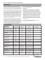
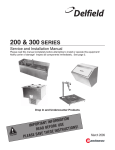
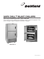
SAFE CHILL™ BLAST CHILLERS
Service, Installation and Care Manual
Please read this manual completely before attempting to install or operate this equipment! Notify
carrier of damage! Inspect all components immediately. See page 2.
Model DBC-10
EFFECTIVE JANUARY 2002
Safe Chill™ Blast Chillers Service & Installation Manual
Contents
Serial Number Information
RECEIVING AND INSPECTING UNIT.................................. 2
MECHANICAL DATA ............................................................. 2
INSTALLATION................................................................... 3-5
OPERATION.......................................................................... 5
CONTROL ............................................................................. 4
LIST OF PARAMETERS........................................................ 6
ROUTINE MAINTENANCE ................................................... 5
WIRING DIAGRAM ............................................................... 7
REPLACEMENT PARTS LIST............................................... 8
STANDARD WARRANTIES............................................ 10-11
AUTHORIZED PARTS DEPOTS ......................................... 12
On Delfield’s Safe Chill™ Blast Chiller units, the serial tag is
located on the right hand interior side of the top cabinet.
Always have the serial number of your unit available when
calling for parts or service. A complete list of authorized
Delfield parts depots is shown on the back cover of this
manual.
This manual ©2002 The Delfield Company. All rights reserved. Reproduction
without written permission is prohibited. Safe Chill™ and Delfield are registered
trademarks of The Delfield Company.
Receiving and Inspecting the Equipment
Care should be taken during unloading so the equipment is not
damaged while being moved into the building.
Carefully check for any visible signs of damage to the cartons
or containers. If evidence of damage exists, the package
should be opened immediately and a joint inventory and
examination of the contents should be made by you and the
driver.
Filing a claim
Notation of loss or damage does not constitute the filing of
a claim. You should file your claim in writing with the carrier
immediately.
Carriers will furnish the necessary form upon request. You
should also request an inspection. If a claim is filed by phone,
always follow up immediately in writing.
Concealed damage
If a concealed loss or damage is discovered after you have
given the carrier a clear delivery receipt, notify the carrier in
writing immediately or within 10 days from the delivery date.
If you phone the carrier, you must follow up the call in writing
to protect your rights. You can only improve your position as
a claimant by promptly reporting such loss or damage. You
should also retain all cartons or containers, including packing
material, until an inspection has been made or waived.
Safe Chill™ Blast Chiller
Mechanical Data
MODEL
NUMBER
DBC-5
DBC-5U
DBC-10
2
LENGTH
35.63
52.25
35.63
DEPTH
31.1
30.92
31.1
HEIGHT
47.50
32
70.50
# OF
PANS
5
5
10
HP
AMPS
REF CHG
3/4
11/120v
56 oz.
3/4
11/120v
56 oz.
(2)3/4 11 (120v/208-240v) (2) 56 oz.
BTU SYS
CAP
4000
4000
(2) 4000
For customer service, call (800) 733-8829, (800) 733-8821, Fax (989) 773-3210, www.delfield.com
NEMA
PLUG
5-20P
5-20P
14-20P
SHIP
WEIGHT
410
410
600
Safe Chill™ Blast Chillers Service & Installation Manual
Installation
Location
Be sure the location chosen has a floor strong enough to
support the total weight of the cabinet and contents. Reinforce
the floor if necessary to provide for maximum loading.
For the most efficient operation, be sure to provide good air
circulation inside and out.
Inside cabinet: Do not pack the equipment so full that air cannot
circulate.
Outside cabinet: Be sure that the unit has access to ample air.
Avoid hot corners and locations near stoves and ovens.
Installation note: Evaporator drains are also located to the right
of the evaporator housing and run to a condensate evaporator
pan. No external drains are needed as this is all self contained.
Drain lines need to be kept free from obstruction to allow for
proper water removal.
It is recommended that the unit be installed no closer than 2”
from any wall.
Leveling
A level cabinet looks better and will perform more efficiently
when the doors line up with the door frames properly, the
cabinet will not be subject to undue strain, and the corners of
the shelves will not move around on the supports. Use a level to
make sure the unit is level from front to back and side to side.
Stabilizing
All models are supplied on casters for your convenience, ease
of cleaning and mobility. It is very important, however, that the
cabinet be installed in a stable condition with the front wheels
locked while in use.
Should it become necessary to lay the unit on
its side or back for any reason, allow at least 24
hours before start-up so as to allow compressor
oil to flow back to the sump.
Electrical Connection
Refer to the amperage data on page 2, the serial tag, your
local code or the National Electrical Code to be sure the unit is
connected to the proper power source. A protected circuit of the
correct voltage and amperage must be run for connection of the
line cord, or permanent connection to the unit.
The unit should be disconnected from the
power source whenever performing service,
maintenance functions or cleaning the
refrigerated area.
Be careful - the line cord is not run over by the
casters when moving the unit. This can damage
the cord.
The unit comes standard with non adjustable casters, a level
floor is very important. If it becomes necessary to level the unit
adjustable legs are available.
Operation Information
(SEE PAGE 4 FOR DIAGRAM OF CONTROL PANEL)
Operating Pressures
Normal operating pressures should be achieved during
the preservation mode, with approximately 75 of ambient
temperature. Freezer mode 15# suction and 220# discharge.
Chilling mode 55# suction and 220# discharge.
Blast Chilling (soft mode): This mode pulls the food down from
the starting temperature to food set point of 37˚F (FP1). Once
the temperature is obtained the unit sounds an alarm and either
switches to preservation mode automatically (after the alarm
times out) or manually. During pull down in soft mode, the blast
chiller maintains a box temperature of 23˚F (BT1). This mode is
primarily used for pulling down delicate foods.
Blast Chilling (timed mode): This mode operates in either a
soft or hard mode. The user can preset the amount of time the
chiller pulls down for up to 240 minutes (TC1). The unit will
pull down until the time is reached or the two probes hit 37˚F
(FP1). At this point the unit will sound an alarm and go into
preservation mode.
Blast Chilling (hard mode): This mode operates the same way
as the soft mode except for the box temperature. During pull
down from start until one of the two food probes reaches 47˚F
(FP2) the box temperature is maintained at -5˚F (BT2), after
this point the box temperature is held at 23˚F (BT1) until the
food reaches 37˚F (FP1). This mode is for items that are harder
to pull down or if a faster chilling time is desired.
Preservation Mode: After any of the above cycles reach their
set point, the unit will go into a preservation mode. This mode
will be held until the user terminates it. After chilling, the
food probes will maintain a temperature of 37˚F (FP1) using
a box temperature of 23˚F (BT1). After the freezing, the food
probes will maintain a temperature of 0˚F (FP3) using a box
temperature of -15˚F (BT3).
Freezer Mode: This mode pulls the food down from starting
point to 0˚F (FP3). In this mode the unit operates in a hard chill
mode until one of the two food probes reach 37˚F (FP1). At that
point the box temperature is pulled down to -25˚F (BT3) until the
food set point of 0˚F (FP3) is reached. At this point an alarm is
sounded and the unit can go into preservation mode.
continued pg. 4
For customer service, call (800) 733-8829, (800) 733-8821, Fax (989) 773-3210, www.delfield.com
3
Safe Chill™ Blast Chillers Service & Installation Manual
Safe Chill™ Control
Probe
Temp
Box
Temp
OPERATION CONTINUED...
Time
Elapsed
Time
Remaining
Defrost Mode: After chilling/freezing the unit will go into a
defrost mode for 15 minutes or until the coil reaches a
temperature of 70˚(DF1). During the freezer preservation mode
the defrost heater will operate for 15 minutes (DF2) or until the
coil reaches a temperature of 70˚F(DF1) every 6 hours (DF3).
Tandem Mode (DBC-10 only): In this mode, both the upper
and lower compartments will start at the same time running in
the same mode of operation (soft, hard, or freezer mode). Once
operating the compartments cycle independently. For example,
if the bottom compartment pulls down quicker than the top it will
shut down without affecting the tops operation.
Individual Mode (DBC-10 only): This mode allows operation of
the two compartments in different modes of operation starting
them at different times. For example, the top compartment can
be loaded to run in a timed soft chill cycle, and at any time the
bottom could be loaded in a freezer mode and started.
Operating the Control
1. Start Cycle (DBC-10 will start both upper and lower
units):
• Press MODE button, display will change.
• Press MODE button until desired mode (soft, hard, freeze)
appears in left hand upper corner of display.
• Press START/STOP button, unit will start cycle.
2. Start cycle in individual mode (DBC-10 only):
• Press MODE button, display will change
• Press MODE button until “Indiv” appears in left hand upper
corner of display.
• Press ENTER button.
• Press MODE button until desired mode (soft, hard, freeze)
appears in left hand upper corner of display.
• Press START/STOP button, unit will start cycle.
3. Start cycle in timed mode (DBC-10 only will start both
upper and lower units):
• Press MODE button, display will change
• Press MODE button until “Indiv” appears in left hand upper
corner of display.
• Press TIMED button, counter will appear in right hand
upper corner of display.
• Press UP/DOWN buttons to adjust timer to desired setting.
• Press START/STOP button, unit will start cycle.
4. To stop a cycle:
• Press START/STOP button for one second.
If unit is a DBC-5 or DBC-5U cycle will shut down.
DBC-10 If only one compartment is running, cycle will shut
down. If both compartments are running, display will prompt
you to shut entire unit down by pressing START/STOP
button. To shut down the individual compartments press
the UP button for the top or the DOWN button for the
bottom.
Soft
Chill
4
Hard
Chill
Blast
Freeze
Dual
Mode
For customer service, call (800) 733-8829, (800) 733-8821, Fax (989) 773-3210, www.delfield.com
Safe Chill™ Blast Chillers Service & Installation Manual
OPERATION CONTINUED...
5. Start cycle with one unit running (DBC-10 only):
• Press MODE button, display will change.
• Press MODE button until desired mode (soft, hard, freeze)
appears in left hand upper corner of display.
Press START/STOP button, unit will start cycle.
6. Adjusting parameters (using this function will affect
performance and should only be carried out by qualified
personnel.):
• Press and hold UP and MODE buttons until menu changes
to system menu.
• Press UP/DOWN button until “Preset Menu” is highlighted.
• Press UP/DOWN button until parameter to be adjusted is
shown.
To edit press ENTER button
Press UP/DOWN button until new setting is displayed.
Press ENTER to save.
• Press START/STOP to back out to previous menu.
7. Setting Clock.
Skip first three steps if clock is being set from power startup
• Press and hold UP and MODE buttons until menu changes
to system menu.
• Press UP/DOWN button until “Clock setup” is highlighted.
• Press ENTER button to access Clock setup.
• Press UP/DOWN button until value to be adjusted is
highlighted.
• Press ENTER button to edit setting.
• Press UP/DOWN button until new setting is displayed.
• Press ENTER button to save setting.
• Repeat if additional settings require adjustment.
9. Alarms and Faults
The unit will sound an alarm upon the completion of a cycle
or if a fault occurs. The end of a cycle alarm is distinctively
different than the fault alarm. If a fault occurs an alarm will
sound and the display will prompt you to press the ENTER
button. The display will then show an explanation of the fault
that occurred. To end the fault message press START/STOP
button. This will repeat if there is more than one fault.
If the cycle that the fault occurred in is printed the print out
will place an “x” at the right hand side of the printout under
the letter that corresponds to that fault. See the list below for
the fault and its equivalent letter.
A ......... Product Probe #1 open
B ......... Product Probe #1 shorted
C ......... Product Probe #2 open
D ......... Product Probe #2 shorted
E ......... Box temperature sensor open
F ......... Box temperature sensor shorted
G ......... Defrost temperature sensor open
H ......... Defrost temperature sensor shorted
I ......... Chill cycle time exceeded
J ......... Food temperature below limit
K ......... Power interrupted cycle
8. Printing
Print parameter (PR1) must be set to OFF (default) for unit
to print after cycle is complete. If PR1 is set to ON unit will
download information at the print intervals (PT1).
Information is downloaded to printer using the RS-232 port
under the touch pad. If information is to be downloaded to a
PC a crossed RS-232 cable must be used.
Unit will only print to an 80 character wide printer.
• The following instructions are for printing after cycle is
complete (PR1 set to OFF).
• For DBC-5 and DBC-5U press the PRINT button and unit
will begin downloading information. Print function will only
work if the selected units cycle is completed.
• Control only saves information from previous cycle; once a
new cycle is started the previous information is deleted.
For customer service, call (800) 733-8829, (800) 733-8821, Fax (989) 773-3210, www.delfield.com
5
Safe Chill™ Blast Chillers Service & Installation Manual
MAINTENANCE
The interior and exterior can be cleaned using soap and warm
water. If this isn’t sufficient, try ammonia and water or a
nonabrasive liquid cleaner. When cleaning the exterior, always
rub with the “grain” of the metal to avoid marring the finish. Do
not use an abrasive cleaner because it will scratch the metal.
In order to maintain proper refrigeration performance, the condenser fins must be cleaned of dust, dirt and grease regularly.
The condenser coil is located behind the removable louvered
front and there are two coils located on the DBC-10. It is
recommended that these be cleaned at least once every three
months. If conditions are such that the condenser is totally
blocked in three months, the frequency of cleaning should
be increased. Clean the condenser with a vacuum cleaner
or stiff brush. If it’s extremely dirty, a commercially available
condenser cleaner may be required.
Door gaskets are dart style and can easily be replaced without
the use of any tools. Do not use sharp tools or knives to
scrape the bellows as this may tear the gasket and eliminate
its ability to seal. Door gaskets should be cleaned as required
to maintain their ability to seal properly. A soft bristle brush
and solution of soap and water will keep the gaskets clean. Do
not use full strength de-greasing agents on the gasket.
Pan slides are removable via the four thumb screws and are
made of stainless steel. They are dishwasher safe or can be
cleaned with soap and water.
Food Probes:
If necessary to check the probes, they are a 10,000 ohm
thermistor and it is important that they be kept away from
any high voltage wiring. There are four probes per section;
two food probes, one box probe and an evaporator probe.
Accessing the evaporator, expansion valve, and other evaporator components can be done by removing the pan slides and
pulling the evaporator housing away slowly as to not pull out
any wiring. Once access has been gained wire ties can be
cut and the housing can be removed. Food probes can be
cleaned with soap and water. For optimum use of the food
probes, do not allow the handle to rest in the food. When
removing a food probe from the food do not pull on the cable,
use the handle.
The control uses a lithium battery and may need to be
replaced approximately every five years.
List of Parameters
PARAMETER
DESCRIPTION
Food probe
temperature (chilling)
PARAMETER
DEFAULT
RANGE
(FP1)
37˚F
28˚F to 40˚F
Food probe
temperature (hard chilling)
(FP2)
47˚F
0˚F to 70˚F
Food probe
temperature (freezing)
(FP3)
0˚F
-20˚F to 10˚F
Box temperature
(soft/hard chilling)
(BT1)
23˚F
20˚F to 37˚F
Box temperature
(hard chilling)
(BT2)
-5˚F
20˚F to 37˚F
Box temperature
(freezing hold)
(BT3)
-15˚F
-5˚F to -30˚F
Maximum chill time
(TC1)
240 minutes
0 to 240 minutes
Defrost termination
(temperature)
(DF1)
55˚F
40˚F to 70˚F
Defrost termination (time)
(DF2)
15 minutes
0 to 90 minutes
Defrost cycle time
(freezing)
(DF3)
360 minutes
180 to 480 minutes
Print output
(PR1)
(PR1)
OFF to PR1
Print interval
(PT1)
5 minutes
0 to 480 minutes
Maximum coil temperature
(evaporator fan)
(MCT)
30˚F
20˚F TO 60˚F
Chill time recall
(CTR)
Recall
0 to chill time alarm
(TC1)
6
For customer service, call (800) 733-8829, (800) 733-8821, Fax (989) 773-3210, www.delfield.com
COMMENTS
Stores last chill
time /or preset
Safe Chill™ Blast Chillers Service & Installation Manual
Wiring Diagram
For customer service, call (800) 733-8829, (800) 733-8821, Fax (989) 773-3210, www.delfield.com
7
Safe Chill™ Blast Chillers Service & Installation Manual
8
For customer service, call (800) 733-8829, (800) 733-8821, Fax (989) 773-3210, www.delfield.com
Safe Chill™ Blast Chillers Service & Installation Manual
Notes:
For customer service, call (800) 733-8829, (800) 733-8821, Fax (989) 773-3210, www.delfield.com
9
Safe Chill™ Blast Chillers Service & Installation Manual
Standard One Year Warranty
One year service, labor and parts.
The Delfield Company (“Delfield”) warrants to the Original
Purchaser of the Delfield product (herein called the “Unit”) that
such Unit, and all parts thereof, will be free from defects in
material and workmanship under normal use and service for
a period of one (1) year from the date of shipment of the Unit
to the Original Purchaser or, if the Original Purchaser returns
the warranty card completely filled out including the date of
installation within thirty (30) days of receipt of the Unit, one
(1) year from the date of installation. During this one year warranty period, Delfield will repair or replace any defective part or
portion there of returned to Delfield by the Original Purchaser
which Delfield determines was defective due to faulty material
or workmanship. The Original purchaser will pay all labor,
crating, freight and related costs incurred in the removal of the
Unit of defective component and shipment to Delfield, except
that during a period of either ninety (90) days from the date
of shipment of the Unit to the Original Purchaser or if, the
Original Purchaser returns the warranty card completely filled
out including the date of installation within thirty (30) days of
receipt of the Unit, ninety (90) days from the date of installation
Delfield will pay all related labor costs. Delfield will pay the
return costs if the Unit or part thereof was defective.
The term “Original Purchaser” as used herein means that
person, firm, association, or corporation for whom the Unit was
originally installed.
This warranty does not apply to any Unit or part thereof
that has been subjected to misuse, neglect, alteration, or accident, such as accidental damage to the exterior finish, operated contrary to the recommendations specified by Delfield;
or repaired or altered by anyone other than Delfield in any
way so as to, in Delfield’s sole judgement, affect its quality or
efficiency. This warranty does not apply to any Unit that has
been moved from the location where it was originally installed.
This warranty also does not cover the refrigerator drier or the
light bulbs used in the Unit. The warranty is subject to the
user’s normal maintenance and care responsibility as set forth
in the Service and Installation Manual, such as cleaning the
condenser coil, and is in lieu of all other obligations of Delfield.
Delfield neither assumes, nor authorizes any other person
to assume for Delfield, any other liability in connection with
Delfield’s products.
Removal or defacement of the original Serial Number or Model
Number from any Unit shall be deemed to release Delfield
from all obligations hereunder or any other obligations, express
or implied.
Parts furnished by suppliers to Delfield are guaranteed by
Delfield only to the extent of the original manufacturer’s
express warranty to Delfield.
Failure of the Original Purchaser to receive such manufacturers warranty shall in no way create any warranty, expressed
or implied, or any other obligation or liability on Delfield’s part
in respect thereof.
10
If shipment of a replacement part is requested prior to the
arrival in the Delfield factory of the part claimed to be defective,
the Original Purchaser must accept delivery of the replacement part on a C.O.D. basis, with credit being issued after the
part has been received and inspected at Delfield’s plant and
determined by Delfield to be within this warranty.
Under no condition does this warranty give the Original Purchaser the right to replace the defective Unit with a complete
Unit of the same manufacturer or of another make. Unless
authorized by Delfield in writing, this warranty does not permit
the replacement of any part, including the motor-compressor,
to be made with the part of another make or manufacturer.
No claims can be made under this warranty for spoilage of any
products for any reason, including system failure.
The installation contractor shall be responsible for building
access, entrance and field conditions to insure sufficient clearance to allow any hood(s), vent(s), or Unit(s) if necessary, to
be brought into the building. Delfield will not be responsible for
structural changes or damages incurred during installation of
the Unit or any exhaust system.
Delfield shall not be liable in any manner for any default
or delay in performance hereunder caused by or resulting
from any contingency beyond Delfield’s control, including, but
not limited to, war, governmental restrictions or restraints,
strike, lockouts, injunctions, fire, flood, acts of nature, short or
reduced supply of raw materials, or discontinuance of the parts
by the original part manufacturer.
Except as provided in any Additional Four Year Protection
Plan, if applicable, and the Service Labor Contract, if applicable, the foregoing is exclusive and in lieu of all other warranties, whether written or oral, express or implied. This warranty
superseded and excludes any prior oral or written representations or warranties. Delfield expressly disclaims any implied
warranties of merchantability, fitness for a particular purpose
of compliance with any law, treaty, rule or regulation relating
to the discharge of substances into the environment. The sole
and exclusive remedies of any person relating to the Unit, and
the full liability of Delfield for any breach of this warranty, will be
as provided in this warranty.
Other than this Delfield Standard One Year Limited Warranty,
any applicable Delfield Additional Four Year Protection Plan
or applicable Delfield Service Labor Contract, the Original
Purchaser agrees and acknowledges that no other warranties
are offered or provided in connection with or for the unit or any
other part thereof.
In no event will Delfield be liable for special, incidental or
consequential damages, or for damages in the nature of penalties.
For customer service, call (800) 733-8829, (800) 733-8821, Fax (989) 773-3210, www.delfield.com
Safe Chill™ Blast Chillers Service & Installation Manual
Additional Four Year Protection Plan (for Motor-Compressors only)
Delfield Model#
Serial #
Installation
Date
In addition to the Standard One Year Warranty on the MotorCompressor contained in the above listed Delfield product
(the “Unit”), The Delfield Company (“Delfield”) also agrees to
repair, or exchange with similar or interchangeable parts in
design and capacity at Delfield’s option, the defective MotorCompressor contained in the Unit (the “Motor-Compressor),
or any part thereof, for the Original Purchaser only, at any
time during the four (4) years following the initial one (1) year
period commencing on the date of installation for the Original
Purchaser. Failure of the Original Purchaser to register the
registration card containing the Original Purchasers name,
address, date of installation, model number and serial number
of the Unit containing the Motor-Compressor within 30 days
from the date of installation shall void this warranty. This
additional warranty is only available if the Motor-Compressor is
inoperative due to defects in material or factory workmanship,
as determined by Delfield in its sole judgement and discretion.
The Original Purchaser shall be responsible for returning the
defective Motor-Compressor to Delfield prepaid, F.O.B. at the
address shown on the back cover of this manual.
The term “Original Purchaser” as used herein means that
person, firm, association, or corporation for whom the Unit was
originally installed.
The term “Motor-Compressor” as used herein does not include
unit base, air or water cooled condenser, receiver, electrical
accessories such as relay, capacitors, refrigerant controls, or
condenser fan/motor assembly. This warranty does not cover
labor charges incidental to the replacement of parts. This
warranty further does not include any equipment to which said
condensing unit is connected, such as cooling coils, temperature controls or refrigerant metering devices. This warranty
shall be void if the Motor-Compressor, in Delfield’s sole judgement, has been subjected to misuse, neglect, alteration or
accident, operated contrary to the recommendations specified
by the Unit manufacturer, repaired or altered by anyone other
than Delfield in any way so as, in Delfield’s sole judgment, to
affect its quality or efficiency or if the serial number has been
altered, defaced or removed. This Warranty does not apply
to a Motor-Compressor in any Unit that has been moved from
the location where it was originally installed. The addition of
methyl chloride to the condensing unit or refrigeration system
shall void this warranty.
General Conditions
Delfield shall not be liable in any manner for any default
or delay in performance hereunder caused by or resulting
from any contingency beyond Delfield’s control, including, but
not limited to, war, governmental restrictions or restrains,
strike, lockouts, injunctions, fire, flood, acts of nature, short or
reduced supply of raw materials, or discontinuance of any part
or the Motor-Compressor by the unit manufacturer.
Replacement of a defective Motor-Compressor is limited to
one (1) Motor-Compressor by us during the four (4) year
period. Delfield shall replace the Motor-Compressor at no
charge.
This warranty does not give the Original Purchaser of the
Motor-Compressor the right to purchase a complete replacement Motor-Compressor of the same make or of another
make. It further does not permit the replacement to be made
with a Motor-Compressor of another kind unless authorized
by Delfield. In the event Delfield authorizes the Original Purchaser to purchase a replacement Motor-Compressor locally,
only the wholesale cost of the Motor-Compressor is refundable.
Expressly excluded from this warranty are damages resulting
from spoilage of goods.
Except as provided in any applicable Standard One Year Limited Warranty or applicable Service Labor Contract, the foregoing is exclusive and in lieu of all other warranties, whether
written or oral, express or implied. This Warranty supersedes
and excludes any prior oral or written representations or warranties. Delfield expressly disclaims any implied warranties of
merchantability, fitness for a particular purpose or compliance
with any law, treaty, rule or regulation relating to the MotorCompressor, and the full liability of Delfield for any breach of
this warranty, will be as provided in this warranty.
Other than any applicable Delfield Standard One year Limited
Warranty, this Delfield Additional Four Year Protection Plan and
any applicable Delfield Service Labor Contract, the Original
Purchaser agrees and acknowledges that no other warranties
are offered or provided in connection with or for the MotorCompressor or any part thereof.
In no event will Delfield be liable for special, incidental or
consequential damages, or for damages in the nature of penalties.
For customer service, call (800) 733-8829, (800) 733-8821, Fax (989) 773-3210, www.delfield.com
11
Delfield Authorized Parts Depots
DMDBC 01/02