1
(without price)
Pocket Manager
BE-300 (JX-740A)
SEP. 2001
BE-300
INDEX
R
CONTENTS
1. MAIN FEATURES ------------------------------------------------------------------------------- 1
2. SPECIFICATIONS ------------------------------------------------------------------------------- 2
3. ACCESSORIES AND OPTIONS ------------------------------------------------------------ 4
3-1. Bundled products and parts -------------------------------------------------------- 4
3-2. New options ------------------------------------------------------------------------------ 4
3-3. The other options: ---------------------------------------------------------------------- 4
4. GENERAL GUIDE ------------------------------------------------------------------------------- 5
5. RESET OPERATION AND INITIAL SETUP -------------------------------------------- 25
6. BBUILT-lN BATTERY PACK AND BATTERY REPREPLACEMENT------------ 28
6-1. Built on Battery Pack ---------------------------------------------------------------- 28
6-2. Battery Replacement ---------------------------------------------------------------- 28
7. DATA COMMUNICATIONS ----------------------------------------------------------------- 29
7-1. General ------------------------------------------------------------------------------------ 29
7-2. PC Connect software ----------------------------------------------------------------- 31
7-3. Back Up and Restore ---------------------------------------------------------------- 34
8. DIAGNOSTIC PROGRAM AND OPERATION CHECK ----------------------------8-1. Diagnostic Program -----------------------------------------------------------------8-2. To enter into Operation Check --------------------------------------------------8-3. Operation Check ----------------------------------------------------------------------
45
45
45
50
9. TROUBLESHOOTING ----------------------------------------------------------------------- 57
10. CIRCUIT BLOCK DIAGRAM --------------------------------------------------------------- 63
11. SHEMATIC DIAGRAMS --------------------------------------------------------------------11-1. MAIN PC BOARD ASSEMBLY (1/2) ---------------------------------------------11-2. MAIN PC BOARD ASSEMBLY (2/2) ---------------------------------------------11-3. CRADLE ----------------------------------------------------------------------------------
64
64
65
66
12. PCB VIEW --------------------------------------------------------------------------------------- 67
13. DISASSEMBLY PROCEDURE ------------------------------------------------------------ 69
14. PARTS LIST ------------------------------------------------------------------------------------ 75
15. EXPLODED VIEW ----------------------------------------------------------------------------15-1. PCB ASSY/MAIN (1/2) --------------------------------------------------------------15-2. PCB ASSY/MAIN (2/2) --------------------------------------------------------------15-3. INNER CASE ASSY, HARD COVER ASSY AND COMPONENTS ------15-4. OTHERS ----------------------------------------------------------------------------------
* Windows is a registered trademark of Microsoft Corporation in the U.S.A. and other countries.
* i486 and Pentium are registered trademarks of Intel Corporation.
77
77
78
79
80
1. MAIN FEATURES
BE-300 is a smaller and lighter CASSIOPEIA PDA compared with the prior ones.
The main features on hardware are as follows;
1. Higher speed CPU: VR4131 166MHz (280MIPS) *MIPS: Million Instructions Per Second
2. 16MB FLASH ROM/ SDRAM (Synchronous Dynamic RAM):
NAND Type Flash ROM/ SDRAM are mounted on the main PC Board instead of ROM PC Board.
Therefore, there are no ROM PC Board and Lithium battery for backup in BE-300.
Note that once operating the user’s unit, the saved data by this operation are not deleted even if
removing the battery pack and AC adapter. After reset operation and initialization, these saved data
can not be deleted.
If you want to reserve user’s data for repair, firstly, perform the backup operation without operating
user’s unit. Refer to 7-4. Backup and Restore in this manual concerning the backup.
3. New options (PC Card Unit:JK-865PU/ External Power Pack: JK-215LT etc.)
Battery Life is shorter, approximately half time, compared with the prior CASSIOPEIA PDAs as
described below.
6 hours (Continuous input and data display at a ratio of 1:10)
In case of E-125, Battery Life is 8 hours.
It is recommended to use External Power Pack JK-215LT to make Battery Life longer.
Using this power pack, 15 hours with continuous operation may be realized.
Using PC Card Unit, various kinds of PCMCIA Type II Cards can be used.
4. A Flip Cover which is easier to replace is assembled to protect the touch screen panel.
There are no flip hard covers in the prior CASSIOPEIA PDAs.
5. STN Color LCD (32,768 colors) instead of TFT Color LCD
Eight kinds of color display variations (Standard, Herb, Horizon and so on)
6. No record/ play operation using microphone (No microphone)
There is no microphone in BE-300.
The main features on software are as follows;
1. Original API (Application Program Interface):
BE-300 supports the standard Win32API for Palm size PC API.
However, BE-300 doesn’t support Pocket PC API.
2. New communication software with PC: PC Connect
Refer to 7-2. PC Connect software in this manual for detail.
3. OS, the standard applications, additional application and user data (7MB) are stored in NAND type
Flash ROM (16MB).
The standard applications for PIM etc. can be easily deleted.
However, these applications can be easily installed again using PC Connect and these software in the
bundled CD-ROM.
4. The standard applications size for PIM etc. are compressed compared with the prior
CASSIOPEIA PDAs.
Note:
BE-300 can not drive Micro Drive because Micro Drive consumes too much power, and voltage
detectors and protection functions in circuitry of BE-300 will work by too much power. At last, BE300 will be turned off.
* For other information, refer to the bundled CD-ROM and world. CASIO. com Web Site.
—1—
2 . SPECIFICATIONS
Model:
Display:
BE-300
240 x 320 dots
STN Color LCD(32,768colors)
CPU:
VR4131 166MHz(280MIPS)
Memory :
ROM 16MB Flash ROM ( NAND Type,User 7MB)
SDRAM 16MB
OS:
Microsoft Windows CE3.0
Interfaces:
Serial:RS-232C,115.2 kbps max.
USB(Client)
Card Slot:
Compact Flash card, 3.3V Type I/TypelI
Headphone jack:
ø 3.5 mm stereo output
Accepts monaural earphone,stereo earphones/headphones
Power Supply :
Rechargeable battery (Lithium-Ion battery)
AC adapter (AD-C59200)
Power Consumption: 3.0W
Current consumption:
Note :
1. When measuring these current, it is recommended to use the analog ammeter to protect the ammeter
from noises.
2. Make LCD display contrast best condition before measurement.
3. Measure under the ambient temperature range 15˚~35˚C.
Operation Mode
Input Voltage
Current Consumption
Main Menu of OPERATION
CHECK
Rechargeable Battery :
4.0 ± 0.1V
≤180mA
POWER CONTROL of
OPERATION CHECK
Rechargeable Battery :
4.0 ± 0.1V
≤400mA
POWER CONTROL of
OPERATION CHECK
AC Adapter :
5.9 ± 0.1V
≤400mA
Power/OFF
Rechargeable Battery :
4.0 ± 0.1V
≤1.6mA
* Refer to 8. DIAGNOSTIC PROGRAM AND OPERATION CHECK in this manual concerning
OPERATION CHECK.
* Tapping 5 POWER CONTROL in the operation check main menu display, the following display will
appear.
Currency CPU is
165 MHZ
VTClook is
82 MHZ
Push Action key to exit
Power supply voltage detection:
approximately 3.65V ± 5% (Internal Battery Warning / Low battery message)
approximately 3.40V ± 1% (Forced power OFF)
—2—
Once Internal Battery Warning message appear, this message will not be disappeared even if the power
supply voltage becomes higher again.
It is recommended to perform RESET operation after replacing or charging the battery as soon as possible.
* Internal Battery Warning message is as follows;
The internal battery is low. Continued use may result in loss of ability to store data. Charge the battery
as soon as possible.
Warning: After the battery goes to tally dead, it takes about 10 minutes of charging before the unit is
available again.
Approximate Battery Life (Normal Temperature)
(Actual time may be shorter due to conditions when charging.)
1 week: Based on normal use
6 hours: Continuous input and data display at a ratio of 1 : 10, with screen brightness at
lowest possible level.
• Even when the unit is turned off, small amounts of power are required to retain memory
contents, etc. This can cause batteries to go dead even when you do not use the unit.
• The actual amount of operation time that can be expected from batteries depends on
operating conditions, settings, and other variables.
Approximate Charge Time (Normal Temperature)
3 to 4 hours: Charge time is longer for the first charges after purchasing the unit or installing
a new battery pack.
Operating Temperature: 0˚C to 40˚C (32˚F to 104˚F)
Charging Temperature: 10˚C to 35˚C (50˚F to 95˚F)
Dimensions: 17.9 H x 76.0 W x 121.0 D mm (3/4"H x 3"W x 4 3/4"D) (Excluding cover and projections.)
Weight: Approximately 170 g (6.0 oz) (Including cover.)
Approximately 158 g (5.6 oz) (Excluding cover.)
—3—
3. ACCESSORIES AND OPTIONS
3-1. Bundled products and parts
Refer to OTHERS in14. PARTS LIST and 15. EXPLODED VIEW in this manual concerning the bundled
products and parts.
3-2. New options
1. External Power Pack: JK-215LT
2. PC Card Unit: JK-865PU
3. BE-300 Replacement Flip Cover: JK-870FC
This cover can be supplied as one of the spare parts.
Refer to item 20 in PARTS LIST and EXPLODED VIEW in this manual concerning this flip hard cover.
4. Stylus Replacement: JK-825ST (2 per pack)
This stylus can be supplied as one of the spare parts also.
Refer to item 19 in PARTS LIST and EXPLODED VIEW in this manual concerning this stylus.
5. 5-Pack of Screen Protectors: JK-835PS5
Refer to Accessory Catalog in the bundled CD-ROM (item 30 in PARTS LIST of this manual) as shown
below.
3-3. The other options:
Refer to Accessory Catalog and Partner’s Catalog in the bundled CD-ROM (item 30 in
PARTS LIST of this manual) as shown below.
—4—
4. GENERAL GUIDE
Charge indicator (Amber)
Lights amber when the battery pack
is charging and goes off when full
charge is achieved.
Card slot
Stylus
Strap hole
Fixed IconS
Tap an icon to launch the
program assigned to it.
See the CASSIOPEIA
User's Guide for details.
Touch screen
Perform operations
and input data by
tapping and writing
directly on the screen.
Power button
Turns power on and off.
Top Menu button
Press to display the Top
Menu. See the
CASSIOPEIA User's
Guide for details.
Stereo headphone jack
For connection of
commercially available
earphone/headphones
(ø3.5mm).
OK button
Same as a computer's
ENTER key
AC adapter terminal
ESC button
Same as a computer's
ESC key
Cursor button
Moves the cursor around the
screen.
Reset button
Serial Connector
For connection of the cradle or the
CASSIOPEIA USB cable.
—5—
Removing the cover
Gently pull outwards on either of the cover hinges indicated by the arrows in the illustration until the hinge
is free, and then remove the cover. Make sure you do not apply excessive force when removing the cover.
Recalibrating the Touch Screen
You should recalibrate the touch screen whenever touch screen response is bad, or when the operation
performed is different from the operation you expected when tapping on the touch screen.
To recalibrate the touch screen, press the [OK] button while holding down the [Power] button. Next, follow
the instructions that appear on the screen.
Adjusting Display Contrast
Perform either of the following operations to adjust display contrast and make figures on the display darker
or lighter.
• Press the [Top Menu] button to display the Top Menu, and then tap Settings -Brightness. Follow the
instructions on your screen for adjusting the contrast.
• You can also adjust contrast as follows.
To do this:
Do this:
Make contrast darker
Hold down the [Power] button as you press the up
[Cursor] button
Make contrast lighter
Hold down the [Power] button as you press the down
[Cursor] button
Adjusting Display Brightness
Use the following operations to adjust display brightness to make it easier to read.
1. Press the [Top Menu] button to display the Top Menu, and then tap Settings -Brightness .
2. On the dialog box that appears, tap the Brightness tab.
3. Follow the instructions that appear on the screen for adjusting the brightness.
• You can also adjust brightness as follows.
To do this:
Do this:
Make the screen brighter
Hold down the [Power] button as you press the right [Cursor] button
Make the screen dimmer
Hold down the [Power] button as you press the left [Cursor] button
—6—
Adjusting Auto Dimming Settings
1. Press the [Top Menu] button to display the Top Menu, and then tap Settings -Brightness .
2. On the dialog box that appears, tap the Auto Dim tab.
3. Follow the instructions that appear on the screen to make auto dimming settings.
• You can make separate auto dimming settings for internal power (battery power) and external
power (AC adapter and optional large-capacity External Power Pack) by checking the appropriate
check box.
Using the Cradle
The cradle provides quick and easy connection between your CASSIOPEIA and a computer.
Your CASSIOPEIA can also be powered from an AC power source when it is placed on the cradle.
• The battery pack charges while the CASSIOPEIA is on the cradle. See page 32 for more information.
Important
Before connecting your CASSIOPEIA to a computer, make sure you first install the PC Connect software
on your computer.
Changing the Cradle Configuration
The cradle has a back board which you can set to any one of the three positions shown in the illustration
below. Use the position that suits the configuration of the CASSIOPEIA unit you are setting on the cradle.
CASSIOPEIA + PC Card Unit
CASSIOPEIA + External Power Pack
CASSIOPEIA Only
Important
Make sure that CASSIOPEIA power is turned off before you place it onto or remove it from the cradle.
Use the following procedure to place the unit onto the cradle.
1. Place the cradle on a desk or other flat level surface.
2. Turn off the CASSIOPEIA.
3. Remove the CASSIOPEIA's Serial connector cover to open it.
—7—
4. Orient the CASSIOPEIA in relation to the cradle as shown in the illustration below.
5. Taking care to align the serial connector on the bottom of the CASSIOPEIA with the connector on the
cradle, Iower the CASSIOPEIA into the cradle as shown in the illustration below.
Important
• Make sure the CASSIOPEIA Iowers securely into the cradle as far as it can go.
• While the CASSIOPEIA is on the cradle, take care to keep its serial connector cover in a safe place.
Also, make sure you replace the serial connector cover when you remove the CASSIOPEIA from the
cradle.
To remove the CASSIOPEIA from the cradle
Lift the CASSIOPEIA straight up from the cradle.
—8—
Connecting the Cradle to a Computer
The cradle has a USB cable for connection to a computer. Connect the end of the cable to a USB port of the
computer to which you want to connect.
Important
USB port
• The above illustration is one example of possible connection configurations. The locations and layouts
of USB ports vary from computer to computer. See the documentation that comes with your computer
for full details on connecting cables to it.
• Note that after connecting the cradle to your computer, you also need to make certain PC Connect
software settings on your computer to enable data transfers.
Using the CASSIOPEIA USB Cable
You can use the CASSIOPEIA USB cable to connect the CASSIOPEIA directly to a computer.
Important
• The illustration below is just one possible connection configuration. The location and layout of USB
ports vary from computer to computer. See the documentation that comes with your computer for full
details on connecting cables to it.
• You must have PC Connect software installed on your computer in order to exchange data with the
CASSIOPEIA over a USB connection.
TO Connect to a computer using the CASSIOPEIA USB cable
Important
Before connecting your CASSIOPEIA to a computer, make sure you first install the PC Connect software
on your computer. Use the steps below to connect the CASSIOPEIA to your computer when prompted
to do so during the software installation procedure.
1. Plug the USB cable into the USB port of your computer.
2. Turn off your CASSIOPEIA.
3. Connect the other end of the USB cable to your CASSIOPEIA.
USB port
CASSIOPEIA USB cable
—9—
Using the CASSIOPEIA Serial Cable
You can use the CASSIOPEIA serial cable to connect the CASSIOPEIA directly to a
computer.
Important
• Be sure to turn off the CASSIOPEIA and your computer before connecting the CASSIOPEIA.
• The illustration below is just one possible connection configuration. The location and layout of serial
ports vary from computer to computer. See the documentation that comes with your computer for full
details on connecting cables to it.
• You must have PC Connect software installed on your computer in order to exchange data with the
CASSIOPEIA over a serial connection.
Using a PC Card Unit
Connecting your CASSIOPEIA to an optional PC Card Unit (JK-865PU) makes it possible for you to use
PCMCIA card type PC cards with your CASSIOPEIA.
Important
• The PC Card Unit has a built-in lithium battery that provides power to the PC card. It comes with an
AC adapter that can be used to charge its built-in battery or to connect to a wall outlet for power
supply. See the user documentation that comes with the PC Card Unit for details about the built-in
battery and the AC adapter.
To connect your CASSIOPEIA to the PC Card Unit
1. Make sure your CASSIOPEIA is turned off.
• Press the [Power] button to turn off power.
2. If there is already a card in the slot, remove it.
3. Slide your CASSIOPEIA onto the PC Card Unit as shown in the illustration below.
• Make sure the CompactFlash card connector of the PC Card Unit slides into the CASSIOPEIA card
slot as far as it will go. This causes the CASSIOPEIA to lock in place on the PC Card Unit.
Remark
When using JK-865PU PC card Unit after connecting to BE-300, BE-300 may be turned off without warning,
or may be unable to be operated by strong static electricity.
When these symptoms occur, try to turn on BE-300 again, perform RESET operation for BE-300, or
connect PC Card Unit to BE-300 again after disconnecting.
For other information, refer to TROUBLESHOOTING in this manual.
— 10 —
To remove the CASSIOPEIA from the PC Card Unit
1. Make sure your CASSIOPEIA is turned off.
• Press the [Power] button to turn off power.
2. Pulling on your CASSIOPEIA in the direction indicated by the arrow in the illustration, remove it from
the PC Card Unit.
About the CASSIOPEIA's built-in rechargeable battery
Note the following precautions concerning the CASSIOPEIA's rechargeable battery.
• We recommend that you use the Power dialog box to keep informed about the current for more levels
of your battery. See the next "System Tray" for more information about this dialog box.
• lcons appear along the bottom of the screen to let you know when battery power is low. See the next
"System Tray" for more information about these icons.
System Tray
The System tray is always on the display, below the CASSIOPEIA touch screen.
(1)
(2)
(3) (4)
(5)
(1) Program Status Indicators
• These icons show the status of any programs you currently have running. This area can show up to 30
icons at one time.
• If all the icons cannot fit in the space provided, tap the
button on the right to scroll the icons and
view those that do not fit.
Important
is displayed in the system tray while your CASSIOPEIA is accessing memory. Following are precautions
you should observe whenever
is in the system tray.
•
•
•
•
Do not press the reset button.
Do not eject a card from the CASSIOPEIA.
Do not connect cables to or disconnect cables from the CASSIOPEIA.
Do not turn off CASSIOPEIA power.
— 11 —
(2) System Status Indicators
These icons provide information about the system. Tapping an icon displays one of the setting
screens described below.
This icon:
Means this:
And displays this screen when tapped:
The card slot contains a card. This icon
appears when the PC Card Unit is
attached to your CASSIOPEIA.
CF Slot Information dialog box
Dial up connection is in progress.
Current dial up connection status
CASSIOPEIA is running under external
power.
Power Management screen
Built-in battery is being charged.
Built-in battery is fully charged.
Built-in battery is sufficiently charged.
Built-in battery is low.
Built-in battery is extremely low.
The system is checking the power supply
status. This icon appears only for a few
seconds after you turn on power.
(3) Input panel button
Tap to display or hide the input panel.
(4) Input panel switch
Tap to display a list of input methods.
(5) Clock
Displays the current time (Home City time or Destination city time). Tapping the time displays
the Clock screen.
Low Battery Warning and Data Storage
• The following message appears whenever battery power drops below a certain level.
Recharge the battery as soon as possible after the following message appears.
"Internal Battery Warning
The internal battery is low. Continued use may result in loss of ability to store data. Charge the
battery as soon as possible."
• Whenever the low battery warning message appears, especially if it appears right after you turn on
power, follow the instructions that appear on the screen and recharge the battery as soon as possible.
Continued use under low battery power can cause unstable performance of your CASSIOPEIA.
If unit power turns off due to insufficient power, the following warning message
appears on the display the next time you turn on unit power.
"Warning
The system has shut down without warning to protect memory contents, due to
high electrical current consumption by hardware..."
— 12 —
If unit power turns off due to sudden power drain by a CompactFlash card, the following warning message
appears on the display the next time you turn on unit power.
" Warning
The system has shut down without waring to protect memory contents, due to high electrical current
consumption by the card..."
Important
Be sure to observe the following important battery handling precautions. Failure to do so can cause batteries
to leak, resulting in damage to surrounding items and create the danger of fire and electrical shock.
• Charge the battery pack in an area where the temperature is between 10˚C (50˚F) and 35˚C (95˚F).
Charging in areas that are very cold or exposed to direct sunlight can cause deterioration and leaking
of the battery pack.
• To avoid deterioration and leaking, the battery pack is designed to discharge even when you do not
use the CASSIOPEIA. Be sure to recharge the battery pack at least once a month,
regardless of how much you use the CASSIOPEIA during that time.
Charging the Battery Pack
Attach the AC adapter to the cradle and place the CASSIOPEIA onto the cradle.
USA Type (Refer to PARTS LIST and EXPLODED VIEW
in this manual concerning the other AC adapters.)
•
•
•
•
Charging starts automatically as soon as you place the CASSIOPEIA onto the cradle.
The charge indicator is red while charging is in progress. and goes off when charging is complete.
It takes about three or four hours to reach full charge.
You can use your CASSIOPEIA while the battery pack is charging.
Important
• Do not use the CASSIOPEIA while it is charging for the first time after you purchase it.
• If the battery does not achieve full charge after the normal charge time, unplug the AC adapter from
the cradle to stop charging.
Note :
The battery Pack for spare part will be about 30% charged. Therefore, charging this battery pack by AC
adapter is needed after assembling this battery Pack.
— 13 —
Remove the CASSIOPEIA from the cradle after charging is complete.
The following illustration shows how to connect the AC adapter directly to the CASSIOPEIA for charging.
USA Type (Refer to PARTS LIST and EXPLODED VIEW
in this manual concerning the other AC adapters.)
• Charging starts automatically as soon as you attach the AC adapter to the CASSIOPEIA.
• Direct connection charging conditions are the same as those described for cradle charging above.
Uninstalling Programs
You can uninstall programs you do not use in order to free up memory space. Note that you can uninstall the
following programs only.
• Programs you install in main memory or onto a storage card.
• Programs that come pre-installed in main memory, EXCEPT FOR Clock, Settings, Connections and
Backup.
To uninstall a program
1. On the Top Menu, tap the program you want to uninstall.
• You can skip the above step if the name of the program you want to uninstall is already highlighted.
2. Tap Edit
Delete Application.
3. In response to the confirmation message that appears, tap Yes to uninstall the program or No to
cancel without uninstalling anything.
Note:
• If you later need a program, you can re-install it from the bundled CD-ROM. See PC Connect online
help in User's Guide for more information.
Assigning a Program to the Icon Menu
You can use the following procedure to assign a program to the far right icon menu icon.
To assign a program to the icon menu
l . On the Top Menu, tap the program you want to assign to the icon.
• You can skip the above step if the name of the program you want to assign is already highlighted.
2. Tap User Key.
3. In response to the confirmation message that appears, tap Yes to assign the program or No to leave
the current assignment as it is.
— 14 —
To change the sequence of Top Menu programs
1. On the Top Menu screen, tap the name of the program you want to move.
2. Tap Edit
Move lcon.
3. Specify the destination of the move by tapping another program name.
• The program you select in step 1 is moved to the location above the program you tap in step 3. The
following example shows what would happen if you select Calendar in step 1 and then tap Clock in
step 3.
Calendar
Contacts
To Do
Mail
Internet
Clock
Calculator
Setup
Contacts
To Do
Mail
Internet
Calendar
Clock
Calculator
Setup
Connections
Connections
Note:
• You cannot move programs between the Main tab and Card tab.
Setup Basics
This section describes various hardware, system, and other settings you can make to setup the CASSIOPEIA
to meet your specific needs.
On the Top Menu, double-tap Settings to display the setup menu shown below.
Setup Menu
— 15 —
Select the menu item for the type of settings you want to change.
To do this:
Select this menu item:
• Input information about yourself.
• Specify whether owner information should appear when you turn
on the CASSIOPEIA.
Owner Information
• Register a 4-digit numeric password.
• Configure the CASSIOPEIA so it requires input of a password when
it is turned on. Data cannot be accessed unless the password is
input.
Password
• Specify CASSIOPEIA screen colors.
Color Scheme
• Adjust screen contrast and brightness.
• Specify the idle time before the screen automatically dims.
Brightness
• Adjust the touch screen alignment.
• Perform this procedure whenever you feel the figures on the screen
are not aligned properly with the area you tap with the stylus.
Align Screen
• Turn touch screen tap sounds on and off.
• Adjust the headphone volume.
Volume & Sounds
• View the current battery pack .
• Specify the idle time before auto power off is triggered.
Power
• View remaining program memory and storage memory capacity.
• View remaining storage card capacity (when you have a storage
card loaded in the CASSIOPEIA).
• Shutdown programs that are running.
Memory
Selecting a Setup Menu Item
You can use any one of the following methods to select a setup menu item and display the corresponding
setup screen.
• Double-tap the menu item you want.
• Tap the menu item you want once so it is highlighted, and then tap it again.
• Use the up and down cursor keys to move the highlighting to the menu item you want, and the press
the OK button.
To exit a setup screen, tap its close button to return to the setup menu.
To exit the setup menu
Tap the
button in the upper right comer of the setup menu to return to the Top Menu.
Owner Information
Use this screen to input information about yourself. You can also specify whether owner information
should appear whenever you turn on the CASSIOPEIA.
Tap this tab to input
miscellaneous
information .
Tap the field where
you want to input
data, and then input.
Select this option to
have your personal
information appear
whenever your
CASSIOPEIA i s
turned on.
— 16 —
Password
Use this screen to configure the CASSIOPEIA so it requires input of a password when it is turned
on. Data cannot be accessed unless the password is input.
Use the on-screen
keyboard to specify a
4-digit password. After
you tap OK to register
the password, you will
not be able to access
the password setup
screen until you input
the current password.
Select this option to limit
access only to those who
can input the registered
password .
Color Scheme
You can use this setting screen to select from among eight color schemes that change the colors of
command bars, buttons, background, and other display elements.
Tap here to display a list
of color properties, and
then tap the one you
want to select.
Note:
The setting you make here does not immediately affect any programs you have running when you change
the setting. The color scheme will be applied only after you quit the programs and then restart them.
— 17 —
Brightness
The brightness setting screen has three tabs named Contrast, Brightness, and Auto-Dim.
Contrast Tab
Use this tab to change screen contrast, which affects the relative lightness and darkness of display colors.
Watch this color sample
to see how your setting
affects display colors.
Drag this slider or tap
the
and
buttons
to change the screen
contrast setting.
Note:
You can also use the following button operations at any time to adjust screen contrast without displaying
the brightness setting screen.
To do this:
Perform this button operation:
Make contrast darker
Hold down Power button and press the up cursor button.
Make contrast lighter
Hold down Power button and press the down cursor button.
Brightness Tab
Use this tab to adjust the brightness of the backlight. You can make separate settings for screen
brightness under battery operation and AC adaptor operation.
Drag this slider or tap
the
and
buttons to
change the setting for
screen brightness when
running under AC adaptor
power.
Drag this slider or tap
the and buttons to
change the setting for
screen brightness when
running under battery
power.
— 18 —
Note:
You can also use the following button operations at any time to adjust screen brightness without displaying
the brightness setting screen.
To do this:
Perform this button operation:
Make the screen brighter
Hold down Power button and press the right cursor button .
Make the screen dimmer
Hold down Power button and press the left cursor button.
Auto-Dim Tab
You can use this tab to set up the CASSIOPEIA so its screen dims automatically whenever it is left idle for
a specific amount of time. This helps to extend battery life.
Select this option to
enable auto dim when you
are running under battery
power.
Use these boxes to
specify the idle time
before auto dim is
triggered.
Select this option to enable
auto dim when you are
running under AC adaptor
power.
Align Screen
Use this setup screen to align the touch screen whenever you feel the figures on the screen are not aligned
properly with the area you tap with the stylus.
Tap here to start the touch
screen alignment procedure .
Note:
• You can also start a screen alignment operation at any time without going through the setup menu by
holding down the power button as you press the OK button.
— 19 —
Volume & Sounds
The Volume & Sounds setup screen has two tabs, named Volume and Sounds.
Volume Tab
Use the settings on this tab to turn the CASSIOPEIA's buzzer sound on and off, and to adjust the volume
level of the headphones.
Drag this slider or tap
the
and
buttons to
turn the buzzer on and off.
Drag this slider or tap
the
and
buttons to
change the headphone
volume setting.
Sounds Tab
Use this tab to enable and disable the various sounds (alarm sound, screen tap confirmation sound, etc.)
produced by the CASSIOPEIA.
Checking an option
turns on its sound.
— 20 —
Power
The Power setup screen shows you remaining battery capacity. You can also use it to configure auto power
off, which turns off the CASSIOPEIA if it is left idle for a specific amount of time.
Select this option to
enable auto power off
when you are running
under battery power.
Use these boxes to specify the
idle time before auto power off
is triggered.
Select this option to
enable auto power off
when you are running
under external power.
Memory
The Memory setup screen has two tabs named Memory and Task Manager.
Memory Tab
The Memory tab shows you current memory usage.
This bar indicates current
program memory usage.
This bar indicates current
storage memory usage.
This bar indicates current storage
card usage (when a card is loaded
in the CASSIOPEIA).
— 21 —
Task Manager Tab
You can use the Task Manager tab to shutdown a specific program that is running, or to shutdown all
programs that are running. Shutting down a program frees up program memory space.
• In the Active Programs list, tap the program you want to end.
• To end all programs that are currently running, tap Stop All.
Increasing Available Storage Memory
You can free up more storage memory by performing the following steps.
• Move files from main memory to a storage card.
• Delete files you no longer need from main memory.
You can perform both of these tasks using File Manager.
Using the Command Bar
The Command Bar is located at the top of the screen in all programs. Though the menus and buttons that
appear in the Command Bar depend on the program you are using, there are a number of basic operations
that are common to all programs.
Command Bar
Tap to back step to the screen that was on the display prior to the current screen.
Tap to display help about operations you can perform on the current screen.
Tap to quit the currently displayed program and display the Top Menu.
The
symbol indicates a menu. Tapping a menu displays its commands, which you can
execute by tapping the one you want.
— 22 —
File Manager
File Manager provides you with the tools to perform a variety of different operations involving files and
folders in main memory and on a storage card.
File Manager Screen and Basic Operation
Tapping File Manager on the Top Menu starts up File Manager and displays a list of files and folders.
Tapping here displays a list
that you can use to move to
a higher folder in the file
hierarchy
Tap to move to the next
higher folder in the
hierarchy.
Tap a folder to select it, and
tap it again to display its
contents.
Use the check boxes to
select files and folders for
batch copy, move, and
delete operations.
Note:
• Some system files and other hidden files are not displayed by File Manager.
• In the case of very large files, the file size value may not fit within the space provided for the Size
column.
• Note that you cannot start up other programs from File Manager.
To refresh the File Manager screen
Tap File
Refresh to refresh the File Manager screen with the latest information.
File and Folder Operations
To create a new folder
1. Navigate to the folder in which you want to create a new folder.
2. Tap File
New Folder.
• This displays a new folder dialog box.
3. Input the name you want to give the folder and then tap
.
To select all files and folders on the File Manager screen
Tap Edit
Select All. This causes all files and folders currently on the File Manager screen to
become selected (checked).
— 23 —
To copy a file or folder
Note:
You can use the same procedure to copy a file or a folder. The following shows the procedure for copying a file.
1. Select the file you want to copy by putting a check mark next to it.
• You can select multiple files and copy them.
2. Tap Edit
Copy.
• This specifies the currently selected file as the original file.
3. Display the folder to which you want to copy the file.
4. Tap Edit
Paste.
• This copies the source file into the currently displayed folder.
Note:
• If you tap Paste while the source file folder is on the display, a copy of the file is created in the same
folder. In this case, the new file is given the same name as the original, but with "Copy of" automatically
added to the beginning of the name.
• Once you tap the Copy button, the original files remain selected until you perform another copy
operation or a cut operation. This means you can make multiple copies of the original file by tapping
the Paste button again.
To move a file or folder
You can use the same procedure to move a file or a folder. The following shows the procedure for moving a file.
1. Select the file you want to move by putting a check mark next to it.
• You can select multiple files and move them.
2. Tap Edit
Cut.
3. Display the folder to which you want to move the file.
4. Tap Edit
Paste.
• This moves the file from its original folder to the displayed folder.
Note:
• Moving a folder also moves all of the files and sub-folders inside it.
• Note that you can perform only one paste operation following a cut. You cannot perform multiple paste
operations like you can with copy.
To rename a file or folder
1. Select the file or folder you want to rename by tapping it.
2. Tap File
Rename.
• This displays a rename dialog box.
3. Input the new name and then tap
.
• You cannot change the extension of a file.
To delete a file or folder
1. Select the file you want to delete by putting a check mark next to it.
• You can select multiple files and delete them.
2. Tap File
Delete.
Important
• Deleting a folder also deletes all files and folder inside it.
• A file or folder delete operation cannot be undone.
3. In response to the confirmation message that appears, tap Yes to delete the file or folder, or No to
cancel without deleting anything.
Important
• Performing the reset operation causes all user files and folders that are not contained in the My
Device\Nand Disk folder to be deleted. To keep a file or folder from being deleted by the reset
operation, store it in the My Device\Nand Disk folder or on a storage card.
— 24 —
5. RESET OPERATION AND INITIAL SETUP
Reset Operation
What does resetting the CASSIOPEIA do?
Resetting your CASSIOPEIA is the same as restarting your computer. Performing a reset causes any data
you are working on but have not saved yet to be lost, but data saved in memory and other settings are
basically left unchanged.
You should perform the reset operation whenever your CASSIOPEIA behaves abnormally due to operational
error or some other problem. The reset operation is required in the following cases.
• When there is no response when you tap the screen or press a button.
• When the icon that indicates some operation is in progress continues to rotate on the screen for a long
time.
Important
• Check to make sure the
icon is not in the system tray before you press the reset button.
• Performing the reset operation causes all user files and folders that are not contained in the My
Device\Nand Disk folder to be deleted. To keep a file or folder from being deleted by the reset
operation, store it in the My Device\Nand Disk folder or on a storage card.
• Though saved data is normally not lost when you perform a reset operation, abnormal data in memory
can cause all saved data to be cleared. Because of this, you should always back up data to a storage
card whenever possible before performing a reset operation.
To reset your CASSIOPEIA
1. Turn on your CASSIOPEIA.
2. Use the stylus to press the [Reset] button.
3. The mesage "Starting..." appears on the display to let you know that the reset operation rs starting.
• The Top Menu should appear on the display after a short while. Since this procedure does not affect
data and settings stored in memory, you can now continue using the CASSIOPEIA.
— 25 —
What to do if resetting does not solve the problem
Perform the following steps if resetting the CASSIOPEIA does not restore normal operation.
1. While holding down the [Power] button, use the stylus to press the [Reset] button.
• This displays the initialization startup screen.
2. The message "Starting..." appears on the display to let you know that the reset operation is starting.
• The Top Menu should appear on the display after a short while. Since this procedure does not affect
data and settings stored in memory, you can now continue using the CASSIOPEIA.
Important
• If you continue to have problems after performing the above steps, you need to perform the procedure
under "Restoring Data".
Restoring Data
If your CASSIOPEIA does not operate normally and the reset procedures under "To reset your CASSIOPEIA"
on the previous page and "What to do if resetting does not solve the problem" on this page do not correct
the problem, you should be able to restore normal operation using any one of the following procedures.
• Use PC Connect to restore CASSIOPEIA data you have backed up on your computer.
• Use data you backed up to a memory card to restore CASSIOPEIA data.
• Use the bundled CD-ROM to restore the CASSIOPEIA to its initial factory defaults.
Important
• All of the above methods cause data currently stored in CASSIOPEIA memory to be deleted.
— 26 —
Initial Setup
After you first unpack your CASSIOPEIA, perform the following initial setup procedure before using it for the
first time.
1 .Use the AC adapter to charge the battery pack.
Important
• Make sure you charge the battery pack before using your CASSIOPEIA for the first time.
The CASSIOPEIA will not work until you charge its battery pack.
2. While holding down the [Power] button, use the stylus to press the [Reset] button.
• This displays the initialization startup screen. After a short while, the touch screen calibration screen
appears.
3. Follow the instructions that appear on the screen to set up your CASSIOPEIA.
4. The Top Menu appears on the screen after setup is complete.
• You can later change the settings you make with this procedure if you want.
• Be sure to press the [Power] button to turn off power after you are finished using your
CASSIOPEIA.
Important
• If the touch panel does not respond when you tap it or if nothing appears on the display, try performing
a reset.
Important!
You can make BE-300 to be factory default condition using the bundled CD-ROM.
BE-300 which make the factory condition is needed to perform above Initial Setup.
Refer to "To restore your CASSIOPEIA to its factory defaults" in Back up and Restore
of this manual for detail.
— 27 —
6. BUILT-lN BATTERY PACK AND BATTERY REPLACEMENT
6-1. Built-in Battery Pack
BuiIt-in Battery Pack Service Life
Though the built-in battery pack is rechargeable, it requires periodic replacement after it is used for a long
time. If the message "Internal Battery Warning The internal battery is low. Continued use may result in
loss of ability to store data. Charge the battery as soon as possible." appears on the display when you
turn on power or while you are using the CASSIOPEIA soon after you correctly charge the battery, it probably
means that the built-in battery pack has reached the end of its normal service life.
Do not remove the built-in battery pack yourself. Take the unit to your original dealer or an Authorized
CASIO Service Provider to have it replaced. Note that you will be charged for battery pack replacement.
• The normal rule of thumb for battery replacement is about once every two years
(about 500 charges).
Important
• Never try to replace the battery yourself! Doing so creates the risk of fire, personal injury, or other
serious problems.
6-2. Battery Replacement
Be sure to remove the built-in battery pack from the CASSIOPEIA and dispose of it separately.
Important
• Perform the following steps to remove the built-in battery pack from your CASSIOPEIA only if you plan
to dispose of your CASSIOPEIA and not use it any longer. Otherwise, you should never try to remove
the built-in battery pack.
1 .Remove the screws securing the battery pack compartment cover in place, and remove the cover.
2. Disconnect the battery pack connector and remove the battery pack.
Connector
* To assemble the built-in battery pack, perform the reversed procedure.
— 28 —
7. DATA COMMUNICATIONS
7-1. General
You can connect your CASSIOPEIA to your computer and perform the types of operations listed below.
• Synchronization of CASSIOPEIA Calendar, Contacts, Tasks, and Mail data with your computer's
Microsoft Outlook data
• Copy files between your CASSIOPEIA and computer
• Backup CASSIOPEIA data on your computer's hard disk
• Restore factory default data and settings
Note:
Use the folder synchronization function when you want to transfer an MP3 file, image, CMF file, or other
data file to a Nand disk or storage card. Preset application-specific folder names are used for storage of
each type of data file on a Nand disk or storage card. See the sections of this manual that describe each
application for information about folder names.
Setting Up for Data Communication
Perform the following three steps to set up for data communication between your CASSIOPEIA and computer.
Use the bundled cradle
and cable to connect
your CASSIOPEIA and
computer.
You must have the following applications installed on
your computer to perform data communication.
• PC Connect: Install PC Connect from the CDROM that comes bundled with your CASSIOPEIA.
• Microsoft Outlook: This application is required if
you want to synchronize data with Calendar,
Contacts, Tasks, and Mail. Note that you must
purchase Microsoft Outlook separately.
Install Microsoft Outlook on your computer.
• You do not need to perform this step if you already have Outlook installed. Also, you can skip this step
if you do not need to synchronize data between your CASSIOPEIA and computer. You can install
Outlook later, if you want.
• Outlook 97, 98, and 2000 are all supported.
• Microsoft Outlook must be purchased separately.
• See the user documentation that comes with Outlook for information about how to install it.
— 29 —
Communication Properties
Use the Connect Setting dialog box to configure settings for the connection between your CASSIOPEIA
and computer.
To configure Connect Setting
1. On the Top menu, double-tap Connections.
2. Tap PC Connect.
• This displays the Connect Setting dialog box. Make the settings you want.
Select this option when you want the CASSIOPEIA to
automatically establish a connection with your computer
over a cable connection.
You can select either USB or serial port as the computer
connection method.
Tap this button when you want to establish a connection
with your computer right now. This button is available only
when there is a cable connection between the CASSIOPEIA
and computer. You do not need to tap the Connect Now
button if the Automatically connects with PC option is
turned on (checked).
3. After everything is the way you want, tap OK.
* For the other information (Internet, Mail and so on), refer to the User's Guide.
— 30 —
7-2. PC Connect software
Required System Configuration
The minimum system configuration required for running PC Connect software is described below.
Minimum System Requirements for PC Connect
• Microsoft® Windows® 2000 Professional Service Pack 2, Microsoft Windows NT® Workstation 4.0 with
Service Pack 6a, Microsoft Windows Millennium Edition (Windows Me), Microsoft Windows 98,
Microsoft Windows 95 OSR2. (U.S. version)
• Desktop computer with a Pentium® processor for Windows NT (166 MHz required for Windows 2000)
• Desktop computer with a Pentium processor for Windows Me ( 150 MHz required for Windows Me)
• Desktop computer with a 486/66 DX or higher processor (Pentium P90 recommended) for Windows
95/98
• 16 MB of memory for Windows 95/98 (more memory will give improved performance) or Windows NT
Workstation 4.0 (32 MB recommended for Windows NT, 64 MB recommended for Windows 2000), 32
MB of memory for Windows Me
• Hard disk drive with 30 MB of available hard disk space (actual requirements will vary based on
selection of features and user's current system configuration)
• USB port (available for Windows 98, Windows Me or Windows 2000 only), Available 9 pin
communications port with baud rate 115200bps (optional cable required). Proper operation may not be
possible with certain hardware configurations.
• CD-ROM drive
• VGA graphics card or compatible video graphics adapter with 256 color or higher
• Keyboard
• Microsoft Mouse or compatible pointing device
Note:
• CASSIOPEIA Calendar, Contacts, Tasks, and Mail data can be synchronized with Microsoft Outlook®
97/98/2000. However, note that the minimum system requirements to run Microsoft Outlook® 97/98/
2000 differ from those noted above.
• Different minimum system requirements are required when using the applications included on the
CASSIOPEIA CD-ROM. See the documentation contained on the CD-ROM for full details.
• Certain computer hardware and/or software configurations may not allow PC Connect to run properly.
• PC Connect will not be available to PC in which WindowsXP is installed.
Important
• When installing PC Connect software on a computer, check to make sure that the specified COM port
number correctly indicates the serial port to which the cradle is connected.
• Some laptop and sub-compact computers with built-in infrared ports and modems are initially
configured so the COM port is not always used as a serial port. In such a case, you must change the
setting so the COM port is always used as a serial port.
See the documentation that comes with your computer for full details on COM port numbers and
settings.
PC Connect for CASSIOPEIA is an application that lets you communicate between your CASSIOPEIAand
computer. You can connect your CASSIOPEIA to your computer and perform the types of operations listed
below.
• Synchronization of CASSIOPEIA Calender, Contacts,Tasks, and Maii data with your computer's
Microsoft Outlook data
• Copy files between your CASSIOPEIA and computer
• Backup CASSIOPIA deta on your computer's hard disk
• Restore factory default data and settings
PC Connect uses Intellisync for CASSIOPEIA. Intellisync for CASSIOPEIA is a trademark of Pumatech,
Inc.
— 31 —
To install PC Connect software for PC and BE-300
It is essential to install PC Connect software to your PC before performing Back up/ Restore
operation and Operation Check for BE-300.
It is easier to install PC Connect software compared with installation of ActiveSync 3.1 .
Install PC Connect software according to the following procedure.
1. Install the bundled CD-ROM to your PC.
Doing so, the following display will automatically appear.
If not appeared, open the drive for CD-ROM.
2. Clicking Software List in above Menu, the following display will appear.
3. After selecting PC Connect, click Install.
It is recommended to read documents clicking above Documentation before clicking Install.
4. Follow the instructions that appear on the screen of your computer.
5. After installation is complete, use a cable or cradle to connect BE-300 with your computer.
— 32 —
■ This should cause PC connect to start up automatically and establish a connection between your computer
and BE-300. This causes connection icon to appear on the BE-300 display at this time.
■ Depending on your computer system environment, PC Connect may not launch automaticaIIy.
■ If you connect the BE-300 by serial cable, you have to perform the steps below to change the connection
method.
#
1.
2.
3.
To change the connection method (Serial/USB)
On your BE-300, tap the "Connections" menu.
Tap the [PC Connect] button at the top of the screen.
Under "Connection method, " select the method you want and then tap the [OK] button.
Display on PC monitor tor PC connect is as follows;
Clicking File, then Properties..., confirm that BE-300 is connected to PC.
If disconnected, the following display will appear.
To connect, tap Connect Now button in BE-300 screen display referring to page 30 (To configure Connect
Setting).
If succeeded in connection, you can confirm with the following display.
— 33 —
7-3. Back Up and Restore
If you want to store the user's data before repair, you should back up user's data at first without
performing any other operations.
Otherwise, any data except user's data will be written in NAND type Flash ROM in the main PC
Board. Once these data are written in this ROM, these data can not be deleted even if the power is
not supplied to the unit. It is strongly recommended to restore the user's data after restoring the
factory defaults on the safety side.
There are two ways to back up/ restore the data.
1. Back Up/ Restore using CF card
Memory capacity of CF card should be more than 12 Bytes.
It is recommended to use CF card of which memory capacity is 32 Bytes on the safety side.
2. Back Up/ Restore using PC via PC Connect software
Caution on interchangeability between Main PC Board Assemblies
There are two kinds of Main PC Board Assemblies in BE-300 now.
The installed OS is different each other.
Therefore, the data made under the new OS can not be restored to the former main PC Board in
which the former OS is installed.
However, the data made under the former OS can be restored to the new main PC Boardd in which
the new OS is installed.
You can confirm this difference by the built No. and Unit ID No.
The built No. can be identified by the following operation.
1. Turn on the unit.
2. Display Top Menu pressing Top Menu button.
3. Tap Edit which exists in up/ Ieft side part in this display, and then Version.
4. Doing so, the following display will appear.
For example,
CASSIOPEIA
System Version 1.00.00(US)
(Built 002202-054)
00220-054 in this display indicates the former Built No.
If 002203-054 is displayed, the new main PC Board Assembly is assembled in the unit.
002202 and 002203 in Built No indicate Kernel part in OS.
054 indicates NAND DISK in NAND type Flash ROM, and is similar to Hard Disk on PC.
On the other hand, Unit ID No. is attached on the back of the unit.
Refer to the below table concerning the relationship between Built No. and Unit ID No.
Main PC Board
Assembly
Former
New
Built No.
002202-054
002203-054
Unit ID No.
Shipment
JX740AAU-0A ****-********
USA
JX740AAE-0A ****-********
Europe
JX740AAB-0A ****-********
UK
JX740AAD-0A ****-********
Others
JX740AAU-0B ****-********
USA
JX740AAE-0B ****-********
Europe
JX740AAB-0B ****-********
UK
JX740AAD-0B ****-********
Others
— 34 —
Back Up / Restore using CF card
The Backup program lets you quickly and easily back up all data (Calendar, Contacts, Tasks, and Mail data,
files, installed programs, setup information) in your CASSIOPEIA main memory data to a storage card.
Backed up data can be used to restore your system should it start to malfunction due to some data error.
Read this first!
• Always reset your CASSIOPEIA before backing up or restoring data. Make sure you perform a reset
operation.
• Be sure to power your CASSIOPEIA with the AC adapter whenever performing a backup or restore
operation.
• Do not perform any button or screen operations on the CASSIOPEIA while a backup or restore
operation is in progress. Do not touch the CASSIOPEIA at all until the backup or restore operation is
complete.
• Make sure the storage card you are using for backup has enough unused space to store the data.
Time Required for Backup
The backup operation always takes a fixed amount of time, regardless of the amount of data you are
backing up.
To back up data
1. Connect the AC adapter to your CASSIOPEIA.
2. Reset the CASSIOPEA.
3. Insert a storage card with sufficient free space to store the backup data into the CompactFlash Card
slot of the CASSIOPEIA.
4. On the Top Menu, double-tap Backup.
• This starts up Backup and causes the dialog shown below to appear.
If the storage card already contains
backup data, the data of the last
backup appears here.
This area shows the amount of free
space on the storage card and the
amount of CASSIOPEIA data
memory that is used.
— 35 —
5. Tap Backup now.
• This causes the dialog shown below to appear.
If you want to assign a password to the
backup file, input up to 10 characters for
the password here.
For added security, each letter you input
is shown as an asterisk in this box.
Input the same password here for
confirmation.
• If you do not wish to assign a password, go to step 6 without inputting anything.
6. Tap Yes to start the backup or No to close the dialog without backing up anything.
• The "Backup in Progress" dialog appears while the backup operation is being performed.
• The message "Backup completed:" appears on the display after the backup operation is complete.
7. After backup is complete, tap OK to quit Backup.
Note:
If the backup operation is interrupted or unsuccessful for any reason and there is a previous backup
file on the storage card you are using, the previous file remains intact on the card.
To interrupt a backup operation
1. Tap the Cancel button on the message box that is on the screen while a backup operation is in
progress.
• This causes the message "Do you really want to cancel? " to appear.
2. Tap Yes to cancel the backup operation or No to resume it.
Restoring Data
The following applies whenever you perform a restore operation.
• If the same file or setup data exists in both CASSIOPEIA memory and on the storage card, the data in
CASSIOPEIA memory is overwritten with the data on the storage card.
• Any file or setup data in CASSIOPEIA memory for which there is no corresponding file or setup data
on the storage card data is deleted.
• All applications currently installed on the CASSIOPEIA are deleted and re-installed with the backed up
versions.
To restore data
1. Connect the AC adapter to your CASSIOPEIA.
2. Reset the CASSIOPEIA.
3. Insert the storage card that contains the data you want to restore into the CompactFlash Card slot of
the CASSIOPEIA.
4. On the Top Menu, double-tap Backup.
• This starts up Backup.
— 36 —
5. Tap Restore now.
• This restarts the CASSIOPEIA, which is indicated by the message "Starting..." appearing on its
display. Next, the touch screen calibration screen appears. Calibrate the touch screen. The following
dialog box appears after the restart process is complete.
If the data is protected by a password, input the
password here. If the data is not password
protected, go to step 6 without
inputting anything here.
6. Tap Yes to start the restore or No to close the dialog without restoring anything.
• The "Restore in Progress" dialog appears while the restore operationis being performed.
• The message "Restre complete! " appears on the display after the restore operation is complete.
7. After restore is complete, tap OK to quit Backup.
• This automatically resets the CASSIOPEIA and restarts it.
Deleting a Backup File
You can use the following procedure to delete the backup files you created using Backup. Delete a file when
you no longer need it, when you want to free up space on a storage card, etc.
Important
Deleting a back up file cannot be undone. Make sure you really do not need a file before you delete it.
To delete a backup file
1. Insert the storage card that contains the backup file you want to delete into the CompactFlash Card
slot of the CASSIOPEIA.
2. On the Top Menu, double-tap Backup.
• This starts up Backup.
3. Tap Backup File Delete.
• This causes the dialog shown below to appear.
4. Tap Yes to delete the backup file or No to close the dialog without deleting anything.
— 37 —
Back Up/ Restore using PC via PC Connect software
It is necessary to install PC Connect to PC before this Back Up/ Restore.
You can obtain the following documents (page 38~40) clicking Help in the dialog box for PC Connect.
Backup
All the data in your CASSIOPEIA can be stored in PC by using the backup feature. Even if you lose
the data of the CASSIOPEIA, you can restore it from the backup file. You are recommended to
backup your data periodically just in case.
Run backup
Click Menu Bar > Tools > Backup... You can get the same result by pushing the command button on the
Main screen.
First, specify the location where data should be backed up. Enter any location below the Backup File
Location You can also select location after clicking Browse....
Once the location is selected, you can run backup. There are two types of backups:
Back up without quitting: Backup starts without closing any application that might be running on
the CASSIOPEIA.
Quit all and then back up: If there is any application running on the CASSIOPEIA, PC forces it to
close before backup starts.
You can select any of the two backups. Note that you cannot operate your CASSIOPEIA while backup runs.
Confirmation message will be displayed when backup operation is completed. Click OK. Then your
CASSIOPEIA operates in accord ance with the backup type you selected.
Back up without quitting: Top Menu screen will appear.
Quit all and then back up: The CASSIOPEIA automatically restarts.
If you abort backup, Confirmation message will appear. Click OK, and the CASSIOPEIA follows the same
steps described above.
Note:
- The Backup function backs up all files currently stored in CASSIOPEIA memory.
Partial backup of specific data is not supported.
- You can create multiple backups, but make sure there is enough room on your PC's hard disk before
starting.
A backup reauires approximately 12MB of disk space.
- The Backup operations take considerable time to complete.
Because of this, you should always use the AC adaptor to power the CASSIOPEIA when performing
these operations.
Time required with a USB connection: At least 5 minutes
Time required with a serial connection: At least 40 minutes
— 38 —
Restore
You can restore the CASSIOPEIA to either any backed up file state or the factory default state.
Restore using backup file
The following steps are performed on your CASSIOPEIA.
1) Connect the AC adapter to the CASSIOPEIA.
2) Press the [Power] button.
3) While holding down the [OK] button, use the stylus to press the [Reset] button.
This enters the Safe Mode.
4) Tap the [OK] button.
This displays the touch screen calibration screen. Follow the instructions on the display to calibrate the
touch screen.
The following screen appears after you finish touch screen calibration.
5) Start up your computer (which should have PC Connect installed on it), start up PC Connect, and
establish a connection between the computer and your CASSIOPEIA.
6) Tap [PC Connection].
This establishes a connection between your CASSIOPEIA and computer. In response to the dialog
box that appears to ask if you want to start up by restoring backup data, tap [OK].
The following steps are performed in PC Connect on your computer.
Click Menu Bar > Tools > Restore... You can get the same result by pushing the command button on the
Main screen.
1) Select one of the backup files.
(Note that the restore operation cannot be done without backup file created using your CASSIOPEIA.
In other words, any backup files created using other CASSIOPEIA are invalid for your CASSIOPEIA to
restore.)
2) Click Restore selected file
3) Confirmation message appears. Click OK to accept.
4) Confirmation message appears to indicate the connection state between PC and CASSIOPEIA. If
connection is not established, follow the instruction that appears. Click OK.
5) Restore starts. Once the operation starts, you cannot abort it nor operate the CASSIOPEIA manually.
6) Confirmation message appears to notify the completion of backup. Click OK to restart the
CASSIOPEIA.
Note:
- Before restoring its data, the CASSIOPEIA deletes all of the programs and data currently in its memory.
- You cannot restore a CASSIOPEIA with data backed up from a different CASSIOPEIA.
- You cannot interrupt a Restore operation once it starts.
Restart your CASSIOPEIA after the Restore operation is complete.
- The Restore operations take considerable time to complete.
Because of this, you should always use the AC adaptor to power the CASSIOPEIA when performing
these operations.
Time reauired with a USB connection: At least 5 minutes
Time reauired with a serial connection: At least 40 minutes
— 39 —
Restore
You can restore the CASSIOPEIA to either any backed up file state or the factory default state.
Restore to factory default
The following steps are performed on your CASSIOPEIA.
1) Connect the AC adapter to the CASSIOPEIA.
2) Press the [Power] button.
3) While holding down the [OK] button, use the stylus to press the [Reset] button.
This enters the Safe Mode.
4) Tap the [OK] button.
This displays the touch screen calibration screen. Follow the instructions on the display to calibrate the
touch screen.
The following screen appears after you finish touch screen calibration.
5) Start up your computer (which should have PC Connect installed on it), start up PC Connect, and
establish a connection between the computer and your CASSIOPEIA.
6) Tap [PC Connection].
This establishes a connection between your CASSIOPEIA and computer. In response to the dialog
box that appears to ask if you want to start up by restoring backup data, tap [OK].
The following steps are performed PC Connect on your computer.
Click Menu Bar > Tools > Restore... You can get the same result by pushing the command button on the
Main screen.
1) Insert CD-ROM in the product package on your PC's drive.
(To conduct restore, CD-ROM is required.)
2) Click Restore Factory defaults.
3) Confirmation message appears. Click OK to accept.
4) Confirmation message appears to indicate the connection state between PC and CASSIOPEIA.
If connection is not established, follow the instruction that appears. Click OK.
5) Restore starts. Once the operation starts, you cannot abort it nor operate CASSIOPEIA manually.
6) Confirmation message appears to notify the completion of backup. Click OK to restart the
CASSIOPEIA.
Note:
- Before restoring its data, the CASSIOPEIA deletes all of the programs and data currently in its memory.
- Restoring your CASSIOPEIA to its factory default configuration deletes all programs and data currently
in its memory.
Use Restore only if your CASSIOPEIA stops operating properly and proper operation is not estored by a
full reset.
- You cannot restore a CASSIOPEIA with data backed up from a different CASSIOPEIA.
- You cannot interrupt a Restore operation once it starts.
Restart your CASSIOPEIA after the Restore operation is complete.
- The Restore operations take considerable time to complete. Because of this, you should always use
the AC adaptor to power the CASSIOPEIA when performing these operations.
Time required with a USB connection: At least 5 minutes
Time required with a serial connection: At least 40 minutes
- Restore factory defaults and then perform Settings -> Align Screen on your CASSIOPEIA.
— 40 —
To perform the actual back up using PC via PC Connect
1. Turn off the unit.
2. Connect the cradle or cable to PC installed PC Connect.
3. Connecting the unit to the cradle or cable, the unit will be automatically turned on, and PC Connect will
be automatically booted also. Even if any password has been registered in the unit, PC Connect will
be automatically booted.
If the unit is not automatically turned on, turn off the unit, and then remove the unit from the cradle.
Then, Ieave the unit turned off for a while. Then, try again.
You can back up the data without knowing the password by this operation.
If any password is not registered and PC Connect is not booted, tap Connections in Top
Menu, then PC Connect. And then, perform PC Connect Setting, then tap Connect Now.
4. After the unit is turned on and PC Connect is booted, select Tools, then Backup in the dialog box as
shown below.
5. Select the folder in which you want to save the backup file as shown below.
6. Click Back up without quitting or Quit all and then back up in the dialog box.
7. Doing so, the actual backup starts, and the following display will appear.
— 41 —
8. Completing the backup, the following display will appear.
9. Click OK according to the message.
10. Extension of the backup files is .bin.
To restore data backed up to a computer
1. Connect the AC adapter to the CASSIOPEIA.
2. Press the [Power] button.
3. While holding down the [OK] button, use the stylus to press the [Reset] button.
• This enters the Safe Mode.
4. Tap the [OK] button.
• This displays the touch screen calibration screen. Follow the instructions on the display to calibrate
the touch screen.
• The following screen appears after you finish touch screen calibration.
5. Start up your computer (which should have PC Connect installed on it), start up PC Connect, and
establish a connection between the computer and your CASSIOPEIA.
— 42 —
6. Tap [PC Connection].
• This establishes a connection between your CASSIOPEIA and computer. In response to the dialog
box that appears to ask if you want to start up by restoring backup data, tap [OK].
• The following steps are performed in PC Connect on your computer.
7. On the PC Connect initial screen, select [Restore] on the [Tool] menu.
• This displays the [Restore] dialog box.
8. Select the back up file you want to restore, and then click [OK].
• This starts restoration, which is indicated by messages on the screens of your computer.
• After restoration is complete, a message appears on your computer screen asking if you want to
restart your CASSIOPEIA.
9. Click [OK].
• This restarts your CASSIOPEIA.
MEMO
• Pressing [ESC] in step 4 exits the above procedure and starts the normal reset procedure under "To
reset your CASSIOPEIA" on page 25.
• Pressing the [Power] button in step 4 of the above procedure turns off the CASSIOPEIA. You can then
turn power back on and perform a normal reset.
• If you do not do anything when the confirmation message appears in step 4 of the above procedure,
your CASSIOPEIA will turn off automatically after about 30 seconds. You can then turn power back on
and perform a normal reset.
Restoring Factory Defaults
You can use the procedure below to restore the CASSIOPEIA to its factory defaults in the following cases.
• When the procedures under "To reset your CASSIOPEIA" on page 25 and "What to do if resetting
does not solve the problem" on page 26 do not restore normal operation
• When you forget your CASSIOPEIA'S password
• When you want to clear all CASSIOPEIA data and settings before selling it or transferring it to another
person
To restore your CASSIOPEIA to its factory defaults
1. Connect the AC adapter to the CASSIOPEIA.
2. Press the [Power] button.
3. While holding down the [OK] button, use the stylus to press the [Reset] button.
• This enters the Safe Mode. You can enter into the Safe Mode without inputting the password.
4. Tap the [OK] button.
• This displays the touch screen calibration screen. Follow the instructions on the display to calibrate
the touch screen.
• The following screen appears after you finish touch screen calibration.
— 43 —
5. Start up your computer (which should have PC Connect installed on it), start up PC Connect,
and establish a connection between the computer and your CASSIOPEIA.
6. Tap [PC Connection] .
• This establishes a connection between your CASSIOPEIA and computer. In response to the
dialog box that appears to ask if you want to start up by restoring backup data, tap [OK] .
• The following steps are performed in PC Connect on your computer.
7. Place the CD-ROM that came bundled with your CASSIOPEIA into your computer's CD-ROM
drive.
8. On the PC Connect initial screen, select [Restore] on the [Tool] menu.
• This displays the [Restore] dialog box.
9. Select the [Restore factory defaults], and then click [OK].
• This starts restoration, which is indicated by messages on the screens of your CASSIOPEIA
and computer.
• After restoration is complete, a message appears on your computer screen asking if you want
to restart your CASSIOPEIA.
10. Click [OK].
• This restarts your CASSIOPEIA.
• On your CASSIOPEIA, perform the steps under "What to do if resetting does not solve the
problem" on page 26.
— 44 —
8. DIAGNOSTIC PROGRAM AND OPERATION CHECK
To abort the operation check, you must tap 13 Exit In Main Menu for the peration check. Tapping 13
Exit, user's data will be deleted, but use's settings may remain. Turning off the unit after tapping 13
Exit, the checking unit will occur malfunction when turning on the unit. After tapping 13 Exit, be sure
to perform the initialization pressing RESET button while holding down Power button. After that, be
sure to perform the calibration. The complete initialization can not be performed without this
calibration.
If this complete Initialization is not performed, try again tapping 13 Exit after entering into the operation
check mode again.
If you don't want to delete user's data, you should save user's data in CF Card or PC pertorming
Back up operation before starting the operation check. If any password is registered and password
entry request display appears after turning on the unit, the operation check can not be started. If this
display appears, start the operation check after entering the password. Even if any password is
registered, you can perform Back up operation after entering into SAFE Mode described in the prior
pages (7-3. Back Up and Restore). If any malfunction is found out with the operation check, it is
recommended to pertorm the operation check again after restoring factory defaults. It is recommended
to perform the following procedure on the safety side.
1. Save the user's data and settings performing Back up operation.
2. Perform the operation check.
3. Complete the operation check tapping 13 Exit.
4. Perform the complete initialization.
5. Restore factory defaults.
6. Restore the user's data and settings.
Anyway, be sure to save user's data at first.
8-1. Diagnostic Program
There are two kinds of folders for the operation check.
1. be300run
2. be300diag
These foldes exist in the Soft folder in the new CASIO Service Disc.
There is AutoRun.exe file in be300run folder.
There is Diag.exe file in be300diag folder.
You can perform the operation check only using CF (Compact Flash Memory) card installed these files.
The memory capacity of CF card for the operation check should be more than 2 Mbytes.
8-2. To enter into Operation Check
To enter into the operation check, at first, PC Connect software should be installed to PC using the bundled
CD-ROM. Refer to 7-2. PC Connect software in this manual. After installation of PC Connect, connect BE300 to PC using a cradle or USB cable (JK-582CA etc.). Boot PC Connect, and then connect BE-300 to PC
on software also.
To connect on software, refer to 7-2. PC Connect software in this manual also.
And confirm that BE-300 is connected to PC.
And then, install File Manager to BE-300 using the bundled CD-ROM.
It is easy to install File Manager. After clicking Software List in Top Menu with CD-ROM, select File Manager,
then follow the instructions that appear on the screen of PC. You can install File Manager to CF card also.
After this installation, confirm that File Manager exists in Top Menu on the screen display of BE-300.
— 45 —
Install the diagnostic programs to BE-300 according to the following procedure.
1. Insert a CF card into the slot of BE-300. Doing so, BE-300 will be automatically turned on.
2. Tap File Manager in Top Menu of BE-300.
3. If a CF card is correctly inserted into the slot, Storage Card folder will appear on the screen display of
BE-300. Storage Card folder indicates CF card itself. If Storage Card folder is not found out, tap to the
next higher folder in the hierarchy referring to File Manager in 4. GENERAL GUIDE of this manual.
4. Make a new CE folder in Storage Card folder with BE-300.
To make this folder, tap File after Double-tapping Storage Card,
And then, tap New Folder. After making Folder Name CE, tap Enter (
).
5. Make a new R4100 folder in CE folder as well as above operation.
6. Make a new JX740diag folder in Storage Card folder with BE-300.
7. Make a new CASIOconfidential folder in JX740diag folder. Be sure to perform precise spellings in
above 4-7 operations.
Otherwise, the diagnostic program will not be installed to CF card.
8. Connect BE-300 to PC using PC Connect.
Be sure to confirm that BE-300 is connected to PC.
9. Select Setting, and then Folder Synchronization Setting... with the dialog box for PC Connect as
shown below.
10. Doing so, the following display will appear.
— 46 —
11. Clicking Add... button, and then input name "be300run".
Doing so, the following display will appear.
12. Clicking OK button, the following display will appear.
13. After clicking Browse... button for CASSIOPEIA, input R4100 folder as shown below.
After clicking Browse... button for PC, input be300run folder as shown below.
— 47 —
14. Clicking OK button, the following display will appear.
15. Clicking Add... button, input CASIOconfidential folder in CASSIOPEIA, and then be300diag folder in
PC after clicking Browse buttons as shown below.
16. Clicking OK button, the following display will appear.
— 48 —
17. After clicking OK button, select Tools, and then Synchronize as shown below.
Or click the icon for the synchronization.
18. After completing this synchronization, the following display will appear.
19. Tapping File Manager with BE-300, confirm that AutoRun.exe file exists in R4100 folder.
Confirm that Diag.exe file exists in CASIOconfidential folder also.
20. Taking out CF card, turn off BE-300.
21. Inserting this CF card into the slot of BE-300 again, BE-300 will be automatically turned on, and then
the following Main Menu display for the operation check will automatically appear after about 5
seconds.
** Main Menu *
1
2
3
4
5
6
7
8
9
10
11
12
DISPLAY
TOUCH PANEL
MEMORY
SERIAL
POWER CONTROL
AUDIO
Others
COLOR BAR
VOLTAGE Write
UUID _Code Write
Evol Write
PCB Check
13 Exit
UUID Code = JX740xx-xxxxxx
AD Code = # # # # #
EvolVale = # # # #
CPROG Rev. I .00 for JX-740
— 49 —
UUID Code is written and registered in EEPROM (lC3) only by the factory.
Refer to SCHEMATIC DIAGRAMS and EXPLODED VIEW in this manual concerning EEPROM.
This code is a sort of the license No. for the individual BE-300 unit.
MP3 etc. files may be unable to be downloaded from Internet Web Site without UUID Code.
Replacing the main PC Board, UUID Code will change.
8-3. Operation Check
You can perform contrast and brightness check without the diagnostic program.
Pressing the right direction cursor button while holding down Power button, the screen becomes lighter.
Pressing the left direction cursor button while holding down Power button, the screen becomes darker.
Pressing the upward/ downward direction cursor buttons while holding down Power button, the contrast can
be adjusted.
Once Main Menu display for the operation check appears, you can pull out CF card.
Even if turning off the unit, Main Menu display can not be deleted.
Because the diagnostic program is written in SDRAM after inserting into the slot of BE-300.
Therefore, you should restore factory defaults after the operatjon check on the safety side. Otherwise,
any malfunction may occur.
8-3-1. Display Check
1. Tapping 1 DISPLAY in Main Menu, all RED display will appear.
2. Tapping the screen, all GREEN display will appear.
3. Tapping the screen, all BLUE display will appear.
4. Tapping the screen, the white frame will appear.
5. Tapping the screen, all BLACK display will appear.
6. Tapping the screen, all WHITE display will appear.
7. Tapping the screen, Main Menu display will appear again.
8-3-2. Touch Screen Panel Check
1. Tapping 2 TOUCH PANEL, the following display will appear.
2. Tapping 1 Case, the following display will appear.
* Touch Panel **
1 Case
2 Points
3 Cross
3. Tapping 1 Case, the following display will appear.
Case ---- > OK
4. After pressing OK button, tap 2 Points.
Doing so, four cross marks will appear.
Tap the center points of these cross marks.
5. Doing so, the following display will appear.
Touch Panel ------- > OK
6. After pressing OK button, tap 3 Cross.
Doing so, a big black cross mark will appear.
7. Trace the center of cross lines from the left to the right, and then trace downwards using a stylus.
Completing this tracing, the white cross mark will appear.
8. Pressing OK button twice, Main Menu display will appear.
— 50 —
8-3-3. Memory Check
1. Tapping 3 MEMORY, the following display will appear.
** Memory **
1 BOOTROM CHECK SUM
2 BOOTROM BUS CHECK
3 NandFlashROM CHECK SUM
4 RAM TEST
5 RAM LOOP
6 RAM R/W TEST
2. Tapping 1 BOOTROM CHECK SUM, the following display will appear.
** BOOT ROM CHECK SUM **
base addr. sum value
SUM 1 (be000000) = xxxx
SUM 2 (be000002) = xxxx
ROM CHECK SUM ... end
* SUM values are undefined.
3. After pressing OK button, tap 3 NandFlashROM CHECK SUM.
Doing so, the following display will appear.
** NandFlashROM CHECK SUM **
SUM = xxxx
NandFlashROM SUM CHECK ... End
* SUM values are undefined.
4. After OK button, tap 4 RAM TEST.
Doing so, the following display will appear.
** RAM CHECK **
-- RAM CHK OK -RAM CHECK ... End
5. Pressing OK button twice, Main Menu display will appear.
8-3-4. Clock Check
1. Tapping 5 POWER CONTROL, the following display will appear.
Currently CPU clock is 165 MHz
VTClock is
82 MHz
Push Action key to exit
2. Tapping OK button, Main Menu display will appear.
— 51 —
8-3-5. Audio Check
1. Tapping 6 AUDIO, the following display will appear.
** AUdio **
1 0.5kHz
2 1kHz
3 2kHz
4
5
LR-Channel
Buzzer
2. Connect the stereo earphone to the checking unit.
Sounds in the checks of 1~4 will be emitted from the left channel.
3. Tapping 1 0.5kHz, 0.5 kHz Sound will be emitted.
4. After pressing OK button, tap 2 1 kHz.
Doing so, 1 kHz sound will be emitted.
5. After pressing OK button,tap 3 2kHz.
Doing so, 2 kHz Sound will be emitted.
6. After OK button, disconnect the earphone.
7. Tapping 5 Buzzer, the chat like a dolphin will be emitted.
8. Tapping OK button, Main Menu display will appear.
8-3-6. Others Check
1. Tapping 7 Others, the following display will appear.
** Others **
1 Switch
2 Keyboard RAMDOM
3 Disp Loop
4 BackLight
5 Compact Flash (CDs)
6 Compact Flash (LoopBack)
2. Tapping 1 Switch, the following display will appear.
VDET0B
VDET2
AC Adapter
Charge
VDETCF
PC Jacket Sw
OFF
OFF
NOT USED
OFF
OFF
CLOSED
3. Connecting AC Adapter to the checking unit, the display will change as shown below.
VDET0B
V D ET2
AC Adapter
Charge
V D ETCF
PC Jacket Sw
OFF
OFF
USED
ON
OFF
CLOSED
4. If Built-in Battery Pack voltage become 3.7-3.9 V, VDET0B ON display will appear.
If Built-in Battery Pack voltage become 3.5-3.7 V, VDE2 ON display will appear.
— 52 —
5. Connecting PC Card Unit to the checking unit, PC Jacket Sw CLOSED display will be changed to PC
Jacket Sw OPEN.
6. Pressing OK button, tap 2 Keyboard RAMDOM.
7. Press Top Menu, OK, ESC, UP in the cursor, DOWN in the cursor, LEFT in the cursor and RIGHT in
the cursor buttons sequentially.
Doing so, the following display will appear.
** Keyboard Random **
TopMenu Enter Esc CrossUp CrossDown
ClossLeft CrossRight
8. Press Power, and then OK button.
Doing so, Main Menu will appear.
8-3-7. Color Check
1. Tapping 8 COLOR BAR, the following display will appear.
** COLOR BAR **
1 Contrast
2 Scroll
3 GRAY
2. Tapping 1 Contrast, the following display will appear.
3. After pressing OK button, tap 3 GRAY.
Doing so, all gray display will appear.
4. Pressing OK button twice, Main Menu display will appear.
8-3-8. A/D Converter Adjustment and Check
Important
If AD Code = # # # # # display in Main Menu appears, A/D converter in the checking unit is not adjusted.
If so, voltage detection, touch screen panel calibration and so on may be malfunctioned.
If AD Code = # # # # # display appears, be sure to perform this adjustment.
Completing this adjustment, AD Code = O O O O O display will appear.
If AD Code = O O O O O display appear, this adjustment is unnecessary.
Refer to OPERATION CHECK in the Service Manual for EG-800.
1. Remove the main battery referring to 6-2. Battery Replacement in this manual.
— 53 —
2. Supply DC 4.2 volt to the main battery terminal using DC stabilized power-supply instead of the main
battery.
To supply DC voltage, it is recommended to take advantage of the socket attached wires which is
shown with an arrow in the below photograph.
To take advantage of this part, wires must be cut off from the battery pack.
Built-in Battery Pack
This Battery Pack can be supplied one of the spare parts for BE-300.
Refer to PARTS LIST and EXPLODED VIEW in this manual for detail.
3. Perform the initialization pressing RESET button while holding down Power button.
4. After inserting the CF card installed the diagnostic program into the slot of the checking unit, Main
Menu will appears after about 5 seconds.
5. Tapping 9 VOLTAGE Write, the following display will appear.
*** < AD Revision Value Write >***
< Max Level Write >
Voltage Write
Escape
- > TopMenu Key
- > OK Key
6. Make the supply voltage DC 4.2 V precisely.
7. Pressing Top Menu button, the following display will appear.
***< AD Revision Value Write > ***
< Max Level Write >
AD Value Read! 0xXXXX
< Min Level Write >
Voltage Write
Escape
- > TopMenu Key
- > OK Key
8. Make the supply voltage DC 3.7 V precisely.
— 54 —
9. Pressing Top Menu button, the following display will appear.
*** < AD Revision Value Write > ***
< Max Level Write >
AD Value Read! 0xXXXX
< Min Level Write >
AD Value Read! 0xYYYY
Write Data Value
Max= 0xXXXX
Min= 0xYYYY
------ > Test END
Push 'OK' Key
10. Pressing OK button according to the message, Main Menu will appear.
Confirm that AD Code = O O O O O display appear in Main Menu.
11. After turning off the checking unit, install the battery pack again.
12. After performing the initialization, insert CF card installed the diagnostic program into the slot of the
checking unit again.
Doing so, Main Menu display will appear again.
8-3-9. Contrast Adjustment and Check
Important
The contrast adjustment can be performed using this check without rotating the variable resistor. This contrast
adjustment is similar to adjustment by rotating the variable resistor.
Therefore, there are no adjustments by rotating the variable resistor concerning BE-300.
Before performing this adjustment by the operation check, perform the following operation.
After tapping Settings in Top Menu, tap Brightness.
Doing so, the slider will exist in the position shown to below illustration.
If,nevertheless, the display contrast is abnormal, try to adjust the contrast using the following adjustment.
1. Tapping 11 Evol Write in Main Menu, the following display will appear.
2. Adjust the contrast pressing UP/ DOWN in the cursor button.
Doing so, above EvolVal value will change from 1 to 10.
Default value is 5.
— 55 —
3. Pressing OK button, the following display will appear.
The contrast value is
written'
4. Tapping Yes, this adjustment is completed.
5. If you adjust the contrast to EvolVal = 5, EvolValue = 5(c4h) display will appear in Main Menu.
8-3-10. To abort or complete this Operation Check
1. Tap 13 Exit in Main Menu.
2. Never press Power button after tapping 13 Exit.
Otherwise, any malfunction will occur.
3. Be sure to perform the initialization immediately without turning off the checking unit after tapping 13
Exit.
To initialize the checking unit, press RESET button while holding down Power button.
Be sure to perform the calibration after that.
4. Restore factory defaults.
5. Restore the user's data and settings.
8-3-11 . The other information
1. The communication checks are not needed because the checking unit is connected to PC and CF card
before the operation check.
2. Never try to perform 10 UUID_Code Write in Main Menu.
This setting can be performed only in the factory.
UUID Code is the individual identified code for the each unit.
UUID Code is a sort of the licensed key to download the copyright files.
Therefore, never try to change UUID Code.
3. Performing 12 PCB Check in Main Menu, This PCB is Old or This PCB is New display may appear.
Both PC Board Assemblies may be interchangeable.
Using this check, the interchangeability of PC Board Assembly can not be judged.
Refer to 7-3. Back Up and Restore in this manual concerning the interchangeability of PC Board
Assembly.
— 56 —
9. TROUBLESHOOTING
Nothing happens when the [Power] button is pressed
Possible Cause
Recommended Action
The battery is weak.
Charge the battery pack.
Internal malfunction
Reset the unit.
Operation is disabled when the AC adapter is connected.
Possible Cause
Recommended Action
The battery is weak.
Charge the battery pack.
The unit is not mounted on the cradle
correctly.
Mount the unit on the cradle correctly.
The battery pack life is very short after each charge.
Possible Cause
Recommended Action
Contact your original dealer or an authorized
CASIO service provider.
Battery pack is damaged or has reached
the end of its service life.
Nothing happens when the touch screen is touched.
Possible Cause
Recommended Action
The touch screen is out of calibration.
Recalibrate the touch screen.
Static electricity or some other problem has
caused the touch screen to malfunction.
Reset the unit.
The touch screen is damaged.
Contact your original dealer or an authorized
CASIO service provider.
— 57 —
The screen is locked up.
Possible Cause
Recommended Action
Internal malfunction
Reset the unit.
A message about a data error is on the screen.
Possible Cause
Recommended Action
Internal malfunction
Follow the instructions that appear on the
screen.
Some other warning message is on the screen.
Possible Cause
Recommended Action
Follow the instructions that appear on the
screen.
Internal malfunction
If the reset operation does not restore normal operation, perform the steps under "What to do if resetting does
not solve the problem" on page 26.
— 58 —
Batteries lose power
An icon in the system tray shows your current battery capacity. Be sure to recharge the battery as soon as
possible after it goes low.
Under normal conditions, you can get many hours of use from a full charge. Here are a few tips to help you
get the most from the battery.
Use external power whenever possible
Use the AC adapter to plug your CASSIOPEIA into external power whenever possible, especially when:
• Establishing a remote connection (some modems use a lot of power).
• Connecting to a computer.
Shorten auto power off time
While on battery power, your CASSIOPEIA automatically turns off if you do not operate its buttons or use
the stylus for a specified period. You can maximize battery life by keeping this auto power off trigger time
short. See "Power" on page 21 for information about setting the auto power off trigger time.
Tarn off sounds you do not need
The CASSIOPEIA produces sounds in response to a number of events, such as warnings, appointments,
screen taps, and hardware button presses. To optimize battery life, turn off any sounds you do not need. See
"Volume & Sounds" on page 20 for information about turning off sounds.
If you forget your password
It is impossible to access any of the data stored in CASSIOPEIA memory without inputting the proper
password. If you forget your password, you will have to use the procedure under "Restoring Factory Defaults"
to return the CASSIOPEIA to its initial factory default settings. Note, however, that this also deletes all data
stored in CASSIOPEIA memory and all programs you have installed, and also initializes all CASSIOPEIA
settings.
— 59 —
If you run out of CASSIOPEIA memory
Memory on your CASSIOPEIA is shared between storage memory and program memory. Storage memory
is used to store the information you create and programs you install. Program memory is used to run
programs on your CASSIOPEIA. The CASSIOPEIA automatically manages the allocation between storage
and program memory. However, in some situations, such as when memory is low, the CASSIOPEIA may
not be able to automatically adjust the allocation. If you receive a message stating that storage or program
memory is unavailable, try the following solutions.
Storage memory
• Move data to a storage card.
• Insert a storage card into the CASSIOPEIA, start up File Manager (page 23), and move files you do
not need on a regular basis from the main memory file (My Device\NandDisk\file) to the storage card.
• Move received mail messages you normally do not need from the Inbox folder to the storage card. To
move files, use Mail to create a new folder on the storage card and then move the messages to that
folder.
• Delete unnecessary files. Use File Manager (page 23) to delete files you no longer need from mam
memory.
• Delete Web pages you saved from the Internet that you no longer need.
• Delete installed programs that you no longer need.
Program memory
• Stop programs you are not currently using. Display the Top Menu and then double-tap Settings. On
the Settings menu, double tap Memory and then tap the Task Manager tab. This displays a list of
programs that are currently running. Tap the programs you want to quit and then tap Stop. If you want
to quit all programs that are currently running, tap Stop All.
• Clear storage memory as described in the preceeding section. This will free some storage memory so
that it can be allocated to program memory.
• Reset the CASSIOPEIA using the procedure under "To reset your CASSIOPEIA" (page 25).
Screen freezes or responds sIowly
Reset your CASSIOPEIA. See "To reset your CASSIOPEIA" ( page 25) .
— 60 —
Screen is blank
If the CASSIOPEIA does not respond when you briefly press the Power button, press and hold the button for
a full second, If that does not work, try the following steps, performing the next step only if the one you just
performed did not solve the problem.
1. Plug the CASSIOPEIA into AC power.
2. Recharge the battery.
3. Adjust display brightness. While holding down the Power button, press the right or left cursor buttons to
adjust brightness.
4. Adjust display contrast. While holding down the Power button, press the up or down cursor buttons to
adjust contrast.
5. Reset the CASSIOPEIA. See "To reset your CASSIOPEIA" (page 25)
Screen is dark
Prolonged exposure to direct sunlight may cause your CASSIOPEIA screen to temporarily darken. This is
normal for LCD screens and is not permanent.
Inaccurate response to stylus taps
Adjust the touch screen alignment. You can launch the touch screen alignment procedure by holding down
the Power button and pressing the OK button.
Slow Or no response
Reset the CASSIOPEIA. See "To reset your CASSIOPEIA" (page 25).
Modem connection problems
You may encounter the following problems when using a modem.
Cannot dial out
• Remove your CASSIOPEIA from the cradle or disconnect the cable. You cannot connect using a
modem if your CASSIOPEIA has an active connection with the computer.
• Verify that the modem is firmly seated and connected to your CASSIOPEIA and the telephone jack.
• Make sure the telephone line is analog. (Analog telephone lines transmit data in analog instead of
digital form. Your home telephone line is most likely analog, while office telephone lines are often
digital.)
• If you create a modem connection for an external modem, select Hayes Compatible on COM1 as your
modem. If you are using a modem card, select the modem card as your modem.
• To use an external modem, you need to use a NULL modem cable and appropriate adapters to
connect the external modem to your CASSIOPEIA.
• Make sure the modem is waiting for a dial tone. Make sure the "Wait for tone" option is selected on the
Modem Setup screen of the modem you are using. See "To confrgure a dial-up connection setup" on
page 56 of User's Guide for more information.
— 61 —
Can dial out but cannot make a proper connection
• Make sure the network to which you are trying to connect supports the Point-to-Point Protocol (PPP).
Your Internet service provider or network administrator can verify this.
• Verify that you are using the right phone number for the modem you are trying to reach.
• Make sure the "Wait for tone" option is selected on the Modem Setup screen of the modem you are
using. See "To configure a dial-up connection setup" on page 56 of User's Guide for more informatron.
Connection is unreliable
• Make sure the modem is firmly seated and connected to your CASSIOPEIA and the telephone jack.
Network connection problems
The following solutions may help if you encounter problems when using a network card for network
connections.
• Verify that you have an Ethernet card that is compatible with your CASSIOPEIA.
• Make sure that the proper drivers t'or your card are installed on the CASSIOPEIA. For more
information, see the owner's manual for the network card.
• Verify with your network administrator that your user name and password are correct.
• Verify with your network administrator that the network you are trying to connect to is available, or try
to connect to it from another computer.
• Verify that you have added necessary server information.
Cable and cradle connection problems
The following solutions may help if you encounter problems when connecting to your computer.
• Ensure the CASSIOPEIA is turned on.
• If a modem or Ethemet card is inserted into your CASSIOPEIA, remove it.
• Ensure that you do not have any other active connections.
• Ensure the cable is securely plugged into the COM port or USB port on your computer. Use the cable
that came with the CASSIOPEIA, without any extra cables or extenders attached.
• Plug the other end of the cable securely into the correct port on your CASSIOPEIA. If you are using a
cradle, push your CASSIOPEIA securely into the cradle.
Storage card error messages
"Error! (READ/WRITE)
See your User's Guide for details."
• This error can occur after the CASSIOPEIA is subjected to strong impact, electrostatic charge, or
electrical noise. Try performing the operation again.
• Check the battery level and recharge it if it is low.
• Check if the storage card is loaded correctly. If it is, there may be a problem with the storage card.
— 62 —
10. CIRCUIT BLOCK DIAGRAM
* SW2: for Detection of PC Card Unit
KEYS
Timer clock
32.768kHz
X1
System clock
45.158MHz
X2
RESET SW2
EEPROM (IC3)
IC1
GATE ARAY (ASIC): RAKKO
* RAKKO is a Japanese nickname for this
Gate Array, and cannot be replaced
because of BGA.
CF Card slot
Cradle/ USB cable
X3
Oscillator for
Buzzer
Buzzer
IC2
NAND Type FLASH ROM
DC/ AC
Inverte
System clock for CPU
18.432MHz
X4
IC5
CPU: VR4131
(166MHz)
* CPU cannot be replaced
because of BGA.
Back-light
* E200 is for detection of
Ambient Temperature
LCD Module
Voltage
Detectors
DATA BUS
* E200
Built-in
Battery Pack
ADDRESS BUS
IC4
ROM for Boot
IC6/ IC7
SDRAM
(Synchronous DRAM)
Charge Control
Circuit
* IC4, IC6 and IC7 cannot be replaced because of BGA.
Touch Screen
Panel
IC300
A/D, D/A
Amplifier
Red LED
Earphone
POWER SUPPLY
Voltage regulators
D/D Converter, etc.
— 63 —
FU200 FUSE
AC Adapter
11. SCHEMATIC DIAGRAMS
11-1. MAIN PC BOARD ASSEMBLY(1/2)
for LCD
CHARGE and its CONTROL
for Deteckion
of Ambient
Tenperature
Built-in
Battery Pack
for Charge Control
Power Supply
for RS232c
Power Supply
for LCD Module
for LCD driver
Bias Voltage
(To CF card)
Power Supply
for AMP
Power Supply
for CF Card drive
VOLTAGE DETECTORS
Power Supply for
CPU,G/A and the
othe Digital Grcuts
Power Supply for
CPU Core
DC Power JACK
Driver for Earphone
To Touch Screen Panel
Earphone
AD/DA
AMP
— 64 —
11-2. MAIN PC BOARD ASSEMBLY(2/2)
OK
CURSOR DOWN
ESC
POWER
CURSOR RIGHT
CURSOR LEFT
CURSOR UP
TOP MENU
KEY
INPUT
To the crade or USB cable
2
3
4
6
7
8
9
10
Detection for
PC Gnd Unit
RESET
EEPROM
* IC1, IC2, IC5, IC6 and
IC7 are BAG.
These ICs cannot be
replaced because of
BGA.
Oscillator for Buzzer
CPU
ASIC G/A
NAND Type FLASH ROM
To DC/AC Inveter
BOOT ROM
SDRAM
To LCD Module
— 65 —
11-3. CRADLE
— 66 —
12. PCB VIEW (1/2)
— 67 —
PCB VIEW (2/2)
— 68 —
13. DISASSEMBLY PROCEDURE
1. Remove the flip cover and the stylus
as shown to the right.
2. Remove the dummy card as shown to
the right.
3. Remove the screw securing the
battery compartment cover in place,
and remove the cover as shown to
the right.
4. Disconnect the battery pack
connector and remove the battery
pack.
— 69 —
5. Remove the four screws securing the
cases using the screw driver as
shown to the right.
There are four hooks shown with
arrows in the right photograph.
6. On A part in above photograph, lift up
the lower case assembly while pulling
the lower case assembly to the
direction shown with a white arrow in
the right photograph.
7. On B part in above photograph, lift up
the lower case assembly while pulling
the lower case assembly to the
direction shown with a black arrow in
the right photograph.
— 70 —
8. Separate the upper case assembly
from the lower case assembly as
shown to the right. You will be able to
separate by hand without using the
opener.
9. After disconnecting the wires for
buzzer from the pads on the main PC
Board using the soldering iron,
remove the lower case assembly as
shown to the right.
10. Remove the tiny spacer shown with
an arrow in the right photograph.
* Note that it is easy to lose this
tiny spacer.
11. Remove the upper case assembly as
shown to the right.
— 71 —
12. Disconnect the two FPCs and a flat
cable from the connectors on the
main PC Board as shown to the right.
13. Remove the two screws securing the
main PC Board Assembly in place as
shown to the right.
14. Turn back the main PC Board
Assembly as shown to the right.
— 72 —
15. After disconnecting a flat cable from
the main PC Board Assembly, remove
the main PC Board Assembly as
shown to the right.
16. Remove the three screws securing
the touch screen panel in place as
shown to the right.
17. Remove the touch screen panel as
shown to the right.
— 73 —
18. Disconnect the socket from the
connector on the inverter PC Board
Assembly as shown to the right.
19. Peel out LCD module as shown to the
right. It is comparatively easy to peel
out.
— 74 —
14.PARTS PRICE LIST
* Refer to the lower table concerning Applicable in Parts List.
Enclosed AC Power Cord
Applicable
Shipment
U
USA and Canada
USA and Canada Type (AC 100~120V)
B
UK
UK (BS) Type (AC200~240V)
E
Europe
German Type (AC 200~240V)
G
German
German Type (AC 200~240V)
DA
Others 1
USA and Canada Type (AC 100~120V)
& German Type (AC 200~240V)
DB
Others 2
German Type (AC 200~240V)
DC
Others 3 (Australia etc.)
German Type (AC 200~240V)
& Australian Type (AC 200~240V)
DD
Others 4 (Honk Kong &
German Type (AC 200~240V)
Singapore etc.)
& UK (BS) Type (AC 200~240V)
N
N
N
N
N
N
N
N
N
N
N
N
N
N
N
N
N
Item
Code No.
Parts Name
PCB ASSY/MAIN (C141178*1 TK(EN))
1
1006 2888 SHIELD/CF
2
1006 2890 TAPE/CF
3
1006 2889 PLATE
4
1006 8717 SPACER
5
1006 9297 SPACER
FU200
1006 1917 FUSE/CHIP
J300
3025 1937 JACK
J200
1006 2895 JACK
CN4
2259 2752 CONNECTOR
CN301
3502 2553 CONNECTOR
CN3
8022 0642 CONNECTOR
CN200
3502 2427 CONNECTOR
CN2
1006 2923 CONNECTOR
3502 2644 CONNECTOR
CN300
CN1
3502 2321 CONNECTOR
SW1
2370 1392 SWITCH
1007 3450 SWITCH
SW2
INNER CASE ASSY
6
1006 3006 CASE/INNER
7
1006 4338 PCB ASSY/MAIN
8
1006 3005 SHEET/KEY
9
1006 3007 SHEET/ICON
10
1002 1194 CABLE/JOINT
11
1006 3002 TAPE/LCD
12
6423 9990 SCREW
13
1006 3004 PANEL/TOUCH
14
1006 3023 LCD MODULE
1006 3003 INVERTER
15
Specification
Applicable
C445034-1
C445038-1
C445037-1
C445196-1
C445214-1
F0603C3R00FWTRM
HSJ1636-011020
HEC3654-012010
TCX3110-010100
55350-5026
54548-2090
53261-0290
52745-1290
52271-0490
52207-0390
EVQPSC02K
ABC1112P61
Common
Common
Common
Common
Common
Common
Common
Common
Common
Common
Common
Common
Common
Common
Common
Common
Common
1
1
1
1
1
1
1
1
1
1
1
1
1
1
1
1
1
AB
AA
AA
AA
AA
AB
AE
AE
AR
AU
AD
AB
AB
AA
AE
AB
AB
C
C
C
C
C
C
C
C
C
C
C
C
C
C
C
C
C
C141171-1
C141178*1 TK (EN)
UBF02002SA
C343923-1
C444089-1
C445040-1
C442157-3
N010-0516-T241
CMD500TT10-C1
INV-J740-S
Common
Common
Common
Common
Common
Common
Common
Common
Common
Common
1
1
1
1
1
4
3
1
1
1
AJ
EG
AO
AO
AC
AA
AA
BQ
DK
BL
C
B
C
C
C
C
C
B
B
C
- 75 -
Q Price Code R
N
N
N
N
N
N
N
N
N
N
N
N
N
N
N
N
N
N
Item
Code No.
Parts Name
HARD COVER ASSY (C343993*1 TK)
1006 3017 SPACER
16
1006 3018 SPACER
17
COMPONENTS
18
1006 2992 CASE SUB ASSY/UPPER
19
1006 2993 PEN SUB ASSY
20
1006 4339 HARD COVER ASSY TK
21
1006 2998 CASE/LOWER
22
1006 2989 COVER/BATTERY
23
1006 2990 COVER/RS232C
24
1006 2991 CARD/DUMMY
25
1006 2994 LABEL/R
26
1006 2996 SEAT/RESET
27
1006 3000 RUBBER/PEN
28
1006 4192 BUZZER
29
1006 3001 BATTERY
40
6334 7860 SCREW
OTHERS
30
1006 2942 SOFTWARE/CD-ROM(CASIO)
30
1006 2979 SOFTWARE/CD-ROM(CASIO)
30
1006 2952 SOFTWARE/CD-ROM(CASIO)
N
31
N
32
33
N
34
35
36
N
37
Specification
Applicable
Q Price Code R
C445051-1
C445087-1
Common
Common
2
2
BY
AH
C
C
C343933*1
C343934*1
C343993*1 TK
C141170-1
C241928-1
C343925-1
C343927-1
C343978-1
C445036-1
C445039-1
7BB-20-6A82
CGA-1/105A
A33953-13
Common
Common
Common
Common
Common
Common
Common
Common
Common
Common
Common
Common
Common
1
1
1
1
1
1
1
1
1
1
1
1
1
BY
AH
AX
AW
AG
AB
AI
AA
AA
AA
AF
CC
AA
C
C
C
C
C
C
C
C
C
C
C
C
C
CDJ740AA01A
CDJ740AA02A
CDJ740AA03A
U
B
E, G, DA, DB,
DC, DD
1
1
1
AG
AG
AG
C
C
C
1
BT
C
1
BZ
C
AR
C
AO
BE
AS
C
C
C
BU
C
* These parts of item 30 are English Version CD-ROMs.
1006 2944 ADAPTER/AC
AD-C59200J
U
* AC input voltage of this AC adapter is 120V.
* This adapter can supply the power without connecting to the lower AC cord
because USA/Canada type AC plug is equipped on this adapter.
1006 2953 ADAPTER/AC
AD-C59200E
B, E, G, DA,
DB, DC, DD
* AC input voltage of this AC adapter is 100~240V.
* AC Plug and cord are not equipped on this adapter.
Therefore, supply the power after connecting this adapter to one of the lower AC cords.
1000 6300 CORD/AC
CBL-K799-AC-EU
E, G, DA, DB, 1
DC, DD
1000 6299 CORD/AC
CBL-K799-AC-JU
DA
1
1006 2713 CORD/AC
INQ1258
B, DD
1
1002 9316 CORD/AC
INQ957
DC
1
* Refer to the lower table and EXPLODED VIEW concerning these AC cord.
1006 4191 CRADLE/USB
CR-J740A
Common
1
Parts prices will be informed separately by Parts Price List.
Note: N- New parts
R- A: Essential
B: Stock recommended
Q- Quantity used per unit
C: Others
R- Rank
X: No stock recommended
AC Power Cord
Note
Code No.
Specification
Item
1000 6300 CBL-K799-AC-EU
German Type (Round 2 Pin Plug)
33
1000 6299 CBL-K799-AC-JU
USA & Canada Type (Rectangular 2 Pin Plug)
34
1006 2713 INQ1258
UK (BS) Type
35
1002 9316 INQ975
Australian Type
36
- 76 -
15. EXPLODED VIEW
15-1. PCB ASSY/MAIN (1/2)
— 77 —
15-2. PCB ASSY/MAIN (2/2)
* IC1/IC2/IC5/IC6/IC7 cannot be replaced
because of BGA.
* IC6/IC7 are the bare chip SDRAMs.
Therefore, they are easily damaged.
Item 5 is a plate/spacer for protection.
IC6/IC7 are BGA also.
— 78 —
15-3. INNER CASE ASSY, HARD COVER ASSY AND COMPONENTS
* The diffuser for LED is strongly inserted into the trench
on the upper case.
It is difficult to remove this diffuser.
Keys are welded onto the upper case.
It is difficult to replace above parts for repair.
Item 18 is not assembled by CASIO also.
Therefore, parts in the item 18 (upper case, diffuser for
LED, keys and so on) cannot be separately supplied by
CASIO.
* Parts in LCD Module can not be supplied because it is
difficult to assemble/disassemble LCD Module.
— 79 —
15-4. OTHERS (1/3)
* After connecting AC adapter of item 31 to AC
cord (item 33 ~36), supply the power to the unit.
— 80 —
OTHERS (2/3)
* German type
* USA and Ccanada type
* UK type
* Australian type
— 81 —
OTHERS (3/3)
— 82 —
CASIO TECHNO CO.,LTD.
Overseas Service Division
Nishi-Shinjuku Kimuraya Bldg. 1F
5-25, Nishi-Shinjuku 7-Chome
Shinjuku-ku, Tokyo 160-0023, Japan
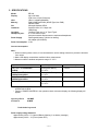
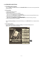
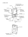

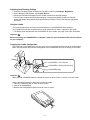
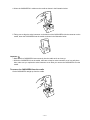

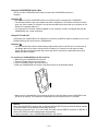


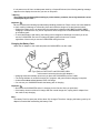
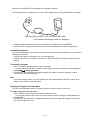
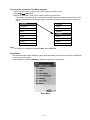
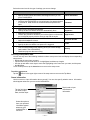
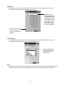
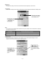
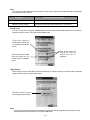
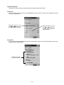
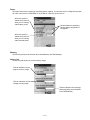
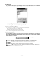
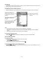
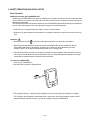
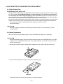
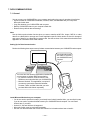
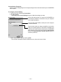
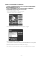

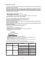
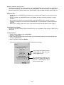
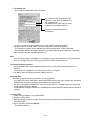
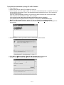
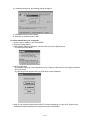
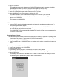
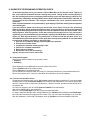

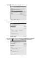
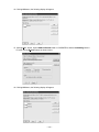

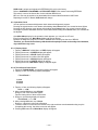

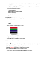
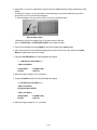
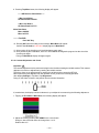
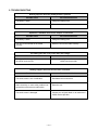
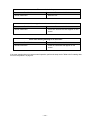
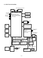
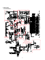

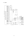
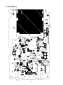
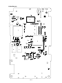

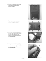
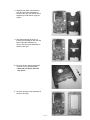
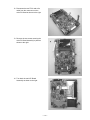

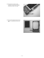
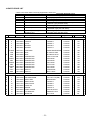
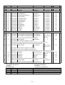
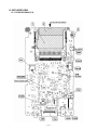
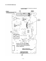
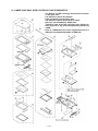
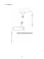

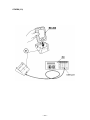

![Administrations communales [2 Mo] - Chêne](http://vs1.manualzilla.com/store/data/006515366_1-e981dd2a7716fcda94c2cbcedf41fd45-150x150.png)