1
USER'S MANUAL
* This User's Manual is intended for both PNC-1850 and PNC-1200.
For the USA
FEDERAL COMMUNICATIONS COMMISSION
RADIO FREQUENCY INTERFERENCE
STATEMENT
This equipment has been tested and found to comply with the
limits for a Class B digital device, pursuant to Part 15 of the
FCC Rules.
These limits are designed to provide reasonable protection
against harmful interference in a residential installation.
This equipment generates, uses, and can radiate radio
frequency energy and, if not installed and used in accordance
with the instructions, may cause harmful interference to radio
communications.
However, there is no guarantee that interference will not
occur in a particular installation.
If this equipment does cause harmful interference to radio or
television reception, which can be determined by turning the
equipment off and on, the user is encouraged to try to correct
the interference by one or more of the following measures:
- Reorient or relocate the receiving antenna.
- Increase the separation between the equipment and
receiver.
- Connect the equipment into an outlet on a circuit different
from that to which the receiver is connected.
- Consult the dealer or an experienced radio/TV technician
for help.
Unauthorized changes or modification to this system can void
the users authority to operate this equipment.
The I/O cables between this equipment and the computing
device must be shielded.
Grounding Instructions
Do not modify the plug provided - if it will not fit the outlet,
have the proper outlet installed by a qualified electrician.
Check with qualified electrician or service personnel if the
grounding instructions are not completely understood, or if in
doubt as to whether the tool is properly grounded.
Use only 3-wire extension cords that have 3-prong
grounding plugs and 3-pole receptacles that accept the tool’s
plug.
Repair or replace damaged or worn out cord immediately.
Operating Instructions
KEEP WORK AREA CLEAN. Cluttered areas and benches
invites accidents.
DON’T USE IN DANGEROUS ENVIRONMENT. Don’t
use power tools in damp or wet locations, or expose them to
rain. Keep work area well lighted.
DISCONNECT TOOLS before servicing; when changing
accessories, such as blades, bits, cutters, and like.
REDUCE THE RISK OF UNINTENTIONAL STARTING.
Make sure the switch is in off position before plugging in.
USE RECOMMENDED ACCESSORIES. Consult the
owner’s manual for recommended accessories. The use of
improper accessories may cause risk of injury to persons.
NEVER LEAVE TOOL RUNNING UNATTENDED.
TURN POWER OFF. Don’t leave tool until it comes to a
complete stop.
For Canada
CLASS B
NOTICE
NOTICE
This digital apparatus does not exceed the Class B limits for
radio noise emissions set out in the Radio Interference
Regulations of the Canadian Department of Communications.
CLASSE B
AVIS
Cet appareil numérique ne dépasse pas les limites de la
classe B au niveau des émissions de bruits radio électriques fixés dans le Réglement des signaux parasites
par le ministère canadien des Communications.
注意
KEEP HANDS AWAY WHEN CUTTING TOOL IS IN MOTION.
` VOUS METTEZ LES MAINS LORSQUE
REGARDEZ BIEN OU
L' OUTIL DE DECOUPE FONCTIONNE.
CAUTION
1) Unauthorized copying or transferral, in whole or in part, of this manual is prohibited.
2) The contents of this operation manual and the specifications of this product are subject to change without notice.
3) The operation manual and the product have been prepared and tested as much as possible. If you find any misprint or error, please
inform us.
4) We cannot in any way assume any responsibility whatsoever with regard to whatever consequences that may happen subsequent
to the making of changes or alterations to this product. We also cannot in any way assume responsibility for whatever may result
when this product is operated, or with regard to whatever results from making use of any explanatory documentation.
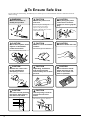
To Ensure Safe Use
If you find some abnormality, immediately turn off the power switch and check the user's manual to find out
what is wrong.
WARNING
Never disassemble or
modify this product.
CAUTION
Handle the power cord
with care.
Do not step on or damage the
power cord, or allow heavy
objects to be placed atop it.
Failure to heed this may result in
electrocution or fire.
CAUTION
Do not allow liquids, metal
objects or flammables
inside the machine.
CAUTION
Install in a level and stable
location.
CAUTION
When pulling the power
cord from an electrical
socket, be sure to grip the
plug.
CAUTION
Handle the blade with care.
The unit may tip over otherwise.
Fire or breakdown may result.
CAUTION
Release the caster locks
for the stand before
attempting to move.
CAUTION
Unpacking, installation,
and moving must be
carried out by two or more
persons.
FREE
LOCK
CAUTION
Use care to avoid pinching
the fingers when placing
the unit on the stand.
CAUTION
Use the joining screws to
secure the unit to the
stand.
The unit may tip over otherwise.
ii
CAUTION
Do not allow the hands
within the space to the
front or rear of the unit
while in operation.
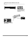
About the Labels Affixed to the Unit
These labels are affixed to the body of this product. The following figure describes the location and content of
these messages.
Be sure to press 'PAUSE' key
whenever you open the cover
when cutting is in progress.
Otherwise, you would lose the
ongoing data.
Rating plate
Do not allow the hands within the
space to the front or rear of the unit
while in operation.
iii
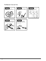
To Ensure Correct Use
NOTICE
NOTICE
This product is a precision
instrument and must be handled
with care.
NOTICE
NOTICE
When the unit is not in use for an
extended period, detach the power
supply plug from the AC outlet.
3
2
iv
Do not install in an area subject to
dust or high humidity or with poor
ventilation.
1
Arrange the power cord and
interface connection cable to
prevent tripping when moving
around the unit.
NOTICE
Do not connect to an AC outlet
that supplies other than the
specified voltage.
Thanks and Best Wishes
Thank you very much for purchasing the CAMM-1 PNC-1850/1200.
Since we wish you many years of productive use of your PNC-1850/1200, we ask you to read this manual and make yourself
familiar with the PNC-1850/1200 operational procedures and requirements before running it.
If something seems abnormal, turn OFF the power and reference this manual for answers, tips and procedures to solving the
problem.
Contents
Part 1
1-1
1-2
1-3
1-4
1-5
PRECAUTION ................................................................................................................................................... 3
CHECKING ACCESSORIES ............................................................................................................................. 3
PART NAMES AND FUNCTIONS ..................................................................................................................... 4
1-3-1 Front View .............................................................................................................................................. 4
1-3-2 Rear View ............................................................................................................................................... 4
1-3-3 Operation Panel ..................................................................................................................................... 5
BASIC OPERATION .......................................................................................................................................... 5
1-4-1 Setting Up and Connection .................................................................................................................... 5
1-4-2 Installing the Cutter ................................................................................................................................ 6
1-4-3 Loading the Sheet .................................................................................................................................. 8
When Using Rolled Sheet ...................................................................................................................... 9
When Using a Flat Sheet (Standard-size Sheet, Cut Sheet, Etc.) ....................................................... 13
1-4-4 Selecting the Interface .......................................................................................................................... 14
1-4-5 Cutting Test - Setting Cutting Speed, Blade Force, and Blade Compensation .................................... 15
1-4-6 Downloading Cutting Data .................................................................................................................... 16
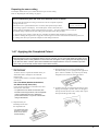
1-4-7 Applying the Completed Cutout ............................................................................................................ 17
1-4-8 When Completed Cutting ..................................................................................................................... 18
CARE AND MAINTENANCE ........................................................................................................................... 18
1
Part 2
2-1
2-2
2-3
2-4
ABOUT THE CUTTING AREA ........................................................................................................................ 19
ABOUT THE BLADE ....................................................................................................................................... 19
DISPLAY MENUS FLOWCHART .................................................................................................................... 20
EXPLANATION OF DISPLAY MENU .............................................................................................................. 22
• Determining the type of sheet loaded
[SELECT SHEET] .................................................. 22
• Setting cutting conditions
[1—8] Selecting and storing cutting parameters .... 22
[** cm/s] Setting cutting speed ............................... 23
[*.*** mm] Setting blade compensation .................. 24
[** gf] Setting blade force ....................................... 24
[SMOOTHING] Cutting smooth curves .................. 24
[SHEET WEIGHT] Cutting thicker sheets .............. 25
[UP SPEED] Setting tool movement speed
during tool-up ... 25
• Setting the origin point
[ORIGIN SET] ........................................................ 25
• Rotating the origin point
[AXIS ROTATION] ................................................. 26
• Feed the loaded sheet
[AREA] .................................................................... 26
[AREA UNIT] .......................................................... 26
[PREFEED] ............................................................ 27
• Correct for the cutting distance error based on actual measurement
[CALIB] ................................................................... 27
• Repeating the same cutting - Deletes any data in the replot buffer
[REPLOT] ............................................................... 27
2-5
2-6
2-7
2-8
• Selecting the instruction set
[COMMAND MODE] .............................................. 28
• Selecting the connection interface
[INTERFACE] ......................................................... 28
• Setting the protocol for a serial connection
[STOP BIT] Stop bit ............................................... 28
[DATA BIT] Data bit ............................................... 29
[PARITY MODE] Parity check ................................ 29
[BAUD RATE] Baud rate ....................................... 29
[HANDSHAKE] Handshake ................................... 29
• Giving priority to settings from the computer
[TOOL-CHG COMMAND]
Enabling pen change commands ................. 30
[VS COMMAND] VS command (Velocity Select) ..... 30
[FS COMMAND] FS command (Force Select) ...... 30
• Other setting
[ENGLISH/JAPANESE/GERMAN/FRENCH/SPANISH/ITALIAN]
Changing the language used for display ............. 31
[DISPLAY UNIT] Setting the coordinate unit
used for display ...... 31
[DEMO CUTTING MODE] Performing demo cutting ... 31
[UP/DOWN MOVE] Moving the blade .................. 31
PLOTTING ON PAPER MEDIA ....................................................................................................................... 32
WHAT TO DO IF..... ......................................................................................................................................... 34
2-6-1 What to do if... ...................................................................................................................................... 34
2-6-2 Error messages .................................................................................................................................... 37
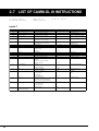
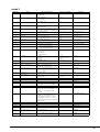
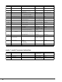
LIST OF CAMM-GL III INSTRUCTIONS ......................................................................................................... 38
DEVICE CONTROL INSTRUCTIONS ............................................................................................................. 41
Appendices
Appendix 1 CHARACTER SETS ............................................................................................................................. 43
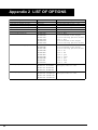
Appendix 2 LIST OF OPTIONS ............................................................................................................................... 44
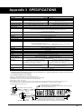
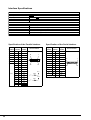
Appendix 3 SPECIFICATIONS ............................................................................................................................... 45
Copyright © 1994 ROLAND DG CORPORATION
2
Part 1
1-1 PRECAUTION
• Always be careful whenever the unit is in operation, so as not to risk getting fingers or hair caught in its mechanisms.
• If you are using a stand, take care not to make the PNC-1850/1200 tip over. When moving the PNC-1850/1200
always unlock the stand casters and use two or more people to complete the job. Single-handedly attempting to
use excessive force to move the PNC-1850/1200 may cause the unit to tip over, which is dangerous.
• Ensure that the power supply voltage in within ±10% of the machine's rated voltage.
• Never take apart, or alter the construction of this device.
• Never allow any liquids, metallic objects, or flammable material to get inside the unit.
• Handle the power cord carefully to prevent damage. Never step on or place heavy objects on the cord.
• When pulling the power cord from an electrical socket, be sure to grip the plug to prevent damage to the cord or
cause electrical shorts.
• When the machine is not in use for an extended period, remove the power supply plug from the AC outlet.
• Do not subject the machine to bumps, or other severe shocks.
• Never move the tool carriage by hand. Damage and performance inaccuracy may result.
• When the unit is not in use, keep the pinch rollers raised. The pinch rollers may be deformed if left engaged.
1-2 CHECKING ACCESSORIES
Check the following to make sure that you received all the items that were shipped along with the unit.
Power Cord: 1
Separate Cutter: 1
Blade Holder: 1
Blade for Sheet
(Cemented Carbide blade): 1
Test-use Sheet: 1
Test use Water based Test-use High-quality
Tweezers
(for handling sheet): 1 Fiber tipped Pen: 1
Paper: 1
Test-use Application
Tape: 1
User’s Manual: 1
Sheet Base: 1
* PNC-1200 only
3
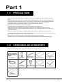
1-3 PART NAMES AND FUNCTIONS
1-3-1 Front View
* In the figures shown, the PNC-1850 is installed on the PNS-185 special stand.
Some details of the PNC-1200 differ from the figure.
Front Cover
This safety features prevents anything from coming into contact with the moving
parts during operation. Operation automatically stops when this cover is opened.
Movable Pinch Roller (Left)
This holds the media against the grit roller during cutting. It can be moved
from side to side, and should be aligned with the left edge of the sheet.
Movable Pinch Roller (Right)
This holds the media against the
grit roller during cutting. It can
be moved from side to side, and
should be aligned with the right
edge of the sheet.
Tool Carriage
The tool carriage is where the cutter
(or pen) is mounted. The tool carriage
performs the cutting by moving the
tool left/right or up/down.
Operation Panel
Grit Roller
Grasps and moves the sheet (or
paper) during cutting (or plotting).
Cutter Protector
Platen
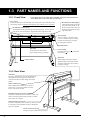
1-3-2 Rear View
Guard Bar
This safety-enhancing bar prevents the hands from
entering the area of moving parts from the space
on the back of the unit while cutting with a sheet
loaded.
Sheet Loading Lever
When loading media, lift this lever to lower to
pinch rollers. To removing media, lower this
lever to raise the pinch roller.
Parallel (Centronics) Connector
In a parallel configuration, this connector is where you
need to connect the parallel cable in order to communicate with your computer.
Serial (RS-232C) Connector
In a serial configuration, this connector is where you need
to connect the serial cable that is used to communicate
with your computer.
Power Connector [AC IN]
This jack accepts a standard AC power cord.
4
Power Switch
ON when switched to [
switched to [
].
], OFF when
Guide line
When loading a flat sheet, align the
right-hand edge of the sheet with this
guide line and load the sheet so that it
is perfectly straight.
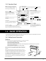
1-3-3 Operation Panel
Blinking Cursor
Used to select the desired item from the menu. The
key moves it
to the right, the
key moves it to the left, the
key moves it up,
the
key moves it down.
Display
Provides menu display, configuration
preferences, coordinates, as well as
error messages for troubleshooting.
MENU Key MENU
Employed to select among the
available menus, or to cancel the
making of a setting at a particular
menu.
1 Cut
0.250mm
50cm/s
30gf
Power LED
This lights up when the power is
switched on.
PAUSE LED
This lights up when the PAUSE key is
pressed to pause the PNC-1850/1200.
PAUSE Key PAUSE
When pressed once, this temporarily halts cutting in
progress. Pressing this key again releases the paused state.
ENTER Key ENTER
Press to enter into a subroutine of the
item selected using the cursor keys or
to confirm (save) the value set in
configuration.
Cursor Keys
Used to move the blinking cursor. The
and
keys are also used to
move the sheet, and the
and
keys are used to move the tool
carriage.
TEST Key TEST
Pressed to execute a cutting test (Use
to confirm material specifications as
well as cutting speed, blade force, and
blade compensation).
1-4 BASIC OPERATION
* In this manual, the sections that explain both the PNC-1850 and the PNC-1200 shown only illustrations of the PNC1850. Some details of the PNC-1200 differ from the figure.
1-4-1 Setting Up and Connection
Setting up
Never install this unit in any of the following situations, as it could result in damage:
Places where the installation surface is unstable or not level.
Places with excessive electrical noise.
Places with excessive humidity or dust.
Places with poor ventilation, because the PNC-1850/1200 generates considerable heat during operation.
Places with excessive vibration.
Places exposed to strong illumination or direct sunlight.
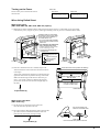
For an explanation of how to assemble the unit and the stand (PNS-185/
PNS-121), refer to the “ASSEMBLY INSTRUCTIONS” included with
the stand.
When arranging setup space for the PNC-1850, make sure you have a
space that is at least 1,200 mm (47-1/4") high, 1,600 mm (63") wide, and
750 mm (29-1/2") in depth. For the PNC-1200, a space that is at least
1,150 mm (45-5/16") high, 900 mm (35-7/16") wide, and 750 mm (29-1/
2") in depth is needed to install the unit on the stand.
Since the sheet moves during cutting, make sure the unit is placed on a
stable, sturdy surface. Also make sure the nothing will interfere or block
the movement of the media in any closer than 600 mm (23-5/8") to the
front or behind the unit.
600 mm
(23-5/8")
600 mm
(23-5/8")
5
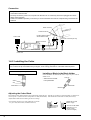
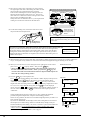
Connection
• Always make sure that the power is off on both the computer and the PNC-1850/1200 whenever any cables are
connected or disconnected.
• Securely connect the power cord, computer I/O cable and so on so that they will not be unplugged and cause
failure during operation.
• Cables are available separately. One which you are sure matches the model of computer being used should be
selected.
Serial connector
Parallel connector
Parallel interface cable or
Serial interface cable
Power outlet
Power connector [AC IN]
Parallel connector
Serial connector
Power cord
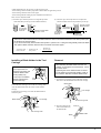
1-4-2 Installing the Cutter
• Always make sure the power switch is OFF before installing (or replacing) the cutter.
• Do not touch the tip of the blade with your fingers, as the cutting performance of the blade will be impaired.
Blade Holder (XD-CH2) Part Names
Push-pin
Scale
Installing a Blade in the Blade Holder
Insert a blade into the blade holder until it snaps into place with an
audible click.
Push-pin
* Take care not to break
or chip the blade.
Cap
Cutter blade
Blade holder
Blade
Adjusting the Cutter Blade
The amount of cutter blade extension can be adjusted by rotating the cap. Turn the cap clockwise to retract the blade or counterclockwise to expose it. (Each scale line corresponds to 0.1 mm (about 0.004"). One full turn moves the blade 0.5 mm (about 0.02").)
Adjust blade holder before mounting on the tool carriage.
• If an ordinary sheet is to be used, tighten the cap all the
way (2.5 mm (about 0.098") of blade extension).
Tighten the cap until
there is no gap
Turn the cap
as shown by
the arrow
6
Amount of cutter blade
extension: 2.5 mm
(about 0.098")
(maximum length)
• Blade adjustment may be necessary in the following cases:
- When cutting a sheet with base paper that is thinner than it's application portion.
- When cutting a material with no base paper
- When cutting without making any fine adjustment of blade force
Here’s how to adjust the blade.
(1) Turn the cap as shown by the arrow to align the tip of the
blade with the tip of the cap (0 mm of blade extension).
(2) Turn the cap as shown by the arrow to adjust the
amount of blade extension beyond the tip of the cap.
Amount of cutter
blade extension
Gap
Turn the cap
as shown by
the arrow
Thickness of the
sheet portion
Amount of cutter blade
extension: 0 mm
Turn the cap
as shown by
the arrow
Thickness of
the base paper
• Take care to ensure that the amount of blade extension does not exceed the thickness of the sheet portion plus
the thickness of the base paper.
• If you don’t know exactly how thick the sheet portion is, perform out a cutting test and gradually extend the blade.
The optimum blade extension leaves a faint score mark on the base paper.
Amount of cutter
Thickness of the
blade extension = sheet portion
+
Thickness of
the base paper
2
Installing a Blade Holder in the Tool
Carriage
As shown in the figure at
right, support the tool
setscrew from below and
install the blade holder.
Cutting quality may
become poor if installed
without supporting the
screw in this way.
Removal
After detaching the blade holder from the tool
carriage, do not tighten the tool setscrew. Leave
this screw loose.
Tightening the screw makes the hole for inserting the holder to progressively smaller, which in
turn makes it difficult to install the blade holder.
Tool securing
screw
1) Loosen the tool securing screw on the tool carriage,
then remove the blade holder from the tool carriage.
Blade holder
Loosen the tool securing screw on the tool carriage, then
insert the blade holder until the collar is flush with the
carriage.
Tighten the tool securing screw until the blade holder is
secured in place.
Tool carriage
Loosen
Blade holder
Tool carriage
Loosen
Tighten
Tool securing screw
2) Press the push-pin and
remove the blade from
the blade holder.
Push-pin
Tool securing screw
Blade
Blade holder
7
1-4-3 Loading the Sheet
You can load sheet measuring between 50 mm (1-15/16") and 1220 mm (48") in width (horizontal dimension) on the PNC-1850,
or sheet measuring between 50 mm (1-15/16") and 762 mm (30") in width (horizontal dimension) on the PNC-1200. However, a
sheet with a width of 50 mm (1-15/16") to 762 mm (30") can be loaded only if it is a flat sheet or a rolled sheet with a sheet base.
When using a stand (PNS-121), a rolled sheet with a width in the range of 50 mm (1-15/16") to 610 mm (24") can be loaded.
There is no particular restriction on sheet length (vertical dimension). This means that you can use either flat sheets such as
standard-size sheets (ANSI, ISO, etc.) and cut sheets, or roll sheets.
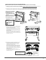
The grit rollers on the PNC-1850 are divided into three areas that can secure the sheet with the pinch rollers. Also, The grit
rollers on the PNC-1200 are divided into two separate areas. The range of movement is determined by the movable pinch rollers
on the left and right. Experiment with the range of the left and right movable pinch rollers to determine usable area.
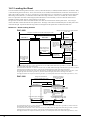
Reference — Sheet Loading Position
PNC-1850
Range of movement for the left movable pinch roller
Range of movement for the right movable
pinch roller
* Do not set the pinch roller here.
Grit roller 1
Grit roller 3
Grit roller 2
Move the left
pinch roller to
align it with the
left edge of the
sheet
Move the left pinch
roller to align it with
the left edge of the
sheet
Move the right pinch
roller to align it with
the right edge of the sheet
Sheets between
50 mm (1-15/16") and
280 mm (11") in width
Move the right pinch
roller to align it with
the right edge of the sheet
Sheets between 280 mm
(11") and 760 mm
(29-15/16") in width
Move the left pinch
roller to align it with
the left edge of the
sheet
Move the right pinch
roller to align it with
the right edge of the sheet
Sheets between 760 mm (29-15/16") and 1220 mm (48") in width
For a sheet between 50 mm (1-15/16") and 280 mm (11") in width, load the sheet above grit roller (3), and move the left and
right pinch rollers to the edges of the sheet.
For a sheet between 280 mm (11") and 760 mm (29-15/16") in width, load the left edge of the sheet above grit roller (2) and the
right edge of the sheet above grit roller (3), and move the left and right pinch rollers to the edges of the sheet.
For a sheet between 760 mm (29-15/16") and 1220 mm (48") in width, load the left edge of the sheet above grit roller (1) and
the right edge of the sheet above grit roller (3), and move the left and right pinch rollers to the edges of the sheet.
The right pinch roller can only be moved above grit roller (3). The left pinch roller can be moved above grit rollers (1) to (3).
PNC-1200
Range of movement
for the right movable
pinch roller
Range of movement for
the left movable pinch roller
* Do not set the pinch roller here.
Grit roller 2
Grit roller 1
Move the left
pinch roller to
align it with the
left edge of the
sheet
Move the left pinch roller to align
it with the left edge of the sheet
Move the right pinch roller to align
it with the right edge of the sheet
Sheets between
50 mm (1-15/16") and
230 mm (9-1/16") in
width
Move the right pinch roller to align
it with the right edge of the sheet
Sheets between 230 mm
(9-1/16") and 762 mm
(30") in width
For a sheet between 50 mm (1-15/16") and 230 mm (9-1/16") in width, load the sheet above grit roller (2), and move the left
and right pinch rollers to the edges of the sheet.
For a sheet between 230 mm (9-1/16") and 762 mm (30") in width, load the left edge of the sheet above grit roller (1) and the
right edge of the sheet above grit roller (2), and move the left and right pinch rollers to the edges of the sheet.
The right pinch roller can only be moved above grit roller (2). The left pinch roller can be moved above grit rollers (1) to (2).
8
Turning on the Power
Power ON
PNC-1850
Switch on the power switch on the front of
the main unit.
PNC-1200
PNC-1850
Roland DG Corp.
PNC-1200
Roland DG Corp.
When Using Rolled Sheet
When using stand
(PNC-1850: PNS-185, PNC-1200: PNS-121 (option))
(1) Mount the two shafts included with the stand on the sheet hanger and place a rolled sheet on top of the shafts.
(The shafts (2 pieces), stoppers (2 pieces), and stopper retaining screws (2 pieces) are included with the stand.)
Install the shafts to match either
the remaining amount (roll width)
of the sheet, or the diameter of
the rolled sheet’s core.
* Do not use with shafts installed
at both of these positions at the
same time.
Shafts
If the diameter of the rolled sheet
core is 72 mm (2-7/8") or less
Install the shaft here if the amount
of sheet remaining is small.
* One shaft should always be
installed here.
Sheet hangers
Front
Pass the stoppers onto
the shaft.
Tighten the stopper
retaining screws
provisionally.
Stopper
Shafts
Place the rolled
sheet here.
Front
Rear
Rear
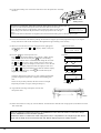
(2) Pull out as much from the roll as needed, and pass the
sheet from the back of the main unit to the front as shown
in the figure.
At this time, pull the sheet straight out, so that the left and
right sides of the sheet are parallel to the legs of the stand.
Make sure that the edge of the sheet lies above the grit
rollers. Also check to make sure that the left and right
pinch rollers can be moved to the left and right edges of
the sheet.
Pull out the sheet so that it is parallel to the stand legs
Pass between the pinch roller
and grit rollers
Pull out so that there is
no slack on either side.
Rolled Sheet
To procedure (3)
Rear
When using sheet base
(PNC-1200 only)
(1) Set the accessory sheet base in back of the unit.
Place the sheet base parallel to the unit.
Pull out the length to be
used from the rolled sheet
(2) Pass the end of the sheet between the pinch rollers and the
grit rollers so that it extends from the front of the unit.
Pull out some slack before you begin cutting.
To procedure (3)
Sheet base
Place the sheet base parallel to the unit.
9
(3) Move the two pinch rollers so that they are close to the left
and right edges of the sheet. When doing this, make sure that
the pinch rollers are positioned above the grit rollers.
Three stickers indicating the locations of the grit rollers are
affixed to the back surface of the front cover. You can use
these stickers to confirm the locations of the grit rollers when
the grit rollers are hidden by the sheet.
If the pinch rollers are difficult to move, try moving the sheet
loading lever on the back of the unit at the same time.
Make sure the left and right margins are the same size
Stickers showing the locations of the
grit rollers
Sheet
Move the pinch
rollers to inside
the edges of the
sheet
(4) Lift the sheet loading lever on the back of the unit to lower
the pinch roller and clamp the sheet.
Lift the sheet
loading levers
Before attempting to move the pinch roller, be
sure to lower the sheet loading lever to raise the
pinch roller.
Be sure to move the pinch rollers above the grit rollers when securing a sheet in the unit.
If you try to load a sheet with the pinch rollers at locations that are not above grit rollers,
Change Pinch
the message shown at right appears on the control panel. If this occurs, raise the sheet
Roller Position
loading levers and move the pinch rollers to the proper positions above the grit rollers.
Reposition the sheet to match this new alignment, then lower the sheet loading levers to
hold the sheet in place.
(5) When using the stand, secure the rolled sheet on the shafts by making sure that the two stoppers provisionally tightened in
step (1) are aligned exactly with the two sides of the rolled sheet, then tighten the stopper retaining screws securely.
(6) When you close the front cover, the message shown at right appears on the control
panel. Press
or
to display “ROLL,” then press the ENTER key.
* When performing cutting from the edge of the sheet closest to the front of
the PNC-1850/1200, select “EDGE.” When you press the ENTER key, the
unit scans the width of the loaded sheet and then aligns the front edge of the
sheet with the cutting starting position.
Close the front cover
(7) Press the MENU key on the top menu once.
Press
and align the blinking cursor with the “AREA” display in the top left of
the screen, then press ENTER. Move the blinking cursor to the numerals below
“LENGTH,” and change the value with the
and
cursor keys. Then set the
length of the sheet for cutting. (Ensure a small margin by setting a length that is about
0.1 m (3-15/16") longer than the cutting data.) Press ENTER to fix the displayed
values. Next press
or
to align the blinking cursor with the “MOVE” display at
the lower left of the screen. Press ENTER to feed a sheet of the length specified in
“LENGTH”.
Top menu
SELECT SHEET
ROLL EDGE PIECE
1 CUT
0.250mm
Press MENU once.
AREA
REPLOT
Use
Check alignment during the test to make sure it is free of offset and alignment
problems, diagonal feed problems, and pinch roller handling problems.
If there are any problems, the sheet was not loaded straight. Repeat the procedure over
again, starting from step (2).
If you turn on “PREFEED” on the display menu, when cutting data is received from
the computer (even without using “AREA” to feed the sheet), cutting will be performed automatically after feeding 1 m (39-3/8") of sheet. To prevent sheet offset and
alignment problems, we recommend making it a habit to feed the sheet with the
“AREA” function after loading.
For details on settings for “PREFEED”, refer to page 27.
10
50cm/s
30gf
AXIS
SUBMENU
or
to select.
Press ENTER.
AREA
MOVE
LENGTH
< 5.0m>
Use
or
to change the
value.
Use
to select “MOVE.”
Press ENTER.
Loading the sheet from the front of the PNC-1850/1200
(When sufficient space cannot be maintained at the back surface of the main body)
(1) With reference to the provided PNS-185/121 ASSEMBLY INSTRUCTIONS, mount the PNC-1850/1200 on the stand. One
sheet hanger should be at the front of the PNC-1850/1200 (the opposite position from the normal set position).
(2) Mount the two shafts included with the stand on the sheet hanger and place a rolled sheet on top of the shafts.
(The shafts (2 pieces), stoppers (2 pieces), and stopper retaining screws (2 pieces) are included with the stand.)
Install the shafts to match either
the remaining amount (roll width)
of the sheet, or the diameter of
the rolled sheet’s core.
* Do not use with shafts installed
at both of these positions at the
same time.
Shafts
If the diameter of the rolled
sheet core is 72 mm (2-7/8") or less
Install the shaft here if the amount
of sheet remaining is small.
Shafts
* One shaft should always be
installed here.
Pass the stoppers onto
the shaft.
Tighten the stopper
retaining screws
provisionally.
Stopper
Place the rolled
sheet here.
Sheet hangers
Rear
Rear
Front
Front
(3) Pull out as much from the roll as needed, and pass
the sheet from the front of the PNC-1850/1200 to
the back as shown in the figure.
At this time, pull the sheet straight out, so that the
left and right sides of the sheet are parallel to the
legs of the stand.
Make sure that the edge of the sheet lies above the
grit rollers. Also check to make sure that the left
and right pinch rollers can be moved to the left and
right edges of the sheet.
Pull out the sheet so that it is parallel to the stand legs
Pass between the pinch roller
and grit rollers
Pull out so that there is
no slack on either side.
Rolled Sheet
Front
(4) Move the two pinch rollers so that they are close
to the left and right edges of the sheet. When
doing this, make sure that the pinch rollers are
positioned above the grit rollers.
Three stickers indicating the locations of the grit
rollers are affixed to the back surface of the front
cover. You can use these stickers to confirm the
locations of the grit rollers when the grit rollers are
hidden by the sheet.
If the pinch rollers are difficult to move, try
moving the sheet loading lever on the back of the
unit at the same time.
Before attempting to move the
pinch roller, be sure to lower
the sheet loading lever.
Make sure the left and right margins are the same size
Stickers showing the locations of the
grit rollers
Sheet
Move the pinch
rollers to inside
the edges of the
sheet
11
(5) Lift the sheet loading lever on the back of the unit to lower the pinch roller and clamp
the sheet.
Lift the sheet
loading levers
Be sure to move the pinch rollers above the grit rollers when securing a sheet in the unit.
If you try to load a sheet with the pinch rollers at locations that are not above grit
Change Pinch
rollers, the message shown at right appears on the control panel. If this occurs, raise the
Roller Position
sheet loading levers and move the pinch rollers to the proper positions above the grit
rollers.
Reposition the sheet to match this new alignment, then lower the sheet loading levers to hold the sheet in place.
(6) Secure the rolled sheet on the shafts by making sure that the two stoppers provisionally tightened in step (2) are aligned
exactly with the two sides of the rolled sheet, then tighten the stopper retaining screws securely.
(7) When you close the front cover, the message shown at right appears
on the control panel. Press
or
to display “ROLL,” then press
the ENTER key.
Close the front cover
(8) Press the MENU key on the top menu once.
Press
and align the blinking cursor with the “AREA” display
in the top left of the screen, then press ENTER. Move the blinking
cursor to the numerals below “LENGTH,” and change the value with
the
and
cursor keys. Always set the value to a minus value
here. To feed a 3 m sheet, for example, set the value as -3.0 m. Be sure
to set the length slightly longer the actual cut length you want. Next
press
or
to align the blinking cursor with the “MOVE” display
at the lower left of the screen. Press ENTER to feed the sheet by the
length set in “ LENGTH. ”
Top menu
Check the output sheet to make sure it is free of offset and alignment
problems, diagonal feed problems, and pinch roller handling problems.
If there are any of these problems, the sheet was not set straight.
Repeat the procedure over again, starting from step (3).
SELECT SHEET
ROLL EDGE PIECE
1 CUT
0.250mm
Press
AREA
REPLOT
Use
Press
AREA
MOVE
Use
Use
Press
50cm/s
30gf
MENU
twice.
AXIS
SUBMENU
or
ENTER
to select.
.
LENGTH
<-3.0m>
or
to change the value.
to select “MOVE.”
ENTER .
(9) Align with the front edge of the platen, and cut with
the separate cutter.
Platen
(10) In the same manner as in step (8), execute “MOVE”. Feed the sheet to about the tool carriage position, toward the rear of the
PNC-1850/1200.
When the roll sheet is loaded from the front, the “PREFEED” function cannot be used to cut the sheet. Always
turn the “PREFEED” function off before operation.
Because the sheet is cut before the actual cutting data is sent, it is impossible to cut a length longer than the cut
length. Set the length to be fed toward the back with “MOVE” slightly longer than actually required.
12
When Using a Flat Sheet (Standard-size Sheet, Cut Sheet, Etc.)
(1) Pass the sheet between the pinch rollers and the grit rollers.
Pass the sheet
(2) Move the two movable pinch rollers so that they are close
to the left and right edges of the sheet. When doing this,
make sure that the pinch rollers are positioned above the
grit rollers.
Three stickers indicating the locations of the grit rollers
are affixed to the back surface of the front cover. You can
use these stickers to confirm the locations of the grit
rollers when the grit rollers are hidden by the sheet.
If the pinch rollers are difficult to move, try moving the
sheet loading lever on the back of the unit at the same
time.
Make sure the left and right margins are the same size
Stickers showing the locations of the
grit rollers
Sheet
Before attempting to move the pinch
roller, be sure to lower the sheet
loading lever to raise the pinch roller.
Move the pinch
rollers to inside
the edges of the
sheet
(3) Align the right edge of the sheet with the two guide lines located in
front of and behind the grit roller on the control panel side, and load
the sheet so that it is completely straight.
Lift the sheet loading lever on the back of the unit to lower the pinch
roller and clamp the sheet.
Guide line
Guide line
Lift the sheet
loading levers
• Be sure to move the pinch rollers to positions above the grit rollers when securing a sheet in place.
If you try to load a sheet with the pinch rollers at locations that are not above grit rollers,
Change Pinch
the message shown at right appears on the control panel. If this happens, raise the sheet
Roller Position
loading levers and move the pinch rollers to the proper positions above the grit rollers.
Reposition the sheet to match this new alignment, then lower the sheet loading levers to hold the sheet in place.
(4) When you close the front cover, the message shown at right appears on the control
panel. Press
or
to display “PIECE,” then press the ENTER key. The tool
carriage will move from side to side and the sheet will move forward and backward to
detect the size of the sheet. After this sensing is finished, the front edge of the sheet is
aligned with the cutting starting position.
(5) If sheet offset or alignment problems become apparent while the 1850/1200 is scanning
the piece in step (4) above, the sheet has not been loaded straight. Be sure to load the
sheet straight. Set the movable left and right pinch rollers inside the sheet edges.
Close the front cover
SELECT SHEET
ROLL EDGE PIECE
SELECT SHEET
ROLL EDGE PIECE
• If the sheet curls toward the sheet face (cut face), it will cause the sheet to slip when loaded onto the PNC1850/1200, and may adversely affect cutting. In this case pre-bend the sheet downward so that the sheet edge
is not caught the front cover and guard bar during operation.
• If the sheet strikes the shaft that is installed on the stand, then remove the shaft.
13
1-4-4 Selecting the Interface
Use the control panel to select the type of interface.
The selected interface type and communication parameters are stored in memory even after the power is switched off.
To change the interface type or the communication parameters, configurations must be re-entered.
(1) Set the output port for the computer (or software) to “Parallel” for a parallel
connection, or to “Serial” or “RS-232C” for a serial connection.
* The method used to make this setting varies according to the software
used. For details, refer to the manual for your software.
(2) Close the front cover.
(3), (4)
(3) Press the MENU key to display the menu shown at right.
(4) Use the
ENTER.
and
Use
keys to move the blinking cursor to “SUBMENU” and press
AXIS
SUBMENU
or
to select.
Press ENTER.
(5) Press the MENU key twice.
(6) Use the
AREA
REPLOT
and
(5)
keys to move the blinking cursor to “I/O” and press ENTER.
WEIGHT
SMOOTH
UPSPEED
CALIB
Press MENU twice.
* The PNC-1850/1200 is equipped with an auto-interface function, and so
when left set to “AUTO,” it will automatically determine whether a parallel or
serial connection is used. When a serial connection is used, however, it is
necessary to set the communication parameters to match those set for the
computer (and/or software).
(7) Pressing the
or
key will sequentially display “PARA,” “SERI,” and
“AUTO.”
If you are using a parallel connection, display “PARA” or “AUTO” and press
ENTER.
If a serial connection is used, display “SERI” or “AUTO” and press ENTER. Then
set the communication parameters for the PNC-1850/1200 to match those selected
for the computer (and/or software).
(8) When “SERIAL” or “AUTO” is selected, the menu at right then appears on the
display. Set each parameter to match the parameters used by the computer or
software. (Refer to “Setting the protocol for a Serial connection” on page 28.)
* If the communication parameters for the computer and the PNC-1850/1200
are not identical, the cutting data cannot be received correctly, which may
result in faulty operation.
(6)
COMMAND I/O
UNIT
END
Use
or
to select.
Press ENTER.
(7)
INTERFACE
PARA SERI<AUTO>
Use
or
(8)
PROTOCOL 1
STOP DATA PARITY
Press MENU.
PROTOCOL 2
BAUD HANDSHAKE
14
to select.
Press ENTER.
1-4-5 Cutting Test - Setting Cutting Speed, Blade Force, and Blade Compensation
For optimum performance, it is necessary to set cutting conditions that match the sheet, giving consideration to the sheet's
thickness and type of material. The PNC-1850/1200 has an internal "cutting test" to check the cutting conditions. This “cutting
test” allows you to determine settings for the cutting speed, blade force and the amount of offset.
Experiment with different settings for different types of material and adjust the configuration accordingly.
Procedure
1) Install a blade and load a sheet, then close the front cover (see from page 7 to 13).
Use the
,
,
and
keys to move the tool carriage to the position on the sheet for executing the cutting test.
• Note that an area of approximately 2 square centimeters (a little less than a square inch) is required to make a
test cutout (given that the tip of the cutter after it has moved is at the origin at lower-left).
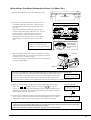
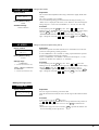
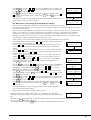
2) Press the TEST key for 0.5 seconds or more. Cutting test starts.
The resulting cutouts will then appear as illustrated.
Peel off first
Then, peel this off
3) Confirm the cutting speed and the blade force. Peel off the round section
(marked by
). Confirm that you can peel off the square section
(marked by
), but do not remove it. Also remove the square
section (marked by
). If the blade leaves a slight trail on the base
paper, you have achieved optimum cutting speed and blade force.
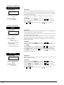
4) The remaining cross-shaped area is used to check whether
the offset value is set correctly. When the offset value has
been correctly set, the corners of the figure should appear
cleanly cut as shown in A of the figure below. If the offset
value is too small, the corners will appear slightly rounded
as illustrated by B; an offset value which is too large will
result in a cut figure similar to C.
A
Origin
(Position of the tool installed in step 1)
B
C
If the sheet was not cut correctly in steps 1) through 4) of the cutting test, change the cutting conditions.
Repeat the cutting test and adjustment until the optimal cutting speed, blade force, and blade compensation are found.
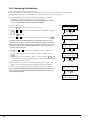
Adjusting cutting speed
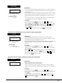
1) With a blade installed, a sheet loaded, and the front cover closed, check the display to make
sure that the message at right is shown. If you see a different menu, press the MENU key
until the message shown at right appears.
2) Press
or
1 CUT
0.250mm
50cm/s
30gf
to move the blinking cursor to value on the right side of the upper line of the display.
and
keys, alter the displayed value.
3) Using the
Select a speed from 1 cm/sec to 85 cm/sec (in increments 1 cm/sec). (When “HEAVY” is selected for “WEIGHT”: 1—50
cm/s.)
4) Press ENTER to confirm the selection.
If you haven't yet pressed ENTER, you can cancel the setting by pressing MENU instead.
The settings are now complete.
Adjusting blade force
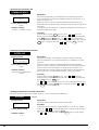
1) With a blade installed, a sheet loaded, and the front cover closed, check the display to make
sure that the message at right is shown. If you see a different menu, press the MENU key
until the message shown at right appears.
2) Press
or
1 CUT
0.250mm
50cm/s
30gf
to move the blinking cursor to value on the right side of the lower line of the display.
3) Using the
and
keys, alter the displayed value.
Select a speed from 30 gf to 500 gf (in increments 10 gf).
4) Press ENTER to confirm the selection.
If you haven't yet pressed ENTER, you can cancel the setting by pressing MENU instead.
The settings are now complete.
15
If the blade force is too weak, the sheet will not be cut completely. If the blade force is too strong, blade life will be shortened
Additionally, be aware other problems can be caused by high force settings:
The sheet is easily torn
The blade pierces the sheet
Cutting extends through the base paper, and normal advancing of the sheet becomes impossible
The unit suffers damage
Adjusting blade compensation
1) With a blade installed, a sheet loaded, and the front cover closed, check the display to
make sure that the message at right is shown. If you see a different menu, press the MENU
key until the message shown at right appears.
2) Press
or
1 CUT
0.250mm
50cm/s
30gf
to move the blinking cursor to value on the left side of the lower line of the display.
3) Using the
and
keys, alter the displayed value.
The range of values that can be set is from 0 to 1.000 mm (in increments 0.025 mm).
4) Press ENTER to confirm the selection.
If you haven't yet pressed ENTER, you can cancel the setting by pressing MENU instead.
The settings are now complete.
For more information on the blade compensation, see “*.*** mm Setting blade compensation” on page 24.
For Sheets with a Strong Adhesive Layer
If you are using a sheet with a strong adhesive layer, the adhesive layer may adhere to itself immediately when cut. This means that
even though the sheet has actually been cut, it may appear as if it has not been cut, and blade force may mistakenly be set too high.
If a cutting test shows that the sheet peels easily and the blade traces on the base paper are optimal, then the sheet is being cut.
Take care not to set the blade force excessively high.
1-4-6 Downloading Cutting Data
The unit will begin cutting when it receives cutting data sent from computer.
Software Setting
When cutting with commercially available application software, select PNC-1850/1200 as the setting for the output device. (If
the PNC-1850/1200 cannot be selected, choose any model in the PNC-1100, PNC-1000A, PNC-950 or PNC-900.)
Select either the parallel (Centronics) or serial (RS-232C) interface. Choose the one that the host computer and the PNC-1850/
1200 are connected by.
Pausing Cutting Operations
If you want to stop the PNC-1850/1200 momentarily while it is performing cutting, follow the procedure described below.
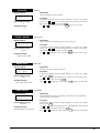
1) Press the PAUSE key. The PAUSE LED begins to flash and cutting pauses. When the LED
stops flashing and remains steadily lit, the message shown at right appears on the display.
CONT->PAUSE
STOP->ENTER
2)
Continue cutting (or plotting)
Press the PAUSE key. The PAUSE LED goes out and
cutting resumes.
Abort cutting
First of all, stop the flow of data being sent by the
computer.
Press the ENTER key. Cutting stops and you will see
the top menu.
Continuing Cutting
Cutting after changing the sheet
Again carry out the procedure described from “1-4-3 Loading the Sheet” on page 8 to “1-4-6 Downloading Cutting Data” on page 16.
* There is no need to perform the procedure described under “1-4-4 Selecting the Interface.” Also, if a sheet of the
same type is used, there is no need to perform a cutting test.
Continuing cutting on the same sheet
Refer to “Setting the origin point” on page 25 to set the origin for the area where cutting is to be carried out next.
If the sheet has not been fed to the cutting point when using roll sheets, use the “AREA” function on the display menu to feed the
sheet. Then send cutting data from the computer to the PNC-1850/1200.
16
Repeating the same cutting
The "Replot" feature allows you to create numerous copies of same cutting.
Refer to “Repeating the same cutting” on page 27.
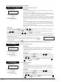
Do not inadvertently open the front cover while the unit is in motion.
Always make sure that the tool carriage or sheet has come to a complete stop before
Motor Error
opening the front cover.
Power ON Again
If the front cover is opened while the unit is in motion, then operation stops and an
error message appears on the display. Turn off the power switch to cancel the error.
Cutting cannot be resumed by simply closing the front cover again — the power switch must be turned off.
To perform cutting with data in use when cutting was interrupted, follow this procedure:
(1) Turn on the power switch to cancel the error, and make sure that the blade and sheet are loaded correctly.
(2) Refer to “Setting the Origin Point” on page 25 to set the origin at a location on the sheet which has not yet been cut.
(3) Cutting starts when you operate the computer to send cutting instructions.
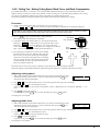
1-4-7 Applying the Completed Cutout
• Make sure beforehand that the surface where the work is to be stuck is clean and free of all dust or oily deposits.
• When applying the work to a transparent surface, such as a window, you can use a water-based pen (which can be
wiped off) after wards to mark guidelines on the reverse side of the glass, to aid in getting the work aligned properly.
• If you discover after it is stuck in place that air bubbles were trapped under the work, use a needle to puncture
them. Then you can smooth out the sheet so that it sticks securely.
1) Open the front cover.
For roll sheets
To make it easier to separate the finished cutout, you
should direct that a rectangle be cut around the
targeted work.
Use the separate cutter to cut off the completed portion
from the roll.
3) Stick application tape over the completed work.
Press down firmly or use a squeegee on the application
tape to remove air bubbles. If you do not press firmly
enough the cut area will not stick to the surface.
For a Flat Sheet (Standard-size Sheet,
Cut Sheet, Scrap, Piece, Etc.)
Lower the sheet loading levers and remove the sheet
from the PNC-1850/1200.
* If a portion that can still be cut remains, then
instead of removing the sheet, use the separate
cutter included with the unit to detach the
portion that has been cut, just as is done when
using a rolled sheet.
4) Carefully apply the work at the desired location, while
keeping it as straight as possible. Rub over the application tape to make sure the work is firmly stuck in place.
Then peel off the application tape.
2) Strip/Weed away all
unneeded portions from
the completed work.
*You should have weed
boarders or rectangles
drawn around work to
facilitate weeding.
Tweezers
17
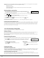
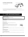
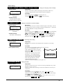
1-4-8 When Completed Cutting
Press down the sheet loading levers
1) When cutting is finished, press down the sheet loading
levers and remove the sheet.
Sheet
2) If a cutter was used, wipe the cutter with a soft cloth to remove any pieces of the sheet that may be adhering to it.
If a pen was used, remove the pen from the tool carriage and cap it securely.
3) Turn the power off. If you not intended to used the unit for an extended period of time, you should pull the plug for the power
cord out of the outlet.
1-5 CARE AND MAINTENANCE
Precautions in cleaning
• Always turn off the PNC-1850/1200 before cleaning it.
• Never lubricate the mechanisms.
• Use a small amount of water or alcohol for cleaning. Never use solvents such as benzene or thinner.
Cleaning the body
Use water or alcohol to clean, and wipe gently with a clean cloth. Wipe the operation panel and display gently with a clean, soft
cloth.
Cleaning the platen
If the platen is dirty clean with alcohol or water and wipe gently with a cloth.
Cleaning the grit rollers
With the sheet loading levers lowered and the pinch rollers raised, use a commercially
available brush to remove dust and other detritus. Brush horizontally while rotating the
grit rollers.
If dust builds up it may prevent the paper from being held securely, and degrade plot
precision.
Cleaning the pinch rollers
With the sheet loading levers lowered and the pinch rollers raised, use a cloth moistened with water or alcohol and wipe gently
to clean.
Cleaning the front cover
Use water or alcohol and clean with a soft cloth. If severe a neutral detergent may be used. Never use anything other than water,
alcohol or a neutral detergent.
Cleaning the blade holder cap
If sheet debris is adhering to the inner surface of the cap for the blade holder, loosen and remove the cap, then remove the sheet
debris.
18
Part 2
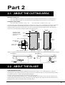
2-1 ABOUT THE CUTTING AREA
Maximum cutting area
PNC-1850: Width of 1195 mm (47") (horizontal direction), and length of 24,998 mm (984-1/8") (vertical direction)
PNC-1200: Width of 585 mm (23") (horizontal direction), and length of 24,998 mm (984-1/8") (vertical direction)
Acceptable sheet widths
PNC-1850: 50 mm—1220 mm (1-15/16"—48")
PNC-1200: 50 mm—610 mm (1-15/16"—24")
The cutting area along the horizontal plane (the direction in which the tool carriage moves) is determined by the position of the pinch
rollers. The workable area spans the length between the two rollers, minus a margin of about 1 mm (about 0.04") on both sides.
If the sheet length is greater than 1,600 mm (62-15/16") when a flat sheet (paper) has been loaded, the PNC-1850/1200 determines it to be a rolled sheet and sets the sheet length to 24,998 mm (984-1/8").
1195 mm
(47")
* The pairs of allows
indicate the positive
direction along the X
and Y axis.
585 mm
(23")
Sheet
Cutting area
Approx. 1 mm (about 0.04")
Movable pinch
roller (left)
24998 mm
(984-1/8")
10 mm
(3/8")
24998 mm
(984-1/8")
Approx. 15 mm
(about 9/16")
Cutting coordinates origin (0,0)
PNC-1850
Movable pinch
roller (right)
Movable pinch
PNC-1200 roller (right)
Whenever you employ the Rotate function (which allows you to rotate a character 90 degrees), the origin will be located at the sheet’s lower-right.
Y
X
Y
ABCD
Origin
X
[90° Rotation]
ABC
[0° Rotation]
Origin
2-2 ABOUT THE BLADE
If the blade becomes dull
When the blade starts to lose its sharpness, gradually increase the pen force (refer to “ ** gf Setting blade force” on page 24).
Increasing the pen force temporarily allows the cutter to compensate for a dull blade. However, increasing the blade force should
be a temporary measure. Consider replacing the blade immediately.
The life of a blade is determined mainly by the amount of cutting it performs.
The total cutting length actually obtained can vary considerably depending on the thickness, density, and type of adhesive layer
that the sheet has. By matching the force and blade settings to the type of material that is being used, the life of the blade can be
extended. Excessive forces will cause the blade to wear more quickly.
19
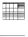
20
+ Power on
+ Power on
Openning message
PNC-1850
Roland DG Corp.
PNC-1200
Roland DG Corp.
ENGLISH JAPANESE
GERMAN FRENCH
ENGLISH/JAPANESE/
GERMAN/FRENCH/
SPANISH/ITALIAN
After loading a sheet,
close the front cover.
SELECT SHEET
ROLL EDGE PIECE
ROLL/EDGE/PIECE
or
to select.
Use
Press ENTER
WIDTH
14612
DEMO CUTTING
or
Use
to select.
Press ENTER to enable the setting.
SPANISH ITALIAN
MENU
LENGTH
-----MENU
Top menu
1— 8
1—85 (in increments of 1 cm/s)
1 CUT
0.250mm
0—1.000
(in increments of
0.025 mm)
50cm/s
30gf
Use
or
Use
and
* When [HEAVY] is selected for [WEIGHT] : 1—50
to select. (Align the blinking cursor at the item.)
to change the value. Press ENTER to enable the setting.
30—500
(in increments of 10 gf)
MENU
AREA
REPLOT
or
Use
to select.
(Align the blinking
cursor at the item.)
Press ENTER
AXIS
SUBMENU
Align the blinking cursor at the value, press
After making the setting for [LENGTH], press
AREA
AREA
MOVE
LENGTH
< 1.0m>
-24.9 m—+24.9 m (in increments of 0.1 m.) to feed the sheet at the set length.
* When [FEET] is selected for [AREAUNIT] : -82.17—+82.17 (in increments of 0.33 feet)
WEIGHT
Use
AXIS
or
to select. Press ENTER
AXIS ROTATION
<0deg> 90deg
or
Use
to select [START] or [CLEAR]
Press ENTER to enable the setting.
REPLOT
REPLOT
START
SHEET WEIGHT
<LIGHT> HEAVY
Use
and
to change the value.
Press ENTER to enable the setting.
LIGHT / HEAVY
UP SPEED
0deg / 90deg
MENU
or
to change the value, then press ENTER to confirm.
or
to move the blinking cursor to [MOVE] and press ENTER.
UP SPEED
<85cm/s>
Use
and
to change the value.
Press ENTER to enable the setting.
COMMAND / 1 cm/s — 85 cm/s (in increments of 1 cm/s.)
SMOOTH
CLEAR
SMOOTHING
OFF <ON>
Use
and
to change the value.
Press ENTER to enable the setting.
OFF/ON
Use
SUBMENU
WEIGHT
SMOOTH
UPSPEED
CALIB
CALIB
CALIB X CALIB Y
0.00%
0.00%
or
to select.
Use
and
to change the value.
Press ENTER to enable the setting.
-0.19% — 0.19% (in increments of 0.01%.)
or
Use
to select.
(Align the blinking cursor at the item.)
Press ENTER
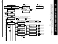
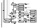
2-3 DISPLAY MENUS FLOWCHART
MENU
See “2-4 EXPLANATION OF DISPLAY MENUS” on page 22 for a detailed description of each setting.
Changing the value and pressing the ENTER key enables the setting. If you have changed a value but have not yet pressed ENTER, you can
abandon the change and return to the original value by pressing the MENU key.
To return to the menu selection screen from any of the menu value setting screens, press the MENU key.
Power on
MENU
UPDOWN TOOL-CHG
VS-CMND FS-CMND
UP DOWN
or
Use
to select.
(Align the blinking
cursor at the item.)
Press ENTER .
PEN-CHG
UP/DOWN->ENTER
->CURSOR
MOVE
Pressing ENTERmoves the blade up or down.
Pressing , , , or moves the cutter in
the +Y, -Y, -X, or +X directions, respectively.
TOOL-CHG COMMAND
<IGNORE> EFFECT
IGNORE / ACCEPT
VS-CMND
VS COMMAND
<IGNORE> EFFECT
or
Use
to select [IGNORE] or [EFFECT.]
Press ENTER to enable the setting.
IGNORE / ACCEPT
FS-CMND
MENU
FS COMMAND
<IGNORE> EFFECT
MENU
to select.
or
Use
(Align the blinking
cursor at the item.)
Press ENTER.
COMMAND I/O
UNIT
AREAUNIT
or
Use
to select.
Press ENTER to enable the setting.
COMMAND
MENU
or
Use
to select.
Press ENTER to enable the setting.
PREFEED END
PREFEED
to select [PREFEED].
or
Use
Press ENTER.
AUTO PREFEED
<OFF> ON
I/O
ORIGIN SET->ENTER
0
0
While PNC-1850 is
performing cutting
X
0
CONT->PAUSE
STOP->ENTER
Continue cutting. Press PAUSE .
Abort cutting: Press ENTER .
PROTOCOL 1
STOP DATA PARITY
UNIT
DISPLAY UNIT
<MACHINE> MILI
MACHINE / MILI (Milimeter)
or
Use
to select.
Press ENTER to enable the setting.
AREAUNIT
AREA MENU UNIT
<METRE> FEET
METRE / FEET
DATA BIT
7 <8>
PRITY
PARITY MODE
<NONE>ODD EVEN
or
Use
NONE / EVEN / ODD
to select.
or
Use
to select.
(Align the blinking
Press ENTER to enable the setting.
cursor at the item.)
Press ENTER
BAUD BAUD RATE
INTERFACE
PARA SERI<AUTO>
or
Use
to select.
Press ENTER to enable the setting.
Press PAUSE .
Y
0
DATA
7/8
PARA (Parallel) / SERI (Serial) / AUTO
OFF / ON
Use
, , , and
to move the tool
carreage and sheet to the position on the
sheet where the origin point is to be set.
Press ENTER to enable the setting.
COMMAND MODE
1 2 <AUTO>
STOP BIT
<1> 2
1/2
When set to [SERIAL]
or [AUTO] (communicati
on parameter setting)
1 (mode 1) / 2 (mode 2) / AUTO
MENU
Select [END.]
Press ENTER.
STOP
IGNORE / ACCEPT
19200 <9600>
MENU
MENU
PROTOCOL 2
BAUD HANDSHAKE
or
Use
to select.
(Align the blinking cursor at the item.)
Press ENTER .
BAUD RATE
4800 2400
2400 / 4800 / 9600 / 19200
HANDSHAKE
HANDSHAKE
<H-WIRE>XON/OFF
H-WIRE (Hardwire) / XON/OFF
21
2-4 EXPLANATION OF DISPLAY MENU
• Set values are stored in memory, and are not lost even if the power is switched off and back on again.
• Changing a value and pressing the ENTER key enables the setting. If you have changed a value but have not yet pressed
ENTER, you can abandon the change and return to the original value by pressing the MENU key.
• This explanation frequently refers to a “top menu.” This top menu is the screen shown below. This menu appears after you
load a sheet, close the front cover, and select the sheet type.
1 CUT
50cm/s
0.250mm
30gf
• Determining the type of sheet loaded
SELECT SHEET
Display readout
SELECT SHEET
ROLL EDGE PIECE
Available settings
ROLL, EDGE, and PIECE
Explanation
This determines the type of sheet that has been loaded. The PNC-1850/1200
automatically determines the width and length according to the type of sheet
loaded.
ROLL: Select this when a rolled sheet has been loaded on the PNC-1850/1200.
EDGE: This loads a rolled sheet and starts cutting from the front edge of the
sheet.
PIECE: Select this when a flat sheet (paper) has been loaded on the PNC-1850/
1200.
Procedure
This is displayed after loading a sheet and closing the front cover.
Refer to “1-4-3 Loading the Sheet” on page 8.
• Setting cutting conditions
Selecting and storing cutting parameters
1—8
Display readout
1 CUT
0.250mm
50cm/s
30gf
Factory default setting
1
Available settings
1, 2, 3, 4, 5, 6, 7 and 8
22
Explanation
It is possible to set the cutting parameters to match the tool and sheet, and store
them for later use. It is also possible to set plotting parameters to match pen and
paper conditions and store them.
Five items can be stored: “** cm/s” (cutting speed), “*.*** mm” (blade compensation), “**gf” (blade force), “UP SPEED” (tool movement speed during tool-up),
and “WEIGHT”. Eight patterns of these settings can be stored.
* When setting the cutting parameters set “*.*** mm” between 0.025 and
1.000 mm, and when setting pen plotting parameters set to 0.000 mm.
When the “*.*** mm” (blade compensation) value on the bottom line is 0.025 to
1.000 mm “CUT” will be displayed, and when set to 0.000 mm “PEN” will be
displayed. In other words, when the value is set to 0.000 mm, the plotter assumes
automatically that you are using a pen. In this case, substitute the work “cut” with
the word “plot” in this section. Refer to “2-5 PLOTTING ON PAPER MEDIA”
on page 32 for details on plotting on paper.
Procedure
This is set on the top menu.
or
keys to move the blinking cursor to the left of the top display
Use the
line (referred to below as the tool number). Use the
and
keys to display
the tool number (1 to 8) that you wish to set the cutting parameters to.
First, set the values for “** cm/s” (cutting speed), “*.*** mm” (blade compensation), and “** gf” (blade force) on the same screen. Use the
or
keys to
move the blinking cursor to the item to be changed, and use the
and
keys
to change the displayed values, and press ENTER to save them.
or
keys to move the blinking cursor to the
Press MENU once. Use the
“SUBMENU” item at the right of the bottom line, and press ENTER. Use the
or
keys to move the blinking cursor to “WEIGHT”, and press ENTER. Change
the value with the
or
keys and press ENTER to save the value.
Press MENU to return to the initial screen, and press the
or
keys to move
the blinking cursor to “UPSPEED”. Press ENTER. Use the
and
keys to
change the value, and press ENTER to save it.
The values set for each item are now stored to the tool number shown at the left of
the top line. To store other parameters, display another tool number and repeat the
process.
or
keys to move the blinking cursor to the tool
Before cutting use the
number on the top menu, and press the
and
keys to select the tool number
needed for the mounted current and sheet. When data is sent from the computer
cutting will be executed in accordance with those cutting parameters. Even if a
screen other than the top menu is displayed, cutting parameters will be those for
the tool number selected on the top menu.
When cutting is executed to a tool selection command (SP command) from the
computer, the PNC-1850/1200 tool number cutting parameters are set to match
the software (or driver). Turn on “TOOL-CHG” on the display menu. For
information on “TOOL-CHG”, refer to “TOOL-CHG COMMAND Enabling tool
change commands” on page 30.
** cm/s
Display readout
1 CUT
0.250mm
50cm/s
30gf
Factory default setting
50 cm/s
Settings range
1—85 cm/s (in increments of 1 cm/s)
When “ HEAVY” is selected
for “WEIGHT” :
1—50 cm/s (in increments of 1 cm/s)
Setting cutting speed
Explanation
This sets the speed on the tool movement during cutting (i.e., when the tool is
down). The setting must match the conditions of the loaded sheet and blade.
Perform a cutting test and make the appropriate settings.
If “VS COMMAND” is set to “EFFECT,” cutting is performed at the speed set
with the VS command send from the computer.
Procedure
This setting is made at the top menu.
Press
or
to move the blinking cursor to “ ** cm/s” on the right side of the
upper line of the display.
Use
and
to change the value. Display the value for the setting and press
ENTER to save it.
For more details, refer to “1-4-5 Cutting Test” on page 15.
23
*.*** mm
Display readout
1 CUT
0.250mm
50cm/s
30gf
Factory default setting
0.250 mm
Settings range
0 to 1.000 mm
(in increments of 0.025 mm)
Setting blade compensation
Explanation
Center axis
This sets the amount of offset from the center to the
cutting tip of the blade. When cutting two lines that form a
corner, this offset rounds the angle of intersection,
resulting in a rounded corner.
When blade compensation has been set, the PNC-1850/
1200 performs this compensation automatically.
Offset
The setting must match the conditions of the loaded sheet and blade. Perform a
cutting test and make the appropriate settings.
It is sufficient if the setting made here is within an adjustment range of ±0.05 mm
from the offset value for the cutter blade. (For example, if the cutter blade is
0.250 mm, the setting should be between 0.200 and 0.300.)
The offset for the cutter blade included with the unit is 0.250 mm.
* When a pen has been installed to perform plotting, there is no need to set blade
compensation, because the tip of the pen lies along the center axis. In this case,
the setting “0.000 mm” should be made.
Procedure
This setting is made at the top menu.
Press
or
to move the blinking cursor to “ *.*** mm” on the left side of
the lower line of the display.
Use
and
to change the value. Display the value for the setting and press
ENTER to save it.
For more details, refer to “1-4-5 Cutting Test” on page 15.
Setting blade force
** gf
Display readout
1 CUT
0.250mm
50cm/s
30gf
Factory default setting
30 gf
Settings range
30—500 gf
(in increments of 10 gf)
SMOOTHING
Display readout
SMOOTHING
OFF <ON>
Factory default setting
ON
Available settings
ON / OFF
24
Explanation
This sets the amount of pressure or force of the blade during cutting. The setting
must match the conditions of the loaded sheet and blade. Perform a cutting test
and make the appropriate settings.
Procedure
This setting is made at the top menu.
Press
or
to move the blinking cursor to “ *.*** mm” on the right side of
the lower line of the display.
Use
and
to change the value. Display the value for the setting and press
ENTER to save it.
For more details, refer to “1-4-5 Cutting Test” on page 15.
Cutting smooth curves
Explanation
If you want the curves of circles and arcs to be cut smoothly, set this to “ON.”
When on, however, small text or intricate designs may also be cut with rounded
corners. If this happens, change the setting to “OFF” and perform cutting again.
Procedure
At the top menu, press the MENU key once. Press
or
to move the
blinking cursor to “SUBMENU” on the right side of the lower line of the display,
and press ENTER. Next, use
or
to move the blinking cursor to
“SMOOTH” on the left side of the lower line of the display, and press ENTER
again. Change the value with
or
and press ENTER to save the new setting.
SHEET WEIGHT
Display readout
SHEET WEIGHT
<LIGHT> HEAVY
Factory default setting
LIGHT
Available settings
LIGHT / HEAVY
UP SPEED
Display readout
UP SPEED
<85cm/s>
Factory default setting
85 cm/s
Settings range
COMMAND /
1—85 cm/s (in increments of 1 cm/s)
When “ HEAVY” is selected
for “WEIGHT” :
1—50 cm/s (in increments of 1 cm/s)
Cutting thicker sheets
Explanation
This is used to make adjustment when using a sheet that is slightly thicker than
ordinary.
This value is normally set to “LIGHT”.
If an overload during cutting prevents the sheet from being cut cleanly, or if
“Motor Error” is displayed on the screen, set to “HEAVY.” This will change the
setting ranges for “**cm/s” and “UP SPEED” to 1—50 cm/s, in 1 cm/s steps.
Procedure
At the top menu, press the MENU key once. Press
or
to move the
blinking cursor to “SUBMENU” on the right side of the lower line of the display,
and press ENTER. Next, use
or
to move the blinking cursor to
“WEIGHT” on the left side of the upper line of the display, and press ENTER
again. Change the value with
or
and press ENTER to save the new setting.
Setting tool movement speed during tool-up
Explanation
This sets the speed of movement when the tool is raised and moves to the next
position for cutting during a cutting operation.
If “VS COMMAND” is set to “EFFECT,” cutting is performed at the speed set
with the VS command send from the computer.
If set to “COMMAND,” “UP SPEED” is the same as the setting for “** cm/s,”
regardless of whether set to “EFFECT” or “IGNORE.”
Procedure
or
to move the
At the top menu, press the MENU key once. Press
blinking cursor to “SUBMENU” on the right side of the lower line of the display,
and press ENTER. Next, use
or
to move the blinking cursor to
“UPSPEED” on the right side of the upper line of the display, and press ENTER
again. Change the value with
or
and press ENTER to save the setting.
• Setting the origin point
ORIGIN SET
Display readout
ORIGIN SET->ENTER
0
0
Explanation
Set a user origin at an arbitrary point on the sheet.
After the sheet has been loaded, be sure to set the origin to the bottom left of the
sheet.
Procedure
At the top menu, press the MENU key twice.
,
,
and
to move the tool carriage and sheet to the position on
Use
the sheet where the origin point is to be set. Press ENTER to enable the new
setting.
* Because the origin point is not sent unless ENTER is pressed, this function can
also be used simply for moving the tool.
25
• Rotating the origin point
AXIS ROTATION
Display readout
AXIS ROTATION
<0deg> 90deg
Factory default setting
0 deg
Available settings
0 deg / 90 deg
Explanation
This rotates the cutting coordinate origin by 90 degrees. This is normally set to
“0deg,” which means that the origin is at the bottom left of the sheet. Setting this
to “90deg” moves the origin to the bottom right of the sheet, thereby rotating the
cutting pattern by 90 degrees.
* Don’t forget that the coordinate axis changes when the origin is rotated.
Procedure
At the top menu, press the MENU key once. Press
or
to move the
blinking cursor to “ROTATE” on the right side of the upper line of the display,
and press ENTER.
and
to change the value and press ENTER to save the setting.
Use
• Feed the loaded sheet
AREA
Display readout
AREA
MOVE
LENGTH
< 1.6m>
Factory default setting
1.6 m
Settings range
-24.9—+24.9 m
(in increments of 0.1 m)
When “FEET” is selected
for “AREA UNIT” :
-82.17—+82.17 f (feet)
(in increments of 0.33 feet)
Explanation
Before performing cutting, feed the sheet to make sure that it has enough material
to complete the area test and the intended design.
Also, this checks whether enough sheet remains to cut the data when performing
continuous cutting on the same sheet.
For instance, suppose that the length of the design is one meter. This means that
there must be at least one meter of sheet remaining. You can use this menu to
feed the sheet and check whether there is enough sheet left, as well as check the
alignment of the media.
Procedure
At the top menu, press the MENU key once. Press
or
to move the
blinking cursor to “AREA” on the left side of the upper line of the display, then
press ENTER.
Move the blinking cursor to “LENGTH” and use
and
to change the value.
Set the length of sheet for checking (the approx. length of the intended design).
Press ENTER to enable. Next, press
to move the blinking cursor to “MOVE”
on the left side of the bottom line of the display. Press ENTER to feed the sheet by
the length set for “LENGTH.”
AREA UNIT
Display readout
AREA MENU UNIT
<METRE> FEET
Factory default setting
METRE
Available settings
METRE / FEET
26
Explanation
Sets the units used to specify length in display menu “AREA”. Units may be set to
either “METRE” or “FEET”.
Procedure
At the top menu, press the MENU key once. Press
or
to move the
blinking cursor to “SUBMENU” on the right side of the lower line of the display,
and press ENTER, then press MENU key twice. Use
or
to move the
blinking cursor to “AREAUNIT” on the right side of the lower line of the display,
and press ENTER again.
and
to change the value and press ENTER to save the setting.
Use
PREFEED
Display readout
AUTO PREFEED
<OFF> ON
Factory default setting
OFF
Available settings
ON / OFF
Explanation
Set to on for automatic sheet feed at cutting. If this is set to on, when cutting data
is sent from the computer, the plotter will automatically execute cutting after a 1
m (39-3/8") feed.
After the sheet is loaded be sure to feed the sheet by the length needed for cutting
with the “AREA” function. (Some data may cause feed over 1 m (39-3/8") , such
as when the next point of movement is located more than 1 m (39-3/8") to the
rear.)
* If the “AREA” function is used to feed the sheet in advance, the sheet will not
be automatically fed even when “PREFEED” is set to on.
Procedure
At the top menu, press the MENU key once. Press
or
to move the
blinking cursor to “SUBMENU” on the right side of the lower line of the display,
and press ENTER, then press MENU key three times. Use
or
to move the
blinking cursor to “PREFEED” on the left side of the upper line of the display,
and press ENTER again.
and
to change the value and press ENTER to save the setting.
Use
• Correct for the cutting distance error based on actual measurement
CALIB
Display readout
CALIB X
0.00%
CALIB Y
0.00%
Factory default setting
0.00%
Settings range
-0.19—0.19%
(in increments of 0.01%)
Explanation
This makes adjustment for distance over the X or Y axis. There may be a
discrepancy between size of the data sent from the computer and the size actually
cut, and this setting makes adjustment for such errors.
Before making this setting, first measure the results of cutting, compare them with
the data sent from the computer, and then calculate the amount of distance
adjustment.
Procedure
At the top menu, press the MENU key once. Press
or
to move the
blinking cursor to “SUBMENU” on the right side of the lower line of the display,
and press ENTER.
or
to move the blinking cursor to “CALIB” on the right side of
Next, use
the lower line of the display, and press ENTER again. Use
or
to align the
blinking cursor with “CALIB X” or “CALIB Y,” then press
or
to change
the value. Press ENTER to save the setting.
• Repeating the same cutting - Deletes any data in the replot buffer
REPLOT
Display readout
REPLOT
START
CLEAR
Explanation
REPLOT: Repeats the same cutting sequence.
CLEAR: Deletes any data in the replot buffer.
*Once you turn the power OFF, all data that until then was kept stored will be
lost. For this reason, the same cutting cannot be made when you turn power ON
again.
Procedure
At the top menu, press the MENU key once. Press
or
to move the
blinking cursor to “REPLOT” on the left side of the lower line of the display, and
press ENTER.
or
to “START” and press
To start replotting, move the blinking cursor
ENTER. To erase the data in the replot buffer, move the blinking cursor
or
to “CLEAR” and press ENTER.
27
• Selecting the instruction set
COMMAND MODE
Display readout
Explanation
This selection enables the type of instructions that are understood by the unit.
You can set the unit to accept either CAMM-GL III mode 1 instructions (“1”) or
mode 2 instructions (“2”).
When set to “AUTO,” the PNC-1850/1200 automatically detects the type of
instructions first received after turning on the power, and sets itself to accept those
instructions.
To change the type of instructions, first change the setting, then switch the power
to the unit off and back on again.
COMMAND MODE
1 2 <AUTO>
Factory default setting
AUTO
Available settings
1 (mode 1) / 2 (mode 2) / AUTO
Procedure
At the top menu, press the MENU key once. Press
or
to move the
blinking cursor to “SUBMENU” on the right side of the lower line of the display,
press ENTER, then press MENU twice. Use
or
to move the blinking
cursor to “COMMAND” on the left side of the upper line of the display, and press
or
and press ENTER to save the
ENTER again. Change the value with
setting.
• Selecting the connection interface
INTERFACE
Explanation
This selects the interface for connecting a computer to the PNC-1850/1200.
Set this to “PARALLEL” for a parallel connection or to “SERIAL” for a serial
connection.
When set to “AUTO,” the PNC-1850/1200 automatically detects whether a
parallel or serial type interface is used when data is first received after turning on
the power, and sets itself accordingly. To change the type of interface, first
switch off the power to the unit, change the cable connection, then turn the unit
back on again. See “1-4-4 Selecting the Interface” on page 14 for details.
Display readout
INTERFACE
PARA SERI<AUTO>
Factory default setting
AUTO
Available settings
PARA (Parallel) / SERI (Serial)
/ AUTO
Procedure
At the top menu, press the MENU key once. Press
or
to move the
blinking cursor to “SUBMENU” on the right side of the lower line of the display,
press ENTER, then press MENU twice.
Use
or
to move the blinking cursor to “I/O” on the right side of the upper
line of the display, and press ENTER again. Change the value with
or
and
press ENTER to save the setting.
• Setting the protocol for a serial connection
* The screen shown here appears when “SERI” (Serial) or “AUTO” is selected for “INTERFACE.”
STOP BIT
Display readout
STOP BIT
<1> 2
Factory default setting
1
Available settings
1/2
28
Stop bit
Explanation
This marker tells the system when a character data set end.
Procedure
At the screen following selection of either “SERIAL” or “AUTO” for “INTERFACE,” use
or
to move the blinking cursor to “STOP” on the left side of
the lower line of the display, then press ENTER.
or
to change the value, and press ENTER again to save the setting.
Use
DATA BIT
Display readout
DATA BIT
7 <8>
Factory default setting
8
Available settings
7/8
PARITY MODE
Display readout
PARITY MODE
<NONE>ODD EVEN
Factory default setting
NONE
Available settings
NONE / EVEN / ODD
BAUD RATE
Display readout
BAUD RATE
19200 <9600>
Factory default setting
9600
Available settings
2400 / 4800 / 9600 / 19200
HANDSHAKE
Display readout
HANDSHAKE
<H-WIRE>XON/OFF
Factory default setting
H-WIRE
Available settings
H-WIRE (Hardwire) / XON/OFF
Data bit
Explanation
The size (length) of one block of data.
Procedure
At the screen following selection of either “SERIAL” or “AUTO” for “INTERor
to move the blinking cursor to “DATA” in the center of
FACE,” use
the lower line of the display, then press ENTER.
Use
or
to change the value, and press ENTER again to save the setting.
Parity check
Explanation
Parity is used to check whether data was received correctly.
Procedure
At the screen following selection of either “SERIAL” or “AUTO” for “INTERFACE,” use
or
to move the blinking cursor to “PARITY” on the right
side of the lower line of the display, then press ENTER.
or
to change the value, and press ENTER again to save the setting.
Use
Baud rate
Explanation
Determines the speed of data transmission.
Procedure
At the screen following selection of either “SERIAL” or “AUTO” for “INTERFACE,” press MENU.
or
to move the blinking cursor to “BAUD” on the left side of the
Use
lower line of the display, then press ENTER.
Press
or
to change the value, and press ENTER again to save the setting.
Handshake
Explanation
Sets the handshake mode for when the PNC-1850/1200 is connected the host
computer via the serial interface.
Procedure
At the screen following selection of either “SERIAL” or “AUTO” for “INTERFACE,” press MENU.
or
to move the blinking cursor to “HANDSHAKE” on the right side
Use
of the lower line of the display, then press ENTER.
or
to change the value, and press ENTER again to save the setting.
Press
29
• Giving priority to settings from the computer
TOOL-CHG COMMAND
Enabling tool change commands
Display readout
Explanation
This sets the handling of tool select (SP instruction). When cutting is executed,
normally set this to “IGNORE”.
When a tool select command (SP command) is sent from the computer, it will be
ignored if this is set to “IGNORE”. If set to “EFFECT”, SP change commands will
be received. If tool changes are needed set this to “EFFECT”.
When plotting with pen and paper, set to “EFFECT” if pen change is needed (or if
data includes pen change commands). Select the top menu tool number (number at
left of top line on display) and software (or driver) pen number to match the pen to
be used.
For plot data without pen changes, or if pen change data is present but you will
ignore it, set “IGNORE”. In this case, before sending the data from the computer
select the tool number from the top menu with the correct plotting parameters (or
set a tool number if there isn’t one).
Refer to page 32 “2-5 PLOTTING ON PAPER MEDIA” for additional information
on plotting.
TOOL-CHG COMMAND
<IGNORE> EFFECT
Factory default setting
IGNORE
Available settings
IGNORE / EFFECT
Procedure
At the top menu, press the MENU key once. Press
or
to move the blinking cursor to “SUBMENU” on the right side
of the lower line of the display, press ENTER, then press MENU again.
or
to move the blinking cursor to “TOOL-CHG” on the right side of the upper line of the display, and press
Use
ENTER again. Change the value with
or
and press ENTER to save the new setting.
* See “2-5 PLOTTING ON PAPER MEDIA” on page 32 for a description of operation when a pen change command is received.
When “EFFECT” is selected and a tool select command is sent from the computer, the following message will be displayed,
and all operation will halt.
TOOL-CHG:TOOLNO2
When this message is displayed and the tool must be changed, open the front cover, and
insert the appropriate tool into the tool carriage and close the front cover. Press ENTER and
plotting will restart.
If tool change is not required, press ENTER when the message is displayed and plotting will restart.
If the tool select command from the computer specifies the tool number, select the tool number from the top menu.
VS COMMAND
Display readout
VS COMMAND
<IGNORE> EFFECT
Factory default setting
IGNORE
Available settings
IGNORE / EFFECT
FS COMMAND
Display readout
FS COMMAND
<IGNORE> EFFECT
Factory default setting
IGNORE
Available settings
IGNORE / EFFECT
30
VS command (Velocity Select)
Explanation
To perform cutting at the speed determined by a VS command (tool speed setting
command) sent from the computer, set this to “EFFECT.” When set to “IGNORE,” cutting is performed using the values for “ ** cm/s” and “UPSPEED”
set at the top menu.
Procedure
or
to move the
At the top menu, press the MENU key once. Press
blinking cursor to “SUBMENU” on the right side of the lower line of the display,
press ENTER, then press MENU again.
or
to move the blinking cursor to “VS-CMND” on the left side of the
Use
lower line of the display, and press ENTER again. Change the value with
or
and press ENTER to save the setting.
FS command (Force Select)
Explanation
To perform cutting at the tool force determined by an FS command (tool force
setting command) sent from the computer, set this to “EFFECT.” When set to
“IGNORE,” cutting is performed using the value for “** gf” set at the top menu.
Procedure
At the top menu, press the MENU key once. Press
or
to move the
blinking cursor to “SUBMENU” on the right side of the lower line of the display,
press ENTER, then press MENU again.
or
to move the blinking cursor to “FS-CMND” on the right side of
Use
the lower line of the display, and press ENTER again. Change the value with
or
and press ENTER to save the new setting.
• Other setting
ENGLISH JAPANESE GERMAN FRENCH SPANISH ITALIAN
Display readout
Changing the language used for display
Explanation
The PNC-1850/1200 is capable of displaying all its menus in either of six
languages, English, French, German, Spanish, Italian and Japanese.
ENGLISH JAPANESE
GERMAN
FRENCH
Procedure
While holding down the MENU key, turn the power on.
or
to select. Press ENTER to save the setting.
Using the
Factory default setting
ENGLISH
Available settings
ENGLISH, FRENCH, GERMAN,
SPANISH, ITALIAN and JAPANESE
DISPLAY UNIT
Setting the coordinate unit used for display
Display readout
Explanation
This sets the type of unit for coordinate values that appear on the display. Set this
to “MECHANICAL UNIT” for display in cutting coordinate units (1 = 0.025 mm),
or to “MILLIMETER” for display in millimeters.
DISPLAY UNIT
<MACHINE> MILI
Factory default setting
MACHINE
Procedure
At the top menu, press the MENU key once. Press
or
to move the blinking
cursor to “SUBMENU” on the right side of the lower line of the display, press
ENTER, then press MENU twice. Use
or
to move the blinking cursor to
“UNIT” on the left side of the lower line of the display, and press ENTER again.
Change the value with
or
and press ENTER to save the new setting.
Available settings
MACHINE / MILLIMETER
DEMO CUTTING MODE
Display readout
DEMO CUTTING
Factory default setting
—
UP/DOWN MOVE
Display readout
UP/DOWN->ENTER
->CURSOR
MOVE
Performing demo cutting
Explanation
This performs an operation check when the PNC-1850/1200 is not working
correctly.
Procedure
* A computer is not required in order to carry out the self-test.
Refer to “1-4-2 Installing the cutter” and
install a blade holder in the tool carriage.
on the panel while you
Hold down the
turn the power ON.
Load the sheet, following the procedure
described in “1-4-3 Loading the sheet.”
Close the front cover and use the display
menu to select the type of sheet loaded.
After sensing the sheet size, the PNC1850/1200 begins demo cutting.
Operation is normal if the figure shown at right is cut.
Moving the blade
Explanation
This moves the tool up or down. It also moves the tip of the blade in any of four
directions (-X, +X, -Y, or +Y).
With the tool down, the tool carriage can be moved with the four cursor keys to
cut the sheet.
Procedure
or
to move the
At the top menu, press the MENU key once. Press
blinking cursor to “SUBMENU” on the right side of the lower line of the display,
press ENTER, then press MENU again.
To move the tool up or down, press ENTER. To move in the -X, +X, -Y, or +Y
direction, press
,
,
, or
, respectively.
31
2-5 PLOTTING ON PAPER MEDIA
Before cutting, plotting using pen and paper can ensure that your design is correct without wasting materials.
This feature can also be used to plot template designs on thick sheets that may not be able to be cut.
* Since the design of the PNC-1850/1200 differs inherently from that of dedicated plotters, it does not accommodate functions
such as high-speed plotting, automatic pen changes, pen dry protection, or the like.
Combination of pens and paper media
You can load paper measuring between 50 mm (1-15/16") and 1220 mm (48") in width on the PNC-1850, or paper measuring
between 50 mm (1-15/16") and 762 mm (30") in width on the PNC-1200. However, a paper with a width of 50 mm (1-15/16") to
762 mm (30") can be loaded only if it is a flat paper or a rolled paper with a sheet base. When using a stand (PNS-120), a rolled
paper with a width in the range of 50 mm (1-15/16") to 610 mm (24") can be loaded.
Be sure to use high-quality paper. Any of the three types of pens listed below can be used.
• Water based fiber tipped pen
• Thick water based fiber tipped pen
• 32 color plotter pens
Optimal Pen Speed / Pen Force
Set the conditions described below.
Water based fiber tipped pen/32 color plotter pens
• Optimal pen speed : 10—50 cm/sec (Set a low Pen Speed value to ensure clear plots with no faintness.)
• Optimal pen force : 30—60 gf
Thick water based fiber tipped pen
• Optimal pen speed : 10—50 cm/sec
• Optimal pen force : 35—120 gf
Pen Replacement
Pens will eventually wear out. Should the tip become rough, and produce scratchy lines, gradually increasing the pen force. If
increasing the pen force does not help, the pen should be replaced.
Procedure for plotting
There are two types of plotting:
(A) Plot instead of cutting the sheet with a cutter.
(B) Plot with plotter CAD software (RD-GL I). (* RD-GL I and CAMM-GL III mode 2 are not 100% compatible.)
In general, there is no pen change in (A). In type (B) there may or may not be pen change.
1) Mount the pen in the tool carriage (see page 7 “1-4-2 Installing a Blade”).
2) Load the paper, and close the front cover (see page 13 “When Using a Flat Sheet”).
3) (A) When pen change is not required
(plot data without pen changes, or plot data with pen changes which will be ignored)
When the top menu is displayed press the
or
keys and move the blinking cursor to
the tool number at the left of the top line.
Use the
and
keys to display the tool number for the pen parameters you wish to use.
If there is already a tool number with parameters stored, then display a different tool
number.
Press the
or
keys to move the blinking cursor to “*.** mm”, and then change the
value to “0.000 mm” with the
and
keys. The tool number display on the top line will
change from “CUT” to “PEN”.
Use the
or
keys to move the blinking cursor to “** cm/s”, and change the value with
the
and
keys. Press the
or
keys to move the blinking cursor to “** gf”, and
change the value with the
and
keys. “** cm/s” and “** gf” should use values for the
mounted pen, as per the section on “Optimal Pen Speed/Pen Force”.
Press ENTER and fix the settings.
Press the MENU key. Use the
or
keys to move the blinking cursor to “SUBMENU”
on the right of the bottom line, and press ENTER. Use the
or
keys to move the
blinking cursor to “WEIGHT” and press ENTER. Use the
or
keys to move the
blinking cursor to “LIGHT”, and press ENTER to save the setting.
Press MENU and return to the last screen. Use the
or
keys to move the blinking
cursor to “UPSPEED” and press ENTER. Change the value with the
and
keys, and
press ENTER to save the setting.
32
Top menu
1 CUT
0.250mm
50cm/s
30gf
5 PEN
0.000mm
50cm/s
30gf
SHEET WEIGHT
<LIGHT> HEAVY
UP SPEED
<50cm/s>
Press MENU twice. Use the
or
keys to move the blinking cursor to “TOOL-CHG”
and press ENTER. Use the
or
keys to move the blinking cursor to “IGNORE” and
press ENTER to save the setting.
Press MENU three times, and when the screen shown to the right is displayed use the
or
keys to move the blinking cursor to “END”. Press ENTER. Press MENU once to return
to the top menu.
This completes storage of the pen plotting parameters in the tool number. Because there is
no pen change, leave this tool number displayed.
TOOL-CHG COMMAND
<IGNORE> EFFECT
PREFEED END
Top menu
5 PEN
0.000mm
Press ENTER
twice.
50cm/s
30gf
(B) When there is pen change (plot data with pen change)
Set the PNC-1850/1200 plotting parameters to match the software settings for the pen number.
For example, if eight pens are to be used in plotting, set pen parameters 1 through 8 in the software (or driver) to match the
PNC-1850/1200 tool numbers.
With a water-based fiber-tipped black 0.3 mm marker set as tool number 1, match the software (or driver) settings for pen
number 1 to it. In the same way, set the plot parameters for tool number 1 on the PNC-1850/1200 to a water-based fibertipped pen. With a thick (2.0 mm) black water-based fiber-tipped pen as tool number 2, match the software (or driver)
settings for pen number 2 to it. In the same way, set the plot parameters for tool number 2 on the PNC-1850/1200 to a thick
water-based fiber-tipped pen. DO the same for the other 6 pens as well.
Set the software (or driver) pen number parameters for each pen, then perform the following operations:
When the top menu is displayed press the
or
keys and move the blinking cursor to
the tool number at the left of the top line.
Use the
and
keys to display the tool number for the pen parameters you wish to
use. If you wish to save existing tool number parameters, then display a different tool
number.
Press the
or
keys to move the blinking cursor to “*.** mm”, and then change the
value to “0.000 mm” with the
and
keys. The tool number display on the top line
will change from “CUT” to “PEN”.
Use the
or
keys to move the blinking cursor to “** cm/s”, and change the value
with the
and
keys. Press the
or
keys to move the blinking cursor to “**
gf”, and change the value with the
and
keys. “** cm/s” and “** gf” should use
values for the mounted pen, as per the section on “Optimal Pen Speed/Pen Force”.
Press ENTER and save the settings.
or
keys to move the blinking cursor to “SUBMENU”
Press the MENU key. Use the
on the right of the bottom line, and press ENTER. Use the
or
keys to move the
blinking cursor to “WEIGHT” and press ENTER. Use the
or
keys to move the
blinking cursor to “LIGHT”, and press ENTER to fix the setting.
Press MENU and return to the last screen. Use the
or
keys to move the blinking
cursor to “UPSPEED” and press ENTER. Change the value with the
and
keys, and
press ENTER to save the setting.
Press MENU twice. Use the
or
keys to move the blinking cursor to “TOOL-CHG”
and press ENTER. Use the
or
keys to move the blinking cursor to “EFFECT” and
press ENTER to save the setting.
Press MENU three times, and when the screen shown to the right is displayed use the
or
keys to move the blinking cursor to “END”. Press ENTER. Press MENU once to return
to the top menu.
This completes storage of the pen plotting parameters in the tool number. Repeat the
process for the remaining tool numbers.
1 CUT
0.250mm
50cm/s
30gf
5 PEN
0.000mm
50cm/s
30gf
SHEET WEIGHT
<LIGHT> HEAVY
UP SPEED
<50cm/s>
TOOL-CHG COMMAND
IGNORE <EFFECT>
PREFEED END
Top menu
5 PEN
0.000mm
Press ENTER
twice.
50cm/s
30gf
4) When plot data is sent from the computer, plotting will start.
When tool change is used - When “TOOL-CHG” is set to “EFFECT” and a pen change
TOOL-CHG:TOOLNO2
command is sent from the computer, the right message will be displayed, and all operation will
halt.
When this message is displayed and the tool must be changed, open the front cover, and insert the appropriate pen into the tool
carriage. Press ENTER and plotting will restart.
If tool change is not required, press ENTER when the message is displayed and plotting will restart.
33
2-6 WHAT TO DO IF....
2-6-1 What to do if....
PNC-1850/1200 troubleshooting
Are the computer and the PNC-1850/1200 connected correctly?
Correctly connect the computer and the PNC-1850/1200 (see “1-4-1 Installation and Connections” on page 6).
Are the computer and the PNC-1850/1200 linked with the right cable ?
The type of cable you need is determined by your computer and the software you are using. Even if the computer is the same,
running different software may require a different cable. Use the cable specified in your software.
Is the PNC-1850/1200 power on ?
Turn on the power.
Is the PNC-1850/1200 in the temporary halt state ? Is operation paused?
CONT->PAUSE
If the PAUSE LED lights up and the ENTER key is pressed during cutting,
STOP->ENTER
and the message appears on the display, the unit is paused (refer to
“Pausing Cutting Operations” on page 16).
To resume cutting, press PAUSE.
To abort cutting, first stop the flow of cutting instructions from the computer. Then press ENTER. This stops cutting.
Is the interface setting correct?
At the display menu, make the correct setting for the interface connecting the computer and the PNC-1850/1200 (refer to “14-4 Selecting the Interface” on page 14).
If connected via the serial port, do the communication parameters for the PNC-1850/1200 match those of the computer ?
At the display menus, make the correct settings for the communication parameters (refer to “1-4-4 Selecting the Interface” on
page 14).
Is the front cover closed?
Close the front cover when performing cutting (see “1-4-3 Loading a Sheet” on page 8).
Is the computer set up correctly ?
Check the following items:
• DIP switches • Memory switches • Interface board
Read the computer user’s manual and set it up correctly.
Is the OS set up correctly ?
Check the following items:
• Output port selection • Output device selection
settings
Check the OS’s user’s manual and set it up correctly.
• Communication parameters
• Output port open
• Other settings
• Communication Parameters
• Other
Are the application software settings correctly ?
Check the following items:
• Output device specifications (select a device name that matches the instruction system.
If the wrong device is selected an incorrect instruction may be output, resulting in an error).
• Communication Parameters
• Other settings
Check the software user’s manual and set it up correctly.
The power does not come on.
Is the power cord connected correctly?
Connect the power cord included with the PNC-1850/1200 to the unit, and plug the other end securely into an electrical outlet
(see “1-4-1 Installation and Connections” on page 6).
Is the PNC-1850/1200 power on ?
Turn on the power (see “Turning on the Power” on page 9).
34
If the message
PINCH ROLLER UP
appears on the display
This is displayed when the sheet type is selected on the “SELECT SHEET” menu, and the movable pinch rollers (left
and right) are lifted.
Check that a sheet is loaded, lift the sheet loading lever, and lower the left and right movable pinch rollers. When the movable
pinch rollers are lowered, the display message will change to “SELECT SHEET.”
If the message
Change Pinch
Roller Position
appears on the display
the location of one or more of the pinch rollers is not correct.
If this happens, raise the sheet loading levers and move the pinch rollers to the proper positions above the grit rollers.
Reposition the sheet to match this new alignment, then lower the sheet loading levers to hold the sheet in place.
If the message
COVER OPEN
appears on the display
This is displayed when the sheet type is selected on the “SELECT SHEET” menu, and the front cover opened.
Close the front cover and the display message will change to “SELECT SHEET.”
If the message
COVER OPEN
Power ON Again
appears on the display
This is displayed when the front cover is opened during cutting. Cutting operation is halted, and the message is
displayed on the screen.
To clear the error, turn off the power. Even if the front cover is closed again, cutting will not be repeated unless the power is
turned off and then back on again. For cutting of interrupted data use the following procedure
1) Turn the power off and back on again to clear the error, and check that cutter and sheet are correctly mounted.
2) Refer to Setting the origin point “Setting the origin point” on page 25, and set the origin where you wish to cut.
3) Send a cut command from the computer to start cutting.
If the message
Motor Error
Power ON Again
appears on the display
Shows motor error status.
This is displayed when the PNC-1850/1200 is heavily loaded, such as during a paper jam, when heavy stock is cut across a
long distance without initial sheet feed, or when the sheet is abruptly pulled from the roll during cutting.
In this case, turn the power off and back on again (if a paper jam has occurred, clear the jam before turning the power back
on).
For large cutting data with a roll sheet, use the “AREA” function on the display menu to feed the roll sheet by the length of
the cut (ensure a small margin by setting a length that is about 0.1 m longer than the cutting data).
When using heavy stock, set the display menu “WEIGHT” to “HEAVY” (see “SHEET WEIGHT Cutting thicker sheets” on
page 25).
If the above message is displayed even after “WEIGHT” is set to “HEAVY,” turn the power off and then back on again, and
reduce the “**cm/s” value in the display menu. See “** cm/s Setting cutting speed” on page 23.
35
The sheet is not cut properly
Are the blade and blade holder installed correctly and securely ?
Install these so that there is no looseness (see “1-4-2 Installing the cutter” on page 7).
Is the blade chipped ?
If it is, replace it with a new one (see “1-4-2 Installing the cutter” on page 7).
Check if there are any dirty deposits on the blade.
If dirty, remove and clear the blade.
Are blade speed, blade compensation, and cutting speed appropriate for the sheet being cut?
Perform a cutting test and use the display menu to select the appropriate values (refer to “1-4-5 Cutting Test” on page 15).
Is a thick sheet being used?
If you are using a thick sheet, use the display menu to set “SHEET WEIGHT” to “HEAVY” (refer to “SHEET WEIGHT
Cutting thicker sheets” on page 25).
The sheet slips away from the pinch rollers during the cutting process
Are the sheet loading lever on both the left and right sides raised?
If a sheet loading lever has not been raised, then the sheet has not been secured in place. Make sure that the pinch rollers on
the left and right sides are within the boundaries of the sheet, and raise the sheet loading levers. (Refer to “1-4-3 Loading the
Sheet” in on page 8).
Make sure the sheet is parallel with the grit roller.
If the front edge of the sheet you are working with is at an angle, cut off the odd-shaped part to make it straight, then align it
so that it is parallel with the grit roller.
If the sheet is fed for a long distance, the sheet will be less likely to slip out of alignment if the pinch rollers are moved
inward slightly (5 to 25 mm).
When a roll sheet is loaded, use the display menu “AREA” function to feed a sheet by the length to be used (ensure a
small margin by setting a length that is about 0.1 m longer than the cutting data), make sure the pinch rollers are still
in contact with the sheet (not off the left or right edges, or on the edges), and then cut.
If the sheet is pulled while cutting it is more likely that sheet misalignment and motor errors will occur.
If a sheet with holes for sprocket feed is being used, placing the pinch roller above the hole portion may cause the
sheet to slip. Be sure to set the pinch roller over the sheet to the inner side of the hole portion.
If a flat sheet (such as a standard-size sheet or cut sheet) has been loaded, has the “PIECE” setting been selected
for the sheet type?
When loading the sheet, select “PIECE” for the “SELECT SHEET” display menu (refer to “1-4-3 Loading a Sheet” on page
8).
Make sure that the left and right edges of the sheet do not touch the inner surfaces, front cover and guard bars of the
PNC-1850/1200 during cutting. Such contact may not only damage the sheet, but could also make normal sheet
advancing impossible and cause the sheet to slip.
36
2-6-2 Error messages
An error message will appear if incoming data has any of the errors listed in table. Since the error is shown in the display for
informational purposes, the data transfer continues and you are allowed to perform the next operation.
To get the error message to go away, press the MENU key.
Note that even though the error message is no longer displayed after you press the MENU key, the PNC-1850/1200 will retain in
memory the fact that the error occurred. To clear the error internally, you can give the default instruction, IN; or the error code
output instruction, OE. (The error can be cleared by turning the power off.)
The error messages and their meanings are as follows:
Error message
Er1:Command
Not Recognized
Meaning
Appears if an instruction that the PNC-1850/1200 cannot interpret is sent. This error is
generated if an instruction from the “mode2” set is sent when the unit has been set to
recognize “mode1,” or viceversa. Change the setting for the recognized instruction set,
using the control panel, and this error should no longer occur.
Er2:Wrong Number
of Parameters
Appears if the number of parameters differs from the permissible number.
Er3:Out of
Parameter range
Appears if the value specified for a parameter is out of the permissible range.
Er5:Unknown
Character Set
Appears if an unusable character is specified.
Er10:Output
Request Overlap
Appears if an output instruction is sent from the computer during execution of a previous
output instruction. More precisely, there is a certain amount of delay between the moment
an output instruction is given and the instant actual output begins. This error message
appears if the new output request arrives during this delay time. (The delay time can be set
using the [ESC].M instruction.)
Er11:Command
Not Recognized
Appears if a device control instruction that the PNC-1850/1200 cannot interpret is sent.
Er12:Wrong
Parameter
Appears if an invalid parameter has been specified for a device control instruction.
Er13:Out of
Parameter range
Appears if the value for a device control instruction parameter exceeds the permissible
limit.
Er14:Termination
Error
Appears if the number of parameters for a device control instruction is more than that
permissible.
Er15:Framing/
Parity Error
Appears if a framing error, parity error, or overrun error occurs at the time of data
reception.(There is a problem with one of these settings: Baud Rate, Parity, Stop Bits, or
Data Bits. The protocol settings for the PNC-1850/1200 must be made correctly in order
to match the settings your computer is set to use.)
Er16:Buffer
Overflow
Appears if the I/O buffer has overflowed.(There is a problem with the connecting cable, or
the settings for Handshaking. Make sure you are using a cable appropriate for the
computer being used. Also, check that the setting for Handshaking is correct.)
Er18:
Indeterminate
Appears if a communication error other than “Er10” through “Er16”, one uninterpretable
by the PNC-1850/1200, occurs during data communications.
37
2-7 LIST OF CAMM-GL III INSTRUCTIONS
* 1: –(226–1) ~ +(226 –1)
* 4: –(226–1)% ~ +(226 –1)%
* 2: 0 ~ +(226 –1)
* 5: 0% ~ +(226 –1)%
* 3: –(226–1)˚ ~ +(226 –1)˚
mode 1
Instruction
H
D
M
38
Format
H
D x1, y1..., xn, yn
M x1, y1...xn,yn
I
I ∆x1, ∆y1...,∆xn, ∆yn
R
R ∆x, ∆y
L
B
X
Lp
Bl
X p,q,r
P
S
Q
N
C
P c1c2...cn
Sn
Qn
Nn
C x, y, r, Ø1, Ø2(,Ød)
E
E r, Ø1, Ø2(,Ød)
A
A x, y
G
G r,Ø1, Ø2(,Ød)
K
K n, l1, l2
T
T n, x, y, d, t
^
[mode 2 instruction] [parameter]...,
[parameter] [terminator]
Meaning of Parameter
None
xn: Absolute X-axis coordinate
yn: Absolute Y-axis coordinate
xn: Absolute X-axis coordinate
yn: Absolute Y-axis coordinate
∆xn: Relative X-axis coordinate
∆yn: Relative Y-axis coordinate
∆xn: Relative X-axis coordinate
∆yn: Relative Y-axis coordinate
p: Line pattern
l: Pitch length
p: Coordinate axis
q: Tick interval
r: Number
cn: Character
n: Character size
n: Rotation angle (90°as a unit)
n: Number of special symbol
x, y: Center coordinates
r: Radius
Ø1•Ø2: Start angle • End angle
Ød: Chord tolerance
r: Radius
Ø1•Ø2: Start angle • End angle
Ød: Chord tolerance
x: Center x coordinate
y: Center y coordinate
r: Radius
Ø1: Start angle
Ø2: End angle
∆d: Chord tolerance
n: Division line angle
l1: Division line end point distance
l2: Division line start point distance
n: Hatching pattern
x, y: Rectangle size
d: Hatching spacing
t: Hatching angle
Range
([ ] is default)
*1
*1
*1
*1
*1
*1
*1
*1
-5 — +5 [0]
*2 [1.5% of (P2-P1)]
0, 1
*1
1—32767
0—127 [61]
0 — 3 [0]
1—15
*1
*1
*1
*1 [5°]
*1
*1
*1 [5°]
*1 [0]
*1 [0]
*1
*1
*1
*1 [5°]
*1
*1
*1
0—3
*1
*1
1—4
Explanation
Move to User Origin
Cut Absolute Line
Tool-up to Absolute Coordinate
Point
Cut Relative Line
Tool-up Move to Relative
Coordinate Point
Specify Line Type
Specify Broke Line Pitch
Plot Coordinate System
Plot Character
Set Character Size
Specify Character Rotate Angle
Plot Special Symbol
Cut Arc
Cut Arc from Tool Position
Specify G & K Center
Coordinate
Cut Arc Around A-Instruction
Center
Plot Division Line
Plot and Hatch Rectangle
Call mode 2
mode 2
Instruction
AA
Format
AA x,y,Øc(,Ød);
AR
AR ∆x, ∆y,Øc(,Ød);
CA
CA n;
CA;
CI r(,Ød);
CI
CP
DT
EA
CP nx,ny;
CP;
CS n;
CS;
DF;
DI run, rise;
DI;
DR run, rise;
DR;
DT t;
EA x, y;
ER
ER ∆x, ∆y;
EW
EW r, Ø1, Øc(,Ød);
FT
FT n(,d(,Ø));
CS
DF
DI
DR
IM
IN
IP
IW
FT;
IM e;
IM;
IN;
IP P1x, P1y, P2x, P2y;
IP;
IW LLx, LLy, URx, URy;
OA
OC
OE
OF
IW;
LB c1c2c3...cn
[label terminator]
LT n(,l);
LT;
OA;
OC;
OE;
OF;
OH
OI
OH;
OI;
OO
OO;
OP
OS
OW
PA
OP;
OS;
OW;
PA x1, y1(...,xn, yn);
PA;
PD x1, y1(...,xn, yn);
PD;
PR ∆1, ∆y1(...∆xn, ∆yn);
PR;
LB
LT
PD
PR
Meaning of Parameter
x, y: Absolute center coordinates
Øc: Center angle
Ød: Chord tolerance
∆x, ∆y: Relative center coordinates
Øc: Center angle
Ød: Chord tolerance
n: Character set number
Range ([ ] is default)
*1
*1
*1 [5°]
*1
*1
*1 [5°]
0—4, 6—9, 30—39 [0]
r: Radius
Ød: Chord tolerance
nx: Number of characters in X-axis direction
ny: Number of characters in Y-axis direction
n: Character set number
*1
*3 [5°]
*1
*1
0—4, 6—9, 30—39
None
run: X-axis direction vector
rise: Y-axis direction vector
run: X-axis direction vector
rise: Y-axis direction vector
t: Label terminator
x, y: Absolute XY coordinates of
opposite angle of rectangle
∆x, ∆y: Relative XY coordinates of
opposite angle of rectangle
r: Radius
Ø1: Start angle
Øc: Center angle
Ød: Chord tolerance
n: Pattern
d: Spacing
Ø: Angle
e: Error mask value
None
P1x, P1y: XY coordinates of P1
P2x, P2y: XY coordinates of P2
LLx, LLy: lower left coordinates of window
URx,URy: Upper right coordinates of
window
c: Character string
Explanation
Arc Absolute
Arc Relative
Alternate Character set
Circle
Character Plot
[0]
Standard Character Set
Default
Absolute Direction
*1 [1]
*1 [0]
*1 [1]
*1 [0]
[[ETX] (CHR$(3))]
*1
Define Label Terminator
Edge Rectangle Absolute
*1
Edge Rectangle Relative
*1
*3
*3
*3 [5°]
1—5 [1]
*2 [(P2x-P1x) x 0.01]
*3 [0°]
0—255 [223]
Edge Wedge
*1
*1
*1 [0]
*1
Relative Direction
Fill Type
Input Mask
Initialize
Input P1 & P2
Input Window
Label
n: Pattern number
0—6 [solid line]
l: 1 pitch length
*5 [1.5%]
None
None
None
None
Executing OF outputs “40, 40 [TERM]”.
None
None
Executing OI outputs “1850 [TERM]” on the
PNC-1850 or “1200 [TERM]” on the
PNC-1200.
None
When the PNC-1850/1200 receives an OO
instruction from the computer, "0,0,0,0,1,
0,0,0 [TERM]" is output. The "1" in this
output indicates that circle and arc commands
have been loaded.
None
None
None
xn, yn: Absolute XY coordinates
*1
Line Type
xn, yn: XY coordinates
*1
Tool Down
∆xn, ∆yn: Relative XY coordinates
*1
Cut Relative
Output Actual Point
Output Commanded Position
Output Error
Output Factor
Output Hard-Clip Limits
Output Identification
Output Option Parameter
Output P1 & P2
Output Status
Output Window
Cut Absolute
39
Instruction
PT
PU
RA
RO
RR
SA
SC
SI
SL
SM
SR
SS
SP
TL
UC
VS
WD
Format
PT d;
PT;
PU x1, y1(...,xn, yn);
PU;
RA x, y;
RO n;
RO;
RR ∆x, ∆y;
SA;
SC Xmin, Xmax, Ymin, Ymax;
SC;
SI w, h;
SI;
SL tanØ;
SL;
SM s;
SM;
SR w, h;
SR;
SS;
SP n;
SP;
TL lp(,lm);
TL;
UC (c,)∆x, ∆y,(c,)
,....,∆xn, ∆yn;
UC;
VS v;
VS;
WD c1c2... cn [label terminator]
WD [label terminator]
WG
WG r, Ø1, Øc(,Ød);
XT
YT
XT;
YT;
Meaning of Parameter
d: Pen thickness (mm)
Range ([ ] is default)
0.1—5.0 mm [0.3 mm]
Explanation
Pen Thickness
xn, yn: XY coordinates
*1
Tool Up
x, y: Absolute XY coordinates of
opposite angle of rectangle
n: Rotation angle
*1
Shade Rectangle Absolute
0 and 90
[Value set by control panel]
*1
Rotate Coordinate System
∆x, ∆y: Relative XY coordinates of
opposite angle of rectangle
None
Xmin, Ymin: User XY coordinates of P1
Xmax, Ymax: User XY coordinates of P2
w: Character width (cm.)
h: Character height (cm.)
tanØ: Character slant
Select Alternate Set
*1
Scaling
*1
-128—+127.99999 [3.8 cm] Absolute Character Size
-128—+127.99999 [5 cm]
*1 [0]
Character Slant
s: Character or symbol
*4
w: Character width (%)
h: Character height (%)
None
n: Tool number
*1 [3.8%]
*1 [5%]
lp: Tick length in positive direction
lm: Tick length in negative direction
c: Tool control value
∆xn: Units of movement in X-axis direction
∆yn: Units of movement in Y-axis direction
v: Tool speed (cm/sec.)
cn: Character
r : Radius
Ø1 : Start angle
Øc : Center angle
Ød : Chord tolerance
None
None
Shade Rectangle Relative
[Clears symbol mode]
0—8 (0: ignored)
[Value set by control panel]
*4 [0.5%]
*4 [0.5%]
-(67108863)—-99,
+99—+(67108863)
-99<∆xn<+99
-99<∆yn<+99
1—85 cm/sec.
[Value set by control panel]
[CHR$(32)—CHR$(127),
CHR$(160)—CHR$(223)]
*1
*3
*3
*3 [5°]
Symbol Mode
Relative Character Size
Select Standard Set
Tool Select
Thick Length
User Defined Character
Velocity Select
Shade Wedge
X-Tick
Y-Tick
mode 1, mode 2 common instruction
Instruction
!FS
!NR
!PG
!ST
40
Format
!FS f [terminator]
f
Meaning of Parameter
!NR [terminator]
!PG n [terminator]
!ST n [terminator]
None
n:
n:
Range ([ ] is default)
30—500g
(in increments of 10g)
[Value set by control panel]
-24998—+24998 mm
0, 1
[Value set by control panel]
Explanation
Force Select
Not Ready
Page Feed
Select Tool
2-8 DEVICE CONTROL INSTRUCTIONS
Device control instructions are used to determine the communication sequence between the PNC-1850/1200 and computer
through RS-232C interface and/or tell the PNC-1850/1200 the current computer state. Among them, some device control
instructions set the output specifications of mode 2 instructions.
Each device control instruction is organized with three letters: ESC (1Bh), “.” and one uppercase letter. Device control instructions are of two types: one with parameters and the other without parameters.
Parameters can be omitted. A semicolon “;” is used as a delimiter to separate parameters if they are input in succession. A “;”
without parameters means that parameters were omitted.
If parameters are omitted, the default value is set. For a device control instruction with parameters, a terminator needs to be input
in order to signify the end of instructions. A colon “:” is used as the terminator which cannot be omitted.
Instruction
Format
Parameter
Range
([ ] is default)
Explanation
Handshake Instructions
ESC .B
[ESC].B
None
Outputs the current remaining buffer capacity to the
Output Remaining
computer.
Buffer Capacity
ESC .M
Set Handshake
[ESC].M<P1>;<P2>;
P1: Delay time
<P3>;<P4>;<P5>;<P6>: P2: Output trigger character
0—32767 (msec) [0 (msec)]
Sets handshake output specifications.
[0 (Sets nothing)]
Output
P3: Echo terminator
[0 (Sets nothing)]
Specifications (1)
P4: Output terminator
[13 ([CR])]
P5: Output terminator
[0 (Sets nothing)]
<P5>, always set 0 to <P6>. When you specify
P6: Output initiator
[0 (Sets nothing)]
some value to <P6>, always set 0 to <P5>.
[ESC].N<P1>;<P2>;
P1: Intercharacter delay
0—32767 (msec) [0 (msec)]
Sets an intercharacter delay, and also an Xoff
<P3>; ••••• ;<P11>:
P2-P11
[All 0 (Sets nothing)]
character for performing the Xon/Xoff handshake.
ESC .N
Set Handshake
Output
Note: When you specify some values to <P4> and
: Xoff character (for Xon/Xoff)
Specifications (2)
Immediate response character
(for ENQ/ACK)
ESC .H
Sets ENQ/ACK
[ESC].H<P1>;<P2>;
<P3>; •••••••• ;<P12>:
Handshake Mode1
P1: The number of bytes for
data block
P2: ENQ character
0—15358 (byte) [80 (byte)]
compares the value set by <P1> and the remaining
[All 0 (Sets nothing)]
buffer capacity, and returns the ACK character to
P3-P12
the host computer when the remaining buffer
: ACK character (only when
capacity is larger. The [ESC].H with no parameter
<P2> is set)
ESC .I
When receiving the ENQ character set by <P2>,
[0 (Sets nothing)]
performs a dummy handshake.
[ESC].I<P1>;<P2>;
P1: Limit of the remaining
<P3> ; •••••••• ;<P12>:
buffer capacity (for Xon/Xoff)
the ENQ/ACK handshake mode 2.
Handshake and
The number of data block
The [ESC].I instruction with no parameter performs
ENQ/ACK
bytes (for ENQ/ACK (mode2))
Handshake Mode2
P2: ENQ character
Set Xon/Xoff
0—15358 (byte) [80 (byte)]
Used for performing the Xon/Xoff handshake and
a dummy handshake. In a dummy handshake,
[0 (Sets nothing)]
always returns the ACK character to the host
(for ENQ/ACK (mode2))
computer, regardless of the remaining buffer
0 (for Xon/Xoff)
capacity, when receiving the ENQ character.
P3-P12
[All 0 (Sets nothing)]
: Xon character(for Xon/Xoff)
ACK character
(for ENQ/ACK (mode2))
ESC .@
Controls DTR
[ESC].@ P1;P2:
P1: Ignored
P2: DTR signal control
Controls the DTR signal (No. 20 pin of RS-232C).
0—255
[1]
An even number parameter (e.g. 0) always sets the
DTR signal to High without performing the
hardware handshake. An odd number parameter
(e.g. 1) performs the hardware handshake and
controls the DTR signal according to the remaining
buffer capacity.
41
Instruction
Format
Parameter
Range
([ ] is default)
Explanation
Status Instructions
ESC .O
[ESC].O
None
Outputs the Status
of Buffer, Pause
ESC .E
Outputs the status codes of PNC-1850/1200 shown
in the table below.
Code
[ESC].E
None
Meaning
0
Data remaining in buffer.
8
Buffer empty.
16
Data remaining in buffer. PNC-1850/1200
being paused (Pause On being displayed).
24
Buffer empty. PNC-1850/1200 being
paused (Pause On being displayed).
Upon reception of this instruction, the PNC-1850/
Output RS-232C
1200 will output the error codes related to data
Error Code
transmission (RS-232C.) At the same time, it
displays an error and clears (clear the 5th bit of the
status byte.)
For information on displayed error messages, refer
to "2-6-2 Error Messages."
ESC .L
[ESC].L
None
PNC-1850/1200 outputs the size of the I/O buffer
Output I/O buffer
to the computer when receiving this instruction.
size
It usually outputs 1024 (bytes).
Abort Instructions
ESC .J
[ESC].J
None
Abort Device Control
Aborts both the currently executed device control
instruction and output.
Instruction
ESC .K
[ESC].K
None
Abort CAMM-GLIII
in operation, aborts other incoming CAMM-GL III
Instruction
ESC .R
Continues to execute the CAMM-GL III instruction
instructions and clears the data buffer.
[ESC].R
None
Initializes all settings established by the device
Initialize Device
control instructions. Execution of [ESC].R brings
Control Instruction
the same states as the following device control
instructions are executed.
[ESC].J, [ESC].M:, [ESC].N:, [ESC].H:,
[ESC].I: and [ESC].@:
42
Appendices
Appendix 1 CHARACTER SETS
Automatic backspace
43
Appendix 2 LIST OF OPTIONS
Option name
Special stand for the PNC-1200
Product number
PNS-121
Description
Special stand for the PNC-1200 -- 1 set
Spare blade (for standard vinyl sheet)
ZEC-U1005
Cemented carbide blades (5 pieces -- 1 set)
Spare blade (for thick, fluorescing vinyl sheet)
ZEC-U5025
Cemented carbide blades (5 pieces -- 1 set)
Spare blade (for sandblast stencil)
ZEC-U1715
Cemented carbide blades (5 pieces -- 1 set)
Blade holder
XD-CH1
Blade holder (1 piece)
Adjustable depth blade holder
XD-CH2
Blade holder (1 piece)
Water-based fiber-tipped pens
XD-4SPA-WNG
0.3 mm 4 black
XD-4SPB-WNG
0.3 mm one each-black, red, blue, and green
XD-4SPC-WNG
0.3 mm one each-orange, pink, blown, and violet
XD-4SPA-WWG
0.6 mm 4 black
XD-4SPB-WWG
0.6 mm one each-black, red, blue, and green
XD-4SPC-WWG
0.6 mm one each-orange, pink, blown, and violet
XD-4SPA-WBG
2.0 mm 4 black
XD-4SPB-WBG
2.0 mm one each-black, red, blue, and green
XD-4SPC-WBG
2.0 mm one each-orange, pink, blown, and violet
Thick water-based fiber-tipped pens
32 color plotter pens (0.3 mm)
XD-4SPD-WBG
2.0 mm 4 red
XD-4SPE-WBG
2.0 mm 4
blue
XD-4SPF-WBG
2.0 mm 4
green
XD-4SPG-WBG
2.0 mm 4
orange
XD-4SPH-WBG
2.0 mm 4
pink
XD-4SPI-WBG
2.0 mm 4
blown
XD-4SPJ-WBG
2.0 mm 4
violet
XR-2P1A-WN—XR-2P8A-WN
XR-2P1B-WN—XR-2P8B-WN
Fiber tip pen (0.3 mm) x 2 in 1 color
XR-2P1C-WN—XR-2P8C-WN
XR-2P1D-WN—XR-2P8D-WN
32 color plotter pens (0.6 mm)
XR-2P1A-WW—XR-2P8A-WW
XR-2P1B-WW—XR-2P8B-WW
XR-2P1C-WW—XR-2P8C-WW
XR-2P1D-WW—XR-2P8D-WW
44
Fiber tip pen (0.6 mm) x 2 in 1 color
Appendix 3 SPECIFICATIONS
PNC-1850
Mechanism
Driving method
Maximum cutting area
Acceptable sheet widths
Acceptable paper widths
Acceptable paper types
Number of tools
Tools
Width: 1195 mm (47")
Length: 24998 mm (984-1/8")
Weight
50 mm—762 mm (1-15/16"—30") (*)
50 mm—762 mm (1-15/16"—30") (*)
High-quality paper
1
Cutters: special cutter for CAMM-1 series
Pens: Water-based fiber-tipped pens, Thick water-based fiber-tipped pens (options) and
32 color plotter pens (options)
During cutting: 850 mm/sec. (in all directions)
During tool-up: 1202 mm/sec. (in 45° direction)
10 mm/sec—850 mm/sec (in increments of 10 mm/sec.)
30 gf—500 gf (in increments of 10 gf)
0.005 mm/step (Minimum controllable resolution: 0.005 mm x 5 step = 0.025 mm/step)
0.025 mm/step
Error of less than +/- 0.2% of distance travelled, or 0.1mm, whichever is grater
0.1 mm or less (excluding stretching/contraction of the sheet)
• Range for assured repetition accuracy (**)
For sheets with a width exceeding 610 mm (24"): Length 4,000 mm (157-7/16") (PNC-1850 only)
For sheets with a width of 610 mm (24") or less : Length 8,000 mm (315-15/16")
Interface
Buffer size
Instruction system
Switches
Control switches
LED
Display
Power consumption
Acoustic noise level
Dimensions
Width: 585 mm (23")
Length: 24998 mm (984-1/8")
50 mm—1220 mm (1-15/16"—48")
50 mm—1220 mm (1-15/16"—48")
Max. cutting speed
Cutting speed
Blade force
Mechanical resolution
Software resolution
Distance accuracy
Repetition accuracy
PNC-1200
Media-movement method
Digital control servo motor
Parallel (Centronics compatible), Serial (RS-232C)
1 Mbyte (Expandable up to 3 Mbyte)
CAMM-GL III (mode1 and mode2)
Power switch
ENTER, MENU,
TEST , PAUSE,
,
,
,
POWER LED, PAUSE LED
Liquid crystal display unit; 16-chracter by 2 lines
1.1A/117V, 0.5A/220-230V, 0.5A/240V
Cutting mode: under 62dB (A)
Standby mode: under 40dB (A)
(According to ISO 7779)
1540 mm (W) x 300 mm (D) x 285 mm (H)
(60-11/16" (W) x 11-13/16" (D) x 11-1/4" (H))
945 mm (W) x 300 mm (D) x 295 mm (H)
(37-1/4" (W) x 11-13/16" (D) x 11-5/8" (H))
(1540 mm (W) x 640 mm (D) x 1150 mm (H)
(60-11/16" (W) x 25-1/4" (D) x 45-5/16" (H)) (with stand))
(945 mm (W) x 640 mm (D) x 1132 mm (H)
(37-1/4" (W) x 25-1/4" (D) x 44-5/8" (H)) (with stand))
36.5 kg (80.5 lb.)
(59 kg (130.1 lb.) (with stand))
25 kg (55.1 lb.)
(43.5 kg (95.9 lb.) (with stand))
Temperature
Humidity
5—40°C (41—104°F)
35%—80% (non-condensing)
( )
* However, a sheet (paper) with a width of 50 mm (1-15/16") to 762 mm (30") can be loaded only if it is a flat sheet (paper) or a
rolled sheet (paper) with a sheet base. When using a stand (PNS-121), a rolled sheet (paper) with a width in the range of 50 mm
(1-15/16") to 610 mm (24") can be loaded.
(
**) The following conditions must be satisfied:
- Sheet type: 3M Scotchcal Mastercut Film, ARLON Series 2100
- Special stand (a roll sheet must be set at the rear and on the inner sheet hanger)
- Side margins: 25 mm (1") or more for both the left and right margins
- Front margin: 25 mm (1") or more
(After loading the sheet, using the display menu to select “EDGE” as the sheet type automatically sets a front margin of 25 mm (1").)
- Use of the display menu’s “AREA” function to perform feed of the sheet length plus 0.2 m and set the sheet correctly
- Cutting of the following data one time
Side margins: 25 mm (1") or more
Movable
pinch roller (left)
(1) The letters are cut in order starting with "R"
(2) After the last letter ("P") has been cut, the machine returns to the origin
point and the outer border is cut
Front margin: 25 mm (1") or more
Cutter
protector
Origin
Cut length
Fills the
hard clip
Y
Side margins:
Feed length
X
25 mm (1")
Sheets with a width exceeding 610 mm (24"): 4,000 mm (157-7/16")
or more
Sheets with a width of 610 mm (24") or less : 8,000 mm (315-15/16")
Movable pinch roller (right)
The origin is rotated 90 degrees ("AXIS" on the display menu is set to "90deg").
45
Interface Specifications
Parallel
Standard
In compliance with the specifications of Centronics
Input signals
STROBE (1 BIT), DATA (8 BIT)
Output signals
BUSY (1 BIT), ACK (1 BIT)
Level of input/output signals
TTL level
Transmission method
Asynchronous
Standard
RS-232C specifications
Transmission method
Asynchronous, duplex data transmission
Transmission speed
2400, 4800, 9600, 19200 (selected using panel keys)
Parity check
Odd, Even, or None (selected using panel keys)
Data bits
7 or 8 bits (selected using panel keys)
Stop bits
1 or 2 bits (selected using panel keys)
Handshake
DTR or Xon/Xoff (selected using panel keys)
Serial
Specification of the Parallel interface
Sinnal Terminal
number number
NC
36
18
HIGH**
HIGH*
35
17
GND
NC
34
16
GND
GND
33
15
HIGH*
NC
32
31
14
13
30
12
GND
29
11
BUSY
28
10
27
GND
46
Sinnal
number
Pin connection
Specification of the Serial interface
Signal Terminal
number number
Signal
number
NC
25
13
NC
NC
24
12
NC
NC
23
11
NC
NC
NC
22
10
NC
NC
HIGH*
NC
DTR
21
20
9
8
NC
NC
NC
19
7
SG
NC
18
6
DSR
ACK
NC
17
5
CTS
9
D7
NC
16
4
RTS
26
8
D6
25
7
D5
NC
NC
15
14
3
2
RXD
TXD
24
6
D4
1
FG
23
5
D3
22
4
D2
21
3
D1
20
19
2
1
D0
STROBE
1
18
19
36
+5 V
*=
3.3K Ω
+5 V
** =
100 Ω
Pin connection
13
1
25
14
E2090195BE V6-1