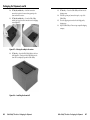
1
User’s Manual Cable Cubby® 200 Cable Cubby® 300C Cable Cubby® 300S Cable Cubby® 600 Cable Cubby® 800 Extron USA - West Headquarters +800.633.9876 Inside USA / Canada Only +1.714.491.1500 +1.714.491.1517 FAX Extron USA - East Extron Europe Extron Asia Extron Japan Extron China Extron Middle East +800.633.9876 +800.3987.6673 +800.7339.8766 +81.3.3511.7655 +81.3.3511.7656 FAX +400.883.1568 +971.4.2991800 +971.4.2991880 FAX +1.919.863.1794 +1.919.863.1797 FAX +31.33.453.4040 +31.33.453.4050 FAX +65.6383.4400 +65.6383.4664 FAX Inside USA / Canada Only Inside Europe Only Inside Asia Only © 2009 Extron Electronics. All rights reserved. Inside China Only +86.21.3760.1568 +86.21.3760.1566 FAX Surface Access Products for Cables, AAPs, and Power Outlets 68-701-01 Rev. I 06 09 Precautions Safety Instructions • English This symbol is intended to alert the user of important operating and maintenance (servicing) instructions in the literature provided with the equipment. This symbol is intended to alert the user of the presence of uninsulated dangerous voltage within the product’s enclosure that may present a risk of electric shock. Caution Read Instructions • Read and understand all safety and operating instructions before using the equipment. Retain Instructions • The safety instructions should be kept for future reference. Follow Warnings • Follow all warnings and instructions marked on the equipment or in the user information. Avoid Attachments • Do not use tools or attachments that are not recommended by the equipment manufacturer because they may be hazardous. Consignes de Sécurité • Français Ce symbole sert à avertir l’utilisateur que la documentation fournie avec le matériel contient des instructions importantes concernant l’exploitation et la maintenance (réparation). Ce symbole sert à avertir l’utilisateur de la présence dans le boîtier de l’appareil de tensions dangereuses non isolées posant des risques d’électrocution. Attention Lire les instructions• Prendre connaissance de toutes les consignes de sécurité et d’exploitation avant d’utiliser le matériel. Conserver les instructions• Ranger les consignes de sécurité afin de pouvoir les consulter à l’avenir. Respecter les avertissements • Observer tous les avertissements et consignes marqués sur le matériel ou présentés dans la documentation utilisateur. Eviter les pièces de fixation • Ne pas utiliser de pièces de fixation ni d’outils non recommandés par le fabricant du matériel car cela risquerait de poser certains dangers. Sicherheitsanleitungen • Deutsch Dieses Symbol soll dem Benutzer in der im Lieferumfang enthaltenen Dokumentation besonders wichtige Hinweise zur Bedienung und Wartung (Instandhaltung) geben. Dieses Symbol soll den Benutzer darauf aufmerksam machen, daß im Inneren des Gehäuses dieses Produktes gefährliche Spannungen, die nicht isoliert sind und die einen elektrischen Schock verursachen können, herrschen. Achtung Lesen der Anleitungen • Bevor Sie das Gerät zum ersten Mal verwenden, sollten Sie alle Sicherheits-und Bedienungsanleitungen genau durchlesen und verstehen. Aufbewahren der Anleitungen • Die Hinweise zur elektrischen Sicherheit des Produktes sollten Sie aufbewahren, damit Sie im Bedarfsfall darauf zurückgreifen können. Befolgen der Warnhinweise • Befolgen Sie alle Warnhinweise und Anleitungen auf dem Gerät oder in der Benutzerdokumentation. Keine Zusatzgeräte • Verwenden Sie keine Werkzeuge oder Zusatzgeräte, die nicht ausdrücklich vom Hersteller empfohlen wurden, da diese eine Gefahrenquelle darstellen können. Instrucciones de seguridad • Español Este símbolo se utiliza para advertir al usuario sobre instrucciones importantes de operación y mantenimiento (o cambio de partes) que se desean destacar en el contenido de la documentación suministrada con los equipos. Este símbolo se utiliza para advertir al usuario sobre la presencia de elementos con voltaje peligroso sin protección aislante, que puedan encontrarse dentro de la caja o alojamiento del producto, y que puedan representar riesgo de electrocución. Precaucion Leer las instrucciones • Leer y analizar todas las instrucciones de operación y seguridad, antes de usar el equipo. Conservar las instrucciones • Conservar las instrucciones de seguridad para futura consulta. Obedecer las advertencias • Todas las advertencias e instrucciones marcadas en el equipo o en la documentación del usuario, deben ser obedecidas. Evitar el uso de accesorios • No usar herramientas o accesorios que no sean especificamente recomendados por el fabricante, ya que podrian implicar riesgos. Warning Power sources • This equipment should be operated only from the power source indicated on the product. This equipment is intended to be used with a main power system with a grounded (neutral) conductor. The third (grounding) pin is a safety feature, do not attempt to bypass or disable it. Power disconnection • To remove power from the equipment safely, remove all power cords from the rear of the equipment, or the desktop power module (if detachable), or from the power source receptacle (wall plug). Power cord protection • Power cords should be routed so that they are not likely to be stepped on or pinched by items placed upon or against them. Servicing • Refer all servicing to qualified service personnel. There are no userserviceable parts inside. To prevent the risk of shock, do not attempt to service this equipment yourself because opening or removing covers may expose you to dangerous voltage or other hazards. Slots and openings • If the equipment has slots or holes in the enclosure, these are provided to prevent overheating of sensitive components inside. These openings must never be blocked by other objects. Lithium battery • There is a danger of explosion if battery is incorrectly replaced. Replace it only with the same or equivalent type recommended by the manufacturer. Dispose of used batteries according to the manufacturer’s instructions. Avertissement Alimentations• Ne faire fonctionner ce matériel qu’avec la source d’alimentation indiquée sur l’appareil. Ce matériel doit être utilisé avec une alimentation principale comportant un fil de terre (neutre). Le troisième contact (de mise à la terre) constitue un dispositif de sécurité : n’essayez pas de la contourner ni de la désactiver. Déconnexion de l’alimentation• Pour mettre le matériel hors tension sans danger, déconnectez tous les cordons d’alimentation de l’arrière de l’appareil ou du module d’alimentation de bureau (s’il est amovible) ou encore de la prise secteur. Protection du cordon d’alimentation • Acheminer les cordons d’alimentation de manière à ce que personne ne risque de marcher dessus et à ce qu’ils ne soient pas écrasés ou pincés par des objets. Réparation-maintenance • Faire exécuter toutes les interventions de réparationmaintenance par un technicien qualifié. Aucun des éléments internes ne peut être réparé par l’utilisateur. Afin d’éviter tout danger d’électrocution, l’utilisateur ne doit pas essayer de procéder lui-même à ces opérations car l’ouverture ou le retrait des couvercles risquent de l’exposer à de hautes tensions et autres dangers. Fentes et orifices • Si le boîtier de l’appareil comporte des fentes ou des orifices, ceux-ci servent à empêcher les composants internes sensibles de surchauffer. Ces ouvertures ne doivent jamais être bloquées par des objets. Lithium Batterie • Il a danger d’explosion s’ll y a remplacment incorrect de la batterie. Remplacer uniquement avec une batterie du meme type ou d’un ype equivalent recommande par le constructeur. Mettre au reut les batteries usagees conformement aux instructions du fabricant. Vorsicht Stromquellen • Dieses Gerät sollte nur über die auf dem Produkt angegebene Stromquelle betrieben werden. Dieses Gerät wurde für eine Verwendung mit einer Hauptstromleitung mit einem geerdeten (neutralen) Leiter konzipiert. Der dritte Kontakt ist für einen Erdanschluß, und stellt eine Sicherheitsfunktion dar. Diese sollte nicht umgangen oder außer Betrieb gesetzt werden. Stromunterbrechung • Um das Gerät auf sichere Weise vom Netz zu trennen, sollten Sie alle Netzkabel aus der Rückseite des Gerätes, aus der externen Stomversorgung (falls dies möglich ist) oder aus der Wandsteckdose ziehen. Schutz des Netzkabels • Netzkabel sollten stets so verlegt werden, daß sie nicht im Weg liegen und niemand darauf treten kann oder Objekte darauf- oder unmittelbar dagegengestellt werden können. Wartung • Alle Wartungsmaßnahmen sollten nur von qualifiziertem Servicepersonal durchgeführt werden. Die internen Komponenten des Gerätes sind wartungsfrei. Zur Vermeidung eines elektrischen Schocks versuchen Sie in keinem Fall, dieses Gerät selbst öffnen, da beim Entfernen der Abdeckungen die Gefahr eines elektrischen Schlags und/oder andere Gefahren bestehen. Schlitze und Öffnungen • Wenn das Gerät Schlitze oder Löcher im Gehäuse aufweist, dienen diese zur Vermeidung einer Überhitzung der empfindlichen Teile im Inneren. Diese Öffnungen dürfen niemals von anderen Objekten blockiert werden. Litium-Batterie • Explosionsgefahr, falls die Batterie nicht richtig ersetzt wird. Ersetzen Sie verbrauchte Batterien nur durch den gleichen oder einen vergleichbaren Batterietyp, der auch vom Hersteller empfohlen wird. Entsorgen Sie verbrauchte Batterien bitte gemäß den Herstelleranweisungen. Advertencia Alimentación eléctrica • Este equipo debe conectarse únicamente a la fuente/tipo de alimentación eléctrica indicada en el mismo. La alimentación eléctrica de este equipo debe provenir de un sistema de distribución general con conductor neutro a tierra. La tercera pata (puesta a tierra) es una medida de seguridad, no puentearia ni eliminaria. Desconexión de alimentación eléctrica • Para desconectar con seguridad la acometida de alimentación eléctrica al equipo, desenchufar todos los cables de alimentación en el panel trasero del equipo, o desenchufar el módulo de alimentación (si fuera independiente), o desenchufar el cable del receptáculo de la pared. Protección del cables de alimentación • Los cables de alimentación eléctrica se deben instalar en lugares donde no sean pisados ni apretados por objetos que se puedan apoyar sobre ellos. Reparaciones/mantenimiento • Solicitar siempre los servicios técnicos de personal calificado. En el interior no hay partes a las que el usuario deba acceder. Para evitar riesgo de electrocución, no intentar personalmente la reparación/mantenimiento de este equipo, ya que al abrir o extraer las tapas puede quedar expuesto a voltajes peligrosos u otros riesgos. Ranuras y aberturas • Si el equipo posee ranuras o orificios en su caja/alojamiento, es para evitar el sobrecalientamiento de componentes internos sensibles. Estas aberturas nunca se deben obstruir con otros objetos. Batería de litio • Existe riesgo de explosión si esta batería se coloca en la posición incorrecta. Cambiar esta batería únicamente con el mismo tipo (o su equivalente) recomendado por el fabricante. Desachar las baterías usadas siguiendo las instrucciones del fabricante. Extron’s Warranty Extron Electronics warrants this product against defects in materials and workmanship for a period of three years from the date of purchase. In the event of malfunction during the warranty period attributable directly to faulty workmanship and/or materials, Extron Electronics will, at its option, repair or replace said products or components, to whatever extent it shall deem necessary to restore said product to proper operating condition, provided that it is returned within the warranty period, with proof of purchase and description of malfunction to: USA, Canada, South America, and Central America: Extron USA 1001 East Ball Road Anaheim, CA 92805 U.S.A. Europe, Africa, and the Middle East: Extron Europe Hanzeboulevard 10 3825 PH Amersfoort The Netherlands Asia: Extron Asia 135 Joo Seng Road #04-01 PM Industrial Bldg. Singapore 368363 Singapore Japan: Extron Japan Kyodo Building, 16 Ichibancho Chiyoda-ku, Tokyo 102-0082 Japan China: Extron China 686 Ronghua Road, Songjiang District Shanghai 201611 China Middle East: Extron Middle East Dubai Airport Free Zone F12, PO Box 293666 United Arab Emirates, Dubai This Limited Warranty does not apply if the fault has been caused by misuse, improper handling care, electrical or mechanical abuse, abnormal operating conditions or nonExtron authorized modification to the product. If it has been determined that the product is defective, please call Extron and ask for an Applications Engineer at (714) 491-1500 (USA), 31.33.453.4040 (Europe), 65.6383.4400 (Asia), or 81.3.3511.7655 (Japan) to receive an RA# (Return Authorization number). This will begin the repair process as quickly as possible. Units must be returned insured, with shipping charges prepaid. If not insured, you assume the risk of loss or damage during shipment. Returned units must include the serial number and a description of the problem, as well as the name of the person to contact in case there are any questions. Extron Electronics makes no further warranties either expressed or implied with respect to the product and its quality, performance, merchantability, or fitness for any particular use. In no event will Extron Electronics be liable for direct, indirect, or consequential damages resulting from any defect in this product even if Extron Electronics has been advised of such damage. Please note that laws vary from state to state and country to country, and that some provisions of this warranty may not apply to you. 安全须知 • 中文 警告 这个符号提示用户该设备用户手册中 有重要的操作和维护说明。 电源 • 该 设 备 只 能 使 用 产 品 上 标 明 的 电 源 。 设 备 必须使用有地线的供电系统供电。 第三条线 (地线)是安全设施,不能不用或跳过。 这个符号警告用户该设备机壳内有暴 拔掉电源 • 为安全地从设备拔掉电源,请拔掉所有设备后 或桌面电源的电源线,或任何接到市电系统的电源线。 露的危险电压,有触电危险。 电源线保护 • 妥善布线, 避免被踩踏,或重物挤压。 注意 阅读说明书 • 用 户 使 用 该 设 备 前 必 须 阅 读 并 理 解所有安全和使用说明。 保存说明书 • 用户应保存安全说明书以备将来使 用。 遵守警告 • 用户应遵守产品和用户指南上的所有安 全和操作说明。 避免追加 • 不要使用该产品厂商没有推荐的工具或 追加设备,以避免危险。 维护 • 所有维修必须由认证的维修人员进行。 设备内部没 有用户可以更换的零件。为避免出现触电危险不要自己 试图打开设备盖子维修该设备。 通风孔 • 有些设备机壳上有通风槽或孔,它们是用来防止 机内敏感元件过热。 不要用任何东西挡住通风孔。 锂电池 • 不正确的更换电池会有爆炸的危险。 必须使用与 厂家推荐的相同或相近型号的电池。 按照生产厂的建 议处理废弃电池。 Table of Contents Chapter 1 • Introduction........................................................... 1-1 About the Cable Cubby® Products........................................ 1-2 Features......................................................................................... 1-5 Chapter 2 • Installation.............................................................. 2-1 Installation Overview. .............................................................. 2-2 Preparing the Routing Template........................................... 2-3 Preparing the Table. ................................................................. 2-4 Preparing the table with a router. ....................................... 2-4 Preparing the table with a hole saw (Cable Cubby 300C only)........................................................ 2-6 Installing the Cables and AAPs.............................................. 2-7 AAP shelf brackets (CC 300, 600, and 800). .......................... 2-7 Installing the power module (CC 300, 600, and 800)........... 2-8 Installing the cables................................................................ 2-8 Installing the AAPs................................................................. 2-9 Installing the shelf assembly (CC 300, 600, and 800)......... 2-10 Adjusting the cable position (CC 200)................................. 2-10 Mounting the Cable Cubby................................................... 2-11 Chapter 3 • Maintenance and Modifications. ............ 3-1 Removing and Replacing the Cable Cubby. ...................... 3-2 Replacing Cables or an AAP.................................................... 3-5 Adding an Additional Power Module (CC 600 and CC 800)................................................................... 3-6 Appendix A • Reference Information..............................A-1 Specifications...............................................................................A-2 Cable Cubby Part Numbers.....................................................A-7 Included Parts..............................................................................A-8 Replacement/Modification Part Numbers..........................A-9 Routing Template Part Numbers.........................................A-11 Top Plate Dimensions..............................................................A-11 Appendix B • Packaging for Shipment. .......................... B-1 Cable Cubby® Products • Table of Contents i Table of Contents, cont’d Cable Cubby® Products 1 Chapter One Introduction About the Cable Cubby® Products Features 68-701-01 Rev. I 06 09 All trademarks mentioned in this manual are the properties of their respective owners. ii Cable Cubby® Products • Table of Contents Introduction About the Cable Cubby® Products • Cable Cubby 200 (all models) — Two single-space AAPs The Extron Cable Cubby products are furniture-mounted, architectural solutions for inconspicuous cable access and connection points. When cables are not in use, they can be stored out of the way while remaining connected to the presentation system. Most US/domestic Cable Cubby models provide two unswitched USA AC power outlets. The US/domestic Cable Cubby 200 provides one outlet. Each of the international versions provides a single unswitched AC power outlet that is either universal or appropriate to the region where the Cable Cubby is sold. Several different types of power receptacles are available for the international version, including universal, UK, French, Israeli, Australian, Indian, European, and Swiss receptacles. N The Universal AC outlet is fully compatible with Europlug, British, Indian, Danish, and Italian plug types. See the universal AC outlet guide on the Extron Web site, www.extron.com, for compatibility details on all plug types. The four different sizes of Cable Cubby provide room for the indicated number of Extron’s Architectural Adapter Plates (AAPs): • Cable Cubby 800 USA/domestic model — Eight singlespace (single-height) AAPs • Cable Cubby 800 (international model) — Seven singlespace (single-height) AAPs • Cable Cubby 600 USA/domestic model — Six singlespace AAPs • Cable Cubby 600 (international model) — Five singlespace AAPs • Cable Cubby 300 USA/domestic model — Three singlespace AAPs • 1-2 Cable Cubby 300S — Square cover (figure 1-1) Cable Cubby 300C — Circular (round) cover Figure 1-1 — Cable Cubby 300S US/domestic enclosure The AAP spaces inside the Cable Cubby allow you to customize the enclosure to meet your unique needs, with the included split double space AAPs and the full line of optional Extron passive AAPs. The split AAPs can store almost any type of cable you might encounter. The line of passive AAPs allows you to customize the AAP with almost any kind of pass-through connectivity you may need. The elevation of the AAPs inside the cubby and the arrangement of the AAPs and the power outlets are adjustable to suit cable lengths and connector types. Cable Cubby 300 (international model) — Two singlespace AAPs Cable Cubby 300S — Square cover Cable Cubby 300C — Circular (round) cover Cable Cubby® Products • Introduction Cable Cubby® Products • Introduction 1-3 Introduction, cont’d N The elevation and arrangement of the power outlet and AAPs in the Cable Cubby 200 are fixed and not customizable. The installed Cable Cubby fits nearly flush within a table or podium top, storing the AAPs and cables out of the way and out of sight. To access the AAPs and connectors, lift the lid (figure 1-2). Half-moon cutouts in the lid allow you to run cables in or out and then close the lid. For Cable Cubby 300s, 600s, and 800s, you can lower the lid into its recessed position. Extron Cable Cubby 800 2 1 Figure 1-3 — Cable Cubby 300C mounting Features Hideaway Cable Access Enclosure 15-pin HD Cable Audio Cable, Network Cable Mounted through a table or podium • Easy access to cables and AAPs • Durable mechanical movement • Cable Cubby 300, 600, and 800 available in a variety of surface finishes • Compact size • Flexible installation of Extron passive AAPs • Grounded AC receptacle(s) • UL/c-UL listing • CSA certification • Fit in a range of surface thicknesses. See the table below: Enclosure Figure 1-2 — Typical Cable Cubby 800 application The Cable Cubby 300 is available with either a round or a rectangular top. The other Cable Cubby models all have rectangular tops only. Preparing the table to install a Cable Cubby 300C (round) requires simply drilling a hole in the table with a 6-inch hole saw (figure 1-3). Preparing the table to install a square cubby requires routing a square hole in the table top. Sheet metal routing templates are available (see "Routing Template Part Numbers", in appendix A, "Reference Information" for part numbers). 1-4 3 Cable Cubby® Products • Introduction Minimum table thickness Maximum table thickness Cable Cubby 200 0.375" (3/8") (9.53 mm) Cable Cubby 300 0.571" (≈19/32") [14.5 mm) 3.23" (≈3-1/4") [82.0 mm] Cable Cubby 600 0.75" (3/4") [19.05 mm] 3.41" (≈3-13/32") [86.6 mm] Cable Cubby 800 0.75" (3/4") [19.05 mm] 3.41" (≈3-13/32") [86.6 mm] Cable Cubby® Products • Introduction 1-5 Introduction, cont’d Cable Cubby® Products 2 Chapter Two Installation Installation Overview Preparing the Routing Template Preparing the Table Installing the Cables and AAPs Mounting the Cable Cubby 1-6 Cable Cubby® Products • Introduction Installation Installation Overview Preparing the Routing Template Install and set up the Cable Cubby enclosures as follows: 1 If you plan to use a mounting template that has not Extron offers metal templates for each Cable Cubby model; see "Routing Template Part Numbers", in appendix A, "Reference Information", for part numbers. Extron recommends using this template as a guide to cut the hole in the table where the cubby will be installed. 2 Cut a hole in the surface where the enclosure will be N been prepared, prepare the template. See "Preparing the Routing Template", on the next page. installed. See "Preparing the Table", later in this chapter. 3 Run all cables necessary to support the AC connector, the cables stored in the cubby, and all planned AAP connectors. Leave enough slack in the cables to connect or route them before the cubby is installed in the table. 4 If applicable, install the power module. If your location requires electrical conduit, install an Extron flexible conduit kit. Refer to the Flexible Conduit Kit Installation Guide, Extron part #68-734-01. The metal routing template is reusable. Do not discard this template when the installation is complete. Save it for installing Cable Cubby models of the same size. 1. Cut 1/2" x 4" strips of soft, finished lumber at least long enough to span the distance between the desired installation location on the mounting surface and the edges of the mounting surface (figure 2-1). These strips raise the routing template above the mounting surface to provide room for the router’s collar, protect the mounting surface, and extend the routing template’s reach so that it can be clamped to the edge of the surface. 5 Install all desired cables into the cable pass-through (split) Width of Mou AAPs and install the AAPs into the Cable Cubby. See "Installing the Cables and AAPs", later in this chapter. nting Surface 6 If applicable, connect cables to the rear connectors on the passive AAPs and install the AAPs in the cubby. See "Installing the AAPs", later in this chapter. Mounting Surface Edge Minimum 4 Screws Wood Strips 7 Mount the Cable Cubby in the table. See "Mounting the Cable Cubby", later in this chapter. 8 Peel the protective film from the top surface. Wood Strip Height 4" / 10.2 cm 9 Connect the Cable Cubby power cord. Routing Template Mounting Surface Edge Wood Thickness 0.5" / 1.3 cm Figure 2-1 — Prepared CC 300 mounting template 2. Using four or more short wood screws, secure the mounting template to the lumber strips. C 2-2 Cable Cubby® Products • Installation Do not allow the wood screws to protrude through the bottom of the wooden strips. Protruding screws will mar the table when the template is used. Cable Cubby® Products • Installation 2-3 Installation, cont’d Preparing the Table The preferred and recommended method for preparing the table for square Cable Cubby models and one of two preferred methods for the Cable Cubby 300C is to use the appropriate Extron routing template and a router. W 4. For the Cable Cubby 300C, another preferred method is to use a 6" hole saw. C The opening in the table for the Cable Cubby should be cut only by licensed and bonded craftspeople. Exercise care to prevent scarring or damaging the furniture. The surfaces of the Cable Cubby enclosure have screws and other protruding hardware that could damage fine furniture. Do not rest the enclosure on unprotected furniture. Wear safety glasses when operating the router. Failure to comply can result in eye injury. Using a router with a 5/8" (or 16 mm) outside diameter guide bushing and a 1/2" (or 12 mm or 12.7 mm) diameter straight router bit, carefully cut the opening in the surface (figure 2-2). Alternatively, for any model, you can use a paper cut-out template (see appendix A) and a sabre saw or keyhole saw; but this method is not recommended. Preparing the table with a router Prepare the table with a router as follows: C C N 2-4 The routing templates for the various Cable Cubby models are not interchangeable. If you use the wrong template, you will cut an improperly-sized hole. If you use a larger template than required, the cut will result in gaps in the table surface on either side of the enclosure. Figure 2-2 — Cutting the opening with a router 5. Remove the C-clamps and the routing template. Ensure that only the wooden strips on the routing template contact the furniture. Failure to do so may mar the furniture. The metal routing template is reusable. Do not discard the template when the installation is complete. Save it for installing other Cable Cubby models of the same size. 1. Mark the desired mounting location on the tabletop or other installation surface. 2. Place the mounting template assembly on the table, centered on the mounting location. Angle the template for the optimum positioning. If necessary, use a square to ensure that the template is properly positioned. Extron is not responsible for an improperly positioned Cable Cubby. 3. Once the template assembly is positioned properly, secure the assembly to the table with C-clamps. Cable Cubby® Products • Installation Cable Cubby® Products • Installation 2-5 Installation, cont’d Preparing the table with a hole saw (Cable Cubby 300C only) Prepare the table with a hole saw as follows: 1. On the tabletop or other installation surface, mark the 6" circle, then find and mark the center of the circle. W 2. Wear safety glasses when operating the drill. Failure to comply can result in eye injury. Using a portable drill with a 6" (or 152 mm) hole saw, carefully cut the opening in the table surface at the desired location (figure 2-3). Extron is not responsible for an improperly positioned Cable Cubby. C Installing the Cables and AAPs Each Cable Cubby 300, 600, and 800 model ships with one or two moveable AAP shelf assemblies. The Cable Cubby 200’s AAP shelf is fixed in place. AAP shelf brackets (CC 300, 600, and 800) Each shipped AAP shelf assembly consists of a set of shelf brackets and a number of cable pass-through (split) AAPs. Depending on the Cable Cubby model, each set of shelf brackets supports either two, three, or four single-space AAPs (figure 2-4). Use a portable drill with sufficient power to handle the 6” hole saw. Exercise caution when handling the drill and hole saw. Take care to protect the mounting surface from damage. Four-Space Shelf Bracket and Split AAPs Figure 2-3 — Cutting the opening with a hole saw Cable Cubby® Products • Installation Two-Space Shelf Bracket and Split AAPs Figure 2-4 — Shelf brackets The simplest way to install the cables and AAPs in the Cable Cubby 300, 600, and 800 is to populate the shelf brackets with split and/or standard AAPs outside the cubby and then install the populated AAP shelf assembly into the cubby. N 2-6 Three-Space Shelf Bracket and Split AAPs Cable Cubby 300, 600, and 800 only — On US/domestic models, the power module takes up two AAP spaces. On IEC, EU, Swiss, UK, Israeli, and Australian models, the power module takes up three AAP spaces. Cable pass-through AAPs take two, three, or four AAP spaces. Consider the arrangement of the Cable Cubby AAPs when you install them so that you do not waste AAP space. Cable Cubby® Products • Installation 2-7 Installation, cont’d Installing the power module (CC 300, 600, and 800) From the underside of the Cable Cubby, gently push the power module into the desired position at the desired elevation. Secure the power module into position with four Phillips head screws. N The Universal AC outlet is fully compatible with Europlug, British, Indian, Danish, and Italian plug types. See the universal AC outlet guide on the Extron Web site, www.extron.com, for compatibility details on all plug types. Installing the cables Three half-moon cutouts in each set of cable pass-through (split) AAPs loosely channel three cables in the Cable Cubby. Each channel is padded with a split grommet to prevent cable wear. Each channel and each associated split grommet is a different size (figure 2-5). Large Small Install cables in the channels as follows: 1. Remove a segment of a set of split AAPs by unscrewing the nuts on the underside of the bracket that fastens the plate to the shelf (CC 200) or shelf bracket (CC300, 600, or 800). See figure 2-4, on page 2-7. 2. Rest the cables in the half-moon cutouts of the split AAP segment still mounted on the shelf (CC 200) or shelf brackets (CC 300, 600, and 800). Place the cables so that the connectors that require inside Cable Cubby access protrude from the front (black side) of the split AAP segment. 3. Insert the screws of the split AAP segment that you removed in step 1 through the holes in the shelf bracket. Ensure that the cables are free in the channels that the two split AAP segments form without being pinched where the two segments meet. 4. Secure the split AAP segment to the shelf (CC 200) or shelf brackets (CC 300, 600, and 800) with the provided captive washers and #4-40 nuts. 5. Slip the appropriate size split grommet over each cable with the flange of the grommet toward the connector that will be accessible inside the Cable Cubby. Snap the grommets into the channels. 6. If applicable, snap the included hole plugs into unused channels in place of the split grommets. Small Medium Medium Medium Small Large Cable hole Large Medium Small 2-8 Large Hole size 0.625" (1.59 cm) 0.562" (1.43 cm) 0.5" (1.27 cm) Grommet size 0.453" (1.15 cm) 0.390" (0.99 cm) 0.312" (0.79 cm) Installing the AAPs The split AAPs can be replaced with passive Extron AAPs. Replace a set of split AAPs as follows: Figure 2-5 — Cable pass-through AAPs 1. A typical installation consists of a VGA cable, an audio cable, and a network cable. In a typical installation, the VGA cable runs in the largest channel, the network cable runs in the middle (medium) channel, and the audio cable runs in the smaller channel. In a non-standard installation, just match the diameter of the cable to the size of the channel as best you can. Remove the set of split AAPs to be replaced by unscrewing the nuts on the underside the shelf (CC 200) or shelf bracket (CC 300, 600, and 800) that fasten the plates to the bracket (figure 2-4, on page 2-7). 2. Cable the rear of the AAP(s) to be installed before attaching the AAPs to the enclosure. 3. Insert the screws of the AAPs through the holes in the shelf or shelf bracket. Secure the AAPs to the shelf brackets with the provided captive washers and #4-40 nuts. Cable Cubby® Products • Installation Cable Cubby® Products • Installation 2-9 Installation, cont’d Installing the shelf assembly (CC 300, 600, and 800) 3. Install a second stand-off, in accordance with steps 1 and 2. From the underside of the Cable Cubby, gently push the AAP shelf assembly into the desired position at the desired elevation. Ensure there is enough space above the AAP assembly for the Cable Cubby lid to close completely. Secure the AAP shelf assembly into position with four Phillips head screws. 4. Slide the stand-offs back and forth in the horizontal slots to position them so that the cables easily rise and lower but do not fall below the stand-offs. 5. Tighten the Phillips head screws to lock the stand-offs into position. N 6. Install and position the third stand-off, in accordance with steps 1 and 2 and 4 and 5 to secure the remaining cables. If the AAP shelf assembly does not slide easily into the cubby, loosen the AAP mounting nuts. Retighten the AAP mounting nuts once the AAP shelf assembly is installed in position. Adjusting the cable position (CC 200) The Cable Cubby 200 has three cable stand-offs (figure 2-6) that allow you to set the height of the cables inside the enclosure. Adjust the cable height as follows: Mounting the Cable Cubby W The flanged edges of the top of the surface enclosure are sharp. Exercise caution when the cubby is not installed in a table to prevent personal injury. C The flanged edges of the top of the cubby are bevelled to an ultra-fine thickness of less than 0.04 (4/100)” (approximately 1 mm). These edges are soft and can be easily nicked or bent. Exercise caution when handling and mounting the enclosure. Mishandling can damage the appearance of the enclosure. Cable Stand-Off 1. Loosen screws to adjust side to side. N 2. Remove screws to adjust height. Cable Cubby 300, 600, and 800 — If screw clamps are installed, remove them from both sides of the enclosure (figure 2-7 on page 2-12). Figure 2-7 shows the installation of a Cable Cubby 300C. Cable Cubby 300S, 600, and 800 installations are similar. Remove the plastic strips that protect the corners of the enclosure and the plastic film on the finished surfaces. If a sticky residue remains, remove it with an appropriate metal cleaning product. C Figure 2-6 — Cable Cubby 200 height adjustment 2-10 1. Insert the stand-off into the Cable Cubby and align the stand-off with one set of horizontal slots in the side of the enclosure. Choose the adjustment height that best lifts the cable connectors off of the cable pass-through AAP and still allows the lid to be closed. 2. Loosely install the Phillips head screws and washers as shown in figure 2-6. Cable Cubby® Products • Installation Do not use isopropyl alcohol or other solvents to clean the Cable Cubby. Strong solvents will ruin some finishes. Cable Cubby® Products • Installation 2-11 Installation, cont’d 3. Carefully lower the Cable Cubby into the hole to test the fit. If necessary, remove the enclosure and use a file or rasp to enlarge or smooth the edges of the opening (figure 2-7). 8. Cable Cubby 200 — Use the four included #6 wood screws to secure the Cable Cubby 200 to the table (figure 2-8). 15-pin HD Cable Cable Cubby 300C Audio Cable Surface-Mountable Enclosure for Cables, AAPs, and AC Power Outlet RJ-45 Cable Figure 2-8 — Cable Cubby, installation view Mounting Surface Screw Clamp Figure 2-7 — Cable Cubby 300C, installation view 4. Cable Cubby 300, 600, and 800 — From the underside of the table, reinstall the screw clamps on the enclosure at a height at which the clamp will reach the underside of the tabletop. C 2-12 Do not overtighten the Phillips head screws on the screw clamps. Overtightening can bend the horizontal flange of the screw clamp. 5. Cable Cubby 300, 600, and 800 — Snugly tighten the Phillips head screws on the screw clamps to secure the enclosure to the surface. 6. Cable Cubby 300, 600, and 800 — Tighten the locking thumbscrews on the screw clamps to lock the clamp in position. 7. Cable Cubby 200 — Drill 1/8" (3 mm) pilot holes 1/2" (12 mm) deep into the table in the mounting holes at each of the four corners of the cubby. Cable Cubby® Products • Installation Cable Cubby® Products • Installation 2-13 Installation, cont’d Cable Cubby® Products 3 Chapter Three Maintenance and Modifications Removing and Replacing the Cable Cubby Replacing Cables or an AAP Adding an Additional Power Module (CC 600, CC 800) 2-14 Cable Cubby® Products • Installation Maintenance and Modifications The Cable Cubby can be modified after installation to change cables, to replace an AAP, or to add a second power module. These modifications may require removing the cubby from the table. Removing and Replacing the Cable Cubby You may need to remove the cubby from the table in which it is mounted to replace cables or AAPs, to adjust the height of the AAP assemblies, or to install a second power module. Figure 3-1 shows removal of the Cable Cubby 300, 600, or 800 from the table and removal of the AAP shelf assembly and power module. N The Cable Cubby 200 is screwed to the top surface of the table. Its shelves are fixed in position and not removable. Remove and replace the Cable Cubby for maintenance as follows: W Ensure that AC power is disconnected before servicing the Cable Cubby. 1. Cable Cubby 300, 600, and 800 — Loosen the locking thumbscrews on the screw clamps to unlock the clamp (figure 3-1). 2. Cable Cubby 300, 600, and 800 — Loosen the screw clamps. 3. Cable Cubby 300, 600, and 800 — Remove the screw clamps on both sides of the enclosure. Extron Cable Cubby 800 Pins Screw Clamp Phillips Head Screw (Secures AAP Shelf Assembly and Power Module.) Figure 3-1 — Removing the cubby and its shelves 3-2 Cable Cubby® Products • Maintenance and Modifications Cable Cubby® Products • Maintenance and Modifications 3-3 Maintenance and Modifications, cont’d 4. Cable Cubby 200 — Remove the screws at the four corners that secure the cubby to the table (figure 3-2). 10. Cable Cubby 300, 600, and 800 — Snugly tighten the Phillips head screws on the screw clamps to secure the enclosure to the surface. 11. Cable Cubby 300, 600, and 800 — Tighten the locking thumbscrews on the screw clamps to lock the clamp in position. 12. Cable Cubby 200 — Fasten the Cable Cubby 200 to the table with the four 6-32 x 1/2" screws removed in step 4 (figure 3-2). Replacing Cables or an AAP Before you change the cables inside the cubby or replace one or more AAPs on Cable Cubby 300, 600, and 800 models, you must remove the AAP shelf assembly from the Cable Cubby. Use the following guidelines as applicable: Figure 3-2 — Removing the Cable Cubby 200 5. Lift the enclosure from the table. W The flanged edges of the top of the surface enclosure are sharp. Exercise caution when the cubby is not installed in a table to prevent personal injury. C The flanged edges of the top of the cubby are bevelled to an ultra-fine thickness of less than 0.04 (4/100)" (approximately 1 mm). These edges are soft and can be easily nicked or bent. Exercise caution when handling and mounting the enclosure. Mishandling can damage the appearance of the enclosure. 6. Remove the AAP shelf assembly(ies) or power module by removing the four Phillips head screws on the front and rear of the Cable Cubby and gently pushing the assembly out through the bottom of the cubby. 7 Perform the desired maintenance procedure. 8. Carefully lower the Cable Cubby into the hole in the table. 9. Cable Cubby 300, 600, and 800 — From the underside of the table, reinstall the screw clamps on the enclosure at a height at which the clamp will reach the underside of the tabletop. C 3-4 1 Cable Cubby 300, 600, and 800 — If the Phillips head screws on the front and rear of the cubby are blocked by the table, remove the cubby from the table. See "Removing and Replacing the Cable Cubby", steps 1 through 4, earlier in this chapter. 2 Cable Cubby 300, 600, and 800 — Remove the AAP shelf assembly(s) by removing the four Phillips head screws on the front and rear of the Cable Cubby and gently pushing the assembly out through the bottom of the cubby. 3 Change the cables and/or AAPs the same way you installed them. See "Installing the Cables and AAPs" in chapter 2, "Installation". 4 Cable Cubby 300, 600, and 800 — If you removed the cubby from the table, reinstall the surface mount enclosure. See "Removing and Replacing the Cable Cubby," steps 8 through 11, on the preceeding page. Do not overtighten the Phillips head screws on the screw clamps. Overtightening can bend the horizontal flange of the screw clamp Cable Cubby® Products • Maintenance and Modifications Cable Cubby® Products • Maintenance and Modifications 3-5 Maintenance and Modifications, cont’d Adding an Additional Power Module (CC 600 and CC 800) Figure 3-3 shows typical configurations before and after you add a second power module to an international Cable Cubby 600. Each additional power module occupies two (USA/domestic models) or three (international models) of the cubby’s AAP spaces, reducing the amount of AAP space available in the cubby for cable pass through (split) or passive AAPs. Use the following guidelines as applicable: N The Universal AC outlet is fully compatible with Europlug, British, Indian, Danish, and Italian plug types. See the universal AC outlet guide on the Extron Web site, www.extron.com, for compatibility details on all plug types. 1 Replacement two-space, three-space, and four-space shelf brackets and cable pass-through (split) AAPs are available from Extron, and may be required to maximize the remaining available space if you add a power module. • Cable Cubby 200 models — Adding a second power module is not possible. • Cable Cubby 300 models — Adding a second power module is not recommended. Depending on the model, with a second power module, there is either room left for only a single one-space AAP or no AAP space left at all. • Cable Cubby 600 and 800 international models — In general, you probably do not need replacement shelf brackets when you add an international module to an international Cable Cubby, because the power module replaces a three-space shelf that is standard in all international Cable Cubby models. After Before UNSWITCHED UNSWITCHED 230~50/60Hz 5A Two AAP Space Shelf Three AAP Space Shelf 230~50/60Hz 5A UNSWITCHED 230~50/60Hz 5A Two AAP Space Shelf Figure 3-3 — International Cable Cubby 600 with second power module Figure 3-4 shows typical configurations before and after you add a second power module to an international Cable Cubby 800. After Before UNSWITCHED Three AAP Space Shelf UNSWITCHED 230~50/60Hz 5A Four AAP Space Shelf 230~50/60Hz 5A UNSWITCHED 230~50/60Hz 5A Four AAP Space Shelf Figure 3-4 — International Cable Cubby 800 with second power module 3-6 Cable Cubby® Products • Maintenance and Modifications Cable Cubby® Products • Maintenance and Modifications 3-7 Maintenance and Modifications, cont’d Figure 3-6 shows typical configurations before and after you add a second US/Domestic power module to a US/domestic Cable Cubby 800 and suggests rack shelf configurations to replace the lost shelf space. After Before Figure 3-5 shows typical configurations before and after you add a second US/Domestic power module to a US/domestic Cable Cubby 600 and suggests rack shelf configurations to replace the lost shelf space. UNSWITCHED UNSWITCHED UNSWITCHED 100-240V/ 5AMAX 100-240V/ 5AMAX 100-240V/ 5AMAX UNSWITCHED UNSWITCHED UNSWITCHED 100-240V/ 5AMAX 100-240V/ 5AMAX 100-240V/ 5AMAX After Before UNSWITCHED UNSWITCHED 100-240V/ 5AMAX 100-240V/ 5AMAX 100-240V/ 5AMAX UNSWITCHED UNSWITCHED UNSWITCHED 100-240V/ 5AMAX 100-240V/ 5AMAX 100-240V/ 5AMAX Four AAP Space Shelf Four AAP Space Shelf Two AAP Space Shelf Four AAP Space Shelf or UNSWITCHED UNSWITCHED 100-240V/ 5AMAX 100-240V/ 5AMAX UNSWITCHED UNSWITCHED 100-240V/ 5AMAX 100-240V/ 5AMAX Four AAP Space Shelf AUDIO VIDEO Three AAP Space Shelf VIDEO Three AAP Space Shelf L AUDIO R UNSWITCHED R Cable Cubby 600 and 800 US/Domestic models — You probably do need replacement shelf brackets when you add a US/Domestic power module to a US/Domestic Cable Cubby, because the power module takes up two spaces in a cubby that, in its standard configuration, is equipped with three-space (Cable Cubby 600) or four-space (Cable Cubby 800) shelves. L • or UNSWITCHED UNSWITCHED 100-240V/ 5AMAX 100-240V/ 5AMAX UNSWITCHED UNSWITCHED 100-240V/ 5AMAX 100-240V/ 5AMAX Two AAP Space Shelf Two AAP Space Shelf Figure 3-5 — Cable Cubby 600 with second power module 3-8 Cable Cubby® Products • Maintenance and Modifications Three AAP Space Shelf Three AAP Space Shelf Figure 3-6 — Cable Cubby 800 with second power module 2 If the Phillips head screws on the front and rear of the cubby are blocked by the table, remove the cubby from the table. See "Removing and Replacing the Cable Cubby", steps 1 through 4, earlier in this chapter. 3 Before you add an additional power module, you must make room for the Cable Cubby by eliminating two or three AAP spaces and the AAP shelf brackets that support them. Remove the Phillips head screws on the front and rear of the Cable Cubby and gently push the assembly(ies) out through the bottom of the cubby. Cable Cubby® Products • Maintenance and Modifications 3-9 Maintenance and Modifications, cont’d 4 From the underside of the Cable Cubby, gently push the additional power module into the desired position at the desired elevation. Secure the power module into position with the included four Phillips head screws (figure 3-7). Extron Cable Cubby 600 2 Screws ea. side Push module through bottom of enclosure. Secure in place with screws. Figure 3-7 — Installing the power module 5 If desired, assemble and install replacement AAP shelf assemblies. Remember that the cable pull function of the Cable Cubby requires at least two AAPs. See "Installing the Cables and AAPs" in chapter 2, "Installation". 6 If you removed the cubby from the table, reinstall the surface mount enclosure. See "Removing and Replacing the Cable Cubby", steps 8 through 11, earlier in this chapter. Cable Cubby® Products A Appendix A Reference Information Specifications Cable Cubby Part Numbers Included Parts Replacement/Modification Part Numbers Routing Template Part Numbers Top Plate Dimensions 3-10 Cable Cubby® Products • Maintenance and Modifications Reference Information Specifications General Rack mount������������������������������������ No, but furniture mountable Enclosure type ������������������������������ Metal H H Enclosure dimensions C N Use the appropriate metal Extron routing template or refer to the surface cutout dimensions here before cutting a hole in the furniture or other surface. Pay special attention to the direction the unit will face; the unit’s AAP and connector access side is underlined. Extron is not responsible for miscut mounting holes. Architectural Adapter Plates (AAPs) are shown in the diagrams that follow and in photographs as examples only. AAPs are optional accessories for the Cable Cubby products. AAPs and cables must be ordered separately. H W D Cable Cubby 200 Cable Cubby 200 Top plate (outer rim)�������������������� 8.000" W x 4.394" D (20.32 cm W x 11.16 cm D) Surface cutout (inside rim)��������� 7.312 ±0.0325" W x 3.155 ±0.0325" D (18.57 ±0.083 cm W x 8.01 ±0.083 cm D) Box (under surface) ��������������������� 4.000" H x 7.120" W (front/rear of unit) x 2.974" D (10.16 cm H x 18.08 cm W x 7.55 cm D) A-2 Cable Cubby® Products • Reference Information W D Cable Cubby 300S W D Cable Cubby 300C Cable Cubby 300S Top plate (outer rim)�������������������� 5.130" W x 6.470" D (13.0 cm W x 16.4 cm D) Surface cutout (inside rim) �������� 4.625 ±0.0325" W x 5.970 ±0.0325" D (11.75 ±0.083 cm W x 15.16 ±0.083 cm D) Box (under surface) ��������������������� 6.410" H x 4.320" W (front/rear of unit) x 4.750" D without clamps (16.28 cm H x 10.97 cm W x 12.07 cm D) without clamps 6.410" H x 6.57" W x 4.750" D with clamps (16.28 cm H x 16.68 cm W x 12.07 cm D with clamps Cable Cubby 300C Top plate (outer rim) ������������������� 6.500" (16.51 cm) diameter circle Surface cutout (inside rim)��������� 6.000 ±0.0325" (15.24 ±0.083 cm) diameter circle Box (under surface) ��������������������� 6.410" H x 4.320" W (front/rear of unit) x 4.750" D without clamps (16.28 cm H x 10.97 cm W x 12.07 cm D) without clamps 6.410" H x 6.57" W x 4.750" D with clamps (16.28 cm H x 16.68 cm W x 12.07 cm D) with clamps Cable Cubby® Products • Reference Information A-3 Reference Information, cont’d H H W D Cable Cubby 600 Cable Cubby 600 Top plate (outer rim) ������������������� 6.960" W x 6.960" D (17.68 cm W x 17.68 cm D) Surface cutout (inside rim)��������� 6.460 ±0.0325" W x 6.460 ±0.0325" D (16.41 ±0.083 cm W x 16.41 ±0.083 cm D) Box (under surface) ��������������������� 6.410" H x 6.400" W (front/rear of unit) x 4.750" D without clamps (16.28 cm H x 16.26 cm W x 12.07 cm D) without clamps 6.410" H x 8.67" W x 4.750" D with clamps (16.28 cm H x 22.02 cm W x 12.07 cm D) with clamps A-4 Cable Cubby® Products • Reference Information W D Cable Cubby 800 Cable Cubby 800 Top plate (outer rim) ������������������� 8.360" W x 6.820" D (21.23 cm W x 17.32 cm D) Surface cutout (inside rim) �������� 7.860 ±0.0325" W x 6.320 ±0.0325" D (19.96 ±0.083 cm W x 16.05 ±0.083 cm D) Box (under surface) ��������������������� 6.410" H x 7.800" W (front/rear of unit) x 4.750" D without clamps (16.28 cm H x 19.81 cm W x 12.07 cm D) without clamps 6.410" H x 10.07" W x 4.750" D with clamps (16.28 cm H x 25.58 cm W x 12.07 cm D) with clamps Cable AAP cable hole diameters Large cable hole����������������� 0.63" (1.60 cm) Large grommet������������������ 0.45" (1.14 cm) Medium cable hole������������ 0.56" (1.42 cm) Medium grommet������������� 0.39" (0.99 cm) Small cable hole����������������� 0.50" (1.27 cm) Small grommet������������������ 0.31" (0.79 cm) Product weight Cable Cubby 200���������������� 2.5 lbs (1.1 kg) Cable Cubby 300S/300C�� 5.0 lbs (2.3 kg) Cable Cubby 600��������������� 9.0 lbs (4.1 kg) Cable Cubby 800��������������� 13.0 lbs (5.9 kg) Cable Cubby® Products • Reference Information A-5 Reference Information, cont’d Shipping weight Cable Cubby 200���������������� 4 lbs (2 kg) Cable Cubby 300S������������� 8 lbs (4 kg) Cable Cubby 300C������������� 8 lbs (4 kg) Cable Cubby 600��������������� 12 lbs (6 kg) Cable Cubby 800��������������� 15 lbs (7 kg) Vibration ���������������������������������������� ISTA 1A in carton (International Safe Transit Association) Listings, certifications������������������� UL, c-UL, CSA C/US Compliances����������������������������������� CE Warranty ���������������������������������������� 3 years parts and labor N Specifications are subject to change without notice. Cable Cubby Part Numbers Cable Cubby 200 Part number Cable Cubby 200 US/domestic (powder coat finish) 60-716-0A Cable Cubby 200S international (powder coat finish) 60-717-nn Cable Cubby 300S Part number Cable Cubby 300S US/domestic (black anodized finish) 60-526-0A Cable Cubby 300S international 60-712-nn Cable Cubby 300C Part number Cable Cubby 300C/domestic (black anodized finish) 60-527-0A Cable Cubby 300C international 60-713-nn Cable Cubby 600 Part number Cable Cubby 600 US/domestic (black anodized finish) 60-525-0A Cable Cubby 600 international 60-714-nn Cable Cubby 800 A-6 Cable Cubby® Products • Reference Information Part number Cable Cubby 800 US/domestic (black anodized finish) 60-524-0A Cable Cubby 800 international 60-715-nn N For the international versions, the nn in the part number identifies the AC power connector and finish (black anodized or brushed aluminum). Specify the desired power connector and finish when ordering. N All Cable Cubby 200 models are available in a powder coat finish only. N The USA versions of the Cable Cubby 300, 600, and 800 are also available in a brushed aluminum finish. Visit the Extron web site, www.extron.com, for more part numbers. Cable Cubby® Products • Reference Information A-7 Reference Information, cont’d Included Parts Replacement/Modification Part Numbers The Cable Cubby includes the Cable Cubby Products manual and a selection of shelf brackets, cable pass through AAPs, grommets, and hole plugs that vary depending on the Cable Cubby model. See the table below for included parts: ® Large Small Small Medium Medium Medium Small Large Power modules (CC 300, 600, 800) Part number Cable Cubby AC power module – USA 70-261-01 Cable Cubby AC power module – Swiss 70-262-01 Cable Cubby AC power module – Israel 70-388-01 Cable Cubby AC power module – Europe 70-264-01 Cable Cubby AC power module – Australia 70-265-01 Cable Cubby AC power module – UK 70-266-01 Cable Cubby AC power module – France 70-389-01 Cable Cubby AC power module – India 70-390-01 Cable Cubby AC power module – Universal 70-657-01 Large Cable pass-through AAPs AAP Cable Pass Through Left 70-270-01 AAP Cable Pass Through Left Middle 70-269-01 AAP Cable Pass Through Right Middle 70-268-01 AAP Cable Pass Through Right 70-267-01 AAP Shelf brackets Pass through AAPs* Grommets✝ Model 2 Pos. 3. Pos 4. Pos L M S L L-M R-M R 0✫ CC 200 US 0 0 1 0 0 1 1 1 1 0✫ CC 200 Int. 0 0 1 0 0 1 1 1 1 0 CC 300❖ US 2 0 1 0 1 2 2 2 2 2 CC 300❖ Int. 0 0 1 0 0 1 1 1 1 0 CC 600 US 4 0 2 2 2 2 5 5 5 2 CC 600 Int. 2 0 3 2 1 1 4 4 4 0 CC 800 US 0 4 2 3 3 2 7 7 7 0 CC 800 Int. 2 2 3 3 2 1 6 6 6 * L = left, L-M = left-middle, R-M = right midle, R = right ✝ L = large, M = medium, S = small ✫ Fixed two position shelf incorporated into the enclosure ❖ CC 300 S and CC 300 C have the same AAP configuration. Plugs✝ L M S 1 1 1 1 1 1 2 2 2 1 1 1 5 5 5 4 4 4 7 7 7 6 6 6 Part number N Each AAP cable pass-through kit listed below includes three grommets; one large, one medium, and one small. AAP cable pass through (right) (figure A-1) 70-267-01 AAP cable pass through (right-middle) (figure A-1) 70-268-01 AAP cable pass through (left-middle) (figure A-1) 70-269-01 AAP cable pass through (left) (figure A-1) 70-270-01 Large Small Small Medium Medium Medium Small Large AAP Cable Pass Through Left AAP Cable Pass Through Left Middle Large AAP Cable Pass Through Right Middle AAP Cable Pass Through Right Figure A-1 — Cable pass through AAPs A-8 Cable Cubby® Products • Reference Information Cable Cubby® Products • Reference Information A-9 Reference Information, cont’d AAP shelf brackets (CC 300, 600, 800) Part number Routing Template Part Numbers The following reuseable sheet metal routing templates are recommended for installation. Four-space AAP Cable Cubby bracket (set of 2) (figure A-2) 70-273-01 Three-space AAP Cable Cubby bracket (set of 2) (figure A-2) 70-272-01 Two-space AAP Cable Cubby bracket (set of 2) (figure A-2) 70-271-01 Template Single-space AAP Cable Cubby bracket (set of 2) (figure A-2) 70-392-01 Cable Cubby 200 routing template 70-384-01 Cable Cubby 300S/300C routing template 70-237-01 Cable Cubby 600 routing template 70-239-01 Cable Cubby 800 routing template 70-240-01 Part number Top Plate Dimensions There are two preferred and recommended methods for cutting the table: either use the appropriate metal routing template (see "Routing Template Part Numbers", above, for part numbers) (figure A-3 and chapter 2, "Installation") and a router or use a hole saw (Cable Cubby 300C only). Four-Space Shelf Bracket and Split AAPs Three-Space Shelf Bracket and Split AAPs Two-Space Shelf Bracket and Split AAPs Figure A-2 — Shelf brackets CABLE CUBBY 300 USER ACCESS Grommet and plug kit Part number N The kit listed below includes three grommets; one large, one medium, and one small. Grommet and hole plug kit 70-387-01 HSA 200 USER ACCESS HSA 200 CABLE CUBBY 300 Figure A-3 — CC 300S/300C metal routing template If you choose not to use the metal routing templates available from Extron, the cut-out templates (figure A-4, figure A-5, figure A-6, figure A-7, and figure A-8) will help you properly prepare the mounting surface. The cutout templates are not to scale and are for reference only. The surface cut-out area dimensions for the template are marked in bold type. For full size paper templates, visit the Extron Web site (www.extron.com) or call the Extron S3 Sales & Technical Support Hotline. A-10 Cable Cubby® Products • Reference Information Cable Cubby® Products • Reference Information A-11 Reference Information, cont’d Cut-Out Template for Extron's Cut-Out Template for Extron's Cable Cubby 200 Cable Cubby 300S 5.130" (13.0 cm) 4.394" (11.16 cm) .350" (0.90 cm) 4.625 + 0.0325" (11.75 + 0.083 cm) 3.155 + 0.0325" (8.01 + 0.083 cm) 6.470" (16.4 cm) User Access SURFACE CUT-OUT AREA = 3.155+ 0.0325" SURFACE CUT-OUT AREA = 4.625 + 0.0325" + 5.970" (11.75 cm) x 5.970 0.0325" + (15.16 0.083 cm) (15.2 cm) (8.01 + 0.083 cm) x 7.312 + 0.0325" (18.57 + 0.083 cm) 8.000" (20.32 cm) 7.312 + 0.0325" (18.57 + 0.083 cm) Cut surface material out along this line. 0.5" (1.3 cm) Top Panel User Access Cut-Out Radius: 0.25" (0.6 cm) TEMPLATE IS NOT FULL SIZE. Figure A-5 — Cable Cubby 300S cut-out template .350" (0.90 cm) Top Panel Cut-Out Radius: Cut surface material 0.25" out along this line. (0.6 cm) TEMPLATE IS NOT FULL SIZE. Figure A-4 — Cable Cubby 200 cut-out template A-12 Cable Cubby® Products • Reference Information Cable Cubby® Products • Reference Information A-13 Reference Information, cont’d Cut-Out Template for Extron's Cut-Out Template for Extron's Cable Cubby 600 Cable Cubby 300C 6.960" (17.68 cm) 6.460 + 0.0325" (16.41 + 0.083 cm) 6.500" Dia. (16.51 cm) 6.000 + 0.0325" Dia. (15.24 + 0.083cm) 6.960" (17.68 cm) 6.460 + 0.0325" (16.41 + 0.083 cm) SURFACE CUT-OUT AREA = 6.460 + 0.0325"(16.41 + 0.083 cm) x 6.460 + 0.0325"(16.41 + 0.083 cm) SURFACE CUT-OUT AREA = 6.000 + 0.0325" Dia. (15.24 + 0.083cm) Cut surface material out along this line. 0.5" (1.3 cm) Top Panel Cut-Out Radius: 0.25" (0.6 cm) User Access User Access TEMPLATE IS NOT FULL SIZE. TEMPLATE IS NOT FULL SIZE. Figure A-7 — Cable Cubby 600 cut-out template Figure A-6 — Cable Cubby 300C cut-out template A-14 Cable Cubby® Products • Reference Information Cable Cubby® Products • Reference Information A-15 Reference Information, cont’d Cut-Out Template for Extron's Cable Cubby® Products Cable Cubby 800 8.360" (21.23 cm) 7.860 + 0.0325" (19.96 + 0.083 cm) 6.820" (17.32 cm) 6.320 + 0.0325" (16.05 + 0.083 cm) SURFACE CUT-OUT AREA = 7.860 + 0.0325"(19.96 + 0.083 cm) x 6.320 + 0.0325"(16.05 + 0.083 cm) B Appendix B Cut surface material out along this line. 0.5" (1.3 cm) Top Panel Cut-Out Radius: 0.25" (0.6 cm) User Access TEMPLATE IS NOT FULL SIZE. Figure A-8 — Cable Cubby 800 cut-out template A-16 Cable Cubby® Products • Reference Information Packaging for Shipment Packaging for Shipment The Cable Cubby has ultra-fine machined surfaces and moving parts that make it vulnerable to damage caused by mishandling during shipment if it is improperly packaged. If, for any reason, you need to return a Cable Cubby to Extron, first contact Extron to obtain a return kit. The return kit, which reduces the chances of damage during shipment, includes a sturdy shipping carton and foam that can be fitted to each Cable Cubby model (figure B-1). Figure B-1 — Cable Cubby return kit Package a Cable Cubby for shipment as follows: 1. Contact the Extron S3 Sales & Technical Support Hotline to obtain a return kit. Extron will send the return kit to the location you specify. W C B-2 The flanged edges of the top of the surface enclosure are sharp when the Cable Cubby is removed from the table. Exercise caution when handling to prevent personal injury. The flanged edges of the top of the surface enclosure are bevelled to an ultra-fine thickness of less than 0.04 (4/100)” (approximately 1 mm). These edges are soft and can be easily nicked or bent. Exercise caution when handling and mounting the enclosure. Mishandling can damage the appearance of the enclosure. Cable Cubby® Products • Packaging for Shipment 2. Disconnect and retain all cables, remove and retain the AAP shelf assembly(s) (CC 300, 600, 800) and remove the Cable Cubby from the table or desk. See "Removing and Replacing the Cable Cubby", steps 1 through 4, in chapter 3, "Maintenance and Modifications". N 3. For Cable Cubby 300, 600, and 800 models, retain the screw clamps. Install the plastic strips that protect the flanged edges of the top of the surface enclosure (figure B-2). Figure B-2 — Installing protective strips N For Cable Cubby 200 models, proceed to step 13. For Cable Cubby 300, 600, and 800 models, continue to step 4, below. 4. Remove and retain the top foam pad from the carton. 5. CC 300, 600, and 800 only — Remove and discard the center foam section of the cushion in the carton (figure B-3). If you are returning a Cable Cubby 300 model, this is the correct fit. Proceed to step 8. Cable Cubby® Products • Packaging for Shipment B-3 Packaging for Shipment, cont’d Figure B-3 — Removing center foam 6. CC 600 and 800 only — Remove and discard the inner side foam sections of the cushion in the carton (figure B-4). If you are returning a Cable Cubby 600 model, this is the correct fit. Proceed to step 8. Figure B-4 — Removing inner side foams 7. B-4 CC 800 only — Remove and discard the outer side foam sections of the cushion in the carton (figure B-5). This is the correct fit for a Cable Cubby 800 model. Proceed to step 8. Cable Cubby® Products • Packaging for Shipment Figure B-5 — Removing outer side foams 8. If you will not install a replacement Cable Cubby in this location, remove and retain one of the small foam sections to the front or rear of the cubby opening in the cushion in the carton (figure B-6). Figure B-6 — Removing screw clamp area foam 9. CC 300, 600, and 800 only — Place the two screw clamps from step 2 into the screw clamp opening in the foam cushion in the carton. Cable Cubby® Products • Packaging for Shipment B-5 Packaging for Shipment, cont’d 10. CC 300, 600, and 800 only — Stuff the foam section removed in step 8 into the screw clamp opening in the foam cushion in the carton. 11. CC 300, 600, and 800 only — Lower the Cable Cubby, with the top closed, into the foam cushion in the shipping carton (figure B-7). 13. CC 200 only — Lower the Cable Cubby and foam into the shipping carton. 14. Place the top foam pad, removed in step 4, on top of the Cable Cubby. 15. Close the shipping carton and seal it with high quality shipping tape. 16. Ship the Cable Cubby to Extron using a reputable shipping company. Figure B-7 — Placing the cubby in the carton 12. CC 200 only — Insert the Cable Cubby 200 into the foam shell (figure B-8). Firmly push the Cable Cubby into the foam shell to completely suspend the Cable Cubby. Figure B-8 — Installing the foam shell B-6 Cable Cubby® Products • Packaging for Shipment Cable Cubby® Products • Packaging for Shipment B-7