1
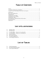
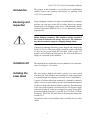
Preinstallation Manual
Verdi™ V-2/V-5/V-6
Diode-Pumped Lasers
5100 Patrick Henry Drive
Santa Clara, CA 95054
Verdi V-2/V-5/V-6 Laser Preinstallation Manual
This document is copyrighted with all rights reserved. Under the copyright
laws, this document may not be copied in whole or in part or reproduced in
any other media without the express written permission of Coherent, Inc.
Permitted copies must carry the same proprietary and copyright notices as
were affixed to the original. This exception does not allow copies to be
made for others, whether or not sold, but all the material purchased may
be sold, given or loaned to another person. Under the law, copying
includes translation into another language.
Coherent, the Coherent Logo, Verdi, and FAP-I are registered trademarks
of Coherent, Inc.
This product is sold by Coherent pursuant to a limited sublicense under
U.S. Patent No. Re 34,729. The rights which customers of Coherent
receive through purchase of this product are restricted, and exclude any
right to use the product in the telecommunications field.
Every effort has been made to ensure that the data given in this document
is accurate. The information, figures, tables, specifications and schematics
contained herein are subject to change without notice. Coherent makes no
warranty or representation, either expressed or implied with respect to this
document. In no event will Coherent be liable for any direct, indirect,
special, incidental or consequential damages resulting from any defects in
its documentation.
Technical Support
In the US:
Should you experience any difficulties with your laser or need any
technical information, please visit our web site www.coherent.com.
Additional support can be obtained by contacting our Technical Support
Hotline at 800-367-7890 (408-764-4557 outside the U.S.) or E-mail
([email protected]). Telephone coverage is available
Monday through Friday (except U.S. holidays and company shutdowns).
If you call outside our office hours, your call will be taken by our answering
system and will be returned when the office reopens.
If there are technical difficulties with your laser that cannot be resolved by
support mechanisms outlined above, please E-mail or telephone Coherent
Technical Support with a description of the problem and the corrective
steps attempted. When communicating with our Technical Support
Department, via the web or telephone, the model and Laser Head serial
number of your laser system will be required by the Support Engineer
responding to your request.
Outside the U.S.:
If you are located outside the U.S. visit our web site for technical
assistance or contact, by phone, our local Service Representative.
Representative phone numbers and addresses can be found on the
Coherent web site, www.coherent.com
Coherent provides telephone and web technical assistance as a service to
its customers and assumes no liability thereby for any injury or damage
that may occur contemporaneous with such services. These support
services do not affect, under any circumstances, the terms of any warranty
agreement between Coherent and the buyer. Operation of any Coherent
laser with any of its interlocks defeated is always at the operator's own risk.
ii
Table of Contents
TABLE OF CONTENTS
Preface ............................................................................................................................ iv
U.S. Export Control Laws Compliance .......................................................................... iv
Symbols Used in This Manual and on the Laser System .................................................v
Introduction.......................................................................................................................1
Receiving and Inspection..................................................................................................1
Installation Kit ..................................................................................................................1
Installing the Laser Head ..................................................................................................1
Installing the Power Supply ..............................................................................................5
Installing the Chiller .........................................................................................................6
Final Installation and Initial Turn-On Procedures ............................................................6
External Interlock .............................................................................................................7
Dimensions .......................................................................................................................9
LIST OF ILLUSTRATIONS
1-1
1-2
1-3
1-4
1-5
1-6
1-7
1-8
Installation Kit ...............................................................................................................2
Riser/Heatsink................................................................................................................4
Laser Head Base – Protective Cover Installed...............................................................4
Laser Head Base – Protective Cover Removed .............................................................5
External Interlock ..........................................................................................................7
Interconnect Diagram ....................................................................................................8
Laser Head Dimensions .................................................................................................9
Power Supply Dimensions...........................................................................................10
LIST OF TABLES
1-1
1-2
1-3
Utility Requirements......................................................................................................8
Environmental Requirements ........................................................................................9
Laser System Dimensions..............................................................................................9
iii
Verdi V-2/V-5/V-6 Laser Preinstallation Manual
Preface
This manual contains user information for the Verdi™ V-2/V-5/V-6
Diode-Pumped Lasers.
Read the Operator’s Manual carefully before operating the
laser for the first time. Special attention should be given to the
material in Section One, Laser Safety, that describes the safety
features built into the laser.
Use of controls or adjustments or performance of procedures
other than those specified in this manual may result in
hazardous radiation exposure.
Use of the system in a manner other than that described herein
may impair the protection provided by the system.
U.S. Export
Control Laws
Compliance
It is the policy of Coherent to comply strictly with U.S. export
control laws.
Export and re-export of lasers manufactured by Coherent are subject
to U.S. Export Administration Regulations, which are administered
by the Commerce Department. In addition, shipments of certain
components are regulated by the State Department under the International Traffic in Arms Regulations.
The applicable restrictions vary depending on the specific product
involved and its destination. In some cases, U.S. law requires that
U.S. Government approval be obtained prior to resale, export or
re-export of certain articles. When there is uncertainty about the
obligations imposed by U.S. law, clarification should be obtained
from Coherent or an appropriate U.S. Government agency.
iv
Preface
Symbols Used in
This Manual and
on the Laser
System
This symbol is intended to alert the operator to the danger of
exposure to hazardous visible laser radiation.
This symbol is intended to emphasize the presence of important
operating instructions.
v
Verdi V-2/V-5/V-6 Laser Preinstallation Manual
vi
Verdi V-2/V-5/V-6 Laser Preinstallation Manual
Introduction
The purpose of this document is to assist the user in establishing a
suitable location and operating environment for optimum Verdi
V-2/V-5/V-6 performance.
Receiving and
Inspection
Inspect shipping containers for signs of rough handling or damage.
Indicate any such signs on the bill of lading. Report any damage
immediately to the shipping carrier, and to Coherent Order Administration Department (800-438-6323) or to an authorized Coherent
representative.
Retain shipping containers. The containers will be required if
the system is returned to the factory for service. The containers
may also be needed to support a shipping damage claim.
Coherent recommends that three people unpack and transport the
Verdi V-2/V-5/V-6. The power supply weighs70 pounds and should
be lifted by two people while the laser head, which weighs 22.2
pounds, can be lifted by the third person. The laser head and power
supply are connected by the umbilical.
Installation Kit
The installation kit contains the necessary hardware for Verdi installation. See Figure 1-1 for details.
Installing the
Laser Head
The laser head is shipped with either a passive or a water-cooled
riser/heat sink. This riser/heat sink maintains the Verdi output beam
at a suitable height for pumping a laser such as the Coherent Mira.
A passive riser/heat sink when mounted on a thermally conductive
surface (such as an optical table) provides sufficient heat dissipation
for the laser head under normal ambient conditions. The temperature
of the laser head baseplate is monitored by the Verdi power supply
and can be displayed on the power supply front panel. Power dissipation through the baseplate is typically 20 to 25 Watts (30 Watts
maximum). The Verdi will shut down if the baseplate temperature
exceeds 55°C.
An optional water-cooled riser/heat sink is available for use with a
chiller.
1
Verdi V-2/V-5/V-6 Laser Preinstallation Manual
2
3
5
7
10
6
9
8
1
4
1.
Riser/heat sink installation hardware
6.
Interlock-disassembled
2.
Operator’s manual
7.
Fuses and instructions
3.
AC power cord
8.
4.
Power supply key
FAP-I installation hardware, including shorting clips,
end caps, etc.
5.
Installation kit case
9.
Laser head/heat sink mounting hardware
10. Dowel pins – laser head/heat sink
Figure 1-1. Installation Kit
2
Verdi V-2/V-5/V-6 Laser Preinstallation Manual
The laser head is shipped with a protective plastic plate installed
over the baseplate. Leave the plastic plate in place until laser head is
ready for installation.
1.
Remove the packing material from the riser/heat sink
(Figure 1-2).
2.
Insert two dowel pins (Figure 1-1 , item 12) into the riser/heat
sink dowel holes (Figure 1-2, item 1), ball-end up.
Avoid damage to the laser head baseplate, which is milled to a
flatness of ± 0.1 mm. This tolerance provides maximum thermal
conduction between the baseplate and the mounting surface.
Keep the umbilical as straight as possible while avoiding
rotating the laser head with respect to the power supply.
Do not apply thermal compound or any other material on the
laser head baseplate or on the riser/heat sink.
3.
Remove the laser head and power supply from the shipping
crate. Place the laser head on its side and on a protected surface
to avoid scratching the cover as shown on Figure 1-3. Remove
the three screws (Figure 1-3, item 2) securing the protective
plastic cover (item 4) to the laser head baseplate. Any
scratches, damage, or contamination of the baseplate will
reduce the thermal conduction between the baseplate and the
mounting surface.
4.
Refer to Figure 1-4 for the laser head dowel pin positions.
Carefully place the laser head over the riser/heat sink and onto
the dowel pins.
Do not use excessive force when clamping the Verdi to the
riser/heat sink.
5.
Use four laser head clamps (Figure 1-1 item 9) to secure the
laser head to the riser/heat sink. Tighten the 4 clamps firmly
using an Allen head wrench.
3
Verdi V-2/V-5/V-6 Laser Preinstallation Manual
1
2
3
4
1.
Dowel holes (2)
3.
2.
Cooling water inlet and outlet (if included) 4.
Laser head clamp screw holes (4)
Optical table clamp mounts (4)
Figure 1-2. Riser/Heatsink
1
4
3
2
1.
Laser head
3.
Protective material
2.
Protective plastic cover retaining screws (3)
4.
Protective plastic cover
Figure 1-3. Laser Head Base – Protective Cover Installed
4
Verdi V-2/V-5/V-6 Laser Preinstallation Manual
DOWEL PIN HOLES
Figure 1-4. Laser Head Base – Protective Cover Removed
Installing the
Power Supply
6.
Proceed to the paragraph titled, “Installing the Power Supply”.
The riser/heat sink clamps and chiller connection will be
installed during the final installation procedures.
1.
Move the power supply to an accessible-friendly location,
preferably away from heat producing sources. Ensure the
cooling intake and exhaust (rear, top, and left side) are not
blocked or obstructed.
If storing the power supply in a 19 in. (48 cm) equipment rack,
allow a minimum horizontal clearance of 17.937 in.
(45.56 cm) for the front panel of the power supply.
The system will not operate with the interlock open. For additional information on the interlock, including the connection of
an external interlock circuit, refer to the paragraph titled,
“External Interlock”.
2.
Connect the interlock connector (Figure 1-1, item 6) on the
rear of the power supply.
The interlock connector may be located in the installation kit
or may be attached to the umbilical.
3.
Connect the AC power cord on the rear of the power supply.
Do not connect the AC power cord at this time.
5
Verdi V-2/V-5/V-6 Laser Preinstallation Manual
Each customer must inspect the power cord and install the
proper connector if necessary. The connector should be
installed in a properly grounded outlet with a maximum of
10 Ampere service @ 110 V and 11 Ampere service @ 220 V
for proper overcurrent and earth fault protection.
4.
Final Installation
and Initial
Turn-On
Procedures
Proceed to the paragraph titled, “Final Installation and Initial
Turn-On Procedures”.
After installing the laser head and power supply in accordance with
paragraphs titled, “Installing the Laser Head” and “Installing the
Power Supply”, complete the installation as follows:
1.
Position the power supply and laser head in the operating position with the umbilical as straight as possible. Ensure that the
umbilical has a bend radius of 5 inches or greater. A distance
of 6 to 24 inches is recommended between the Verdi output
and any laser being pumped.
Excessively tight umbilical bends (less than a 5 inch radius) can
cause permanent damage to the optical fiber.
2.
If a water-cooled system is used, position the chiller in the
operating position. Fill and prepare the chiller in accordance
with the chiller user’s manual.
3.
Cut the user-supplied cooling water lines to the appropriate
lengths and use the water line hardware (Figure 1-1, item 9) to
connect the riser/heat sink to the chiller (Figure 1-6). Apply
teflon tape to the hardware threads and install the washers from
the installation kit over the threads when connecting the stainless steel ferrule to the riser/heat sink. Check the system for
leaks.
4.
If a passive riser/heat sink will be used, ensure the riser/heat
sink is mounted on a thermally conductive surface (such as an
optical table) that provides sufficient heat dissipation to maintain the laser head baseplate below 55°C, preferably below
40°C.
5.
Use four riser/heat sink clamps (Figure 1-1, item 1) to secure
the system to the optical table. Tighten the two front clamps
firmly using an Allen head wrench. Tighten the two rear
clamps finger tight only.
6.
Connect power supply to facility power. Ensure all packing
materials have been removed.
6
Verdi V-2/V-5/V-6 Laser Preinstallation Manual
7.
External
Interlock
Perform the procedure in paragraph titled, “Turn-on
(Cold-Start)” in the Operator’s Manual.
The system will not operate with the interlock open. An interlock
connector is located on the power supply rear panel. The interlock
status is monitored by the CPU. If the interlock is open, the message,
“External Interlock Fault” will be displayed on the power supply
front panel.
An external interlock circuit can be connected to the laser system
and wired to a door switch to provide additional operating safety.
When the door is opened, the laser will shut down. Press MENU
EXIT key to clear the fault and continue operation.
To incorporate an external safety interlock circuit into the laser
system, perform the following steps:
1.
Turn off the laser system. Locate and remove the Interlock
connector from the back of the Verdi power supply. This type
of connector is called a “three pin mini-DIN”.
2.
Slide the plastic cover off of the connector. Locate the two pins
that have a wire soldered between them. These are pins 1 and
2. Remove the shorting wire and solder your interlock wires to
these two pins. Make sure the wires have adequate strain relief.
3.
Solder the other ends of the wires to an interlock switch. You
can use many types of switches. The switch must be of a type
that has its contacts closed when it is safe to operate the laser
and open when it is not safe.
4.
Figure 1-5 shows the wiring diagram for the switch. One wire
runs from pin 1 of the connector to the normally open contact
of the switch. The other wire runs from pin 2 to the common
terminal of the switch. The switch is shown in the open position. This is the condition in which you do not want the laser
beam to operate.
Figure 1-5. External Interlock
7
Verdi V-2/V-5/V-6 Laser Preinstallation Manual
5.
The interlock circuit in Verdi operates from a +/-12 VDC
circuit. Its current is limited to around 1 mA. For these ratings,
a “dry-circuit” type switch will give the most reliable operation.
UMBILICAL
AIR COOLED
POWER SUPPLY
LASER HEAD
FACILITY
POWER
WATER LINES (if using Water Cooling)
CHILLER
FACILITY
POWER
Figure 1-6. Interconnect Diagram
Table 1-1. Utility Requirements
PARAMETER
REQUIREMENT
Power Requirements
100 to 240 VAC[1][2]
Maximum Current
6.5 Amps @ 100 VAC
7 Amps @ 220 VAC
Cooling:
Laser head:
Riser/heat sink[3]
Power supply:
Air-cooled with ambient air
Note: All specifications and requirements are subject to change without notice.
[1] The power supply is autoranging and will accommodate the full range of input voltages without hardware
changes.
[2] The electrical service should have a main power disconnect switch located in close proximity to the laser. The
main power disconnect switch shall be clearly marked as the disconnecting device for the laser, and shall be
within easy reach of the operator.
[3] The passive riser/heat sink must be mounted on a conductive surface capable of maintaining the laser head baseplate at less than 55°C. An optional riser/heat sink and chiller or chill plate can also be used. Refer to the paragraph titled, Installing the Laser Head, for additional information on removing waste heat from the laser head.
8
Verdi V-2/V-5/V-6 Laser Preinstallation Manual
Table 1-2. Environmental Requirements
PARAMETER
REQUIREMENT
Operating temperature
15 to 35°C (59 to 95°F)
Relative humidity
5 to 95% (non condensing)
Altitude
Sea level to 10,000 feet
Dimensions
Figure 1-7. Laser Head Dimensions
9
Verdi V-2/V-5/V-6 Laser Preinstallation Manual
Figure 1-8. Power Supply Dimensions
10
Verdi V-2/V-5/V-6 Laser Preinstallation Manual
11
Verdi V-2/V-5/V-6 Lasers Preinstallation Manual
© Coherent, Inc. 09/2005, Printed in the U.S.A.
Part No. 0171-796-00, Rev DB