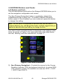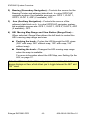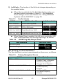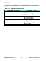
1
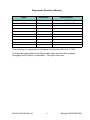
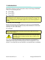
Cirrus
EXP5000
Primary Flight Display
Pilot’s Guide
600-00142-000 Rev 01
Document Revision History
Date
Revision
Description
Sept. 30, 2005
00
Released per ECO-05-162
Oct. 14, 2005
01
Updated per ECO-05-179
This document is applicable to Software Part Number 530-00177-000.
All materials copyrighted including images that represent this software
Copyright 2005 Avidyne Corporation. All rights reserved.
600-00142-000 Rev 01
-i-
Entegra EXP5000 PFD
Table of Contents
1 Introduction .............................................................. 1
Notes and Warnings 1
Copyrights and Trademarks 2
AVIDYNE EXCLUSIVE LIMITED WARRANTY/LIMITATIONS ON
LIABILITY .................................................................................... 3
2 EXP5000 System Overview ..................................... 5
Entegra EXP5000 Overview 5
EXP5000 Upper Half Display ...................................................... 7
Upper Half Display ................................................................ 7
EXP5000 Display Options................................................... 10
EXP5000 Lower Half Display .................................................... 12
HSI (120° View) .................................................................. 14
EXP5000 Buttons and Knobs .................................................... 15
Left Buttons and Knob......................................................... 15
Nav, Bearing, and Aux Data Blocks .................................... 17
Right Buttons and Knob ...................................................... 19
3 Flying with the EXP5000........................................ 22
Introduction 22
Starting the EXP5000 ................................................................ 23
EXP5000 Alignment Messages........................................... 24
AHRS Alignment Errors ...................................................... 25
Startup Settings ........................................................................ 26
Setting Up the HSI..................................................................... 27
Using GPS/VHF Systems with the EXP5000 ............................ 29
Controlling the Autopilot ............................................................ 30
Horizontal Modes ................................................................ 30
Vertical Modes .................................................................... 32
About Flight Director (S-TEC 55X only) .............................. 33
Precision Flying with EXP5000.................................................. 35
Obtaining Level Flight ......................................................... 35
Flying a Constant Rate Turn ............................................... 35
Using Trend Indicators ........................................................ 36
Using the EXP5000 for Approaches.......................................... 38
Precision Approaches ......................................................... 38
Non-Precision Approaches ................................................. 39
Missed Approach ................................................................ 40
600-00142-000 Rev 01
-ii-
Entegra EXP5000 PFD
4 Invalid Sensors and Error Conditions ................. 41
Invalid Air Data .......................................................................... 42
Invalid Heading.......................................................................... 43
Crosscheck Monitor................................................................... 44
Warmstart Conditions ................................................................ 45
Recoverable Attitude ................................................................. 46
Invalid Attitude & Heading ......................................................... 47
Invalid Engine Data ................................................................... 48
Nav Source Crosscheck ............................................................ 49
5 Software License ................................................... 50
600-00142-000 Rev 01
-iii-
Entegra EXP5000 PFD
This page intentionally blank.
Entegra EXP5000 PFD
-iv-
600-00142-000 Rev 01
1 Introduction
This Pilot’s Guide provides information about the Entegra EXP5000
PFD for the following aircraft:
●
Cirrus SRV
●
Cirrus SR20
●
Cirrus SR22
Note: All images contained within this document, including screenshots and
other displays, are for reference use only and are subject to change. The
images contained herein may differ slightly from your actual equipment or
display.
1.1 Notes and Warnings
Notes and warnings provide guidance for the use of the EXP5000.
Avidyne strongly suggests that you pay close attention to notes and
warnings for your own safety.
For example:
Note: Notes provide useful information about how to use the EXP5000
Primary Flight Display.
!
Warnings are prefaced with exclamation points and denote
information that can prevent serious injury or death on the
part of the user.
The instructions and warnings in this manual are not intended to
replace the instructions and warnings for other equipment on your
aircraft. It is critical that you as the pilot in command have a complete
600-00142-000 Rev 01
-1-
Entegra EXP5000 PFD
Introduction
understanding of the warnings, operating instructions, and limitations
for all equipment installed on your aircraft.
!
!
This manual assumes that the reader is an appropriately
licensed pilot. Avidyne strongly recommends that you use the
EXP5000 only under VFR conditions until you are very familiar
with the EXP5000.
If you have questions, please contact Avidyne at 800-2843963 (800-AVIDYNE) before operating with the Entegra PFD
under IFR conditions.
When using the EXP5000, be sure to cross-check the data
displayed against other data sources for accuracy including
other flight deck instruments and charts.
1.2 Copyrights and Trademarks
All trademarks and trade names are the property of their respective
owners.
All materials copyrighted including images that represent this
software.
Copyright 2005 Avidyne Corporation. All rights reserved.
Entegra EXP5000 PFD
-2-
600-00142-000 Rev 01
AVIDYNE EXCLUSIVE LIMITED WARRANTY/LIMITATIONS ON LIABILITY
1.3 AVIDYNE EXCLUSIVE LIMITED WARRANTY/
LIMITATIONS ON LIABILITY
Avidyne warrants the Product manufactured by it against defects in material and
workmanship for a period of twenty-four (24) months from delivery. If Avidyne's
Product fails to conform to this warranty, Avidyne, in its sole discretion, will either
repair or replace the Product or provide a refund of the purchase price paid for the
Product. This warranty is made upon the express conditions that:
(a) Avidyne is given prompt written notice of any claimed non-conformity in the
Product, with a reasonable explanation thereof;
(b) The Product is returned to Avidyne or to an Avidyne authorized service facility;
(c) The Product has not been altered in any manner other than as previously authorized
by Avidyne in writing; and
(d) Repairs to the Product have not been made by anyone other than Avidyne or an
Avidyne authorized service facility.
This warranty does not apply to any Product which is not installed, maintained and
operated in accordance with Avidyne's written instructions or which is otherwise
misused, including, without limitation, to any Product which is damaged due to
improper installation, maintenance or operation, tampering, alteration of serial numbers
or other manufacturers data, lightning or other electrical source, or otherwise.
If warranty protection is applicable to the Product, Avidyne will use reasonable efforts
to repair or replace Product within ten (10) business days of its receipt of the Product.
Any Product that has been repaired by Avidyne or replaced by Avidyne under this
warranty will be subject to remainder of the original warranty term applicable to the
repaired or replaced Product or will be warranted under the warranty terms above for
ninety days from the date of repair or replacement, whichever period is longer.
THIS EXCLUSIVE LIMITED WARRANTY APPLIES IN LIEU OF AND EXPRESSLY
SUPERCEDES AND EXCLUDES ALL OTHER REPRESENTATIONS, AFFIRMATIONS
AND/OR WARRANTIES, WHETHER EXPRESS OR IMPLIED, ORAL OR WRITTEN,
INCLUDING, WITHOUT LIMITATION, ANY WARRANTY OF MERCHANTABILITY, OF
FITNESS FOR A PARTICULAR PURPOSE, OF TITLE AND/OR OF NON-INFRINGEMENT.
PURCHASER EXPRESSLY AND KNOWINGLY AGREES THAT NO OTHER
REPRESENTATIONS, AFFIRMATIONS OR WARRANTIES, WHETHER EXPRESS OR
IMPLIED, ORAL OR WRITTEN, FORM PART OF ANY PURCHASE AND SALE
TRANSACTION RELATED TO THE PRODUCT.
AVIDYNE'S (AND ITS AFFILIATES') AND ANY PRODUCT COMPONENT SUPPLIER'S
SOLE RESPONSIBILITY AND LIABILITY RELATED TO THE PRODUCT OR ARISING OUT
OF OR RELATED TO ITS PURCHASE, SALE, PERFORMANCE, RELIABILITY OR USE
ARE LIMITED TO ITS REPAIR OR REPLACEMENT, OR TO A REFUND OF THE
PURCHASE PRICE, IN AVIDYNE'S SOLE DISCRETION. IN NO EVENT WILL AVIDYNE
(OR ITS AFFILIATES) OR ANY SUPPLIERS OF PRODUCT COMPONENTS BE
RESPONSIBLE OR LIABLE FOR ANY OTHER DAMAGE OF ANY NATURE
WHATSOEVER, INCLUDING DIRECT, INDIRECT, INCIDENTAL, CONSEQUENTIAL,
SPECIAL, LOSS OF USE, LOSS OF REVENUE OR PROFIT, PROPERTY DAMAGE,
PERSONAL INJURY, WRONGFUL DEATH, OR OTHER DAMAGE (WHETHER OR NOT
600-00142-000 Rev 01
-3-
Entegra EXP5000 PFD
Introduction
AVIDYNE (OR ITS AFFILIATES) WERE NOTIFIED OF THE POSSIBILITY THAT ANY
DAMAGE MIGHT BE INCURRED), ARISING OUT OF OR RELATED TO THE PRODUCT,
ITS PURCHASE OR SALE, ITS PERFORMANCE OR RELIABILITY, OR THE USE OR
INABILITY TO USE THE PRODUCT, FOR ANY REASON, INCLUDING DUE TO ANY
PRODUCT DEFECT OR DEFECTS OR ANY ACTION OR INACTION OF ANY NATURE
(INCLUDING CLAIMED OR ACTUAL NEGLIGENCE OR GROSS NEGLIGENCE) BY
AVIDYNE OR ANY SUPPLIERS OF PRODUCT COMPONENTS. NEITHER THIS
EXCLUSIVE LIMITED WARRANTY NOR AVIDYNE'S OR ANY PRODUCT COMPONENT
SUPPLIER'S RESPONSIBILITY OR LIABILITY WILL IN ANY WAY BE ENLARGED OR
OTHERWISE ALTERED DUE TO AVIDYNE'S PROVISION OF TECHNICAL SUPPORT OR
TRAINING RELATED TO THE PRODUCT.
WITHOUT LIMITING THE FOREGOING, NEITHER AVIDYNE (NOR ITS AFFILIATES)
MAKE ANY REPRESENTATIONS, AFFIRMATIONS OR WARRANTIES REGARDING OR
RELATED TO PRODUCTS NOT MANUFACTURED BY AVIDYNE OR REGARDING OR
RELATED TO THE PERFORMANCE OR RELIABILITY OF ANY SUCH PRODUCT, EITHER
ALONE OR WHEN USED WITH ANY PRODUCT MANUFACTURED BY AVIDYNE, OR THE
SUITABILITY OF ANY SUCH PRODUCT FOR USE WITH ANY PRODUCT
MANUFACTURED BY AVIDYNE. AVIDYNE (AND ITS AFFILIATES) EXPRESSLY
DISCLAIM ANY AND ALL REPRESENTATIONS, AFFIRMATIONS AND/OR WARRANTIES
REGARDING OR RELATED TO ANY SUCH PRODUCTS. IN NO EVENT WILL AVIDYNE
(OR ITS AFFILIATES) BE RESPONSIBLE OR LIABLE FOR ANY DAMAGE OF ANY
NATURE WHATSOEVER, INCLUDING DIRECT, INDIRECT, INCIDENTAL,
CONSEQUENTIAL, SPECIAL, LOSS OF USE, LOSS OF REVENUE OR PROFIT,
PROPERTY DAMAGE, PERSONAL INJURY, WRONGFUL DEATH, OR OTHER DAMAGE
(WHETHER OR NOT AVIDYNE (OR ITS AFFILIATES) WERE NOTIFIED OF THE
POSSIBILITY THAT ANY DAMAGE MIGHT BE INCURRED), ARISING OUT OF OR
RELATED TO PRODUCTS NOT MANUFACTURED BY AVIDYNE, THE PURCHASE OR
SALE OF SUCH PRODUCTS, THEIR PERFORMANCE OR RELIABILITY, EITHER ALONE
OR WHEN USED WITH ANY PRODUCT MANUFACTURED BY AVIDYNE, OR THE
SUITABILITY OF ANY SUCH PRODUCT FOR USE WITH ANY PRODUCT
MANUFACTURED BY AVIDYNE.
THIS EXCLUSIVE LIMITED WARRANTY ALSO APPLIES IN LIEU OF AND EXPRESSLY
SUPERCEDES AND EXCLUDES ALL OTHER RIGHTS ANY PURCHASER HAS OR MAY
HAVE RELATED TO THE PRODUCT AND/OR ARISING OUT OF OR RELATED TO ITS
PURCHASE, SALE, PERFORMANCE, RELIABILITY OR USE, EITHER ALONE OR WITH
ANY OTHER PRODUCT OR PRODUCTS, WHETHER IN CONTRACT, IN TORT
(INCLUDING RIGHTS SOUNDING IN NEGLIGENCE, STRICT LIABILITY AND
MISREPRESENTATION), UNDER STATUTE, AT LAW, IN EQUITY, OR OTHERWISE, AND
PURCHASER EXPRESSLY AND KNOWINGLY WAIVES ALL SUCH RIGHTS TO THE
FULLEST EXTENT PERMITTED BY LAW. PURCHASER ALSO EXPRESSLY AND
KNOWINGLY AGREES THAT THE PRODUCT IS NOT A CONSUMER GOOD.
THE FOREGOING FOUR PARAGRAPHS DEFINE AND LIMIT AVIDYNE'S SOLE
RESPONSIBILITY AND LIABILITY AND PURCHASER'S SOLE AND EXCLUSIVE
REMEDIES RELATED TO THE PRODUCT.
Some jurisdictions may not allow the exclusion or limitation of warranties or liabilities,
in which case the above limitations or exclusions, or some of them,
may not apply in those jurisdictions.
Entegra EXP5000 PFD
-4-
600-00142-000 Rev 01
2 EXP5000 System Overview
This section contains the following information:
●
Entegra EXP5000 Overview, page 5
●
EXP5000 Upper Half Display, page 7
●
EXP5000 Lower Half Display, page 12
●
EXP5000 Buttons and Knobs, page 15
2.1 Entegra EXP5000 Overview
This section provides an overview of the Entegra EXP5000 window.
1
2
3
3
4
5
5
6
6
Figure 1. The Entegra EXP5000 PFD
1) Brightness Control (BRT/DIM)—Allows you to adjust the
display brightness. Press the top button to brighten the display;
press the bottom button to dim it. The default brightness is 75%.
600-00142-000 Rev 01
-5-
Entegra EXP5000 PFD
EXP5000 System Overview
2) Upper Half Display—The upper half of your EXP5000 window
displays information about your power plant, aircraft attitude,
autopilot status (when equipped), navigation and more. This
section includes the following:
■
Engine instruments
■
Autopilot annunciations
■
Attitude Direction Indicator (ADI)
■
Airspeed Indicator (ASI)
■
Altimeter
■
Vertical Speed Indicator (VSI)
For information about the data displayed on the upper section of
the EXP5000 window, see Section 2.2, "EXP5000 Upper Half
Display" on page 7.
3) Buttons—Buttons allow you to display new information or
change the display. Button labels change to reflect the current
environment.
4) Lower Half Display—Displays the Horizontal Situation Indicator
(HSI) and other details about direction, windspeed, and flight
plans. The HSI can display a moving map to help you determine
your exact location. For more information, see Section
2.3, "EXP5000 Lower Half Display" on page 12.
5) Data Blocks—The left and right data blocks contains information
about Air Data and Engine Data.
6) Left and Right Knobs—Knobs allow you to change the display
as indicated for the particular settings. The knob labels change to
indicate the active function.
■
Left button and knob functions are described in Left Buttons
and Knob, on page 15.
■
Right button and knob functions are described in Right
Buttons and Knob, on page 19.
Entegra EXP5000 PFD
-6-
600-00142-000 Rev 01
EXP5000 Upper Half Display
2.2 EXP5000 Upper Half Display
3
6
1
4
7
12
8
9
2
13
5
10
15
14
11
Figure 2. EXP5000 Upper Half Display Symbols
Upper Half Display
The upper portion of the EXP5000 contains the following information:
1) M-BUS and E-BUS Data Block—Indicates Main and Essential
Bus voltages. The pop-up display allows you to check battery
voltages prior to engine start. It displays as soon as the engine is
started and remains until shortly after the Alternator comes online
and Bus voltages are within normal range.
Note: When the Bus voltages are below normal values, the display in red
(E-BUS) or yellow (M-BUS).
600-00142-000 Rev 01
-7-
Entegra EXP5000 PFD
EXP5000 System Overview
2) %Power Tape—Indicates the calculated percent
of maximum rated power currently being
produced by the engine. Percent Power is
calculated by the EXP5000 based on engine
RPM, manifold pressure, pressure altitude,
outside air temperature, and fuel flow.
If your aircraft is not configured for Primary Engines, the
M-BUS and E-BUS data blocks and the % Power tape will
not display.
3) Autopilot Annunciation Area—Displays the
autopilot annunciations in your primary field of view. For more
information, see the autopilot POH.
4) Airspeed Tape—Indicated airspeed with a display range from 20
kts to 300 kts. Each minor graduation represents 2 knots and
each 10 knot major graduation is labeled. Color bands on the
airspeed tape are as follows:
Band
Color
Meaning
Red
VNE up to top of the airspeed tape.
Yellow
VNO up to VNE.
Green
VS up to VNO.
White
VSO up to VFE.
Red
20 kts up to VSO.
This red band is removed during takeoff.
5) Airspeed Window—Displays current indicated airspeed in knots.
Hash marks are displayed below 20 knots.
6) Bank Angle Indicator—The bank angle indicator is composed of
an inverted white triangle and an upright white triangular Roll
Pointer. The upright white triangle points to the current bank
angle. Graduations are at 0, 10, 20, 30, 45, & 60 degrees. (Note:
The 0 and 45 degree marks are inverted triangles).
Entegra EXP5000 PFD
-8-
600-00142-000 Rev 01
EXP5000 Upper Half Display
7) Skid/Slip Indicator—The black trapezoid is centered under the
roll pointer in coordinated flight. Full scale deflection is the width
of the trapezoid.
8) Pitch Ladder—The pitch ladder is marked as follows:
■
Every 2 1/2° within the range of ± 20°.
■
Every 5° from +20° to +50° and -20° to -30°.
■
10° graduations of the pitch ladder have bar ends that point
toward the horizon line.
■
±90° is represented by small circles.
■
Large chevrons, described in Using Trend Indicators, on
page 36,” are only visible at excessive pitch angles and point
toward the horizon (above +50° and below -30°).
9) Aircraft Reference Symbol (ARS)—The ARS is fixed on the
display and provides a reference from which you can determine
aircraft attitude. The EXP5000 can be configured as one of two
different symbols:
■
Yellow Delta—The Delta
ARS displays in aircraft
for which Flight Director
is supported. The yellow
outriggers are used with the ARS symbol to provide a
reference for wings level flight.
■
Flying W—The flying W displays in
aircraft for which Flight Director is
not supported.
10) Flight Director Steering Command Bars—SR20 and SR22
only. Displays the accuracy of the pilot or autopilot tracking the
autopilot commands. The pilot or autopilot is to steer the airplane
toward the command bars until the ARS is tucked into the
steering command bars.For more information about Flight
Director, see About Flight Director (S-TEC 55X only), on page
33.
Note: The Flight Director steering command bars display only when Flight
Director is enabled and available.
600-00142-000 Rev 01
-9-
Entegra EXP5000 PFD
EXP5000 System Overview
11) Horizontal Deviation Indicator (HDI)—Displays when:
■
The NAV source is VLOC.
■
The localizer signal has been received.
The source of the HDI data is displayed immediately to the right
of the HDI (e.g. LOC or ILS). If the signal is lost, the HDI is
replaced with a red X and the source letters turn red.
To remove the HDI, change either the NAV source or the VOR/
LOC frequency.
12) Altitude Tape—Displays baro-corrected altitude with a display
range from -1,000 feet to 35,000 feet. Each minor graduation
represents 20 feet and each 100 foot graduation is labeled.
13) Altitude Window—Displays the current baro-corrected altitude.
14) Vertical Deviation Indicator (VDI)—Displays only when the
NAV source is VLOC and an ILS glideslope signal has been
received.
■
When the GS signal is received, the letters ILS display in
green below the VDI.
■
If the GS signal is lost, the VDI is replaced with a red X and
the letters ILS turn red.
To remove the VDI display, change either the NAV Source or the
localizer frequency.
15) Vertical Speed Indicator (VSI)—Displays the vertical speed in
Feet per Minute (fpm). The VSI shows ±2,000 fpm VSI scale.
Scale graduations display every 100 fpm between ±1,000 fpm.
When vertical speed is above scale limits, a digital readout of the
current vertical speed is displayed on the appropriate end of the
VSI scale. The maximum displayed value of the digital readout is
±4,000 fpm.
EXP5000 Display Options
The following display options are set during installation:
Horizon Heading Reference Marks
Horizon Heading Reference Marks provide heading information
on the ADI. If Horizon Heading Reference Marks are installed on
your EXP5000, the marks and labels appear at each quadrant (N,
Entegra EXP5000 PFD
-10-
600-00142-000 Rev 01
EXP5000 Upper Half Display
E, S, W) and mid-quadrant (NE, SE, SW, NW). The reference
pointer for the Heading Marks is the apex of the ARS.
Labeled VSpeeds
Under high power conditions, the Vx and VY labels are shown at the
correct airspeeds for the Best Angle of Climb speed (VX) and Best
Rate of Climb speed (VY). VX and VY are adjusted based on density
altitude, as described in the Airspeeds for Normal Operations section
of your aircraft Pilot Operating Handbook.
Under low power conditions, the VG label displays at the Best Glide
airspeed as listed in the Airspeeds for Emergency Operations section
of your aircraft Pilot Operating Handbook
Note: If your aircraft POH lists Best Glide airspeeds for multiple gross
weights, VG is displayed as a range between the highest and lowest Best
Glide airspeed. Make sure you consult the POH for the correct Best Glide
airspeed for a particular gross weight.
600-00142-000 Rev 01
-11-
Entegra EXP5000 PFD
EXP5000 System Overview
2.3 EXP5000 Lower Half Display
The lower half of your EXP5000 provides the Horizontal Situation
Indicator (HSI) function and other information. You can choose to
display the HSI as either a full 360° circle or as a 120° arc. The arc
view is shown in Figure 4 on page 14.
➥
All features can display in both the 360° and 120° views.
1
2
3
5
4
6
8
7
9
11
12
10
Figure 3. EHSI 360° View
1) Magnetic Heading—A numeric indication of current aircraft
magnetic heading.
2) Rate of Turn Indicator—The tip of the blue rate of turn indicator
displays the current rate of turn. The indicator is marked for 1/2
and full standard rate of turn. An arrowhead indicates a value
beyond 1 1/2 standard rate. For more information, see Using
Trend Indicators, on page 36.
3) Wind Vector—Displays the current wind speed and wind
direction. The arrow indicates the direction of the wind relative to
the current aircraft heading.
➥
After you turn, there will be a lag of several seconds in
updating current wind speed and direction.
Entegra EXP5000 PFD
-12-
600-00142-000 Rev 01
EXP5000 Lower Half Display
The wind vector on the HSI is very useful in any phase of flight
where you need to take winds aloft into account. You can use a
combination of the wind vector and projected track line in
navigation tasks.
Note: Under very light wind conditions or when wind speed cannot be
calculated, wind data will be replaced by dashes.
4) Projected Track Line—The dashed gray projected track line
originates from the aircraft present position symbol and
terminates at the triangle along the outer edge of the compass
rose. It displays a projection of the current ground track of the
aircraft.
➥
To take the guesswork out of determining proper crab angles
for wind corrections, align the projected track line with the
desired course
5) Bearing Pointer—The blue dual-line bearing pointer is
associated with the Bearing source and displays the current
bearing to the Bearing waypoint (GPS 1 or GPS 2) or to the
station (VLOC 1 or VLOC 2). A bearing pointer does not display if
you tune the VLOC source to an ILS or LOC station.
6) Course Deviation Indicator (CDI)—The green single-line CDI
displays deviation from the set or desired course.
7) To-From Flag—The small green arrow indicates whether you are
heading to or from the current VOR or GPS waypoint. If you are
heading to the VOR, the arrow points the direction you are flying.
If from, the arrow points towards your most recent VOR or
waypoint.
8) HSI Moving Map—(SR20 and SR22 only) Displays up to a
maximum of 15 waypoints and labels from the active flight plan.
The active leg of the flight plan is depicted in magenta, and all
other legs of the flight plan are depicted in white. The moving
map will also display waypoints and labels of an approach and
hold.
9) HSI Map Range—(SR20 and SR22 only) When the moving
map is selected for display on the HSI via the View knob, the
outer and inner rings of the compass rose are labeled with range
600-00142-000 Rev 01
-13-
Entegra EXP5000 PFD
EXP5000 System Overview
in nautical miles. Outer ring ranges are 2, 5, 10, 20, 50, 100, and
200 NM.
10) Compass Rose—In both the 360° view and 120° arc view, the
minor graduation marks represent 5 degrees, major graduation
marks represent 10 degrees, with every 30 degrees labeled. The
outer edge of the compass rose is marked with reference marks.
11) Air Data Data Block—(Left) Displays:
■
True Airspeed (TAS) in knots
■
Ground Speed (GS) in knots
■
Outside Air Temperature (OAT) in degrees Celsius
12) Engine Information Data Block—(Right) Displays important
engine information. Under normal circumstances, the data will be
white; if engine exceedances occur, the data will reflect the color
(yellow for Caution, red for Warning):
■
Tachometer (Tach) in RPM
■
Manifold Absolute Pressure (MAP) in inches-Mercury
■
Fuel Flow (FF) in Gallons per Hour
■
Oil Pressure (Oil) in PSI
HSI (120° View)
Figure 4. EHSI Arc (120°) View
Entegra EXP5000 PFD
-14-
600-00142-000 Rev 01
EXP5000 Buttons and Knobs
2.4 EXP5000 Buttons and Knobs
Left Buttons and Knob
The left-hand buttons and knob on the Entegra EXP5000 allow you to
set the navigation configuration and course.
The Nav (Primary Navigation) button is enabled by default (the
enabled button has a green rim). To enable a different left-hand
button, press it. Once enabled, you can continue to press the button
to change the setting.
Note: The Nav button is re-enabled ten seconds after you last push or
rotate the Bearing, Aux, and Range/View button. Avidyne suggests that you
enable the desired button just before you change the knob.
The state of each navigation button is displayed in the adjacent data
block, as shown in Figure 5. For information about the data blocks,
see Nav, Bearing, and Aux Data Blocks, on page 17.
1
2
3
4
5
Figure 5. Left Knob & Buttons
1) Nav (Primary Navigation)—Controls the source for the Course
Deviation Indicator (CDI) and adjacent data block. In a dual GPS/
VHF navigator system, the available sources are: GPS 1, VLOC
1, GPS 2, and VLOC 2.
600-00142-000 Rev 01
-15-
Entegra EXP5000 PFD
EXP5000 System Overview
2) Bearing (Secondary Navigation)—Controls the source for the
Bearing Pointer and adjacent data block. In a dual GPS/VHF
navigator system, the available sources are: GPS 1, VLOC 1,
GPS 2, VLOC 2, ADF (if available), OFF.
3)
Aux (Auxiliary Navigation)—Controls the source of the
adjacent data block only. In a dual GPS/VHF navigator system,
the available sources are: GPS 1, VLOC 1, GPS 2, VLOC 2, ADF
(if available), OFF.
4) HSI Moving Map Range and View Button (Range/View)—
When selected, Range/View allows the left knob to control the
HSI’s moving map range and view:
■
Pushing the knob—Cycles the HSI through the HSI views
(360° with map; 360° without map, 120° with map; 120°
without map).
■
Rotating the knob—Changes the HSI moving map range
when the map is available.
For more information about the HSI Map, see Setting Up the
HSI, on page 27.
Note: For SRV aircraft, the HSI moving map is not available; this button
always displays as View, which allows you to toggle between the 360° and
120° views.
Entegra EXP5000 PFD
-16-
600-00142-000 Rev 01
EXP5000 Buttons and Knobs
5) Left Knob—The function of the left knob changes depending on
the enabled button.
■
When Nav is enabled, the Crs Set label displays when you
can set a course, as shown in Table 2.1. For information
about setting a course, see Section 3.5, "Using GPS/VHF
Systems with the EXP5000" on page 29.
Table 2.1
Crs Set Labels
NAV Source
GPS Nav Condition
GPS 1 or GPS 2
GPS in Auto-Leg mode
GPS 1 or GPS 2
GPS in OBS mode
Left Knob Label
None
VLOC 1 or VLOC 2 Tuned NavAid is a VOR
VLOC 1 or VLOC 2 Tuned NavAid is an ILS or LOC
■
When Range/View is enabled, the left knob controls the HSI
view, and if applicable, the moving map range, as follows:
Table 2.2
HSI Moving Map Range Labels
View Selection
Left Knob Label
With moving map
Without moving map
Nav, Bearing, and Aux Data Blocks
The Nav data block content varies depends on the source, as follows:
Table 2.3
Primary Navigation Source
NAV Source
Data Block Format
GPS 1 or GPS 2
■
■
■
■
VLOC 1 or VLOC 2 (VOR Tuned)
■
■
■
VLOC 1 or VLOC 2 (ILS or LOC Tuned)
■
■
■
600-00142-000 Rev 01
-17-
Waypoint Identifier
Desired Track to Waypoint
Distance to Waypoint
Time-to-Go to Waypoint
“VOR”
VOR Frequency
Course
“ILS” or “LOC”
Localizer Frequency
Course
Entegra EXP5000 PFD
EXP5000 System Overview
The Bearing and Aux data block content depends on the source, as
follows:
Table 2.4
Bearing or Aux Source
Bearing or Aux Source
Data Block Format
GPS 1 or GPS 2
■
■
■
■
VLOC 1 or VLOC 2 (VOR Tuned)
■
■
■
VLOC 1 or VLOC 2 (ILS or LOC Tuned) ■
■
ADF (if available)
■
■
OFF
■
Entegra EXP5000 PFD
-18-
Waypoint Identifier
Bearing to Waypoint
Distance to Waypoint
Time-to-Go to Waypoint
“VOR”
VOR Frequency
Bearing to station
“ILS” or “LOC”
Localizer Frequency
ADF Frequency (if available)
ADF Bearing
Blank
600-00142-000 Rev 01
EXP5000 Buttons and Knobs
Right Buttons and Knob
After you press a button to enable it, use the right knob to change the
target settings for that Bug (or setting). The knob label displays the
current functionality, as shown in Table 2.5 on page 21.
Note: The Hdg Bug button is re-enabled ten seconds after you last push or
rotate the knob to set the Alt Bug, VSI Bug, or Baro Set buttons. Avidyne
recommends that you always select the desired button just before you use
the knob.
1
4
3
5
6
2
2
3
5
6
7
Figure 6. Right Buttons and Knob
1) Brightness Control (BRT/DIM)—Allows you to adjust the
display brightness. Press the top button to brighten the display;
press the bottom button to dim it.
600-00142-000 Rev 01
-19-
Entegra EXP5000 PFD
EXP5000 System Overview
2) Heading Bug (Hdg Bug)— Controlled by the right knob when
Hdg Bug is selected, the notched part of the magenta bug symbol
indicates the current Heading Bug value. The Heading Bug is
positioned on the selected side of the compass rose and remains
in partial view when the HSI is in 120° view and the Heading Bug
value is outside the current compass rose field of view. The range
is 001 to 360 degrees.
3)Altitude Bug (Alt Bug)—
Controlled by the right knob
when you select Alt Bug. The
notched part of the magenta
bug symbol indicates the
current altitude preselect
Solid
Hollow
value. When the selected
value is outside the current altimeter field of view,
the Bug is positioned at the appropriate end of the
tape and remains in partial view (left). For SRV
Partial
aircraft, the Alt Bug is always uncoupled and
cannot be used to set the Autopilot. The Alt Bug displays on the
altitude tape and the range of values is the same as the altitude
tape (–1,000 feet to 35,000 feet).
Press the Alt Bug button to
switch between the Alt Bug
modes (1,000 ft., 100 ft.,
and 10 ft.). The default
adjustment position is
1,000 ft. Push the button to
select the mode, then
rotate the knob to adjust
the altitude for that mode.
4) Altitude Preselect—Displays the numeric value of the Altitude
Bug setting and, when enabled, the altitude that the autopilot is
commanded to capture and hold. When Alt Bug is selected, the
numbers appear as black on magenta.
5) Vertical Speed Indicator Bug (VSI Bug)—(SR20 and SR22
only) Controlled by the right knob when you select VSI Bug. The
notched part of the magenta bug symbol indicates the current
Entegra EXP5000 PFD
-20-
600-00142-000 Rev 01
EXP5000 Buttons and Knobs
VSI Bug set value. The VSI Bug displays on the VSI Indicator.
The VSI Bug range is ±1,600 fpm, which is the maximum vertical
speed allowed by the S-TEC 55X autopilot.
6) Barometric Correction Setting (Baro Set)—Controlled by the
right knob when you select Baro Set, the value indicates the
current barometric correction setting. The baro correction may
display as inches of mercury (Hg), millibars (Mb), or hectopascals
(Hp). Barometric units are set during EXP5000 installation. The
range of allowable values is 27.50” to 31.50” (931 mb/HPa - 1067
mb/HPa). The value appears in the button label and in the
Barometric Correction Setting window.
7) Right Knob—Once you enable one of the setting buttons, you
can either rotate or push the knob:
■
Rotate—Allows you to change the desired setting one
number at a time.
■
Push:
◆
Hdg Bug, Alt Bug, and VSI Bug—Syncs the setting to
the current heading or vertical speed. After pushing the
knob, you can then rotate it to easily make small
adjustments to your heading and speed.
◆
Baro Set—Sets the barometric correction to the
international standard setting of 29.92” (1012 hPA/mb).
Table 2.5 summarizes the right knob settings:
Table 2.5
Right Knob Settings
Active Button
Knob Label
Rotary Action
Push Action
Hdg Bug
Sets Heading Bug Syncs Heading Bug
to current magnetic
heading.
Alt Bug
Sets Altitude Bug Syncs Altitude Bug
to nearest 100’.
VSI Bug
Sets VSI Heading Syncs VSI Bug to
Bug
nearest 50 fpm.
Baro Set
Sets Baro
600-00142-000 Rev 01
-21-
Sets Baro to 29.92.
Entegra EXP5000 PFD
3 Flying with the EXP5000
3.1 Introduction
This chapter contains all the basic information you need to use the
EXP5000. Information includes:
●
Starting the EXP5000, page 23
●
EXP5000 Alignment Messages, page 24
●
Setting Up the HSI, page 27
●
Using GPS/VHF Systems with the EXP5000, page 29
●
Controlling the Autopilot, page 30
●
Precision Flying with EXP5000, page 35
●
Using the EXP5000 for Approaches, page 38
600-00142-000 Rev 01
-22-
Entegra EXP5000 PFD
Starting the EXP5000
3.2 Starting the EXP5000
The EXP5000 includes a solid state Air Data and Attitude Heading
Reference System (ADAHRS) which requires an alignment time
before you are ready for flight.
The EXP5000 is designed to operate during engine start and shut
down procedures. EXP5000 start-up is automatic once power is
applied via the battery switch.
➥
A common startup procedure is to turn on BAT and conduct the
aircraft preflight during the ADAHRS alignment process. The
PFD and the ADAHRS alignment process may restart when
you start the engine.
Approximately 10 seconds after turning on the EXP5000, the AHRS
Alignment message box displays. In addition to AHRS Alignment
messages, the box also displays the aircraft model, product name,
and software part number. The informational messages automatically
transition as described in Table 3.6 on page 24. When warm-up is
complete, the message box is removed.
Figure 7. Entegra EXP5000 AHRS Alignment Message
Typical alignment time is 3 minutes but may take longer if the aircraft
is subjected to motion. Air data (airspeed, altitude, vertical speed) will
become valid prior to attitude data. Engine instruments are available
after EXP5000 start-up. The start-up message block displays a series
of messages as shown in Figure 3.6 on page 24, and is automatically
removed when warm-up is complete.
600-00142-000 Rev 01
-23-
Entegra EXP5000 PFD
Flying with the EXP5000
EXP5000 Alignment Messages
Note: For faster alignments (3 minutes or less), Avidyne recommends that
you do not move the aircraft until alignment is complete. The OK TO TAXI
message provides increased flexibility during ground operations, but it may
extend overall alignment time.
Table 3.6
Initialization Phases
Alignment Phase &
Dialog Displayed
Approximate
Duration
INITIAL AHRS ALIGNMENT 30 Seconds
Pilot Action
Remain Stationary
REMAIN STATIONARY
OK TO TAXI IN xx SECONDS
AHRS WARMING UP
90 seconds, if
stationary.
OK TO TAXI
Up to several
minutes if
moving.
READY FOR FINAL AHRS 5 seconds, if
ALIGNMENT
stationary.
BRING AIRCRAFT TO A
STOP AS SOON AS
PRACTICAL
You can taxi, but Avidyne
recommends remaining
stationary for faster overall
alignments
If moving, bring aircraft to
a stop as soon as
practical.
Up to several
minutes if
moving.
FINAL AHRS ALIGNMENT 40 - 45 seconds Remain stationary
REMAIN STATIONARY
READY TO GO IN X
SECONDS
Entegra EXP5000 PFD
-24-
600-00142-000 Rev 01
Starting the EXP5000
AHRS Alignment Errors
While alignment and startup should proceed smoothly, in the case of
error, you may see one of the following messages in the AHRS Init
box:
Table 3.7
AHRS Alignment Errors
Message
Recommended Pilot Action
UNABLE TO COMPLETE ALIGNMENT Stop aircraft as soon as practical
and wait for alignment to resume.
MOTION SENSED - STOP AIRCRAFT
Alignment Should Resume Within 2 Mins.
UNABLE TO COMPLETE ALIGNMENT Move Aircraft to different location
and begin startup operations.
MAGNETIC ANOMALY IN THE AREA
Recommend Moving Aircraft
UNABLE TO COMPLETE ALIGNMENT Power Cycle the PFD. If
message displays again, contact
SOFTWARE FAULT EXPERIENCED Avidyne Technical Support.
Recommend Power Cycle
UNABLE TO COMPLETE ALIGNMENT Power Cycle the PFD. If
message displays again, contact
Avidyne Technical Support.
ATTITUDE SENSOR FAILURE
Recommend One-Time Power Cycle
UNABLE TO COMPLETE ALIGNMENT Contact an Avidyne Entegra
Certified Service Center.
NO COMM. WITH MAGNETOMETER
Note: If any error message continues to display, contact an Avidyne
Entegra Certified Service Center.
600-00142-000 Rev 01
-25-
Entegra EXP5000 PFD
Flying with the EXP5000
3.3 Startup Settings
Figure 8. Default Startup Settings
When powered up, the Entegra EXP5000 starts with the following
default values:
●
Hdg Bug, Alt Bug, Baro Set—The value from just before
previous shutdown
●
Map Range, Map View—The setting from just before previous
shutdown
●
Alt Bug Mode—Thousands mode
●
VSI Bug—Set to 0
●
Nav—GPS 1
●
Bearing—OFF
●
Aux—OFF
●
Right Side Active Button—Hdg Bug
●
Left Side Active Button—Nav
●
Right Knob—Sets Hdg Bug
●
Left Knob—Inactive
Entegra EXP5000 PFD
-26-
600-00142-000 Rev 01
Setting Up the HSI
3.4 Setting Up the HSI
The Entegra EXP5000 can integrate with single or dual GNS 400/
500-series GPS or GPS/VHF navigator systems. When your
EXP5000 PFD is installed, it is configured for the number and type of
navigator systems on board.
Use the Nav button (Primary Nav) to select the navigator source for
the green single-line CDI and the moving map data. The active flight
plan from the selected navigator unit drives the moving map on the
HSI and will display up to 15 waypoints, including the curved
approach path and holding pattern segments.
GPS 1 is also the primary source for ground-speed readout and a
required element for the wind vector calculation and display. If GPS 1
is unavailable, ground speed and wind vector data are derived from
GPS 2. If the Nav source is selected to a VOR or localizer source, the
HSI will display the appropriate course deviation indicator. The
moving map from the associated GPS will still display.
For more information about the Wind Vector and the HSI moving map
display, see Magnetic Heading—A numeric indication of current
aircraft magnetic heading., on page 12. HSI moving map data is not
available on SRV aircraft.
Use the Bearing button to select the Nav source for the blue doubleline bearing pointer. If the selected bearing source is a Localizer, the
bearing pointer does not display.
To take full advantage of the EXP5000, GPS 2 can be loaded with
Direct-To waypoints, alternative flight plans, or Navaid frequencies to
provide additional guidance beyond what is loaded into GPS 1. This
information can be selected for display on the EXP5000 as the
Bearing or Aux.
While using the crossfill capability of dual-configured GPS systems is
fully supported and a common technique, it can prevent you from
taking full advantage of the multiple Nav source display capability of
the EXP5000.
600-00142-000 Rev 01
-27-
Entegra EXP5000 PFD
Flying with the EXP5000
For information about loading data into your GPS/VHF unit see the
Pilot’s Guide for your GPS/VHF system.
Note: The CDI on the EXP5000’s HSI comes from the selected Nav source
which may be different from the CDI displayed on the GPS 1 or GPS 2
displays.
Entegra EXP5000 PFD
-28-
600-00142-000 Rev 01
Using GPS/VHF Systems with the EXP5000
3.5 Using GPS/VHF Systems with the EXP5000
You can use the EXP5000 to set a primary navigation course setting
on the HSI when one of three conditions is met:
●
PFD Nav Source = GPS 1 or GPS 2 and the selected GPS/VHF
system is in OBS mode.
●
PFD Nav Source = VLOC 1 or VLOC 2 and the current
frequency is a VOR station.
●
PFD Nav Source = VLOC 1 or VLOC 2 and the current
frequency is an ILS or localizer. In this case, you can set a
course for reference. The CDI is driven by the received localizer
signal, regardless of the course set.
The CDI scale on the EXP5000’s HSI is automatically set by the
GPS/VHF system as a function of the Nav source you select with the
PFD Nav button.
The source you select for Nav is coupled with the CDI button on the
GPS/VHF unit, as follows:
●
When you toggle the Nav button on the EXP5000 from GPS 1 to
VLOC 1 and back, the CDI source on GPS 1 changes from GPS
to VLOC and back to match the current Nav setting.
●
Similarly, when you toggle the CDI button on the GPS/VHF unit
from GPS to VLOC and back, the Nav source on the EXP5000
changes to match.
➥
Avidyne recommends that you use the CDI button on GPS 1 to
toggle the Nav source back and forth, especially for dual-GPS
installations where the PFD Nav button cycles through all four
Nav sources (GPS 1, VLOC 1, GPS 2, VLOC 2), and the CDI
button on GPS 1 makes it easy to switch the EXP5000
between GPS 1 and VLOC 1 and back.
600-00142-000 Rev 01
-29-
Entegra EXP5000 PFD
Flying with the EXP5000
3.6 Controlling the Autopilot
Your Entegra EXP5000 is integrated with the S-TEC Fifty Five X
(55X) or S-TEC 55SR Autopilot. When you select an active autopilot
mode, full guidance is provided from the EXP5000 to the autopilot,
including heading captures and, for the S-TEC 55X only, smooth
transitions to altitude.
The status of the reference Bugs, autopilot annunciations, and Flight
Director steering command bars indicate when the EXP5000 is
coupled with the autopilot. A solid magenta Heading, Altitude, or VSI
(S-TEC 55X only) Bug indicates that the function is currently coupled
to an active mode of the autopilot. A hollow magenta Bug indicates
that the function is not currently coupled to the autopilot in an active
mode. In other words, a hollow Bug indicates manual or “hand-flying”
status. For more information about the EXP5000 bugs, see Right
Buttons and Knob, on page 19.
In Flight Director-equipped aircraft (S-TEC 55X only), when using a
vertical mode of the autopilot, a set of Flight Director command bars
will indicate the required steering of the aircraft to achieve the
commanded tracking from the autopilot. In full autopilot mode, “AP”
will be in the autopilot annunciation field, the command bars will be
visible and magenta and the aircraft should track those bars very
precisely.
In Flight Director only mode, “FD” will be displayed in the autopilot
annunciation field, the command bars will be visible and green, and
you are expected to use the flight controls as required to track those
bars.
Note: A small amount of jitter of the command bars when in FD mode is
considered normal.
The following is a description of the six autopilot modes supported by
the EXP5000. The autopilot can only be coupled to the GPS/VHF
selected as the PFD Nav source. The autopilot cannot be coupled to
the GPS/VHF unit selected as the PFD Bearing source.
Horizontal Modes
Heading Capture/Hold Mode (HDG Mode)
Press the Hdg Bug button on the EXP5000 and rotate the right knob
to set a desired heading. Press the HDG button on the autopilot
control head to engage heading mode. At this point, the Heading Bug
Entegra EXP5000 PFD
-30-
600-00142-000 Rev 01
Controlling the Autopilot
will become solid magenta and the autopilot will track the input
heading. The autopilot control head and the EXP5000 will indicate
“HDG”. The Heading Bug will remain solid magenta until heading
mode is cancelled. Select a new heading at any time while the
autopilot is in heading mode and the autopilot will track the new
Heading Bug value.
Nav Mode
Press the NAV button on the autopilot control head to engage Nav
mode. The autopilot will intercept and track the desired course. In this
mode, the autopilot tracks the active plan of the selected navigator
(Nav=GPS 1 or GPS 2) or an active VOR or localizer (Nav=VLOC 1
or VLOC 2). The autopilot control head and the EXP5000 will indicate
“NAV”. If a localizer is selected, the autopilot will automatically select
APR mode. In this mode, the Heading Bug will be hollow and remains
at its last set value, which is not necessarily aligned with the Nav
course. Both the autopilot control head and the EXP5000 will
annunciate “NAV APR”. Glideslope capture is supported while in
“NAV APR ALT” mode.
GPS Roll Steering Mode (GPSS Mode) (S-TEC 55X only)
In GPS Roll Steering mode, the autopilot tracks the active flight plan
of the selected GPS (Nav=GPS 1 or GPS 2). Press the NAV button
on the autopilot control head twice to engage GPSS mode. The
autopilot will then begin tracking the GPS steering commands from
the selected GPS. The autopilot control head and the EXP5000
autopilot annunciation bar will indicate GPSS. Avidyne recommends
that you use GPSS mode as the Nav Mode during autopilot
operations to provide a higher level of accuracy. In this mode, the
Heading Bug will be hollow and remains at its last set value, which is
not necessarily aligned with the Nav course.
!
Do not use GPSS mode on the final approach segment of a
VLOC approach (ILS, LOC or non-GPS-overlay VOR). You
must select NAV mode (and clear GPSS mode) prior to the
turn onto the final approach course.
600-00142-000 Rev 01
-31-
Entegra EXP5000 PFD
Flying with the EXP5000
!
If a VLOC is selected in NAV on the PFD and GPSS mode is
engaged on the autopilot, the autopilot will track the active
flight plan in GPS 1 if VLOC 1 is selected or GPS 2 if VLOC 2
is selected. It will not track VLOC 1 or VLOC 2 as the
selected source in NAV on the PFD. Therefore the course
deviation on the PFD CDI and the course deviation flown by
the autopilot can be different. This situation may be confusing
and should be avoided.
During this condition, the normally green “GPSS”
annunciation on the PFD changes to amber to alert you to this
condition.
Vertical Modes
Note: One of the Horizontal Modes (HDG or NAV) must be engaged on the
autopilot control head before you can select a vertical mode.
Altitude Hold Mode
Push ALT on the autopilot control panel to enable altitude hold. The
target altitude is the current altitude when you pressed the ALT button
and the autopilot will hold that altitude. The Alt Bug will be set to the
nearest 100 feet of the current altitude and will become solid
magenta. If Flight Director is available, the Flight Director steering
command bars will display.
Note: You can use the knob on the right side of the autopilot control head
as an altitude “bump,” such that each rotational click of the knob will change
target altitude by 20 feet. The Altitude Bug setting will not change.
Vertical Speed Mode (VS mode) (S-TEC 55X only)
Push the VSI Bug button and rotate the right knob on the EXP5000 to
set the desired vertical speed. The VSI Bug is hollow at this point.
Engage VS mode by pressing the VS button on the autopilot control
head. At this point, the VSI Bug will become solid magenta. If Flight
Director is available, the Flight Director steering command bars will
display. When VS mode is cancelled, the VSI Bug will become hollow
but remains at its last value.
Note: The VSI Bug may be set to a range of +/- 1,600 fpm. This range
coincides with the VS limits of the autopilot.
Entegra EXP5000 PFD
-32-
600-00142-000 Rev 01
Controlling the Autopilot
Altitude Capture Mode (S-TEC 55X only)
Push the Alt Bug button on the EXP5000 and rotate the right knob on
the EXP5000 to set a desired target altitude. Engage Altitude Capture
mode by simultaneously pressing the ALT and VS buttons on the
autopilot control head. The Alt Bug and VSI Bug will become solid
magenta, while the Flight Director steering command bars, if
configured on the aircraft, are shifted to correspond with the autopilot
commands.
●
In autopilot mode, the autopilot control head and the EXP5000
autopilot annunciation bar will indicate “AP”, and the autopilot will
follow the VSI Bug to the selected target altitude.
●
In Flight Director mode, the autopilot control head and the
EXP5000 autopilot annunciation bar will indicate “FD”, and the
Flight Director command bars will move to the appropriate
location, but it is your responsibility to match the command bars.
As the target altitude is approached, the VSI Bug will automatically
move toward zero and will become hollow when the target altitude is
captured. At the target altitude, the delta-shaped aircraft reference
symbol is tucked into the Flight Director command bars.
!
When engaging the Altitude Capture Mode, confirm that both
ALT and VS are engaged on the autopilot. If VS is not
engaged the autopilot will level the aircraft at the current
altitude when ALT is engaged on the autopilot.
Autopilot Operation During PFD Failures (S-TEC 55X only)
In the unlikely event of a total PFD failure, the autopilot can still be
controlled via its control head. GPS roll steering (GPSS Mode) is the
only autopilot horizontal mode available. Alt Hold Mode and VS mode
are still available and may be controlled using the ALT and VS
buttons and the rotary knob on the autopilot control head. See the
autopilot POH for usage instructions.
Note: Only Navigator1 is capable of being the navigation source to the
autopilot in the event of a PFD failure.
About Flight Director (S-TEC 55X only)
The Flight Director is a display of the flight profile commanded from
the autopilot. Typically, a remote switch on the instrument panel
allows you to toggle control of the autopilot modes between autopilot
(AP), and Flight Director (FD).
600-00142-000 Rev 01
-33-
Entegra EXP5000 PFD
Flying with the EXP5000
The color of the Flight Director steering command bars reflect the
status of the autopilot, as follows:
●
When the autopilot is in AP mode, the Flight Director steering
command bars are magenta. In AP mode, the autopilot steers the
airplane toward the command bars until the Aircraft Reference
Symbol (ARS) is tucked into the steering command bars.
●
When the autopilot is in FD mode, the Flight Director steering
command bars are green. In FD mode, the command bars show
you where to steer, but you need to guide the aircraft so that the
ARS is tucked into the steering command bars.
Entegra EXP5000 PFD
-34-
600-00142-000 Rev 01
Precision Flying with EXP5000
3.7 Precision Flying with EXP5000
This section describes several techniques which take advantage of
the EXP5000’s features to produce precision flight performance.
Obtaining Level Flight
You can obtain level flight by placing the apex of the yellow deltashaped reference symbol on the horizon line in cruise conditions of
6000’ MSL at 160 KIAS. The pitch angle for level flight will vary with
flight conditions, depending on speed, altitude and weight. There is
no manual adjust capability (i.e. parallax adjust).
Flying a Constant Rate Turn
The proper technique for flying a constant rate turn involves using a
combination of the turn indicator and the bank angle indicator. Figure
9 shows a constant rate turn to the left.
Figure 9. Flying a Constant Rate Turn
Initiate the standard rate turn by banking to an initial bank angle of 20
degrees with reference to the bank angle indicator, then adjust the
bank angle to standard rate by reference to the standard rate turn
indicator. Deviations from an intended bank angle are extremely easy
to notice with the EXP5000 ADI horizon line.
600-00142-000 Rev 01
-35-
Entegra EXP5000 PFD
Flying with the EXP5000
Using Trend Indicators
Use the trend indicators to capture and maintain a desired airspeed
and altitude by adjusting the pitch and/or power to the airspeed or
altitude you want. This results in a smooth capture of the desired
airspeed and altitude.
1
4
2
3
Figure 10. Trend Indicators
1) Airspeed Trend Indicator—The tip of the blue airspeed trend
indicator displays the predicted airspeed six seconds into the
future at the current rate of change. The Airspeed Trend Indicator
displays changes greater than 0.8 knots/sec. An arrowhead
indicates a value beyond the current tape field of view.
2) Excessive Pitch Chevrons—Large white chevrons display at
pitch values greater than +50 degrees and less than -30 degrees.
In all cases, the chevrons point towards the horizon line.
3) Rate of Turn Indicator—The tip of the blue rate of turn indicator
displays the current rate of turn. The indicator is marked for 1/2
and full standard rate of turn. An arrowhead indicates a value
beyond 1 1/2 standard rate.
Entegra EXP5000 PFD
-36-
600-00142-000 Rev 01
Precision Flying with EXP5000
4) Altitude Trend Indicator—The tip of the blue airspeed trend
indicator displays the predicted altitude six seconds into the
future at the current rate of change. An arrowhead indicates a
value beyond the current tape field of view.
600-00142-000 Rev 01
-37-
Entegra EXP5000 PFD
Flying with the EXP5000
3.8 Using the EXP5000 for Approaches
Precision Approaches
Figure 11. Flying an ILS Approach
Flying an ILS Approach
The EXP5000 is designed to take full advantage of the auto transition
capability of the Navigator systems for flying a GPS flight plan ending
in an ILS approach. In this case, the horizontal deviation indicator
(HDI) and vertical deviation indicator (VDI) windows are displayed on
the ADI.
The CDI course is automatically set to the inbound localizer course
resulting in a hands-free transition.
As long as you select a localizer or ILS via the EXP5000 Nav button,
the HDI and VDI will automatically display when applicable localizer
and glideslope signals are received. No pilot action is required for the
HDI and VDI to display.
Avidyne recommends that you set the inbound course using the
EXP5000 Course Set knob to serve as reference during the localizer
intercept and tracking. This is automatic if the Navigator system has
been set to Autoslew. The CDI deflection will be driven by the
localizer signal itself, regardless of the course setting.
Entegra EXP5000 PFD
-38-
600-00142-000 Rev 01
Using the EXP5000 for Approaches
Flying an Autopilot-Coupled Approach (S-TEC 55X Only)
To perform an autopilot-coupled approach, ensure the approach has
been activated in the Navigator selected as the Nav source. Then:
●
Press NAV on the autopilot control head to activate Nav mode.
●
Press the APR button on the Autopilot control head to activate
the Glideslope capture capability.
The autopilot will then track the Glidescope and localizer. Refer to
the autopilot user’s guide for Glideslope capture scenarios.
Avidyne recommends that you set the Altitude Bug to the published
approach decision height to serve as a visual reference during the
approach.
Note: For maximum situational awareness during all types of precision and
non-precision instrument approaches, always select and activate the
approach in the Navigator. This will enable the EXP5000 to display the
approach waypoints on its moving map.
Note: Upon reaching the Final Approach Fix (FAF), ensure that the correct
baro is entered in both the EXP5000 and standby altimeter. Also verify that
the EXP5000 and standby altimeter indicate the same altitude.
Non-Precision Approaches
The EXP5000 is also designed to aid in the flying of non-precision
approaches. Once the published approach has been activated in the
Navigator system, the inbound course on the EXP5000 will be
automatically set to match the inbound course of the published
approach.
Flying an Autopilot-Coupled Non-Precision Approach
(S-TEC 55X Only)
A recommended technique when performing an autopilot-coupled
non-precision approach is:
1) Select the HDG, NAV and ALT buttons on the autopilot while still
outside the Final Approach Fix (FAF).
2) Prior to reaching the FAF, if present, set the desired VS descent
rate:
■
Use the EXP5000 HDG Bug to set the desired heading for
climbout/missed approach.
600-00142-000 Rev 01
-39-
Entegra EXP5000 PFD
Flying with the EXP5000
■
Use the EXP5000 Alt Bug to set the desired intermediate
level off altitude or the minimum descent altitude (MDA) as a
visual reminder.
3) After crossing the FAF, select VS mode on the autopilot.
4) Just prior to reaching MDA, select ALT on the autopilot to
command altitude hold.
Flying a Back Course Localizer Approach
The EXP5000 is designed to fully support flying back course localizer
approaches. To perform a back course localizer approach, ensure the
front course value is set via the EXP5000 Course Set knob. As soon
as the EXP5000 determines that it is established on the back course
localizer, the HDI source label indicates “LOC BCRS” and both the
HDI and CDI display correct sensing. There is no further pilot action
required.
Note: For coupled approaches, the Autopilot may have to be set to reverse
mode. Please consult the Autopilot POH for proper operation.
Missed Approach
Prior to missed approach, disconnect the autopilot, ensure the aircraft
is trimmed for the power setting, establish a climb attitude and use
the EXP5000 Alt Bug to set the desired missed approach altitude. On
the climbout, select HDG or NAV (depending on missed approach
instructions) on the autopilot, press ALT and VS simultaneously on
the autopilot, and press OBS on the Navigator to continue the
coupled missed approach.
Entegra EXP5000 PFD
-40-
600-00142-000 Rev 01
4 Invalid Sensors and Error Conditions
When the data coming into the EXP5000 is unavailable or otherwise
invalid, the EXP5000 provides appropriate warnings and messages.
This section discusses the following topics:
●
Invalid Air Data, page 42
●
Invalid Heading, page 43
●
Crosscheck Monitor, page 44
●
Warmstart Conditions, page 45
●
Recoverable Attitude, page 46
●
Invalid Attitude & Heading, page 47
●
Invalid Engine Data, page 48
●
Nav Source Crosscheck, page 49
600-00142-000 Rev 01
-41-
Entegra EXP5000 PFD
Invalid Sensors and Error Conditions
4.1 Invalid Air Data
Figure 12. Invalid Air Data
If air data becomes unavailable:
1) Airspeed, altitude, and vertical speed data are removed and
replaced by red X’s.
2) Wind Vector data is removed and replaced by dashes.
3) Outside Air Temperature and True airspeed data are removed
and replaced by dashes.
4) The % Power ape is removed.
If invalid air data occurs:
●
Use the mechanical backup airspeed indicator and altimeter.
Avidyne recommends that you cross reference the EXP5000
attitude to the backup ADI when flying with invalid air data.
●
Use the engine data block on the EXP5000 or the engine gauges
on the EX5000 MFD.
Note: When the EXP5000 determines that the air data is valid, it will resume
air data display.
Entegra EXP5000 PFD
-42-
600-00142-000 Rev 01
Invalid Heading
4.2 Invalid Heading
Figure 13. Invalid Heading
If valid heading data becomes unavailable, heading data and HSI
navigation data are removed from the display and replaced with a red
X.
Note: Refer to the aircraft compass for heading. Refer to the EX5000 MFD
or GPS Navigator for ground track and flight plan.
When heading data is determined to be valid, the display of heading
and HSI navigation data will be restored.
600-00142-000 Rev 01
-43-
Entegra EXP5000 PFD
Invalid Sensors and Error Conditions
4.3 Crosscheck Monitor
Figure 14. Crosscheck Monitor
The Entegra EXP5000 comes equipped with a self-check monitor.
When this monitor detects a condition that does not warrant removal
of data, a CROSSCHECK ATTITUDE warning message displays.
When this message is displayed, scan all backup instruments and
auxiliary instruments (backup attitude indicator, backup airspeed
indicator, and back up altimeter) to crosscheck the aircraft attitude.
The warning message is automatically removed when the self-check
monitor confirms the EXP5000 attitude is valid.
!
If a CROSSCHECK ATTITUDE alert displays on the PFD,
Avidyne strongly recommends using Autopilot (not HDG
mode).
The message will not display when air data is invalid (as shown on
page 42). Cross referencing the EXP5000 attitude to the backup ADI
is recommended during flight with invalid air data.
Note: Highly dynamic maneuvering such as multiple linked lazy-8 leaves
may result in small pitch and/or bank errors. If the errors build up to an
excessive amount, the crosscheck attitude message may display.
Entegra EXP5000 PFD
-44-
600-00142-000 Rev 01
Warmstart Conditions
4.4 Warmstart Conditions
The EXP5000 is capable of performing a warmstart from a fully
aligned condition when subjected to a power loss of less than 30
seconds. In this event, the “PLEASE STANDBY” message in the
warmup box is displayed for approximately 2 seconds followed by the
“ATTEMPTING QUICK RESTART” message and its countdown.
There is no requirement to limit dynamic maneuvering during this
warmstart attempt.
Note: Two warmstart attempts in a row without a successful alignment
between attempts will result in a full alignment attempt.
Figure 15. Quick Restart Messages
600-00142-000 Rev 01
-45-
Entegra EXP5000 PFD
Invalid Sensors and Error Conditions
4.5 Recoverable Attitude
Figure 16. Recoverable Attitude Situation
If a recoverable attitude data failure occurs:
1)
All normal button labels are removed.
2) Attitude data is removed from the display and replaced with a red
X.
3) A Fast Erect button label and message displays.
When you press Fast Erect, the message will change to “Maintain
straight and level flight” until the 10 second count-down timer
expires. At that point, all attitude data is restored.
!
It is imperative that you obtain straight and level flight before
pressing Fast Erect. Use the backup instruments and/or
outside visual references to obtain straight and level
conditions.
Entegra EXP5000 PFD
-46-
600-00142-000 Rev 01
Invalid Attitude & Heading
4.6 Invalid Attitude & Heading
Figure 17. Invalid Attitude and Heading
If valid attitude and heading data becomes unavailable, attitude data,
wind vector data, heading data, and HSI navigation data are removed
from the display.
Note: You may be able to recover from a failed attitude condition by pulling
both PFD circuit breakers for less than 20 seconds. This will initiate a
warmstart as described in Section 4.4, "Warmstart Conditions" on page 45.
!
If warmstart is unsuccessful, use back-up instruments for
attitude and heading for the remainder of the flight. During IFR
flights, proceed to the nearest VMC conditions and do not reenter IMC.
Note: For autopilot-equipped aircraft, consider using the autopilot to reduce
workload. Use GPSS mode to maintain the flight plan route.
600-00142-000 Rev 01
-47-
Entegra EXP5000 PFD
Invalid Sensors and Error Conditions
4.7 Invalid Engine Data
Figure 18. Invalid Engine Data
If valid engine data becomes unavailable:
1) %Power tape will be removed from the display.
2) Engine Instrument numeric readouts will be shown as white
dashes instead of digits.
!
It is likely that if data for one engine instrument is lost, that
data will be lost for all engine instruments. Use engine
instruments on the Multi-Function Display (MFD). If engine
sensors have failed and the data is not available on the
PFD or MFD, land as soon as practical.
Entegra EXP5000 PFD
-48-
600-00142-000 Rev 01
Nav Source Crosscheck
4.8 Nav Source Crosscheck
When receiving valid navigation information from two radios tuned to
the same navigation aid, the EXP5000 compares the data from the
two and provides an alert if there is a miscompare.
This comparison is only done when one of the radios is selected as
the primary navigation source.
Figure 19. Localizer and Glideslope Crosscheck Errors
Figure 20. VOR Crosscheck Error
600-00142-000 Rev 01
-49-
Entegra EXP5000 PFD
5 Software License
Avidyne Corporation (“Avidyne”) is willing to license this software, pilot's
guide, and related materials (the “Software”) only on the condition that you
agree to all the terms of this agreement. Please read these terms carefully.
Trademarks
Avidyne, the Avidyne logo, Entegra, the Entegra Logo, FlightMax, and the
FlightMax logo are trademarks of Avidyne Corporation. Other brands or
products are the trademarks or registered trademarks of their respective
holders and should be treated as such.
License and Certain Restrictions
You may use the Software on the FlightMax or Entegra on which it was
delivered. You may not copy the Software for any purpose. You may not
transfer the Software or any rights under this Agreement to another party
without this Agreement. The other party must agree to accept the terms of
this Agreement. The Software contains trade secrets. You may not
decompile, reverse engineer, disassemble, or otherwise reduce the Software
to human-readable form. You may not modify, adapt, translate, rent,
sublicense, assign, lease, loan, resell for proof, distribute, or network the
Software, disk or related materials or create derivative works based upon the
software or any part thereof. Title, ownership rights, and intellectual property
rights in and to the Software belongs to Avidyne and its licensors. The
Software is protected by the copyright laws of the United States and by
international copyright treaties. Title, ownership rights and intellectual
property rights in and to the content accessed through the Software is the
property of Avidyne, and where applicable, to the licensor content owners
and may be protected by applicable copyright or other law. This Agreement
gives you no rights to such content.
Government Licensee
If you are acquiring the Software on behalf of any unit or agency of the United
States Government, this provision applies. The Government acknowledges
Avidyne's representation that the Software and its documentation were
developed at private expense and no part of them is in the public domain.
The Government acknowledges Avidyne's representation that the Software is
“Restricted Computer Software” as that term is defined in Clause 52.227-19
of the Federal Acquisition Regulations (FAR) and is “Commercial Computer
Software” as that term is defined in Subpart 227.401 of the Department of
Defense Federal Acquisition Regulation Supplement (DFARS). The
Government agrees that: If the Software is supplied to the Department of
Defense (DoD), the Software is classified as “Commercial Computer
Software” and the Government is acquiring only “restricted rights” in the
Software and its documentation as that term is defined in Clause 52.2277013(c)(1) of the DFARS, and If the Software is supplied to any unit or
agency of the United States Government other than DoD, the Government's
rights in the Software and its documentation will be as defined in Clause
52.227-19(c)(2) of the FAR.
600-00142-000 Rev 01
-50-
Entegra EXP5000 PFD
Restricted Rights Legend
Use, duplication, or disclosure by the Government is subject to restrictions as
set forth in subparagraph (c)(1)(ii) of the Rights in Technical Data and
Computer Software clause at DFARS 52.227-7013, and when applicable
subparagraphs (a) through (d) of the Commercial Computer-Restricted rights
clause at FAR 52.227-19, and in similar clauses in the NASA FAR
Supplement. - Avidyne Corporation, 55 Old Bedford Road, Lincoln, MA
01773.
Export Law Assurances
You acknowledge and agree that the Software is subject to restrictions and
controls imposed by the United States Export Administration Act and Arms
Export Control Act (the “Acts”) and the regulations thereunder. You agree and
certify that neither the Software nor any direct product thereof is being or will
be acquired, shipped, transferred or exported, directly or indirectly, into any
country prohibited by the Acts and the regulations thereunder or will be used
for any purpose prohibited by the same.
Miscellaneous
This Agreement will be governed by the internal laws of the State of
Massachusetts. If any provision of this Agreement is held to be
unenforceable, that provision will be removed and the remaining provisions
will remain in full force. This Agreement is the complete and exclusive
statement of the agreement between us which supersedes any other
communications between us in relation to the subject matter of this
Agreement. This Software contains dated information. Use of the Software is
based on your understanding that this Software may not include all the
information or the most current information relevant to your particular
situation. If you have any questions concerning this Agreement, you may
contact Avidyne by writing to Avidyne Corporation, 55 Old Bedford Road,
Lincoln, MA 01773. You acknowledge that, in providing you with the
Software, Avidyne and its licensors rely upon you to read this Agreement,
understand it, and agree to be bound by its terms and not those contained in
your purchase order.
If you do not agree to the terms of this license, Avidyne is unwilling to license
the product to you. In such event, you may not use or copy the product, and
you should promptly contact Avidyne for instructions on return of the unused
product(s) for a refund.
Copyright
© 2005 Avidyne Corporation. All rights reserved. Reproduction of this
publication or any portion thereof by any means without the express written
consent of Avidyne Corporation is prohibited. For further information contact
Avidyne Corporation, 55 Old Bedford Road, Lincoln, MA 01773, 781-4027400. Information in this document is subject to change without notice.
Avidyne reserves the right to change or improve their products and to make
changes in the content of this material without obligation to notify any person
or organization of such changes or improvements.
600-00142-000 Rev 01
-51-
Entegra EXP5000 PFD
AVIDYNE CORPORATION
55 Old Bedford Road
Lincoln, MA 01773
Telephone: 781-402-7400
Toll Free: 800-AVIDYNE (800-284-3963)
FAX:781-402-7599
www.avidyne.com
P/N 600-00142-000 Rev 01 10/05
©2005 Avidyne Corporation
All Rights Reserved.
Avidyne®, FlightMax® and CSS™ are trademarks of Avidyne Corp.