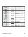
1
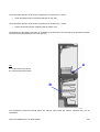
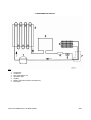
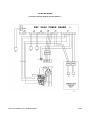
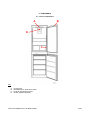
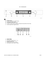
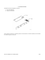
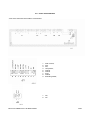
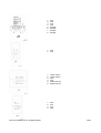
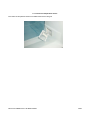
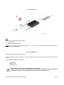
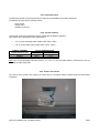
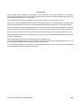
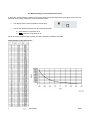
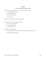
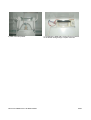
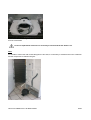
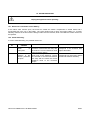
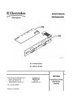
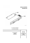
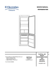
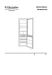
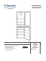
SERVICE MANUAL REFRIGERATION © ELECTROLUX HOME PRODUCTS S.p.A. Spares Operations Italy Corso Lino Zanussi, 30 I - 33080 PORCIA / PN (ITALY) Fax +39 0434 394096 Publication no. 599 37 75-07 060824 ITZ/SERVICE/AA TOTAL NO FROST FIFTY Sliding Door FACTORY: ZS TOTAL NO FROST FIFTY SLIDING DOOR 2/39 CONTENTS 1. INTRODUCTION ..................................................................................................................................................5 2. AIR CIRCULATION..............................................................................................................................................8 3. REFRIGERATION CIRCUIT ................................................................................................................................9 4. ELECTRIC WIRING .......................................................................................................................................... 10 5. COMPONENTS ................................................................................................................................................. 12 5.1. Cooler compartment ................................................................................................................................... 12 5.1.a. Control panel............................................................................................................................................ 13 5.1.b. Electronic boards ..................................................................................................................................... 14 5.1.c. Power board ERF2050............................................................................................................................. 15 5.1.d. Display board ERF2000........................................................................................................................... 17 5.1.e. Air flow regulator (damper) ...................................................................................................................... 18 5.1.f. Cooler air temperature sensor .................................................................................................................. 19 5.2. Freezer compartment.................................................................................................................................. 20 5.2.a. Cold module ............................................................................................................................................. 21 5.2.b. Cold module fan....................................................................................................................................... 21 5.2.c. Defrosting heater...................................................................................................................................... 22 5.2.d. Thermal switches ..................................................................................................................................... 22 5.2.e. Freezer door switch ................................................................................................................................. 22 5.2.f. Freezer air temperature sensor ................................................................................................................ 23 5.2.g. Connection box ........................................................................................................................................ 24 6. OPERATION ..................................................................................................................................................... 25 6.1. Normal......................................................................................................................................................... 25 6.2. Defrosting.................................................................................................................................................... 26 6.3. SUPER Function (rapid freezing)................................................................................................................ 27 6.4. SHOPPING Function (rapid cooling) .......................................................................................................... 27 6.5. Cooler compartment switching off............................................................................................................... 27 6.6. Malfunctioning of cooler temperature sensor.............................................................................................. 28 6.7. Malfunctioning of freezer temperature sensor ............................................................................................ 29 7. ALARMS ........................................................................................................................................................... 30 7.1. Freezer compartment temperature alarm ................................................................................................... 30 8. ACCESSIBILITY TO COOLER COMPARTMENT ........................................................................................... 31 8.1. Air flow regulator (damper) ......................................................................................................................... 31 9. ACCESSIBILITY TO FREEZER COMPARTMENT.......................................................................................... 33 9.1. Battery evaporator ...................................................................................................................................... 33 10. TROUBLESHOOTING .................................................................................................................................... 36 10.1. Excessive ice formation on the battery : ................................................................................................... 36 10.2. Failed defrosting: ...................................................................................................................................... 36 11. SERVICE MODE ............................................................................................................................................. 37 11.1. Starting SERVICE MODE ......................................................................................................................... 37 11.2. Exiting SERVICE MODE........................................................................................................................... 37 11.3. Functions of the SERVICE MODE............................................................................................................ 37 12. DISPLAY SYMBOLS ...................................................................................................................................... 39 TOTAL NO FROST FIFTY SLIDING DOOR 3/39 TOTAL NO FROST FIFTY SLIDING DOOR 4/39 1. INTRODUCTION This manual describes the TOTAL NO FROST refrigerators with Sliding Door system produced in the Susegana factory called ZS. These models feature: - Total No Frost (freezer: no frost; cooler: no frost) Built-in Single-compressor Electronic control (electronic board ERF2050) LCD display (liquid crystal digit) They are appliances (KBIN 260 IT SD) with the following PNCs: PNC 92569770000 92569770100 92569770200 MODEL ERF2620 ERF2620 ZI918/9FFA BRAND Electrolux Electrolux Zanussi The controls of the appliance are inserted in the higher part of the cooler compartment. The power control board is ERF2050. The user interface board is ERF2000 (LCD display) The appliance is a single-compressor one, but it is possible to switch off only the cooler compartment through the temperature regulation knob (position 0). The temperature regulation is the following: from +8 to +2 °C for the cooler from -15 to -24 °C for the freezer The appliance has the following functions: rapid freezing rapid cooling freezer temperature alarm TOTAL NO FROST FIFTY SLIDING DOOR 5/39 The appliance consists of the following compartments: freezer; cooler; The evaporating system consists of: battery cold module (freezer compartment); A Key: A = control panel B = cooler compartment C = cold module D = freezer compartment B C D TOTAL NO FROST FIFTY SLIDING DOOR 6/39 The temperature detection of the cooler compartment is carried out by 1 sensor: cooler temperature sensor (located inside the air vent grid) The temperature detection of the freezer compartment is carried out by 1 sensor: freezer temperature sensor (located inside the freezer cell) The defrosting of the battery evaporator is controlled by the electronic board through the temperature detection of the sensors and the detection of the door opening. A Key: A = cooler temperature sensor B = freezer temperature sensor B The temperature sensors A and B feature the foamed cable inside the cabinet, therefore they are not replaceable. TOTAL NO FROST FIFTY SLIDING DOOR 7/39 2. AIR CIRCULATION Unlike in the PARTIAL NO FROST refrigerator, in the TOTAL type the cooler and the freezer communicate each other, therefore the battery evaporator cools both compartments. The cold produced by the battery evaporator in the freezer compartment is distributed by the F fan placed behind the cold module. Cooler compartment air flow: the cold air is pushed by the fan into the foamed duct and exits from the air flow regulator (damper) E located in the rear part of the diffuser-lamp holder. The air returns in the freezer compartment by means of some foamed ducts entering the air vent grids G. Freezer compartment air flow: the cold air is pushed into the compartment through the air screen and returns into the cold module through the front air vent grid. E G F In case of opening of the freezer or cooler door, the fan stops. To simulate the door closet use a magnet and put it next to the reed element placed on the intermediate crosspiece or to the reed element placed on the electronic board. TOTAL NO FROST FIFTY SLIDING DOOR 8/39 3. REFRIGERATION CIRCUIT Key: 1. 2. 3. 4. 5. 6. 7. compressor; condenser; anti-condensation coil; dehydrator filter; capillary; battery evaporator (freezer compartment); exchanger. TOTAL NO FROST FIFTY SLIDING DOOR 9/39 4. ELECTRIC WIRING ( Check the specific diagram for each model ! ) TOTAL NO FROST FIFTY SLIDING DOOR 10/39 Key: 3. 5. 9. 13. 16. 24. 41. 52. 56. 57. compressor motor protector defrosting heater lamp freezer door switch battery evaporator fan electronic board ERF 2050 air flow regulator (damper) cooler air temperature sensor freezer air temperature sensor a. yellow-green; b. brown; c. blue; d. white; e. black; f. grey; TOTAL NO FROST FIFTY SLIDING DOOR 11/39 5. COMPONENTS 5.1. Cooler compartment B A D C Key: A. B. C. D. control panel reed element for cooler door switch cooler air temperature sensor air flow regulator (damper) TOTAL NO FROST FIFTY SLIDING DOOR 12/39 5.1.a. Control panel Key: A. B. C. D. E. F. ON/OFF button Freezer temperature regulation knob Temperature display button Temperature and function display Function activation button (freezer compartment temperature alarm reset) Cooler temperature regulation knob 1. 2. 3. 4. 5. 6. cooler symbol freezer symbol temperature indicator (sign – or +) temperature indicator SUPER function (rapid freezing) SHOPPING function (rapid cooling) TOTAL NO FROST FIFTY SLIDING DOOR 13/39 5.1.b. Electronic boards The electronic board of the appliance consists of: 1. power board ERF2050 2. display board ERF2000 The two electronic boards are connected by means of a flat cable with a connector; therefore, the two boards are available singularly as spare part. TOTAL NO FROST FIFTY SLIDING DOOR 14/39 5.1.c. Power board ERF2050 - View of the electronic board (side of components): 1. 2. 3. 4. 5. 6. 7. 8. 9. earth contact; free; line; compressor; neutral; neutral; lamp; neutral; defrosting heater; 1. fan; 2. fan. TOTAL NO FROST FIFTY SLIDING DOOR 15/39 1. 2. 3. 4. 5. 6. 7. 8. free; free; free; free; damper; damper; damper; damper. 1. free; 2. free; TOTAL NO FROST FIFTY SLIDING DOOR 1. 2. 3. 4. 5. 6. cooler sensor; cooler sensor; free; free; freezer sensor; freezer sensor; 1. 2. 3. 4. free; free. free; free; 16/39 1. 2. 3. 4. free; free. freezer door switch; freezer door switch; 5.1.d. Display board ERF2000 Key: SW1 SW2 SW3 SW4 LCD POT1 POT2 NTC1 = function activation button (freezer temperature alarm reset); = ON/OFF button; = temperature display button; = reed element; = liquid crystal display; = freezer temperature regulation; = cooler temperature regulation; = room temperature sensor (not used); TOTAL NO FROST FIFTY SLIDING DOOR 17/39 5.1.e. Air flow regulator (damper) The temperature regulation of the cooler compartment occurs by means of the passage or not of cold air from the damper, which can have only 2 fixed positions, opened or closed. The air flow regulator (damper) 1 is located inside the lamp holder diffuser 2. 1 2 The damper consists of a door and a stepping motor and it is connected to the electric wiring by means of a 4pole connector. TOTAL NO FROST FIFTY SLIDING DOOR 18/39 5.1.f. Cooler air temperature sensor The cooler air temperature sensor is located inside the air vent grid. TOTAL NO FROST FIFTY SLIDING DOOR 19/39 5.2. Freezer compartment A B D C Key: A. B. C. D. freezer door switch magnetic sensor freezer door switch reed element freezer temperature sensor (foamed inside the cell) cold module TOTAL NO FROST FIFTY SLIDING DOOR 20/39 5.2.a. Cold module 3 2 1 Key: 1 = cut-out defrosting and safety switches 2 = cold module fan 3 = cold module defrosting heater Note: The cut-out defrosting and safety switches ( +8 / +40 °C ) are connected together, therefore they are not available as single spare parts. 5.2.b. Cold module fan The fan is located behind the cold module. The air is intaken by the fan, therefore, in case of its replacement, ensure that the air is forced towards the cell bottom. The fan has the following characteristics: - power 240 V voltage 3,1 W speed 2000 rpm The fan stops in case of opening of the freezer or cooler door. To simulate the door closed, use a magnet and put it next to the magnetic sensor placed on the intermediate crosspiece or the magnetic sensor placed on the electronic board. TOTAL NO FROST FIFTY SLIDING DOOR 21/39 5.2.c. Defrosting heater The defrosting heater is used to defrost the ice that has accumulated on the battery evaporator. The balancing heater has the following values: - power 274 W voltage 240 V resistance 210 Ohm 5.2.d. Thermal switches The thermal cut-outs are positioned in direct contact with the battery evaporator. They switch off the defrosting heater respectively at: +8 °C cut-out defrosting switch (cable colour: black - blue) +40 °C cut-out safety switch (cable colour: black - white) TYPE OF THERMAL OVERLOAD CUT-OUT DEFROSTING SAFETY CUT-IN TEMPERATURE OPENING CLOSING + 8 °C - 1 °C + 40 °C + 30 °C Note: The cut-out defrosting and safety switch ( +8 / +40 °C ) are connected together, therefore they are not available as single spare parts. 5.2.e. Freezer door switch The control of the freezer door opening is carried out by a magnetic switch located inside the intermediate crosspiece. TOTAL NO FROST FIFTY SLIDING DOOR 22/39 5.2.f. Freezer air temperature sensor The freezer air temperature sensor is foamed inside the cell (see S figure). S TOTAL NO FROST FIFTY SLIDING DOOR 23/39 5.2.g. Connection box The connectors are in the box located inside the freezer: 1. fan (white cables) 2. thermal switches and defrosting heater (cables: brown and blue). 1 TOTAL NO FROST FIFTY SLIDING DOOR 2 24/39 6. OPERATION 6.1. Normal Warning: unplug the appliance before operating. In case of first switching on with a freezer compartment temperature higher then 10 °C, the appliance operates with a test cycle (for the factory) for a maximum time of about 1,5 hours. In this period do not check the correct functioning of the appliance, since the loads are activated only for internal check (compressor, fan, defrosting heater, damper). When the appliance is (OFF) then: the compressor is off the fan is off the is display off Pushing the ON/OFF button, the LCD display switches on with the following displaying: sign + red display background freezer compartment temperature alarm (buzzer active) Push the function activation button to deactivate the buzzer. Regulate the compartment knobs so as to set the following temperatures: about +5 °C in the cooler about -18 °C in the freezer In NO FROST refrigerators, the humidity inside the freezer compartment accumulates on the evaporator battery thanks to the air circulation, thus preventing the formation of frost on food. During normal operation time the electronic board powers the compressor and the fan circuit. The fan and compressor operation is independent (the fan is on only when the compressor is on). The fan is deactivated with a 2 minute delay compared to the compressor. The operation time which corresponds to the interval between the following defrosting lasts about 14 hours with normal opening of the door (it can last up to 72 hours if the doors are never opened!). TOTAL NO FROST FIFTY SLIDING DOOR 25/39 6.2. Defrosting All the humidity in the compartment accumulates on the evaporator, which is the coldest part of the compartment; periodically, about every 14 hours with normal door opening (up to 72 hours if the doors never open!), it is then necessary to defrost the ice on the battery. The defrosting starts after the compressor cut-out or if the compressor is on after 2,5 hours max. The electronic board immediately disconnects the circuit which powers the compressor after 2 minutes the fan, waits 3 minutes and then it powers the circuit of the defrosting heater for a minimum time of about 20 minutes. The heat generated by the defrosting heater does not affect the freezer compartment temperature or the food packages temperature, because the thermal energy is consumed in the defrosting process of the evaporator ice. After 20 minutes, the electronic board checks the state of the thermal switch every minute to detect the cut-out. When the defrosting switch cuts-out, and anyway after 20 minutes, the electronic board switches the compressor on with a 5 minute delay. After 3 minute delay, when the air is already cold, the fan switches on too. If for any reason, the defrosting cut-out switch does not switch on and the battery temperature rises up to 40 °C, the defrosting heater will be switched off by the safety thermal switch. If 1 hour after the starting of the defrosting, the thermal switches did not cut out, the electronic board switches the defrosting heater off and continues its operation. TOTAL NO FROST FIFTY SLIDING DOOR 26/39 6.3. SUPER Function (rapid freezing) The SUPER function (rapid freezing) is activated by pushing the function button till the symbol therefore: appears, the relative symbol SUPER is displayed; the compressor operates in thermostatic conditions and not continuously (as the temperature knob was on max. position) for a duration of about 52 hours, and then it deactivates automatically. To deactivate the SUPER function push the function activation button till the symbol disappears. With the SUPER function the defrosting heater is powered. With the SUPER function some fixed defrosting can anyway occur depending on how much time has elapsed after the last defrosting. 6.4. SHOPPING Function (rapid cooling) The SHOPPING function (rapid cooling) is activated by pushing the function button till the symbol therefore: appears, the relative symbol SHOPPING is displayed; the compressor operates in thermostatic conditions and not continuously (as the temperature knob was on max. position) for a duration of about 6 hours, and then it deactivates automatically. To deactivate the SHOPPING function push the function activation button till the symbol disappears. 6.5. Cooler compartment switching off The refrigerator compartment can be switched off by turning the temperature regulation knob to 0. The display shows OF. The air flow regulator (damper) is closed and the lamp remains off also if the door is open. Note: in order to avoid bad odours inside the cooler, the damper is open and closed immediately at intervals of about 20 minutes. TOTAL NO FROST FIFTY SLIDING DOOR 27/39 6.6. Malfunctioning of cooler temperature sensor If during the normal operation a failure occurs to the cooler NTC temperature sensor (the signal coming from the sensor is out of range), pushing the function activation button: The display shows cooler temperature sensor faulty The air flow regulator (damper) has the following operation: open when the compressor is on closed when the compressor is off When the sensor operates again normally, the above described conditions terminate. Characteristics of the NTC sensor: TOTAL NO FROST FIFTY SLIDING DOOR 28/39 6.7. Malfunctioning of freezer temperature sensor If during the normal operation a failure occurs to the freezer NTC temperature sensor (the signal coming from the sensor is out of range), pushing the function activation button: The display shows freezer temperature sensor faulty The appliance operates with a predefined cycle, therefore the compressor is switched on for 40 minutes and off for 40 minutes alternatively The defrosting procedure is activated every about 14 hours Characteristics of the NTC sensor: TOTAL NO FROST FIFTY SLIDING DOOR 29/39 7. ALARMS 7.1. Freezer compartment temperature alarm When the freezer compartment reaches -11 °C, the temperature alarm activates: The LCD display background is red; The freezer symbol flashes; The temperature digits flash; The buzzer sounds. Push the function activation button to deactivate the buzzer. When normal conditions are reset (after a power failure): The acoustic signal deactivates; The temperature digits flash; The display lighting is red. Pushing the function activation button: The highest temperature reached in the freezer compartment is displayed for 5 minute; The display red lighting switches off. TOTAL NO FROST FIFTY SLIDING DOOR 30/39 8. ACCESSIBILITY TO COOLER COMPARTMENT Warning: unplug the appliance before operating. 8.1. Air flow regulator (damper) To access the air diffuser and its components (air flow regulator and lamp holder) perform the following operations in sequence: a) Remove the lamp cover pushing the hook c) Remove the 2 upper fixing screws TOTAL NO FROST FIFTY SLIDING DOOR b) Remove the filter support pulling it downwards d) Remove the 2 front fixing screws 31/39 e) View of the lamp holder TOTAL NO FROST FIFTY SLIDING DOOR f) The damper is fitted with 2 screws and is connected to the electric wiring through a 4-pole connector 32/39 9. ACCESSIBILITY TO FREEZER COMPARTMENT Warning: unplug the appliance before operating. 9.1. Battery evaporator To access the battery evaporator and its components (fan, defrosting heater, door switch, and thermal switches) perform the following operations in sequence: a) Remove the drawers and the grids b) Remove the 3 screw covers c) Remove the 3 fixing screws of the evaporator shield d) Remove the cover of the connection box e) Detach the 2 connectors of the fan and of the defrosting heater TOTAL NO FROST FIFTY SLIDING DOOR 33/39 f) Release the 3 lower hooks of the air vent grid g) Insert a screwdriver inside the slot h) Insert the edge of the screwdriver and turn it towards the direction of the arrow i) Extract the cold module l) Thermal switch connectors m) Thermal switches Note: The defrosting cut-out and safety thermal switches (+8 / +40°C) are connected together, therefore they are not available as single spare parts. TOTAL NO FROST FIFTY SLIDING DOOR 34/39 n) The fan is fitted to the support which is extracted from the cold module In case of replacement of the fan it is necessary to ensure that the fan draws in air. Note: If to be able to extract the cold module the pipes are too short, it is necessary to release and turn the condenser and the compressor as indicated in figure: TOTAL NO FROST FIFTY SLIDING DOOR 35/39 10. TROUBLESHOOTING WARNING ! Unplug the appliance before operating. 10.1. Excessive ice formation on the battery : If the rubber valve remains open, the humid air outside the freezer compartment is ducted inside and it accumulates too much ice on the battery. The valve remains open if there are foreign bodies or if it looses elasticity; therefore in the first case the foreign bodies must be removed, while in the latter the rubber valve must be replaced. 10.2. Failed defrosting: In case of failed defrosting, the possible causes are: Sequence no. 1 POSSIBLE CAUSES The defrosting heater is interrupted 2 One or both switches of the thermal protectors are open HOW TO CONTROL SOLUTION Unplug the appliance, remove the connector of the heater and verify with the tester the correct resistance value to the connector clamps. Frost the battery, then detach the power plug of the appliance, remove the connector of the thermal switches and verify with the tester the correct resistance value to the connector clamps. If the resistance value does not correspond to the technical data, replace the heater. TOTAL NO FROST FIFTY SLIDING DOOR If the resistance value does not correspond to 0 (zero Ohm) replace the thermal switches assembly. 36/39 11. SERVICE MODE 11.1. Starting SERVICE MODE To start the procedure perform the following operations: 1. 2. 3. 4. 5. Connect the plug to the socket. Switch on the appliance with the ON/OFF button. Open the doors of the appliance. Switch the appliance off with the ON/OFF button. Within the first 10 seconds hold down the two buttons “temperature displaying” and “function activation” simultaneously. The confirmation of the procedure start occurs with the acoustic signalling of the buzzer which emits a long beep and with the lighting up of the LCD display. 11.2. Exiting SERVICE MODE The procedure terminates when one of the following conditions is satisfied: a. The plug is detached from the socket and replugged. b. 40 minutes have elapsed and no button has been pushed. c. The last phase of the procedure has been reached. 11.3. Functions of the SERVICE MODE Press the “displaying temperature” button to skip to the following phase of the procedure. Press the “ON/OFF” button to activate/deactivate the loads (compressor, defrosting heater, lamp, fan and air flow regulator). List of the phases of the SERVICE MODE: 1. All the segments of the display are on. 2. All the segments of the display are off. 3. The number +0 is shown on the display and the load controlled by the ACS TH1 [compressor] is checked. To activate/deactivate the load press the “ON/OFF” button (the load is activated when the SUPER is displayed). function symbol 4. The number +1 is displayed and the load controlled by ACS TH2 [defrosting heater] is checked. To activate/deactivate the load press the “ON/OFF” button (the load is activated when the SUPER is displayed). function symbol 5. The number +2 is shown on the display and the load controlled by the ACS TH3 [lamp] is checked. To activate/deactivate the load press the “ON/OFF” button (the load is activated when the SUPER function symbol is displayed). 6. The number +3 is shown on the display and the load controlled by the ACS TH4 [fan] is checked. To activate/deactivate the load press the “ON/OFF” button (the load is activated when the SUPER function symbol is displayed). 7. The number 00 (= damper closed) or 0F (= damper open) is shown on the display and the air flow regulator (damper) is checked. TOTAL NO FROST FIFTY SLIDING DOOR 37/39 To activate/deactivate the load press the “ON/OFF” button (the load is activated when the SUPER function symbol 8. 9. 10. 11. is displayed). Note: when the procedure skips to the following phase pressing the button “temperature displaying”, the load maintains its status (for example if the compressor had been activated it will remain active also in the following phase. In this way it is possible to check the loads simultaneously. Check of the doors. The display digits correspond to the doors: the unit digits correspond to the cooler door, while the ten digits correspond to the freezer door. If the relative door is closed, the displayed digit is 0 otherwise is 1. Check of the potentiometers. Turning the knobs, the display shows the digits from 00 to 07 (from MIN to MAX position). Check of the counter. The display shows an increasing number at intervals of 1 second. This is a counter used by the board for its internal management. At the same time, the display background changes from red to blue. Check of the temperature sensors. The display shows one of the following codes: code E0 E1 E2 E4 E5 description No error Evaporator sensor faulty Ambient temperature sensor faulty (installed on the display board) Ambient temperature sensor faulty (installed on the power board) 0 degree compartment sensor faulty Note: the error regarding the cooler and freezer air sensors are already displayed during the normal operation. At this point all the phases necessary to check the loads have been displayed, therefore it is advisable to interrupt the SERVICE MODE procedure unplugging and replugging the appliance. Note: if you do not want to interrupt the SERVICE MODE, the procedure continues with some phases dedicated exclusively to the factory, therefore they have not been considered. Also in this case, the exit from the SERVICE MODE is carried out unplugging and replugging the appliance. TOTAL NO FROST FIFTY SLIDING DOOR 38/39 12. DISPLAY SYMBOLS DISPLAY DIGITS DESCRIPTION NOT FLASHING Cooler compartment off (knob on 0) NOT FLASHING It indicates the cooler temperature with normal function [from +2 to +8 °C] NOT FLASHING It indicates the freezer temperature with normal function [from -15 to -24 °C] NOT FLASHING It indicates the cooler temperature with SHOPPING function NOT FLASHING It indicates the freezer temperature with SUPER function FLASHING It indicates the freezer temperature in alarm condition NOT FLASHING It indicates the malfunctioning of the cooler air temperature sensor NOT FLASHING It indicates the malfunctioning of the freezer air temperature sensor NOT FLASHING NOT FLASHING TOTAL NO FROST FIFTY SLIDING DOOR It indicates incompatibility between the electronic boards Solution: check the spare part nos. of the electronic boards It indicates an Eeprom parameter writing/reading error Solution: replace both electronic boards (power and display) 39/39