1
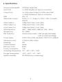
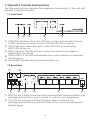
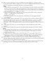
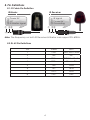
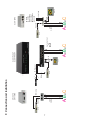
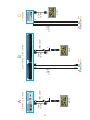
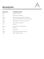
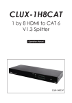
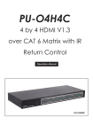
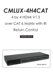
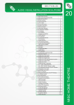
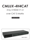
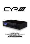
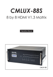
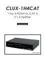
CLUX-1H4CAT 1 by 4 HDMI to CAT 6 V1.3 Splitter Operation Manual CLUX-1H4CAT Disclaimers The information in this manual has been carefully checked and is believed to be accurate. Cypress Technology assumes no responsibility for any infringements of patents or other rights of third parties which may result from its use. Cypress Technology assumes no responsibility for any inaccuracies that may be contained in this document. Cypress also makes no commitment to update or to keep current the information contained in this document. Cypress Technology reserves the right to make improvements to this document and/or product at any time and without notice. Copyright Notice No part of this document may be reproduced, transmitted, transcribed, stored in a retrieval system, or any of its part translated into any language or computer file, in any form or by any means - electronic, mechanical, magnetic, optical, chemical, manual, or otherwise - without express written permission and consent from Cypress Technology. © Copyright 2009 by Cypress Technology. All Rights Reserved. Version 1.0 October 2009 Trademark Acknowledgments All products or service names mentioned in this document may be trademarks of the companies with which they are associated. Safety Precautions Please read all instructions before attempting to unpack or install or operate this equipment, and before connecting the power supply. Please keep the following in mind as you unpack and install this equipment: Always follow basic safety precautions to reduce the risk of fire, electrical shock and injury to persons. To prevent fire or shock hazard, do not expose the unit to rain, moisture or install this product near water. Never spill liquid of any kind on or into this product. Never push an object of any kind into this product through module openings or empty slots, as you may damage parts. Do not attach the power supply cabling to building surfaces. Do not allow anything to rest on the power cabling or allow it to be abused by persons walking on it. To protect the equipment from overheating, do not block the slots and openings in the module housing that provide ventilation. Revision History Version No V1 Date 20091028 Summary of Change Preliminary Release Table of Contents 1. Introduction ……………………..……………………...…........….……. 1 2. Applications …………………..………………….……...................….. 1 3. Package Contents ………………………...........……….................… 1 4. System Requirements ……………..……….........………............……. 1 5. Features …………………………………………......……........…...…… 2 6. Specifications ………………………………...……..........………....…. 3 7. Operation Controls and Functions ……………...……..............…… 7.1 Front Panel .............................................................................. 4 7.2 Rear Panel .…………………………………..…….......…...….… 4 Pin Definitions ……………...……................................................…… 8.1 IR Cable Pin Definition ............................................................ 6 8.2 RJ-45 Pin Definitions ................................................................ 6 9. Connection and Installation ….………………….........…..…..…...... 7 10. Acronyms …...................................................................................... 9 8. 4 6 1. Introduction The 1 by 4 HDMI to CAT6 1.3 splitter when used with CAT6 to HDMI receivers it will allows user to distribute a HDMI over 45 meters through CAT6 cables over 45 mters This solution provides a direct input of one HDMI to a looped output of HDMI and 3 CAT6 outputs – a smart way to link and display a single source to 4 different screens simultaneously. Alternatively, the HDMI output can also be treated as an extender to connect to another HDMI splitter or cascade with other unit in multiple layers. This unit allows user to transmit HDMI signal via CAT6 without compression over long distance. The HDMI to CAT6 splitter also incorporates functions like EDID, System Reset, Deep color and IR systems. 2. Applications Connect to seven HDMI displays, or plug into another CAT6 splitter to reach several more Integrate your home entertainment system Multi-task project presentations Showroom displays Advertising display control System installation control 3. Package Contents 1 by 4 HDMI to CAT6 Splitter 1 x IR Receiver 1 x IR Blaster 5V DC power supply adaptor Operation Manual 4. System Requirements Input device with an HDMI cable Output display device(s) with HDMI cables and or CAT 6 to HDMI receiver with HDMI cable to display. 1 5. Features HDMI 1.3, HDCP1.1 and DVI1.0 compliant Deep color video up to 12bit, 1080p@60Hz Allows users to link up to four displays HDCP keysets allows each output to work independently when connected to a HDMI display Supports both DVI source/display by using HDMI to/from DVI adaptor cable Supports LPCM 7.1CH, Dolby TrueHD, Dolby Digital Plus and DTS-HD Master Audio transmission (32-192kHz Fs sample rate) Supports a wide range of PC and HDTV resolutions from VGA to SXGA (1280 x 1024) and 480i to 1080p. Selects EDID from TV mode or STD mode (this splitter) Deep color setting of 8 bit or 12 bit IR remote control System restore CEC Bypass 2 6. Specifications Frequency Bandwidth 2.25Gbps (single link) Input Ports 1 x HDMI female port (Type A connector) Output Ports 3 x CAT6 output Video/3 x CAT6 output DDC 1 x HDMI female port (Type A connector) EDID STD / TV HDMI Audio Output PCM2, 5.1, 7.1, Dolby 5.1, DTS 5.1, DD+, D-TrueHD, DTS-HD HDMI Cable In 1080p 8-bit (15M), 12-bit (10M) HDMI Cable Out 1080p 8-bit (15M), 12-bit (10M) CAT6 Cable Out 1080p 8-bit (45M), 12-bit (15M) HDMI Resolution 480i, ~ 1080p 50/60, 1080p 24, VGA ~ SXGA IR Frequency 20 ~ 60KHz ESD Protection Human body model: ± 8kV (air-gap discharge) ± 4kV (contact discharge) Power Supply 5VDC/3.2A (US/EU standards, CE/FCC/UL certified) Dimensions (mm) 215(W) x133(D) x 43(H) Weight(g) 900 Chassis Material Metal Silkscreen Color Black Power Consumption 12W Operating Temperature 0˚C ~ 40˚C / 32˚F ~ 104˚F Storage Temperature -20˚C ~ 60˚C / -4˚F ~ 140˚F Relative Humidity 20~90% RH (non-condensing) 3 7. Operation Controls and Functions The following sections describe the hardware components of the unit with installation and functionality. 7.1 Front Panel ① ② ③ ④ ⑤ ① HDMI/DVI indicators: When the LED turns on this means the input source is HDMI and when the input source is DVI the LED will not turn on. ② HDCP indicators: When the input source has HDCP protection the HDCP LED will turn on. ③ SYNC Indicator: The LED will turn on when the input source's signal is detected by the device. ④ Output LED1~4: The LED will illuminate when output display is connected with power on. ⑤ Power LED: The LED will turn on when power is on. 7.2 Rear Panel ① ③ ② ④ ⑤ ⑥ ⑦ ⑧ ① IR IN: This slot is to be connected with the IR receiver cable included in the package and use the source’s remote to control source equipment. ② OUT: This slot connects with the IR blaster cable included in the package and should be placed it in front of the source for sending and infrared signal. 4 ③ EDID Control Switcher: Switch the EDID between STD & TV. Switch to STD to use the built-in EDID or switch to TV to use TV’s EDID. Default factory setting is on TV, leave as is when the display is working properly. Note: 1. When EDID is switched to TV, the unit will detect the first HDMI output EDID and record in the unit. If the first detected output source is DVI it will pass on to the next one until the first HDMI source been detected. The detection priority is HDMI v1.3 > HDMI v1.2 > DVI. 2. When EDID switches to STD the unit will use built-in EDID which supports: Video → 1080p 8-bit or 12-bit (max) Audio → PCM 2CH 3. The EDID selection will only activate when the unit is plugged in and powered on. ④ System Reset: When switched “ON”, the system will send the internal CEC to the display within 8~10 minutes to force all the displays to switch to HDMI 1 input port. Meanwhile, the source’s CEC will not be functioning. When switched “OFF”, the system reset function will be stopped. Factory default is “OFF”. ⑤ HDMI input: This slot is for connecting the source equipment with HDMI cables. ⑥ HDMI output: These slots are for connecting the display with HDMI Cables. Note: A. This system was tested with CAT-6E/23AWG/ cables, so if using cables of another type, the user must be warned that this may result in a lower maximum distance. B. Cable distance tested with a PS3 40G, and 37" Samsung 12 bit LCD TV. C.Figures provided in this manual are reference figures only, actual figures may depend on source and display use with cable specification. ⑦ Video/DDC 2~4: These slots allow you to connect HDMI displays with a CAT6 to HDMI receiver. When more than one output is connected, the HDMI outputs will play an identical video signal. ⑧ Power: This slot is where you plug in the 5VDC power supply included in the package into the unit and connect the adaptor to an AC outlet. 5 8. Pin Definitions 8.1 IR Cable Pin Definition IR Blaster IR Receiver ① Power 5V ② NC ③ IR blaster signal ① IR signal ② Power 5V ③ Grounding ① ②③ ① ②③ Note: The frequency on both IR Receiver & Blaster can support 20~60KHz. 8.2 RJ-45 Pin Definitions Pin Video DDC 1 TX2+ DDC Bus Clock 2 TX2- NC 3 TX1+ DDC Bus Data 4 TX0+ Power 5V 5 TX0- GND 6 TX1- IR IN 7 TXC+ HPD 8 TXC- CEC 6 DVD 7 DDC AorBorC CAT6 OUTPUT IR Blaster DVD IR Blaster IN IR Receiver HDMI HDMI Cable HDMI HD TV VIDEO DDC x3 CAT6 OUTPUT AorBorC OUT CLUX-1H4CAT CLUX-1H8CAT HDMI DVD HDMI Cable DDC AorBorC CAT6 OUTPUT HDMI VIDEO HD TV CAT6 IN CH-106TX CH-1106TX CLUX-1H4CAT CLUX-1H8CAT CMLUX-4H4CAT CLUX-22HC CLUX-22HC HDMI IN HDMI HDMI HDMI IN HDMI CH-106TX CH-1106TX VIDEO 9. Connection and Installation 7M VIDEO 3M DDC 30° HDMI 30° HDMI 3M HDMI HDMI 30° 3M 7M IR Receiver HD TV 30° 3M HDMI HDMI Cable VIDEO AorBorC CAT6 OUTPUT DDC HDMI Cable B HDMI 30° 3M HD TV 30° 3M 7M IR Receiver CLUX-1CAT4H / CLUX-1CAT8H VIDEO AorBorC CAT6 OUTPUT HDMI HD TV HDMI Cable C CLUX-22HC DDC A HDMI CH-106RX / CH-1106RX HDMI 8 Acronyms Acronym Complete Term CAT6 Category 6 cable DVI Digital Visual Interface EDID Extended Display Identification Data HDCP High-Bandwidth Digital Content Protection HDMI High-Definition Multimedia Interface HDTV High-Definition Television IR Infrared LPCM Linear Pulse Code Modulation STD Standard SYNC Synchronize SXGA Super Extended Graphics Array VGA Video Graphics Array A CYPRESS TECHNOLOGY CO., LTD. Home page: http://www.cypress.com.tw 20100401 MPM-CLUX1H4CAT