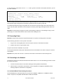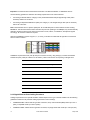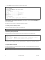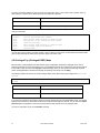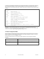
1
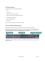
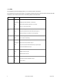
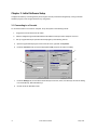
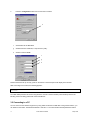
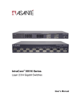
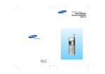
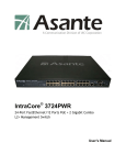
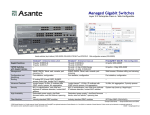
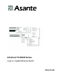
IntraCore® IC36240 Series Layer 2+ Gigabit Ethernet Switch Setup Guide IntraCore IC36240 Layer 2+ Gigabit Ethernet Switch Setup Guide Asante Technologies, Inc. 2223 Oakland Road San Jose, CA 95131 USA SALES 800-662-9686 Home/Office Solutions 800-303-9121 Enterprise Solutions 408-435-8388 TECHNICAL SUPPORT 801-566-8991: Worldwide 801-566-3787: Fax www.asante.com/support [email protected] SWITCH DEFAULTS IP address: 192.168.0.1 Password: Asante Copyright © 2005 Asante Technologies, Inc. All rights reserved. No part of this document, or any associated artwork, product design, or design concept may be copied or reproduced in whole or in part by any means without the express written consent of Asante Technologies, Inc. Asante and IntraCore are registered trademarks and the Asante logo, AsanteCare, Auto-Uplink, and IntraCare are trademarks of Asante Technologies, Inc. All other brand names or product names are trademarks or registered trademarks of their respective holders. All features and specifications are subject to change without prior notice. 05/11/05 2 Asante IntraCore IC36240 Setup Guide Table of Contents Table of Contents...........................................................................................................................................................3 Chapter 1: Introduction...................................................................................................................................................6 1.1 Features ...............................................................................................................................................................6 1.2 Package Contents ................................................................................................................................................7 1.3 Front and Back Panel Descriptions ......................................................................................................................7 1.3.1 LEDs ..............................................................................................................................................................8 1.4 Management and Configuration ...........................................................................................................................9 1.4.1 Console Interface ...........................................................................................................................................9 Chapter 2: Hardware Installation and Setup ................................................................................................................10 2.1 Installation Overview ..........................................................................................................................................10 2.1.1 Safety Overview...........................................................................................................................................10 2.1.2 Recommended Installation Tools .................................................................................................................11 2.1.3 Power Requirements....................................................................................................................................11 2.1.4 Environmental Requirements.......................................................................................................................11 2.1.5 Cooling and Airflow ......................................................................................................................................11 2.2 Installing into an Equipment Rack ......................................................................................................................11 2.2.1 Equipment Rack Guidelines.........................................................................................................................12 2.3 SFP Mini GBIC Ports..........................................................................................................................................12 2.4 Installing the Optional External Power Supply....................................................................................................12 2.5 Connecting Power ..............................................................................................................................................13 2.6 Connecting to the Network .................................................................................................................................13 2.6.1 10/100/1000BaseT Ports Cabling Procedures .............................................................................................13 2.6.2 Gigabit Ethernet Ports Cabling Procedures .................................................................................................14 Chapter 3: Initial Software Setup..................................................................................................................................16 3.1 Connecting to a Console ....................................................................................................................................16 3 Asante IntraCore IC36240 Setup Guide 3.2 Connecting to a PC ............................................................................................................................................17 3.3 Passwords and Privileges Commands ...............................................................................................................18 3.3.1 Privileges Commands ..................................................................................................................................18 3.3.2 Enable Password .........................................................................................................................................18 3.3.3 Password .....................................................................................................................................................19 3.3.4 Service Password-Encryption ......................................................................................................................19 3.4 Login Security.....................................................................................................................................................20 3.4.1 The username Command ............................................................................................................................20 3.4.2 The password and login Commands............................................................................................................20 3.5 Configuring an IP Address..................................................................................................................................20 3.5.1 Setting a Default IP Gateway Address .........................................................................................................21 3.6 Restoring Factory Defaults .................................................................................................................................21 3.7 System Boot Parameters....................................................................................................................................21 Chapter 4: Understanding the Command Line Interface (CLI) .....................................................................................22 4.1 User Top (User EXEC) Mode .............................................................................................................................22 4.2 Privileged Top (Privileged EXEC) Mode.............................................................................................................23 4.3 Global Configuration Mode.................................................................................................................................24 4.3.1 Interface Configuration Mode.......................................................................................................................26 4.3.2 Spanning-Tree Configuration Mode .............................................................................................................26 4.3.3 VLAN Configuration Mode ...........................................................................................................................27 4.4 Advanced Features Supported within the Command Mode ...............................................................................27 4.5 Checking Command Syntax ...............................................................................................................................29 4.6 Using CLI Command History ..............................................................................................................................30 4.7 Using the No and Default Forms of Commands .................................................................................................30 4.8 Using Command-Line Editing Features and Shortcuts.......................................................................................30 4.8.1 Moving Around on the Command Line.........................................................................................................31 4.8.2 Completing a Partial Command Name.........................................................................................................31 4.8.3 Editing Command Lines That Wrap .............................................................................................................32 4.8.4 Deleting Entries............................................................................................................................................33 4 Asante IntraCore IC36240 Setup Guide 4.8.5 Scrolling Down a Line or a Screen ...............................................................................................................33 4.8.6 Redisplaying the Current Command Line ....................................................................................................33 4.8.7 Transposing Mistyped Characters ...............................................................................................................34 4.8.8 Controlling Capitalization .............................................................................................................................34 Appendix A: Basic Troubleshooting .............................................................................................................................35 Appendix B: Specifications...........................................................................................................................................36 B.1 Standards Compliance ...................................................................................................................................37 B.2 Technical Support and Warranty ....................................................................................................................37 Appendix C: FCC Compliance and Warranty Statements............................................................................................38 C.1 FCC Compliance Statement...........................................................................................................................38 C.2 Important Safety Instructions..........................................................................................................................38 C.3 IntraCare Warranty Statement........................................................................................................................39 Appendix D: Online Warranty Registration...................................................................................................................40 Index ............................................................................................................................................................................41 5 Asante IntraCore IC36240 Setup Guide Chapter 1: Introduction The IntraCore IC36240 24-port Layer 2+ Managed Gigabit Switch is a high-performance network switch used to reduce network congestion and application response times. The 24-port IntraCore IC36240 multi-protocol switch supports Layer 2+ and Gigabit Ethernet switching. The switch has 24 10/100/1000BaseT ports with Auto-Uplink and has 4 combination ports used for sharing with SFP mini GBICs. Gigabit fiber technology is used to connect two switches together. The switches also have an SNMP-based management agent embedded on the main board. This agent supports both in-band and out-of-band access for managing the switch. These switches have a broad range of features for Layer 2+ switching delivering reliability and consistent performance for network traffic. The switches improve network performance by segregating them into separate broadcast domains with IEEE 802.1Q compliant VLANs and provide multimedia applications with multicast switching and CoS services. The system can operate as a stand-alone network or be used in combination with other IntraCore switches in the backbone. 1.1 Features The IntraCore IC36240 Gigabit Ethernet switch is a 24-port Layer 2+ multi-media, multi-protocol (Ethernet and Layer 2+) switch. The following is a list of features: • 24 port 10/100/1000 switch with auto-uplink • Supports wire-speed L2+ switching • CoS provisioning on Layers 2 and 802.1p, IP precedence (TOS, DSCP, TCP/UDP) port number • Flexible wire-speed packet classification • Packet filtering • 16K MAC address • 1K configurable port-based support for 4K VLAN ID, IGMP snooping • SNMP v1, v2, and v3, RMON, statistics counters supported • Spanning Tree Protocol 802.1D (standard), 32 instances of 802.1w (rapid) VLAN and 802.1s (multiple) • 12 trunks and 8 ports/trunk link aggregation • 2MB internal packet buffer • Support for Jumbo Frames (up to 9 KB in length) 6 Asante IntraCore IC36240 Setup Guide 1.2 Package Contents The following items are included in the switch’s package: • Switch • AC power cord • USB cable for management console port • RS232 null-modem cable for management console port • Rack mount brackets with screws • IntraCore IC36240 CD-ROM • Release Note Contact your dealer immediately if any of these items is missing. 1.3 Front and Back Panel Descriptions The following section describes the front and back panels of the IntraCore IC36240 Series switches. The front panel of the IntraCore IC36240 contains the following: power and port LEDs, 24 10/100/1000BaseT ports, 4 dual-function Gigabit ports that support either 1000BaseT or mini GBIC Gigabit Ethernet ports, a USB port and a console port. For information on LEDs refer to the following section in this chapter. Ethernet ports Mini GBIC ports USB port RS-232 port The back panel contains a 12 VDC jack for emergency power (optional), the primary power-bay cover plate and the primary power outlet. 7 Asante IntraCore IC36240 Setup Guide 1.3.1 LEDs The IC36240 front panel LED display allows you to monitor the status of the switch. The IC36240 has one power LED indicator, one (optional) external power LED and one fan LED. There are also LED indicators for each of the 24 ports. Refer to the following table for LED information. LED System Color Green Description Power is on and the system is operating normally. Green Flashing Flashing during self-test, initialization, or downloading. External Power Supply Fan Port Status Amber Detects hardware malfunction (temperature, fan or voltage). Off Power is off, or main power has failed. Green External power supply is installed and ready to provide power. Amber Internal power supply has failed and the external power supply is on. Off External power supply is not installed or is not working properly. Green Fans are working properly. Amber One or more fan is malfunctioning. Green An RJ-45 or SFP link is present; the port is enabled. Green Flashing Frames are received or transmitted on the port. Link/Speed Duplex/Activity 8 Amber Link is present; the port has been disabled manually or by spanning tree. Off No link has been established on the port. Green 1000Mbps connection on the port. Amber 100Mbps connection on the port. Off 10Mbps connection on the port. Green A full-duplex link has been established on the port. Amber A half-duplex link has been established on the port. Off No link on the port. Asante IntraCore IC36240 Setup Guide 1.4 Management and Configuration The switch is managed using Command Line Interface (CLI) in order to access several different command modes. Entering a question mark (?) at each command mode’s prompt provides a list of commands. 1.4.1 Console Interface Support for local, out-of-band management is delivered through a terminal or modem attached to the EIA/TIA-232 or USB interface. You can access the switch by connecting a PC or terminal to the console port of the switch, via a serial cable. The default password set on the console line is Asante (it is case-sensitive). The default IP address is 192.168.0.1/24. Remote in-band management is available through Simple Network Management Protocol (SNMP) and Telnet client. When connecting via a Telnet session (line vty0), the default password is also Asante (case-sensitive). See Chapter 2 for more information on connecting to the switch. 9 Asante IntraCore IC36240 Setup Guide Chapter 2: Hardware Installation and Setup Use the following guidelines to easily install the switch, ensuring that it has the proper power supply and environment. 2.1 Installation Overview Follow these steps to install the IntraCore IC36240 switch: 1. Open the box and check the contents. See Chapter 1.2 Package Contents for a complete list of the items included with the IntraCore IC36240 switch. 2. Install the switch in an equipment or wall rack, or prepare it for desktop placement. 3. Connect the power cord to the switch and to an appropriate power source. 4. Connect network devices to the switch. See the sections below for more detailed installation instructions. 2.1.1 Safety Overview The following information provides safety guidelines to ensure your safety and to protect the switch from damage. Note: This information is a guideline, and may not include every possible hazard. Use caution when installing this switch. • Only trained and qualified personnel should be allowed to install or replace this equipment • Always use caution when lifting heavy equipment • Keep the switch clean • Keep tools and components off the floor and away from foot traffic • Avoid wearing rings or chains (or other jewelry) that can get caught in the switch. Metal objects can heat up and cause serious injury to persons and damage to the equipment. • Avoid wearing loose clothing (such as ties or loose sleeves) when working around the switch When working with electricity, follow these guidelines: • Disconnect all external cables before installing or removing the cover • Do not work alone when working with electricity • Always check that the cord has been disconnected from the outlet before performing hardware configuration • Do not tamper with the equipment. Doing so could void the warranty • Examine the work area for potential hazards (such as wet floors or ungrounded cables) 10 Asante IntraCore IC36240 Setup Guide 2.1.2 Recommended Installation Tools You need the following additional tools and equipment to install the switch into an equipment rack: • Flat head screwdriver • Phillips head screwdriver • Antistatic mat or foam 2.1.3 Power Requirements The electrical outlet should be properly grounded, located near the switch and be easily accessible. Make sure the power source adheres to the following guidelines: • Power: Auto Switching AC, 90-240 VAC • Frequency range: 50/60 Hz 2.1.4 Environmental Requirements Install the switch in a clean, dry, dust-free area with adequate air circulation to maintain the following environmental limits: • Operating Temperature: 0° to 40°C (32° to 104°F) • Relative Humidity: 5% to 95% non-condensing Avoid direct sunlight, heat sources, or areas with high levels of electromagnetic interference. Failure to observe these limits may cause damage to the switch and void the warranty. 2.1.5 Cooling and Airflow The IntraCore IC36240 switch uses internal fans for air-cooling. Do not restrict airflow by covering or obstructing air vents on the sides of the switch. 2.2 Installing into an Equipment Rack Important: Before continuing, disconnect all cables from the switch. To mount the switch into an equipment rack: 11 1. Place the switch on a flat, stable surface. 2. Locate a rack-mounting bracket (supplied) and place it over the mounting holes on one side of the switch. 3. Use the screws (supplied) to secure the bracket (with a Phillips screwdriver). 4. Repeat the two previous steps on the other side of the switch. Asante IntraCore IC36240 Setup Guide 5. Place the switch in the equipment rack. 6. Secure the switch by securing its mounting brackets onto the equipment rack with the appropriate screws (supplied). Important: Make sure the switch is supported until all the mounting screws for each bracket are secured to the equipment rack. Failure to do so could cause the switch to fall, which may result in personal injury or damage to the switch. 2.2.1 Equipment Rack Guidelines Use the following guidelines to ensure that the switch will fit safely within the equipment rack: • Size: 17.5 x 12.7 x 1.8 inches (440 x 234 x 45 mm) • Ventilation: Ensure that the rack is installed in a room in which the temperature remains below 104° F (40° C). Be sure that no obstructions, such as other equipment or cables, block airflow to or from the vents of the switch • Clearance: In addition to providing clearance for ventilation, ensure that adequate clearance for servicing the switch from the front exists 2.3 SFP Mini GBIC Ports The GBIC Interface is the industry standard for Gigabit Ethernet Interfaces. The Gigabit SFP module inserts into the Mini GBIC port to create a new Gigabit port. The hot-swapping feature on the IntraCore IC36240 lets you install and replace the SFP transceivers while the system is operating; you do not need to disable the software or shut down the system power. To install the module, do the following: 1. Insert the transceiver with the optical connector facing outward and the slot connector facing down. The module is keyed to help establish the correct position. 2. Slide the SFP transceiver into the slot until it clicks into place. 3. Remove the module’s rubber port cap. 4. Connect the cable to the Gigabit SFP module’s port. Caution: When replacing a SFP transceiver you must always disconnect the network cable before removing a transceiver. 2.4 Installing the Optional External Power Supply The IntraCore IC36240 can be equipped with an optional 12 VDC external power supply (part number 52-10029-00). When installed, the external power supply is in standby mode. Should the primary unit fail, the backup automatically switches. In addition, an SNMP fault notice is sent. 12 Asante IntraCore IC36240 Setup Guide To verify the primary power status, use the Switch# show system command. Under System Information, you see the power unit status. System Information -----------------System up for: 000day(s), 01hr(s), 46min(s), 54sec(s) PROM Image Version/Date: 1.00C/Nov 11 2004 17:03:04 DRAM Size: 64.0MB Flash Size: 8.0MB Config NVRAM Size: 128KB Console Baud Rate: 9600 bps Serial No. : BC120002 Power Unit Status = OK When the primary power fails and the external power supply is activated, the unit should be sent for repair. The external power supply is designed to be a temporary replacement when the primary power fails. To install the optional power supply, simply attach the 12V connector of the power supply to the jack located in the center of the rear panel of the switch. Connect the power cord to the power supply and plug the power cord into an outlet. Important: The external power supply is hot under normal operating conditions. To avoid damage or injury, set the power supply on a heat-resistant surface and use caution when handling the unit. 2.5 Connecting Power Important: Carefully review the power requirements (Chapter 2.1.3) before connecting power to the switch. Use the following procedure to connect power to the switch: 1. Plug one end of the supplied power cord into the power connector on the back of the switch. 2. Plug the other end into a grounded AC outlet. The power LED show the initialization is in process. The front panel LEDs blink and the power LED illuminates when it has initialized. The switch is ready for connection to the network. Important: If the power does not come on, check the next section to ensure that the correct cabling is used. 2.6 Connecting to the Network The switch can connect to an Ethernet network with the switch turned on or off. Use the following procedure to make the network connections: 1. Connect the network devices to the switch, following the cable guidelines outlined below. 2. After the switch is connected to the network, it can be configured for management capabilities (see the following chapters for information on configuration). 2.6.1 10/100/1000BaseT Ports Cabling Procedures The 10/100/1000 ports on the switch allow for the connection of 10BaseT, 100BaseTX, or 1000BaseT network devices. The ports are compatible with IEEE 802.3 and 802.3u standards. 13 Asante IntraCore IC36240 Setup Guide Important: The switch must be located within 100 meters of its attached 10BaseT or 100BaseTX devices. Use the following guidelines to determine the cabling requirements for the network devices: • Connecting to Network Station: Category 5 UTP (Unshielded Twisted-Pair) straight-through cable (100 m maximum) with RJ-45 connectors • Connecting to Repeater/Hub/Switch’s Uplink port: Category 5, UTP straight-through cable (100 m maximum) with RJ-45 connectors Note: These switches have no specific uplink ports. All 10/100/1000 ports on these switches are auto-sensing MDI/MDI-X. This advanced feature means that when the ports are operating at 10/100Mbps, they will automatically determine whether the device at the other end of the link is a hub, switch, or workstation, and adjust its signals accordingly. No crossover cables are required. Although 10/100BaseT requires only pins 1, 2, 3, and 6, you should use cables with all eight wires connected as shown in Table 2-2 below. 1000BaseT requires that all four pairs (8 wires) be connected correctly, using Category 5 or better Unshielded Twisted Pair (UTP) cable (to a distance of 100 meters). Table 2-2 shows the correct pairing of all eight wires. Pin Number Pair Number & Wire Colors 1 2 White / Orange 2 2 Orange / White 3 3 White / Green 4 1 Blue / White 5 1 White / Blue 6 3 Green / White 7 4 White / Brown 8 4 Brown / White 2.6.2 Gigabit Ethernet Ports Cabling Procedures Cabling requirements for the optional hardware modules depend on the type of module installed. Use the following guidelines to determine the particular cabling requirements of the module(s): • 1000BaseSX GBIC: Cables with SC-type fiber connectors; 62.5µ multi-mode fiber (MMF) media up to 275 m (902'), or 50µ MMF media up to 550 m (1805') • 1000BaseLX GBIC: Cables with SC-type fiber connectors; 10µ single-mode fiber media up to 5 km (16,405') 14 Asante IntraCore IC36240 Setup Guide • 1000BaseLH GBIC: Cables with SC-type fiber connectors; 10µ single-mode fiber media up to 20 km (65,617') • 1000BaseLX Long Haul GBIC: Cables with SC-type fiber connectors; 10µ single-mode fiber media up to 100 km (328,100') • 1000BaseLZ GBIC: Cables with SC-type fiber connectors; 10µ single-mode fiber media up to 120 km (393,701') • 1000BaseT: Category 5 or better Unshielded Twisted Pair (UTP) cable up to 100 m (328.1') When attaching a workstation to the switch, a standard straight-through CAT5 cable may be used, even when the workstation is attached via a patch panel. No crossover cable is needed with the MDX/MDI ports. The switch should be kept off the network until proper IP settings have been set. 15 Asante IntraCore IC36240 Setup Guide Chapter 3: Initial Software Setup Configure the switch by connecting directly to it through a console (out-of-band management), running a terminal emulation program, such as HyperTerminal or by using telnet. 3.1 Connecting to a Console To connect the switch to a console or computer, set up the system in the following manner: 1. Plug power cord into the back of the switch. 2. Attach a straight-through serial cable between the RS232 console port and a COM port on the PC. 3. Set up a HyperTerminal (or equivalent terminal program) in the following manner: a. Open the HyperTerminal program, and from its file menu, right-click on Properties. b. Under the Connect To tab, choose the appropriate COM port (such as COM1 or COM2). c d b 16 c. Under the Settings tab, choose Select Terminal keys for Function, Arrow, and Ctrl keys. Be sure the setting is for Terminal keys, NOT Windows keys d. Choose VT100 for Emulation mode. Asante IntraCore IC36240 Setup Guide e. Press the Configuration button from the Connect To window. e f. Set the data rate to 9600 Baud. g. Set data format to 8 data bits, 1 stop bit and no parity. h. Set flow control to NONE. f g h Now that terminal is set up correctly, power on the switch. The boot sequence will display in the terminal. After connecting to the console, the following appears: User Access Verification Password: The initial default password for access using either the console or telnet is Asante (case-sensitive). Refer to the following section for setting passwords on the terminal lines. 3.2 Connecting to a PC You can connect to the switch through a PC by using either an Ethernet or USB cable. Using a telnet session, you can telnet into the switch. The default IP address is 192.168.1.1. The case-sensitive default password is Asante. 17 Asante IntraCore IC36240 Setup Guide 3.3 Passwords and Privileges Commands The switch has not default password, which allows anyone on the network access to various privilege levels. To prevent unauthorized changes to the switch’s configuration, you should set an enable password for access to switch management. Follow the example below to assign a privileged password. Switch> enable Password: <no password by default; press Enter> Switch# configure Switch(config)# enable password ? 0 Specifies an UNENCRYPTED password will follow 7 Specifies a HIDDEN password will follow LINE The UNENCRYPTED (cleartext) 'enable' password Switch(config)# enable password 0 <password> Switch(config)# exit Switch# write [memory file] A separate password should be set for the primary terminal line (console) and the virtual terminal lines (telnet). The default password Asante is assigned only to the virtual terminal line Vty0. Up to three other virtual terminal lines may be created, and they each will require a separate password. 3.3.1 Privileges Commands The following sections describe the password privileges commands used to control access to different levels of the switch: • Enable Password • Password • Service Password-Encryption 3.3.2 Enable Password To set a local password to control access to various privilege levels, use the enable password command in global configuration mode. Use the no form of this command to remove the password requirement. Switch(config)# enable password ? 0 Specifies an UNENCRYPTED password will follow 7 Specifies a HIDDEN password will follow LINE The UNENCRYPTED (cleartext) 'enable' password Switch(config)# enable password 0 <password> Switch(config)# exit Switch# write [memory file] 18 Asante IntraCore IC36240 Setup Guide 3.3.3 Password To specify a password on a line, use the password command in line configuration mode. Use the no form of this command to remove the password. Switch(config)# line ? console Primary terminal line vty Virtual terminal Switch(config)# line console ? <0-0> Line number Switch(config)# line console 0 Switch(config-line)# ? end End current mode and change to enable mode exec-timeout Set timeout value exit Exit current mode and down to previous mode help Description of the interactive help system no Negate a command or set its defaults password Set a password quit Exit current mode and down to previous mode Switch(config-line)# password ? LINE The UNENCRYPTED (cleartext) line password 0 Specifies an UNENCRYPTED line password will follow 7 Specifies a HIDDEN line password will follow Switch(config-line)# password Asante Switch(config-line)# end Switch# write ? file Write to configuration file memory Write configuration to the file (same as write file) terminal Write to terminal Switch# write file Writing current-config to startup-config, Please wait... Configuration saved to startup-config file Switch# 3.3.4 Service Password-Encryption To encrypt passwords, use the service password-encryption command in global configuration mode. Use the no form of this command to restore the default. Refer to section 4.7 “Using the No Form and Default Commands” for more information. Switch(config)# service password-encryption Switch(config)# no service password-encryption Note: You should change the default telnet password to prevent unauthorized access to the switch. The password can be set at unencrypted (level 0) or encrypted (level 7). Switch(config-line)# password ? LINE The UNENCRYPTED (cleartext) line password 0 Specifies an UNENCRYPTED line password will follow 7 Specifies a HIDDEN line password will follow 19 Asante IntraCore IC36240 Setup Guide 3.4 Login Security Two methods are available on the IntraCore IC36240 to configure an authentication query process for better login security: the username command for the global configuration mode and password and login commands from the line configuration mode. 3.4.1 The username Command To establish a username-based authentication system, use the username command in global configuration mode. This method is more effective because authentication is determined on a user basis. The configuration is done for each line. Switch(config)# Switch# username name password password The name argument can be a host name, server name, user ID, or command name. It is restricted to only one word. Blank spaces and quotation marks are not allowed. Optionally, an encrypted password can be used, preceded by a single-digit number that defines what type of encryption is used. Currently defined encryption types are 0 (which means that the text immediately following is not encrypted) and 7 (which means that the text is encrypted using an encryption algorithm). 3.4.2 The password and login Commands Using the password and login commands is less effective because the password is configured for the port, not for the user. Therefore, any user who knows the password can authenticate successfully. This method enables user name and password checking at login time. Authentication is based on the user. Note: The default login user is not set. 3.5 Configuring an IP Address The switch ships with the default IP address 192.168.0.1/24. Connect through the serial port in order to assign the switch an IP address on your network. Follow the steps below to change the switch’s IP address. 1. Connect to the console and press Enter at the Password prompt, as described above. 2. The screen displays the user mode prompt, Switch>. 3. Type enable. The new prompt is Switch#. 4. Type configure. The new prompt is Switch(config)#. 20 Asante IntraCore IC36240 Setup Guide 5. Type ip address and the new address. The following screen appears: Switch> enable Switch# configure Switch(config)# ip address 192.168.123.254/24 Switch(config)# end Switch# show ip Dhcp Client Enabled ..........: No IP Address ...................: 192.108.250.51 Subnet Mask ..................: 255.255.255.0 Default Gateway ..............: 192.108.250.5 HTTP Server ..................: Enabled HTTP Port ....................: 80 Switch# write file Writing current-config to startup-config. Please wait. Configuration saved to startup-config file It is also acceptable to enter the subnet mask by typing ip address 192.168.123.254/24. Use the show interface veth1 command from privileged mode to see the new IP address. The new IP address automatically writes over the default IP address. See Chapter 6 for more information on assigning IP addresses to interfaces. 3.5.1 Setting a Default IP Gateway Address To define the default IP gateway for the switch, insert a static route: Switch(config)# ip default-gateway 192.168.0.254 3.6 Restoring Factory Defaults To restore the switch to its factory default settings, follow the commands shown in the following screen. Switch> enable Switch# reload ? fac-dflt-except-IP factory-default <cr> Reset ALL system parameters except IP parameters to factory default Reset ALL system parameters to factory default The switch is ready for configuration. Refer to the following chapters for management and configuration information. 3.7 System Boot Parameters The IntraCore IC36240 has two boot banks to store its runtime code. You can select which bank to use for the next boot with the following command: Switch(config)# boot system flash {bank1|bank2} 21 Asante IntraCore IC36240 Setup Guide Chapter 4: Understanding the Command Line Interface (CLI) The switch utilizes Command Line Interface (CLI) to provide access to several different command modes. Each command mode provides a group of related commands. After logging into the system, you are automatically in the user top (user EXEC) mode. From the user top mode you can enter into the privileged top (privileged EXEC) mode. From the privileged EXEC level, you can access the global configuration mode and specific configuration modes: interface, Switch, and route-map configuration. Entering a question mark (?) at the system prompt allows you to obtain a list of commands available for each command mode. Almost every Switch configuration command also has a no form. You can use the no form to disable a feature or function. For example, ARP is enabled by default. Specify the command no arp to disable the ARP table. Document Conventions Command descriptions use the following conventions: • Vertical bars ( | ) separate alternative, mutually exclusive, elements • Square brackets ([ ]) indicate optional elements • Braces ({ }) indicate a required choice • Braces within square brackets ([{ }]) indicate a required choice within an optional element • Boldface indicates commands and keywords that are entered literally as shown • Italics indicate arguments for which you supply values Access Each Command Mode The following sections describe how to access each of the CLI command modes: • User Top Mode: Switch> • Privileged Top Mode: Switch# • Global Configuration Mode: Switch(config)# • Interface Configuration Mode: Switch(config-if-IFNAME)# 4.1 User Top (User EXEC) Mode After you log in to the Switch, you are automatically in user top (user EXEC) command mode. The user-level prompt consists of the host name followed by the angle bracket (>): Switch> The default host name is Switch unless it has been changed during initial configuration, using the setup command. The user top commands available at the user level are a subset of those available at the privileged level. In general, the user top commands allow you to connect to remote devices, change terminal settings on a temporary basis, 22 Asante IntraCore IC36240 Setup Guide To list the commands available in user top mode, enter a question mark (?). Use a space and a question mark (?) after entering a command to see all the options for that particular command. Command Purpose ? Lists the user EXEC commands. show ? Lists all the options available for the given command. User top commands: Switch> ? enable exit help ping quit show cls Turn on privileged mode command Exit current mode and down to previous mode Description of the interactive help system Send echo messages Exit current mode and down to previous mode Show running system information Clear screen You may also enter a question mark after a letter or string of letters to view all the commands that start with that letter (with no space between the letter and the question mark). See section 3.8.2. 4.2 Privileged Top (Privileged EXEC) Mode Because many of the privileged commands set the system configuration parameters, privileged access can be password protected to prevent unauthorized use. The privileged command set includes those commands contained in user EXEC mode, as well as the configure command through which you can access the remaining command modes. Privileged EXEC mode also includes high-level testing commands, such as debug. The following example shows how to access privileged EXEC mode. Notice the prompt changes from Switch> to Switch#: Switch> enable Switch# Command Purpose Switch> enable Enters the privileged EXEC mode. Switch# ? Lists privileged EXEC commands. If you have set a password, the system prompts for it before allowing access to privileged EXEC mode. If an enable password has not been set, the enable mode can be accessed only through the console. You can enter the enable password global configuration command to set the password that restricts access to privileged mode. To return to user EXEC mode, use the disable command. 23 Asante IntraCore IC36240 Setup Guide In general, the top (privileged) commands allow you to change terminal settings on a temporary basis, perform basic tests, and list system information. To list the commands available in top mode, enter a question mark (?) at the prompt, as shown in the following example. Enter a question mark (?) after a command to see all the options for that command. Switch> enable Switch# ? clear clock configure copy debug disable erase exit help ip no ping quit reload show snmp-server write cls Reset functions Manage the system clock Enter configuration mode Copy from one file to another Debugging functions Turn off privileged mode command Erase a filesystem Exit current mode and down to previous mode Description of the interactive help system Global IP configuration subcommands Negate a command or set its defaults Send echo messages Exit current mode and down to previous mode Halt and perform a cold restart Show running system information SNMP related functions Write running configuration to memory, network, or terminal Clear screen Important: To retain configuration changes after a system reload you must save changes made in running configuration to the startup configuration file. From the privileged level, configurations can be saved using the write command or by using the copy running-config startup-config command. 4.3 Global Configuration Mode Global configuration commands apply to features that affect the system as a whole, rather than just one protocol or interface. Commands to enable a particular routing function are also global configuration commands. To enter the global configuration mode, use the configure command. The following example shows how to access and exit global configuration mode and list global configuration commands. Command Purpose Switch# configure From privileged EXEC mode, enters global configuration mode. Switch(config)# ? Lists the global configuration commands. 24 Asante IntraCore IC36240 Setup Guide To exit global configuration command mode and return to privileged EXEC mode, use one of the following commands: Command Purpose exit end Exits global configuration mode and returns to privileged EXEC mode. Ctrl-Z To list the commands available in global configuration mode, enter a question mark (?) at the prompt, as shown in the following example. Enter a question mark (?) after a specific command to see all the options for that command. Switch# configure Switch(config)# ? access-list arp banner boot clock define dot1x duplicate-ip enable end exit help hostname interface ip lacp line logging mac mac-address-table monitor no priority-list quit service show snmp-server sntp spanning-tree tos-list username vlan write Add an access list entry Set static arp entry Define a login banner Modify system boot parameters Manage the system clock Create a definition IEEE 802.1x configuration Duplicate IP Address detection Global Commands Modify enable password parameters End current mode and change to enable mode Exit current mode and down to previous mode Description of the interactive help system Set system's network name Select an interface to configure Global IP configuration subcommands Configure LACP Configure a terminal line Message Logging global configuration commands Add a mac access list entry MAC Address Table global configuration command Traffic Monitoring Global configuration commands Negate a command or set its defaults Priority List global configuration commands Exit current mode and down to previous mode Modify use of network based services Show running system information Modify SNMP parameters Modify SNTP parameters Spanning Tree Protocol global command Tos List global configuration commands To establish a username-based authentication system VLAN global configuration command Write running configuration to memory, network, or terminal From global configuration mode, you can access three additional configuration modes: Use the interface, spanningtree, and vlan commands to access their respective configuration modes. 25 Asante IntraCore IC36240 Setup Guide 4.3.1 Interface Configuration Mode Many features are enabled on a per-interface basis. Interface configuration commands modify the operation of an interface such as an Ethernet or serial port. Interface configuration commands always follow an interface global configuration command, which defines the interface type as Ethernet. In the following example shows configuration of Ethernet interface (eth1). The new prompt, Switch(config-ifeth1)#, indicates the interface configuration mode. In this example, the user asks for help by requesting a list of commands. Switch(config)# interface eth1 Switch(config-if-eth1)# ? description Interface specific description dot1x IEEE 802.1x configuration duplex Configure duplex operation end End current mode and change to enable mode exit Exit current mode and down to previous mode fair-queue Fair-queue interface configuration commands flow-control IEEE 802.3X Flow Control Enable command help Description of the interactive help system ip Interface Internet Protocol config commands lacp Configure LACP mac control access to an interface mtu Set the interface Maximum Transmission Unit (MTU) negotiation Select Autonegotiation mode no Negate a command or set its defaults priority-group Assign a priority queue list to an interface quit Exit current mode and down to previous mode rate-limit To configure committed access rate (CAR)policies show Show running system information shutdown Shutdown the selected interface spanning-tree Spanning Tree Protocol interface command speed Configure speed operation storm-control Enable storm control on the interface. switchport Port operating in L2 mode tos-group Assign a tos list to an interface traffic-shape Generic traffic shape QoS interface configuration commands write Write running configuration to memory, network, or terminal To exit interface configuration mode and return to global configuration mode, enter the exit command. To exit configuration mode and return to top mode, use the end command or press Ctrl-Z. 4.3.2 Spanning-Tree Configuration Mode Spanning Tree configuration commands are used to configure an IP routing protocol and always follow a Switch command. To list the available Switch configuration keywords, enter the Switch command followed by a space and a question mark (?) at the global configuration prompt. Switch(config)# mst forward-time hello-time max-age priority rapid 26 spanning-tree ? Enable multiple spanning tree (IEEE 802.1s) Set forwarding delay time Set interval between HELLOs Maximum allowed message age of received Hello BPDUs Set bridge priority Enable rapid convergence Asante IntraCore IC36240 Setup Guide In the following example, the switch shows the multiple Spanning Trees (MST) command. Switch(config)# spanning-tree mst configuration Switch(config-mst)# ? end End current mode and change to enable mode exit Exit current mode and down to previous mode help Description of the interactive help system instance MST instance name Set MST configuration name no Negate a command or set its defaults quit Exit current mode and down to previous mode revision Set MST configuration revision number show Show running system information write Write running configuration to memory, network, or terminal To exit Spanning Tree configuration mode and return to global configuration mode, enter the exit command. To exit configuration mode and return to top mode, use the end command or press Ctrl-Z. 4.3.3 VLAN Configuration Mode Use the VLAN configuration mode to partition a single IntraCore IC36240 into a VLAN each containing it own set of ports. To access and list the VLAN configuration commands, use the command in global configuration mode. In the following example, a VLAN named myvlan is configured. Enter a question mark (?) to list vlan configuration commands. Switch(config)# vlan name myvlan Switch(config-vlan)# ? end End current mode and change to enable mode exit Exit current mode and down to previous mode help Description of the interactive help system name Specify VLAN Name port-member VLAN port member configuration quit Exit current mode and down to previous mode show Show running system information write Write running configuration to memory, network, or terminal To exit VLAN configuration mode and return to global configuration mode, enter the exit command. To exit configuration mode and return to top mode, use the end command or press Ctrl-Z. 4.4 Advanced Features Supported within the Command Mode Enter a question mark (?) at the system prompt to display a list of commands available for each command mode. You can also get a list of any command's associated keywords and arguments with the context-sensitive help feature. 27 Asante IntraCore IC36240 Setup Guide To get help specific to a command mode, a command, a keyword, or an argument, perform one of the following commands: Command Purpose Help Obtain a brief description of the help system in any command mode. ? List all commands available for a particular command mode. When using context-sensitive help, the space (or lack of a space) before the question mark (?) is significant. To obtain a list of commands that begin with a particular character sequence, type in those characters followed immediately by the question mark (?). Do not include a space. This form of help is word help, because it completes a word for you. To list keywords or arguments, enter a question mark (?) in place of a keyword or argument. Include a space before the question mark (?). This form of help is command syntax help, because it reminds you which keywords or arguments are applicable based on the command, keywords, and arguments you already have entered. You can abbreviate commands and keywords to the number of characters that allow a unique abbreviation. For example, you can abbreviate the configure command to config. Because the shortened form of the command is unique, the switch accepts the shorted form and executes the command. Enter the help command (which is available in any command mode) for a brief description of the help system: Switch# help CLI/VTY provides advanced help feature. When you need help, anytime at the command line please press '?'. If nothing matches, the help list will be empty and you must backup until entering a '?' shows the available options. Two styles of help are provided: 1. Full help is available when you are ready to enter a command argument (e.g. 'show ?') and describes each possible argument. 2. Partial help is provided when an abbreviated argument is entered and you want to know what arguments match the input (e.g. 'show cl?'.) Switch# show cl? clock Display the system clock Switch# show cl As described in the help command output, you can enter a partial command name and a question mark (?) to obtain a list of commands beginning with a particular character set. Example of Context Sensitive Help The following example illustrates how the context-sensitive help feature creates an access list from the configuration mode. Enter the letters “co” at the system prompt followed by a question mark (?). Do not leave a space between the last letter and the question mark (?). The system provides the commands that begin with co. Switch# co? configure copy Switch# co Enter configuration mode Copy from one file to another Enter the configure command followed by a space and a question mark (?) to list the command’s keyword(s) and a brief explanation: 28 Asante IntraCore IC36240 Setup Guide Switch# configure ? configure Enter configuration mode Note that in the example below, if you enter the ip command followed by the Return Key or Enter, the system returns the prompt that the command is incomplete. Switch# ip % Command incomplete. Switch# Generally, uppercase letters represent variables. For example, after entering a command, such as hostname, and using a space and a question mark, you will be prompted for the new name, represented by WORD. In cases where an IP address is the variable, the uppercase letters A.B.C.D will represent it. Switch(config)# hostname ? WORD This system's network name In the following access list example, two further options are listed after the question mark. You may enter an optional source wildcard. The return symbol (<cr>) indicates a return key is needed to enter the command. Switch(config)# access-list 99 deny 192.168.123.0 ? A.B.C.D Source wildcard. e.g. 0.0.0.255 <cr> Switch(config)# access-list 99 deny 192.168.123.0 4.5 Checking Command Syntax The CLI user interface provides an error indicator, a caret symbol (^). The caret symbol appears at the point in the command string where you have entered an incorrect letter, command, keyword, or argument. In the following example, suppose you want to add an access-list entry: Switch(config)# access-list ^ % Invalid input detected at '^' marker. In the following example, an incomplete command is entered. Switch(config)# access-list % Command incomplete. Switch(config)# 29 Asante IntraCore IC36240 Setup Guide 4.6 Using CLI Command History The CLI user interface provides a history or record of commands that you have entered. This feature is particularly useful for recalling long or complex commands or entries, including access lists. To recall commands from the history buffer, use one of the following commands: Keystrokes/Command Purpose Press Ctrl-P or the up arrow key Recall commands in the history buffer, beginning with the most recent command. Repeat the key sequence to recall successively older commands. Press Ctrl-N or the down arrow key Return to more recent commands in the history buffer after recalling commands with Ctrl-P or the up arrow key. Repeat the key sequence to recall successively more recent commands. show history While in EXEC mode, list the last several commands entered. 4.7 Using the No and Default Forms of Commands Almost every Switch configuration command has an opposite no form that negates or reverses a command. In general, the no form is used to disable a function that has been enabled. To re-enable a disabled function, or to enable a function that is disabled by default, use the command without the no keyword. For example, Address Resolution Protocol (ARP) is enabled by default. Specify the command no arp to disable the ARP table; to re-enable the ARP table, use the arp command. 4.8 Using Command-Line Editing Features and Shortcuts A variety of shortcuts and editing features are enabled for the CLI command-line interface. The following subsections describe these features: • Moving Around on the Command Line • Completing a Partial Command Name • Editing Command Lines that Wrap • Deleting Entries • Scrolling Down a Line or a Screen • Redisplaying the Current Command Line • Transposing Mistyped Characters • Controlling Capitalization 30 Asante IntraCore IC36240 Setup Guide 4.8.1 Moving Around on the Command Line Use the following keystrokes to move the cursor around on the command line in order to make corrections or changes: Keystrokes Purpose Press Ctrl-B or the left arrow. Move the cursor back one character. Press Ctrl-F or the right arrow. Move the cursor forward one character. Press Ctrl-A. Move the cursor to the beginning of the command line. Press Ctrl-E. Move the cursor to the end of the command line. Press Esc B. Move the cursor back one word. Press Esc F. Move the cursor forward one word. Note: The arrow keys function only on ANSI-compatible terminals such as VT100s. 4.8.2 Completing a Partial Command Name If you cannot remember a complete command name, press the Tab key to allow the system to complete a partial entry. Keystrokes Purpose Enter the first few letters and press Tab. Complete a command name. If your keyboard does not have a Tab key, press Ctrl-I instead. In the following example, when you enter the letters “conf” and press the Tab key, the system provides the complete command: Switch# conf<Tab> Switch# configure The command is not immediately executed, so that you may modify the command if necessary. If you enter a set of characters that could indicate more than one command, the system simply lists all possible commands. You may also enter a question mark (?) to obtain a list of commands that begin with that set of characters. Do not leave a space between the last letter entered and the question mark (?). For example, three commands in privileged mode start with co. To see what they are, type co? at the privileged EXEC prompt: Switch# co? configure copy Switch# co 31 Asante IntraCore IC36240 Setup Guide 4.8.3 Editing Command Lines That Wrap The enhanced editing feature provides a wraparound for commands that extend beyond a single line on the screen. When the cursor reaches the right margin, the command line shifts eight spaces to the left. You cannot see the first eight characters of the line, but you can scroll back and check the syntax at the beginning of the command. To scroll back, use the following command: Keystrokes Purpose Press Ctrl-B or the left arrow repeatedly until you scroll back to the beginning of the command entry, or press Ctrl-A to return directly to the beginning of the line. Return to the beginning of a command line to verify that you have correctly entered a lengthy command. Note: The arrow keys function only on ANSI-compatible terminals such as VT100. In the following example, the access-list command entry extends beyond one line. When the cursor first reaches the end of the line, the line is shifted eight spaces to the left and redisplayed. The dollar sign ($) indicates that the line has been scrolled to the left. Each time the cursor reaches the end of the line, it is again shifted eight spaces to the left. Switch(config)# access-list 101 permit icmp 192.168.123.0 0.0.0.255 192 Switch(config)# $ st 101 permit icmp 192.168.123.0 0.0.0.255 192.168.0.1 32 Asante IntraCore IC36240 Setup Guide When you have completed the entry, press Ctrl-A to check the complete syntax before pressing Enter to execute the command. The dollar sign ($) appears at the end of the line to indicate that the line has been scrolled to the right: Switch(config)# access-list 101 permit icmp 192.168.123.0 0.0.0.255 192$ Use line wrapping in conjunction with the command history feature to recall and modify previous complex command entries. 4.8.4 Deleting Entries Use any of the following commands to delete command entries if you make a mistake or change your mind: Keystrokes Purpose Press Delete or Backspace. Erase the character to the left of the cursor. Press Ctrl-D. Delete the character at the cursor. Press Ctrl-K. Delete all characters from the cursor to the end of the command line. Press Ctrl-U or Ctrl-X. Delete all characters from the cursor to the beginning of the command line. Press Ctrl-W. Delete the word to the left of the cursor. Press Esc D. Delete from the cursor to the end of the word. 4.8.5 Scrolling Down a Line or a Screen When using a command that list more information than will fill on the screen, the prompt --More-- is displayed at the bottom of the screen. Whenever the More prompt is displayed, use the following keystrokes to view the next line or screen: Keystrokes Purpose Press Return. Scroll down one line. Press Spacebar. Scroll down one screen. 4.8.6 Redisplaying the Current Command Line If you are entering a command and the system suddenly sends a message to your screen, you can easily recall your current command line entry. To do so, use the following command: Keystrokes Purpose Press Ctrl-L or Ctrl-R. Redisplay the current command line. 33 Asante IntraCore IC36240 Setup Guide 4.8.7 Transposing Mistyped Characters If you have mistyped a command entry, you can transpose the mistyped characters by using the following command: Keystrokes Purpose Press Ctrl-T. Transpose the character to the left of the cursor with the character located at the cursor. 4.8.8 Controlling Capitalization You can toggle between uppercase and lowercase letters with simple keystroke sequences. To do so, use the following command: Keystrokes Purpose Press Esc C. Capitalize at the cursor. Press Esc C or Alt-C again to return to lowercase letters. 34 Asante IntraCore IC36240 Setup Guide Appendix A: Basic Troubleshooting In the unlikely event that the switch does not operate properly, follow the troubleshooting tips below. If more help is needed, contact Asante’s technical support at www.asante.com/support. Problem Possible Solutions The Power LED is not lit. Check the power connection. Plug the power cord into another known working AC outlet. The primary power supply has failed. Install the optional external power supply and have the primary power supply serviced as soon as possible. The System LED is amber. The switch detects a hardware malfunction. Check the temperature of the room, listen for the fan or the electrical connection. The External Power LED is not lit. The external power supply is not installed properly or has failed. Contact Asante immediately for a replacement. The 10/100/1000 port Link LEDs are not lit. Check the cable connections. Make sure the connectors are seated correctly in each port, and that the correct type of cable is used in each port. See Chapter 2.6: Connecting to the Network for more information. The GBIC Link LED is not lit. Check the GBIC connector. Make sure the cables are inserted correctly, with the Transmit (Tx) connector on one side of the link connected to the Receive (Rx) connector on the other side of the link. Cannot establish communication to another device (switch, router, workstation, etc.). • Make sure the Link LED for the port in use is on. Make sure the correct cable type is used. See Chapter 2.6 Connecting to the Network for more information on cabling procedures • Make sure the IP address, subnet mask, and VLAN membership of the switch are correct • Make sure the switch port and the device are both in the same VLAN • Try to connect to a different port Cannot auto-negotiate the port speed. 35 Make sure that auto-negotiation is supported and enabled on both sides of the link (in both devices). Asante IntraCore IC36240 Setup Guide Appendix B: Specifications The sections below list the features and product specifications for the IntraCore IC36240 switch. Connectors: 24 RJ-45 auto-MDI/MDIX Ports 24 10/100/1000BaseT ports that have auto-negotiation for speed, duplex mode and flow control Gig Modular Ports 4 SFP slots for 1000SX or 1000LX transceiver that is auto-disabling 1000BaseT port when link is activated. Switch ASIC StrataXGS BCM5697 Gigabit PHY 5 x BCM5464R, 1 x BCM5464SR Quad Management CPU 266 Mhz Motorola MPC8245 Console: Serial (RS-232): DB9, USB Status Indicators: Separate link-activity, speed (10/100/Gigabit) and duplex (full or half) LEDs for each port; system power, external power supply and fan. Physical Characteristics Dimensions: Size: 17.5 x 12.7 x 1.7 inches (440 x 322 x 45 mm); 1 RU height Mounting: Install into a standard 19" rack or place on a desktop; rackmount kit included. Environmental Range Operating Temperature: 32º to 104ºF (0º to 40ºC) Relative Humidity: 5% to 95% non-condensing Power: Auto-switching, 90-240 VAC, 50/60 Hz; grounded IEC cord External Power Supply: 12 VDC Auto-switching from main 90/240 VAC for emergency backup Performance Frames 9 KB Jumbo frames, 12 Gbps interconnect, non-blocking MAC addresses 16 K entries Memory 64 MB SDRAM, 2 MB embedded packet bugger VLANs 1k configurable port-based or mac-based, 4k VLAN ID, Private VLAN, IGMP snooping Priority Queues 8 levels IEEE 802.1p Spanning Tree 256 spanning tree group (IEEE 802.1D), fast forwarding proprietary (IEEE 802.1p), rapid spanning tree (IEEE802.1w), 32 instances of per VLAN (IEEE 802.1s) Link Aggregation 12 trunks x 8 ports/trunk, IEEE 802.3ad, Cisco EtherChannel Bandwidth Management IEEE 802.1p COS, TOS, DSCP, TCP/UDP port number 36 Asante IntraCore IC36240 Setup Guide Security User password, SNMP access filter, port security (MAC address filter with notification), 802.1x (port-based, L2/L4 ACL, RADIUS, TACACS+ Management Male DB9 RS-232 DTE (auto baud to 115k), USB, Cisco CLI x 4 sessions, Web RMON (1, 2, 3, 9), port mirroring Firmware Upgrade TFTP, dual banks of code and configuration SNMP v1, v2, v3 Logs System, Crash, Error B.1 Standards Compliance IEEEE: IEEE 802.1D spanning tree and bridge filters IEEE 802.1p prioritization (class of service) IEEE 802.1Q virtual LAN (VLAN) IEEE 802.1s VLAN per spanning tree IEEE 802.1w rapid reconfiguration spanning tree IEEE 802.1x port based L2/L4 ACL, RADIUS, TACACS+ IEEE 802.3x full duplex and flow control IEEE 802.3z 1000BaseSX over 50µ multi-mode fiber; max. 1,804' (550 m) IEEE 802.3ab 1000BaseT over Category 5 UTP (4 pairs); max. 328' (100 m) IEEE 802.3u 100BaseTX over Category 5 UTP (2 pairs); max. 328' (100 m) IEEE 802.3 10BaseT over Category 3 UTP (2 pairs); max. 328' (100 m) IETF: RFC 1155 SMI RFC 1157 SNMP RFC 1212, 1213, 1215 MIB II and Traps RFC 1493 Bridge MIB RFC 1724 RIPv2 MIB RFC 1757 RMON 4 Groups (Statistics, History, Alarms, and Events) RFC 2096 IP-FORWARD-MIB RFC 2674 Bridge Extensions Asante Private MIB Safety: UL 1950, cUL, TUV/GS Emissions: FCC Class A, CE B.2 Technical Support and Warranty IntraCare™: Free technical support and advanced warranty support for 3 years. Includes free telephone support, 24-hour support via web and ftp, complete product warranty with second business day (within the United States) advanced replacement, and software maintenance agreement. ™ AsanteCare : Optional extended technical support and product warranty for 1–2 additional years. See Appendix C: FCC Compliance and Warranty Statements for more detailed information. 37 Asante IntraCore IC36240 Setup Guide Appendix C: FCC Compliance and Warranty Statements C.1 FCC Compliance Statement This equipment has been tested and found to comply with the limits for a Class A digital device, pursuant to part 15 of the FCC Rules. These limits are designed to provide reasonable protection against harmful interference when the equipment is operated in a commercial environment. This equipment generates, uses, and can radiate radio frequency energy and, if not installed and used in accordance with the instruction manual, may cause harmful interference to radio communications. Operation of this equipment in a residential area is likely to cause harmful interference, in which case you will be required to correct the interference at your own expense. C.2 Important Safety Instructions Caution: Do not use an RJ-11 (telephone) cable to connect network equipment. 1. Read all of these instructions. 2. Save these instructions for later use. 3. Follow all warnings and instructions marked on the product. 4. Unplug this product from the wall outlet before cleaning. Do not use liquid cleaners or aerosol cleaners. Use a damp cloth for cleaning. 5. Do not use this product near water. 6. Do not place this product on an unstable cart or stand. The product may fall, causing serious damage to the product. 7. The air vent should never be blocked (such as by placing the product on a bed, sofa or rug). This product should never be placed near or over a radiator or heat register. This product should not be placed in a built-in installation unless proper ventilation is provided. 8. This product should be operated from the type of power source indicated on the marking label. If you are not sure of the type of power available, consult your dealer or local power company. 9. This product is equipped with a three-wire grounding type plug, which is a plug having a third (grounding) pin. This plug will only fit into a grounding type power outlet. This is a safety feature. If you are unable to insert the plug into the outlet, contact your electrician to replace your outlet. Do not defeat the purpose of the grounding type plug. 10. Do not allow anything to rest on the power cord. Do not place this product where people will walk on the cord. 11. If an extension cord is used with this product, make sure that the total ampere ratings on the products into the extension cord do not exceed the extension cord ampere rating. Also make sure that the total of all products plugged into the wall outlet does not exceed 15 amperes. 12. Never push objects of any kind into this product through air ventilation slots as they may touch dangerous voltage points or short out parts that could result in a risk of fire or electric shock. Never spill liquid of any kind on the product. 13. Do not attempt to service this product yourself, as opening or removing covers may expose you to dangerous voltage points or other risks. Refer all servicing to service personnel. 38 Asante IntraCore IC36240 Setup Guide C.3 IntraCare Warranty Statement Products: IntraCore IC36240 Duration: 3 years Advanced Warranty United States: Second Business Day Replacement: Other countries: See your local distributor or reseller 1. Asante Technologies warrants (to the original end-user purchaser) the covered IntraCore products against defects in materials and workmanship for the period specified above. If Asante receives notice of such defects during the warranty period, Asante will, at its option, either repair or replace products that prove to be defective. Replacement products may be either new or like-new. 2. Asante warrants that Asante software will not fail to execute its programming instructions, for the period specified previously, due to defects in material and workmanship when properly installed and used. If Asante receives notice of such defects during the warranty period, Asante will replace software media that does not execute its programming instructions due to such defects. 3. Asante does not warrant that the operation of Asante products will be uninterrupted or error free. If Asante is unable, within a reasonable time, to repair or replace any product to a condition as warranted, customer would be entitled to a refund of the pro-rated purchase price upon prompt return of the product. 4. Asante products may contain remanufactured parts equivalent to new in performance. 5. The warranty period begins on the date of delivery or on the date of installation if installed by Asante. 6. Warranty does not apply to defects resulting from (a) improper or inadequate maintenance or calibration, (b) software, interfacing, parts, or supplies not received from Asante, (c) unauthorized modification or misuse, (d) operation outside of the published environmental specifications for the product, or (e) improper site preparation or maintenance. This warranty expressly excludes problems arising from compatibility with other vendors’ products, or future compatibility due to third-party software or driver updates. 7. TO THE EXTENT ALLOWED BY LOCAL LAW, THE PREVIOUS WARRANTIES ARE EXCLUSIVE AND NO OTHER WARRANTY OR CONDITION, WHETHER WRITTEN OR ORAL, IS EXPRESSED OR IMPLIED AND ASANTE SPECIFICALLY DISCLAIMS ANY IMPLIED WARRANTIES OR CONDITIONS OF MERCHANTABILITY, SATISFACTORY QUALITY, AND FITNESS FOR A PARTICULAR PURPOSE. 8. Asante will be liable for damage to tangible property per incident up to the greater of $10,000 or the actual amount paid for the product that is the subject of the claim, and for damages for bodily injury or death, to the extent that all such damages are determined by a court of competent jurisdiction to have been directly caused by a defective Asante product. 9. TO THE EXTENT ALLOWED BY LOCAL LAW, THE REMEDIES IN THIS WARRANTY STATEMENT ARE THE CUSTOMER’S SOLE AND EXCLUSIVE REMEDIES. EXCEPT AS INDICATED PREVIOUSLY, IN NO EVENT WILL ASANTE OR ITS SUPPLIERS BE LIABLE FOR LOSS OF DATA OR FOR DIRECT, SPECIAL, INCIDENTAL, CONSEQUENTIAL (INCLUDING LOST PROFIT OR DATA), OR OTHER DAMAGE, WHETHER BASED IN CONTRACT, OR OTHERWISE. Some jurisdictions do not allow the exclusion or limitation of incidental or consequential damages or imitations on how long an implied warranty lasts, so the previous limitations or exclusions may not apply to you. This warranty gives you specific legal rights, and you may have other rights, which vary from jurisdiction to jurisdiction. 39 Asante IntraCore IC36240 Setup Guide Appendix D: Online Warranty Registration Please register this product online at http://www.asante.com/support/supRegistration.asp or by filling out and mailing the card below. 40 Asante IntraCore IC36240 Setup Guide Index Cabling interface................................................................26 console .................................................................16 no .........................................................................30 Ethernet ................................................................14 password ..............................................................18 procedures............................................................13 password-encryption ............................................19 CLI show system.........................................................13 advanced features ................................................27 spanning-tree........................................................26 capitalization.........................................................34 username .............................................................20 completing a partial command..............................31 Configuring deleting entries .....................................................33 Ethernet ................................................................26 global configuration mode ....................................24 interface................................................................26 history...................................................................30 spanning-tree........................................................26 interface configuration mode ................................26 VLAN ....................................................................27 lines that wrap ......................................................32 Connecting moving around......................................................31 console .............................................................9, 16 privileged top mode ..............................................23 network .................................................................13 redisplaying current line........................................33 PC ........................................................................17 scrolling ................................................................33 power....................................................................13 shortcuts ...............................................................30 Console top user mode.......................................................22 baud rate ..............................................................17 transposing characters .........................................34 interface..................................................................9 understanding.......................................................22 Default VLAN ....................................................................27 IP address ............................................................20 Command 41 IP gateway............................................................21 checking syntax ....................................................29 password ................................................................9 configuration .........................................................24 restoring ...............................................................21 ethernet interface..................................................26 Description .................................................................7 help.......................................................................28 back panel ..............................................................7 history...................................................................30 front panel ..............................................................7 Asante IntraCore IC36240 Setup Guide Features .....................................................................6 Password editing...................................................................30 default.....................................................................9 Help privileged ..............................................................18 ? 28 security .................................................................20 context sensitive ...................................................28 setting...................................................................18 Installation Requirements emergency power supply......................................12 airflow ...................................................................11 hardware ..............................................................10 environment..........................................................11 into rack ................................................................11 power....................................................................11 mini GBIC .............................................................12 tools......................................................................11 LED Safety activity ....................................................................8 emergency power ...................................................8 42 guidelines .............................................................10 Security link/speed ...............................................................8 login......................................................................20 power......................................................................8 Troubleshooting .......................................................35 Asante IntraCore IC36240 Setup Guide