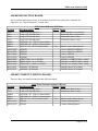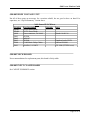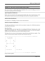
1
The Evil, Infamous, Unreliable, Flaming... Electrohome _______ \ ___ | | |__| | ___ | |_ | |___| | | \_______/ ________ / | | | | | | / | | | | | | ________ \ / ____ | | | | | | |____| | | | | | | \________/ | | \ ____ |____| | | \ / / ____ \ | |____| | | | \________/ Vector Monitor Guide Version 1.14 April 9th, 2012 Table of Contents INTRODUCTION...........................................................................................................3 MONITOR HISTORY....................................................................................................4 PART DESCRIPTIONS..................................................................................................6 HOW IT ALL WORKS.................................................................................................15 REPAIR PREPARATION.............................................................................................16 DEBUGGING THE MONITOR...................................................................................20 INSTALLING A CAP KIT...........................................................................................26 MAKING THE MONITOR MORE RELIABLE..........................................................31 TUBE REPLACEMENT...............................................................................................33 USING A G08-003 WITH COSMIC CHASM.............................................................34 Appendix A: Common Ground Connections................................................................36 Appendix B: Testing Transistors...................................................................................37 Appendix C: Parts Lists.................................................................................................39 REFERENCES..............................................................................................................41 DOCUMENT HISTORY..............................................................................................41 Page 1 of 41 CAUTION: The Electrohome G08 monitor is extremely flammable. Do not operate around combustible liquids or materials. This document should not be used to put out any flames caused by the monitor. Page 2 of 41 G08 Vector Monitor Guide INTRODUCTION Ok, enough making fun of the G08 :-). It is actually a pretty strong monitor considering the work that it does, and when it is working it is a fairly impressive color vector monitor. There are horror stories about this monitor, and most of them are true (and the list is long), but on the other hand, there are others that have had theirs for 15 years without it breaking down once. Before working on your G08 monitor, read through this entire document, and be certain you have schematics for additional review. Acknowledgements The following people have contributed to the development of this document: Mark Jenison, David Shuman, Michael Kelley, Al Kossow, Roger Boots, Zonn Moore, David Fish. Special thanks to Tom McClintock for his contributions and for helping make the jump from ASCII text to something much more readable. DISCLAIMER CAUTION!!! LETHAL VOLTAGES ARE PRESENT IN ARCADE MONITORS. SUITABLE PRECAUTIONS SHOULD BE TAKEN BEFORE ATTEMPTING TO SERVICE YOUR MONITOR. REMEMBER, NO WARRANTIES, EXPRESS OR IMPLIED, ARE GIVEN. USE THIS INFORMATION AT YOUR OWN RISK. AUTHORS ARE NOT RESPONSIBLE FOR ANY DAMAGES THAT MAY OCCUR TO YOUR PERSON OR PROPERTY. The Electrohome G08 is the monitor that was used in the Sega/Gremlin color vector games Space Fury, Eliminator, Zektor, Tac/Scan, and Star Trek and in the Cinematronics game Cosmic Chasm. The Electrohome G08 monitors, like other vector monitors, were notorious for their failure rate. There were a few different versions of the G08 monitor in an attempt to evolve towards a more reliable design. The first model of the Electrohome G08 monitor was the G08-001. Since Space Fury was Sega/Gremlin's first color vector release, one might find this monitor in an early production Space Fury. The monitor, however, must have been very prone to failure, as in the initial manual there already was a “future” version already being worked on. The G08-001 monitor used MJ15003 and MJ15004 deflection transistors and had direct connections from the deflection transistors to the deflection board. Sega determined that the problems encountered with the G08-001 were centered around the deflection amplifiers. Underrated power transistors combined with an extended "on" time during the power-up routine resulted in damage to the amplifier circuit. Page 3 of 41 G08 Vector Monitor Guide The second model was the G08-003 (there does not seem to be a G08-002). The most notable change in the G08-003 was the addition of two “current limiting” boards that are plugged in between the deflection board and the heatsink mounted deflection transistors. These boards provide current limiting and short circuit protection for the deflection transistors. All four deflection transistors were upgraded to 2N6259 transistors, and a HV regulator board was added to the HV unit. However, Electrohome confused the issue of the G08-003 by releasing several different deflection board revisions under the same model number. These different “issues” are covered in the deflection board section of this document. The third model of the monitor was the Electrohome G08-004. The preliminary manual, though it includes the G08-004 in the title, does not mention the G08-004, nor does it provide schematics. It is thought that the G08-004 is the monitor model used in the cocktail versions of the Sega XY games, meaning it is nothing more than a G08-003 mounted on a different frame. Whether or not the G08-004 is another version of the deflection board or just a monitor frame change is still a mystery. According to the manual, Cinematronics’ Cosmic Chasm uses still another version of the monitor called the G08-105. There has been some speculation that Electrohome made this version of the monitor specifically for Cinematronics. The G08-105 was manufactured in October of 1982, and it uses SDT 1064’s for deflection transistors. A special transformer(s) used for this game outputs 49VAC from the center tap. On this version, the current limiting boards are removed, and their circuitry has been integrated into the deflection board. Also, the monitor expects inputs in the 1VDC to 4VDC range, whereas the other versions of the G08 expect inputs in the 0VDC (off) to 4VDC range (full brightness). The G08-105 also uses a Rauland medium resolution tube, 19VNJP22, and a different deflection yoke than the standard G08. Unfortunately, there is very little information known about this monitor. This document mostly covers the Electrohome G08-003 model, since it is the most common of the monitor versions, and experience with the other versions of the monitor is limited. This document will discuss the parts of the Electrohome G08-003 monitor and the symptoms and testing procedures of the entire set up. Hopefully this document will assist in the repair and debugging of this monitor. But first, a little background into the history of the Electrohome G08 monitor. MONITOR HISTORY The following information is a compilation of conversations, e-mails, and chats between Michael Kelley and Don Mahler, a Sega/Gremlin designer who worked on many of the vector games that used the Electrohome GO8. Don started at Sega/Gremlin in May 1981, while he was on recess from Cal Poly for the summer. He was hired initially to help design the Vector control and timing boards that are in the G-80 boardsets. Page 4 of 41 G08 Vector Monitor Guide “At the time I came to work at Sega, the G-80 setup was already there. I think Astro Blaster was one of the first to use the configuration. For the time it was pretty impressive. The modular design got some things done that would have been very difficult to do on a single board. The main CPU was not being taxed with sound/speech operations, so the speech was excellent for that time, and the sounds were nice, too. They had already begun working on a game that they wanted to be vector, and decided they wanted it to be color as well. Initially, it reminded me of a vector version of Gorf, with the player being taunted by a weird alien during the game. None of the color routine was set up yet, (I think we were running a G05), and the game didn’t look very much like the final product at all. This game ended up being Space Fury. I was brought in after I spoke with an Electrohome representative who was lecturing at Cal [Poly]. He told me that they were working on a color Vector monitor, and since I was (and always have been) interested in games, he suggested that I apply to Sega/Gremlin on a co-op for summer work. I ended up working there for almost 3 years.” “My job was to take the rough breadboard they had as a AVG and design something that would fit into the G-80 setup (this was a must, they were really in love with it) and eliminate the massive board they were using in the lab. I was initially going to try to do this on one board. But, after about 3 weeks into it, I decided that it would be impossible to do one board that would fit into the G80 cage. So, I came up with the idea of both the vector timing and control boards, and it ended up working out.” “When I heard of the problems that plagued the monitor, I felt terrible. We at Sega (and Electrohome) really wanted a spot killer, but at the time, Atari sued whomever they wanted, and always won. The G05 design (Asteroids, Asteroids Deluxe, Battlezone, Red Baron, Bally’s Omega Race, etc.) was actually developed by Atari. Atari’s production was not geared to making monitors, so they commissioned Electrohome to produce the monitor (Atari actually received a cut for Bally using the G05 in Omega Race). So, using a spot killer was definitely out, and Electrohome had to come up with something else. Many aspects of the monitor and x/y timing and control boards were developed so that we wouldn’t get crushed by Atari’s legal dept...” “I remember Mark Shayton (Sega/Gremlin head of engineering) having a fit over the G08’s problems. Initially, they pointed the finger at me (I was the dumb intern, I made the x/y timing/control boards), but things got pretty hot (no pun intended) between Sega and Electrohome when it was proven that the monitor was the problem...” Page 5 of 41 G08 Vector Monitor Guide PART DESCRIPTIONS The following sections describe the different major assemblies of the Electrohome G08-003 vector monitor. Before we delve into the different parts of the G08 monitor, it is important to discuss the different schematics that exist. The best schematics to reference are included in the Tac/Scan, Zektor or Star Trek manuals. These contain the schematics with the HV Regulator PCB, the Input Clamp board and the Current Limiting boards. From review, it appears Electrohome made updates to the G08 monitor, but Sega neglected to change this information in their manuals. Below is a brief summary of the different manuals and their attributes. The “a” signifies the inclusion of the HV Regulator board only, while the “b” suffix includes both the HV Regulator board and the Input Clamp board. The “c” denotes the most complete information on the G08-003 monitor. Manual Eliminator Space Fury Preliminary Star Trek Tac/Scan Zektor G08 Service Manual G08-003/004 Preliminary Service Manual Schematics none none G08-003c G08-003c G08-003c Parts List none none G08-003b G08-003b G08-003b Sega Drawing Number 200-0025 none 200-0025 200-0025 200-0025 G08-001; G08-003a G08-003b G08-001 G08-003c none none Input Clamp Board This small 1 ½” x 3” board is usually mounted on a thin metal support across the back chassis of the monitor. This board prevents invalid inputs from over-driving the monitor. Without this board, the monitor picture will be larger, so the board does some “trimming down” of the signal inputs. The input clamp board is the first interface into the monitor, and plugs into the main deflection board. Since it is screwed to a thin piece of metal, usually you will find non-conductive tape on the back of this board to prevent the header pins from grounding to the metal. A detailed parts list of the Input Clamp board is provided in Appendix A. Page 6 of 41 G08 Vector Monitor Guide The Input Clamp board has a pinout as follows: Pin # 1 2 3 4 5 6 Description Horizontal Input Vertical Input Common Red Input Green Input Blue Input Specification +/- 4V maximum +/- 3V maximum Ground +4V @ full brightness +4V @ full brightness +4V @ full brightness Deflection Board The deflection board is the large PCB mounted to the bottom of the chassis (7” x 10”). The G08003 version will also have two vertically mounted PCBs (2” x 2”) connected to the deflection board mounted on header pins on the right side of the board. These are the “current limiting” boards. According to the schematics, the G08-001 does not have the “current limiting” boards. Therefore, the deflection transistors would plug in directly to the G08-001 deflection board. The horizontal and vertical “current limiting” boards were an attempt to add short circuit and current limiting protection for the output transistors. These boards would typically fail catastrophically in the event that something went wrong with the deflection circuitry. The deflection board creates a low voltage power supply for the HV board, and controls the “X” and “Y” video amplifiers. Looking at the board with the potentiometers (controls) towards you, the upper right side of the board is “Y” deflection circuitry, the lower right/middle is the “X” deflection circuitry, and the left side of the board is the low voltage power supply. There are several different versions of the deflection board that were made for the G08-003. They are easily distinguished from one another by looking at the top of the deflection board under the large 3-ohm 20W ceramic resistors (or 2 1.5-ohm 20W resistors, depending on your deflection board version) and looking for text stating “Issue X Component Layout”, where “X” is the issue number. Issue 1, 2, and 3 deflection boards have the same or similar component layouts as found in the “Sega/Gremlin” Color X-Y monitor manual. Issue 1, 2 and 3 deflection boards have resistors R636, R637, R736, and R737 typically on the bottom of the deflection board, or hacked into the current limiting boards. Issue 4 deflection boards may or may not exist. It is currently unknown if any G08 Issue 4 deflection boards were produced. Issue 5 deflection boards have places for resistors R636, R637, R736, R737 screened on top of the board. Issue 5 deflection boards may be found with or without diodes D601, D602, D701, and Page 7 of 41 G08 Vector Monitor Guide D702 populated. If your deflection board has these diodes, just leave them installed. They do not appear to make a functional difference. There are even different issue numbers for the foil patterns screened on the bottom of the deflection boards. These issue numbers on the bottom of the deflection boards do not necessarily match the issue number on the top of the board. For example, you might find an issue 2 screen on a issue 3 deflection board, or issue 4 screen on an issue 5 deflection board. All these different variations make it very difficult to write a document for a very specific deflection board. While one deflection PCB may look much different than another physically, most of the time one will find the components mounted or soldered somewhere else which makes the two boards functionally equivalent. The schematics found in the Tac/Scan and Star Trek manuals matches the schematics found in the “Preliminary service data for the G08-003/004 X-Y color monitor (up to date as of Feb 1982)”. Neither the schematics nor the parts list show diodes D601, D602, D701, or D702. For the most part, it appears that all issues of the G08-003 deflection board are attempts to hack (and probably should be hacked) to support the G08-003/004 schematics in general. I would not recommend modifying any G08 deflection board from issue to issue, but to simply verify that the current hacks on the board match the schematics in the Tac/Scan or Star Trek manuals. If they do not, modify the deflection board accordingly. The input amplifier, IC600, and surrounding circuitry on the deflection board serve two purposes: First, it compensates for a type of distortion known as the pincushion effect. This occurs because the electron-beam must travel a greater distance when striking the edges of the CRT than when it hits the center. If the beam were to trace along the edges of the CRT, the beam would draw a box with its left and right sides bowed inward. To compensate for the effect, this circuit offsets the point where the beam would normally strike the CRT surface. Secondly, this circuit contains two error amplifiers, one for the horizontal and one for the vertical inputs. Each error amp has two inputs; one is set to zero volts, the other accepts the analog signal from the G-80 system, sensing current movement in the deflection coil. The analog signal is allowed to pass through the error amps and drive the deflection (power) amps. The outputs of the “X” and “Y” power amps pass current through their respective deflection coils. The output leads of the two coils are connected back to the analog inputs of the respective error amps, as mentioned above. This acts as an error, or feedback, signal and ensures that the current through the deflection coil remains proportional to the voltage on the error amp inputs. If this signal were not provided, there would be a slight deflection error when an analog input signal was present. IC600 is a custom chip, Electrohome part number 14-002156-01 (and Sega part number 315-0117). This IC can be destroyed in certain failure modes and, since it is custom, the only way to repair a deflection board that has a bad or missing chip is to find another deflection board. Page 8 of 41 G08 Vector Monitor Guide The circuit of D409, R410, and R411, in combination with IC900 on the HV board, is a spot-killer that prevents the electron-beams from burning a hole in the phosphor surface of the CRT when the monitor is turned off. The outputs of the “X” and “Y” deflection amps can swing between +63V and -63V. This voltage is high enough to provide up to 8 amps, peak-to-peak, of current through the deflection coils. The power input of the deflection board is an isolated +45V Center Tap. The monitor's power connector pinout: Pin # 1 2 3 Connection 45 VAC Center Tap 45 VAC One of the most important things to watch on these monitors is the input power. Input voltage is 90 VAC nominal. You are better off running lower than higher. If the input voltage is too high, the rectified voltages for everything also increases, and over-voltage may cause problems for some parts, especially the deflection transistors. The low voltage power supply section creates the following voltages: +/-63 VDC (goes to X-Y power amplifiers) +55 VDC to RGB video drivers and spot killer +/-9.1 VDC to the IC’s +126 VDC to the EHT oscillator When you look at your deflection board and your schematics, you may notice some discrepancies and ask "Where is part x?" R636, R637, R736, and R737: On issues 1, 2 and 3 deflection boards, these resistors should be found on the bottom of the deflection PCB, or possibly the current limiting boards. C726: The capacitor C726 is typically found in parallel across R726 (either over the resistor itself, or soldered to the bottom of the board). C626 is attached in the same manner. Diode near R726: Sometimes there is no diode near R726. The diode is a 1N914. If you want to insert the diode, simply place the board in a position where the current limiting boards are on your left. Lift the right leg of the resistor, and attach the banded end of the diode away from the resistor, and place the end of the diode in the hole the resistor leg was in. D701, D702, D601, D602: These diodes are a bit of a mystery. They originally appeared in the G08-001 and G08-003 schematics in the “Sega/Gremlin Color X-Y Monitor” manual, but then dropped out of the “Preliminary Service Data G08-003/004 X-Y Color Monitor” manual’s parts list and schematics. If they are missing, don’t bother installing them. Page 9 of 41 G08 Vector Monitor Guide R635 and R735: Some G08 deflection boards have a ‘teepee’ of large ceramic resistors in these locations. As noted in the schematics, there should be a single 3-Ohm 20W resistor in each location. Some have been replaced with two 1.5-Ohm resistors in series. It is unclear why this modification was done to some G08-003 deflection boards (possibly cooling reasons?). Two resistors hacked onto the back of the current limiting boards: These resistors appear on Issue 2 and Issue 3 deflection boards for the most part. On both of the current limiting boards, the trace for pin 1 is cut near the top connector and a 0.2-Ohm 5W resistor is inserted (i.e., the traces are cut and hooked back together via the resistor). The trace for pin 2 of the connector is also cut near the top, and a 100-Ohm resistor goes from pin 2 to the BOTTOM CONNECTOR “pin 1” (connecting with the other end of the 0.2-Ohm resistor). Pin 2 (top) is then jumpered down to the collector of Q704. These resistors are in the transistor #1 circuit. On issues 5 deflection boards, you will find these resistors missing, but there will be 100-ohm resistors on the deflection board transistor harness across the terminals of transistor #1 and sometimes #2. This resistor ‘hack’ is detailed from an Issue 2 deflection board with an issue 2 screen on the bottom, and no traces on the bottom of the PCB are cut, as usually seen on most deflection boards. Defection Transistors And Heat Sink When looking at the back of the monitor, the deflection transistors and associated heat sink is on the right, mounted to the metal frame. This metal box is a heat sink that holds two pairs of deflection transistors mounted on opposite sides. A cooling fan is mounted such that it blows air into the heat sink. The function of this part is to provide cooling of the deflection transistors. The deflection transistors for the G08-001 are listed in the schematics as MJ15003 and MJ15004. These transistors were replaced with the more heavy-duty 2N6529 transistors in the G08-003 model. Unfortunately, the 2N6529 transistors have been discontinued, making these beasts difficult to find. If you are working on a G08-001 monitor, be VERY careful. The original G08-001 design used the MJ15003/MJ15004 in a push-pull combination - one NPN and one PNP. The later models of the G08 used the 2N6259 design where BOTH outputs were NPN. The driver circuit is quite different between the two models. Be certain you know which monitor you are working on! Rodger Boots had the following to say about the 2N6259 transistors: “There is nothing wrong with the 2N6259 and you are going to be hard pressed to find a better part. Just because the NTE388 LOOKS to be a better part doesn’t tell the whole story. There is not much out there that has better secondary breakdown characteristics than a 2N6259, but you will never tell that by looking at just numbers, you need to see a breakdown chart. This will show you where secondary breakdown is. Page 10 of 41 G08 Vector Monitor Guide For example, looking at the 2N3716 data sheet you will see that at full voltage (80 volts) the part will withstand 0.2 amps. That is only 16 watts allowed for what is supposed to be a 150-watt part! Compare that with a 2N6259 that can take 200 watts of dissipation with 90 volts across the part! It is about a 200-watt part and you can dissipate ALL OF IT with 90 volts across the part!!! A normal transistor would go into secondary breakdown (definition: localized melting of the junction due to current hogging - very destructive) at 20 to 40 volts. There are VERY few transistors that even come close to what this thing can do. What kills the 2N6259 is over voltage, plain and simple. The part is rated for (I think) 125 volts, maybe as high as 150. However, the G08 uses +/-63 volts IDEALLY. So when the amplifier swings to the rail during a fast vector draw you have close to 125 volts. Remember I said IDEALLY? That is with the game plugged in to a 110-volt line, since that is what the Gremlin/Sega power transformer was designed for. Are there any of you with only 110 volts coming out of the wall? More like 120 to 130, isn’t it? THAT is why I keep saying the game needs to be re-strapped to match the power line. Either buck out the extra voltage with some filament transformers or whatever, but DO reduce the voltage. And what happens when the occasional power line spike comes along? The monitor blows up, that’s what. In my Showbiz Pizza days we used to use NTE388’s in an Eliminator at about $10 per part. They still blew up until one of the techs (not me) ran the power into the 110 and 240 taps of the game power transformer. The result was a 130 volt winding. The transistors quit blowing. It was just that simple.” There might be a 100-Ohm resistor placed across the terminals of the deflection transistors. These resistors do not show up in the schematics, what effect these resistors have on the circuit is uncertain. HV Unit The High Voltage (HV) unit creates the high voltage for the tube as well as the AC voltage for the CRT heater. The HV unit consists of a PCB mounted in a metal box. The PCB has a HV transformer mounted on it. A small PCB (1” x 2”) is mounted to the outside of the box; this PCB is the HV Regulator PCB. The HV is mounted in a metal frame and has a 10-pin header at the top. The deflection board plugs in here. Page 11 of 41 G08 Vector Monitor Guide The pinouts for the HV 10-pin header are as follows: Pin # 1 2 3 4 5 6 7 8 9 10 Description Y X -9.1 VDC +9.1 VDC GND GND (heater) +6.3 VAC (heater) +126 VDC NC VG2 (variable gain; part of brightness circuitry) The HV PCB has three controls on it: R917 (frequency control), R918, and R933 (sensing voltage). Frequency control regulates the voltage the transformer puts out. Sensing voltage controls the level at which the HV supply will shut itself off to prevent a dangerous, X-ray producing over-voltage condition. R918 provides a sensitivity setting for shutting down the HV when the beam is not changing. Some manuals incorrectly reference R933 as R920. R920 was the G08-001 name for this control. The large control on the HV unit (R922) is the focus control. The small PCB affixed to the outside of the metal cage is a voltage regulator that regulates the input between +100VDC and +126VDC. IC900 on the HV unit is a high-voltage oscillator. This is Electrohome part number 14-002155-01 (EHT Control Circuit), and is another custom Sega part (Sega Part number 315-0118). This IC operates the high-voltage transformer, T901. This transformer is technically a flyback type, but it is not used to deflect the beam. IC900 serves two other functions; it senses the presence of the 10.3KV through R921 and R932 and compares it against the 9.1 supply voltage to ensure a regulated output, and also senses the varying current in either deflection coil. If no change is detected, the IC shuts down the high-voltage oscillator to prevent the beam from "burning" the face of the CRT. The HV transformer (T901) is otherwise unavailable for replacement. These HV transformers are extremely reliable compared to all other vector monitors out there, but if yours does go bad, you will have to find another G08 HV cage for a replacement. If IC900 is bad, another must be taken from a donor HV unit. Page 12 of 41 G08 Vector Monitor Guide CRT Neck Board The CRT neck board is a 4” x 4” PCB with a large tube socket mounted directly in the middle of it. It connects to the end of the monitor tube. The board controls the color guns of the tube. The neck board has a few controls on it. One side contains a single “blue gain” control, while the opposite side has “red cutoff”, “red gain”, “green gain”, “green cutoff”. The color drive circuits accept a 4-volt maximum signal on the RGB inputs. The outputs drive the three electron-beams in the CRT. Three neon glow-bulbs, NE-100, 101, and 102 act as spark arresters for the color-drive outputs to the CRT. Most of the neck PCBs will have different Issues numbers screen into the top of the board and the bottom of the board. It is unknown if there are any different revisions of the neck board. However, this may be the one portion of the G08 monitor that was correctly designed, and you should have little or no problems with the neck PCB. Tube This is large glass funnel shaped... it’s a monitor tube for crying out loud! The tube is nothing special. It is a 19VLUP22, a standard resolution 100 degree tube which is also found in the Wells Gardner 6100 color XY monitors. However, these monitors often came with a “tinted crt mask” covering or shield over the front of the monitor to make the vectors look better. A degaussing circuit is provided through D404, D405, and R400. The CRT is automatically degaussed when R400 is cooled sufficiently to conduct current through the degaussing coil. Page 13 of 41 G08 Vector Monitor Guide Part Number Summary This following list summarizes all the Electrohome part numbers for the G08 monitors. These numbers do not reflect the issue numbers between the deflection board revisions. Monitor Electrohome Part Number G08-001 Manual EHT Supply Assembly Deflection Amp PCB Assembly CRT Socket PCB Assembly Heat Sink Assembly G08-001 G08-001 G08-001 G08-001 02-170003-01 02-170005-01 02-170006-01 02-170004-01 G08-003 Preliminary Manual EHT Supply Assembly EHT Regulator Assembly Input Clamp Assembly Deflection Amp Assembly Horizontal Current Limiter Vertical Current Limiter CRT Socket PCB Assembly Heat Sink Assembly G08-003 G08-003 G08-003 G08-003 G08-003 G08-003 G08-003 G08-003 02-170002-02 02-170016-01 03-170021-01 02-170005-02 03-170020-01 03-170020-02 02-170006-01 03-170025-01 Page 14 of 41 G08 Vector Monitor Guide HOW IT ALL WORKS Inputs come in from the game boards (most commonly the Sega G-80 system XY timing and control boards) and are fed into the input protection board. The input signals then go to the deflection board, and the deflection board does its stuff. The deflection board sends an “OK, these signals are cool” signal to the HV unit, which turns on and provides the HV to the picture tube and the AC to the heater. The deflection board then feeds the color signals to the neck board, and controls their position with the deflection yoke. The G-08 monitor has a unique spot killer system, in that if the monitor receives no valid inputs from the game board, the monitor will shut down the high voltage. This method of selfpreservation differs from that built into the Wells-Gardner 6100 color XY monitor, which, in a zero-deflection mode, shuts down the Z amplifier, which is like turning the brightness level to zero. The G08 has no Z amplifier, and must protect itself by more drastic measures. Page 15 of 41 G08 Vector Monitor Guide REPAIR PREPARATION So you have a G08, and you have no idea of its condition. There are a few basic things to do before we fire it up (“fire it up” might be a poor choice of words here ;-)). 1) Start by dismantling the monitor. First, discharge the monitor tube. There is high voltage under the monitor’s anode cup if the monitor has been powered up recently. It may not be necessary to discharge a monitor tube that has been sitting for a while, but it is best to be on the safe side, so get in the practice of always discharging a monitor tube before you begin work on a monitor. There are many ways to discharge a tube. The recommended way is via a High Voltage probe. Connect the ground of the HV probe to the monitor chassis, and insert the probe end underneath the anode cup and watch the voltage go to 0 (do not touch the chassis during this procedure). However, as some people may not have access to a HV probe, a cheaper (but less safe) alternative is provided below. Place the monitor on a non-conductive surface. Do not touch the monitor with your hands while doing this procedure, as we will be discharging the monitor to the monitor chassis. Locate the anode cup; it is the suction cup thingy attached to the tube that has a red wire coming out of it. A few inches from it, there is a metal shield that surrounds the back of the tube. We will be discharging the tube to this shield. Insert a long screwdriver with a plastic handle under the anode cup, and tilt the screwdriver such that it also makes contact with the metal shield. There should be a few quick snaps. Hold the screwdriver there for a second, and then you are done. Next, remove the neck board, as bumping it may cause you to break the tube’s neck. Getting the neck board out of the way will keep you from accidentally bumping it when trying to reach other parts. Next, unsolder the wire that goes from the back of the focus knob to the neck board. This is required in order to separate the HV unit from the deflection board. Everything else is connectorized and screwed together, so it should be easy enough to take the monitor apart. Make sure you have removed the neck board from the tube before removing the 10-pin connector on the HV unit! Trust me, you are less likely to break the tube’s neck this way. 2) Check the large deflection transistors. Visually inspect the transistors and make sure they are even the correct transistor type. Operators sometimes attempted to substitute other types of transistors for the 2N6259s or MJ15003 / MJ15004, so make sure the transistors are correct to start out with. Test the deflection transistors through the connectors. Please read the procedure in “Appendix B” before continuing. Page 16 of 41 G08 Vector Monitor Guide Unlike the Wells Gardner 6100 color XY monitor, which uses 2N3716 and 2N3972 transistors in a push-pull configuration, all the transistors in the G08 should be identical (unless you have an original G08-001 which used the MJ15003 for one set, and MJ15004 for the other set). Deflection Transistor Harness Connector Pin 1 2 3 4 5 6 7 Description emitter #1 base #1 NC collector #1 emitter #2 base #2 collector #2 Get out your multimeter and do a resistance test between the following pins, using the red and black probes (indicating + and common/ground, respectively). Example: 1Red means you are touching pin 1 with the red probe. These tests are performed with the power turned OFF. Typically, there is a 100-ohm resistor across the transistor #1. If so, you will get these readings: Deflection Transistor Resistance 1Red - 2Black: 20 ohms 1Red - 4Black: 0 ohms 2Red - 1Black: 100 ohms 2Red - 4Black: 0 ohms 4Red - 1Black: 50 ohms 4Red - 2Black: 0 ohms 5Red - 6Black: 0 ohms 5Red - 7Black: 0 ohms 6Red - 5Black: 20 ohms 6Red - 7Black: 20 ohms 7Red - 5Black: 0 ohms 7Red - 6Black: 0 ohms If yours does not have the 100-ohm resistor, you will get both transistors reading like the bottom half of the table above. Most shorts will occur between the collector and either the base or emitter. If your test through the connector reveals a short, pull the transistor and test it separately. If it is good out of circuit, you may have accidentally shorted either the base or emitter against the heat sink, or the transistor socket may have been bent. If the transistor tests bad detached from the heat sink, it is ready for the garbage. Page 17 of 41 G08 Vector Monitor Guide If you have to replace transistors, replace them all with the same type. Using the original 2N6259s would be ideal, but these may be very difficult to find. MJ15024 is a suitable replacement. Again, if you have a G08-001 (doubtful; most all were returned to Electrohome in their monitor swap program), use the MJ15003 and MJ15004 combination. 3) Resolder pins, joints, etc. There are a few key points that generally need resoldered on these monitors. Resolder all header pins. These are the pins that accept connectors. Check all the header pin joints on the bottom of the deflection board, the current limiting boards (if present), the input protection board, and the HV unit. Do not just reflow the solder; add a little fresh solder to each pin (do not overflow onto adjacent pins, though). Double-check your work with an ohmmeter when you are done. Another common place where solder joints go bad is the HV regulator PCB. Sometimes the regulators on this board get bumped and they break. Unscrew the HV regulator PCB from the side of HV unit and resolder the pins to the HV regulators. Be very careful when resoldering devices, as the screen has traces that lift very easily. 4) Do a visual inspection of the boards. If you look at the bottom of the HV PCB or the bottom (or even top) of the deflection board, you may see cut traces with jumper wires here and there, some resistors, transistors and diodes soldered to the bottom. Do not let this frighten you. Assume that these are “factory modifications” and leave them alone. Look for burnt resistors, loose capacitors, broken solder joints, and broken transistor legs. Resolder anything that looks suspect. If the deflection board has the current limiting boards, carefully inspect them as they commonly have destroyed components. Reflow and increase the quantity of solder on the joints for the large capacitors and the HV transformer. Make sure the fin heat sinks on the small transistors on the deflection board do NOT TOUCH ANYTHING except the transistor it is trying to cool. Replace burnt resistors and loose capacitors. If you can, it is a good idea to replace the electrolytic capacitors on the deflection board (the large filter caps can normal be skipped though), since these components tend to dry out and fail as they age. 5) Do an ohmmeter and diode inspection of the boards. Test the diodes on the HV and deflection boards. Put the negative test lead on one end of the diode, and the positive test lead on the other end of the diode. Then reverse. You should get a Page 18 of 41 G08 Vector Monitor Guide definite reading only in one direction (due to testing in circuit, you may see a negligible reading in the other direction). Test the transistors on the HV and deflection boards. This is a little hard to do in-circuit, but you should get a definite reading in at least two of the combinations, and none of the combinations should look like a short. Test the fuses. A visual inspection may not catch a blown fuse. Use the ohmmeter across the fuse holder, not just the fuse itself. 6) Reassemble. Reconnect and screw things into place. Resolder the focus knob lead. Double-check your work. This is about all you can do to prepare for launch. Let the count down begin.... Connect the monitor to a known working boardset. Here is the catch-22: if you picked up a non-working game, you won’t know if the monitor is bad, or the game boardset is bad, or both. You have two unknowns, which could make monitor debugging a real pain. My advice, therefore, is to NOT test with an unknown game boardset. Do what you can to borrow someone’s working set to test the monitor. The unknown monitor has virtually NO chance of hurting a working set of boards (unless the monitor decides to torch the whole cabinet. ;-)). The following debugging section assumes you have a working game boardset. Page 19 of 41 G08 Vector Monitor Guide DEBUGGING THE MONITOR To debug the monitor, you will need a known working game boardset and power supply. Hook up the power and video inputs to the monitor. Now, unplug the connector that goes to the monitor yoke. This removes the load off of the deflection board so nothing will burn up if some there is a problem, and allows you to take direct reading of the inputs to the yoke. You need either a scope or a digital auto-ranging multimeter because the voltage at the yoke inputs is going to be swinging from +63V to –63V very quickly. On an auto-ranging multimeter, you will see a bunch of random numbers between +63V and –63V. This will indicate the deflection circuit is working. During this time, there will be no deflection of the beam, so the beam will shoot straight to the center of the monitor. Do not test like this for a long period of time because it may damage the phosphors. However, this is normally not a problem because it should take less than 30 seconds to determine the output of the deflection circuit. Since getting to the pins of the yoke input are difficult to get to, you will want to make a connector with wires similar to that of the yoke itself. Plug in your “fake yoke” connector and attach meter probes to it instead. Pins 1 and 2 are the Y output, and Pins 3 and 4 are the X output. Ok, we are ready to begin. Connect black and red multimeter probes to pins 2 and 1 respectively and power on the game. Note the values for a few seconds. Power the game off. Connect the black and red probes to pins 3 and 4 respectively and power on the game. Notes the values for a few seconds. Power the game off. Random changing values, either negative or positive, are good; static numbers near 0, +63V or –63V are bad and there is something wrong with the deflection circuit or the custom chip. It is uncommon for the custom chip to be the cause, however. If everything looks good, power down the monitor, hook up the yoke, and power up the monitor. If there is something wrong, determine which circuit and thus which parts are in question. Check voltages on the deflection board and look at the schematics. If the output to the yoke is +63V, then a transistor that controls the +63V is probably in question. So forth for the –63V. Start by checking the deflection circuity first, and once you are confident the circuitry is good, then start looking at the custom chip. Page 20 of 41 G08 Vector Monitor Guide WARNING: Working with monitors of unknown operating condition can be EXTREMELY dangerous. The Electrohome G08 is no exception. If fact, there are probably more horror stories about this monitor than any other. Proceed with extreme caution. Symptom: No picture; No fuses blow; No heater glow; All is quiet Make sure everything is hooked up, and that the game boardset is operating correctly. If all that checks out, you have most likely have problems in the deflection circuitry. Symptom: No picture, but you can hear deflection chatter If the heater is glowing, that means you have HV, and you should be able to get a picture. Adjust the screen brightness to see if any lines are being drawn on the screen. Adjust the intensity and gain knobs on the neckboard accordingly. If at this point you have a dot in the middle, or a line across the screen, you have a problem in your deflection circuitry. If the heater is not glowing, most likely you have no HV. Check for the presence of HV by inserting an HV probe under the anode cup. You should read about 19.5 KV. If there is HV, something is wrong with the heater connection or the tube itself (possibly a bad tube). If there is no HV, check the voltages on the 10-pin connector on the HV unit. Be careful not to short the pins together! The voltages are listed below: Pin Pin 1 Pin 2 Pin 3 Pin 4 Pin 5 Pin 6 Pin 7 Pin 8 Pin 9 Pin 10 Description Approx +2.8VDC Approx +3.5VDC -9.1VDC +9.1VDC GND GND (heater) +6.3VAC (heater) +126VDC NC Approx 400 VDC Wiggle, press or flex the 10-pin connector on the HV unit. Intermittent connections can cause the HV to drop out. If this restores HV, reflow and resolder the HV header pins until the intermittent connection is repaired. You may want to try replacing the connector pins as well. If the voltages on the 10-pin connector look good, and there is still no HV, there is something wrong with your HV unit. At this point, it probably wouldn’t hurt to try adjusting pots R933 and R918 on the HV unit. The HV unit may be shutting down because of the input signal sensitivity settings. Page 21 of 41 G08 Vector Monitor Guide Symptom: Fuse 600/700 blows Fuse 700: Check transistors Q703; Q704; Q705; Q706. Fuse 600: Check transistors Q603; Q604; Q605; Q606. These fuses almost NEVER blow. The schematics state that these are 3 amp fuses. The silkscreen on the boards say 4 amp 125V SB (Buss. fuse MDL). Symptom: Picture has retrace lines between points, and a bright dot is in the center of the picture If the dot is one particular color, adjust the color pots on the neck board. These control the drive of the color guns. If there is still a dot, try turning down the brightness control on the deflection board. Sometimes the solder joints for this pot, and the nearby resistor, break and can cause the brightness to shoot up too high. If the dot is still present, try adjusting R933 on the HV unit. Symptom: The neon bulbs on the neck board are glowing These are not supposed to light. These are spark gap bulbs, meaning that if they light, your guns are sparking internally. Most likely there is a problem with the tube. When debugging the monitor, you may need to swap the deflection board in and out quite often, and it gets to be a pain to hook up the focus each time. If you want, you can actually leave this lead disconnected while debugging. Tie a piece of electrically tape around the end so it does not accidentally touch anything. When you finally get a picture, remember that the picture will be extremely out of focus. You will, however, be able to tell that there is a picture. Also, double check that all the connectors are connected each time you swap out the deflection board. Symptom: Picture, But Only Partial Deflection, or Just A Vertical or Horizontal Line Part of your deflection is failing. Check the appropriate section of the deflection board, which deals with that range of deflection. The components in the 700’s are for the “X” deflection, and the 600’s are the “Y” directions. Y-AMP (Vertical; 6XX parts) X-AMP (Horizontal; 7XX parts) Input Voltage Positive Negative Related Voltage +63VDC -63VDC Beam Movement Up Down Positive Negative +63VDC -63VDC Right Left Usually caused by bad deflection transistors, bad connections/cracked solder joints. A single vertical or horizontal line can also be caused by failure to receive the input, so make sure the input clamp board is making good connection. Page 22 of 41 G08 Vector Monitor Guide If there is a problem with the deflection circuitry, and you’re getting things like burning resistors and transistors are being destroyed, this can be annoying and expensive to repair. If you have a deflection board doing this, do NOT hook up the deflection coil any more until you verify the voltages being fed into the coil. To do such, instead of the coil, take a multimeter and measure the voltage across the X coil or Y coil (whichever you are having trouble with). When powered, normal readings will fall within +/- 20V (this voltage is an approximation; normally the deflection coil is getting voltages ranging from +63 to –63 volts at very high speeds; typical multimeters aren’t that fast so it reports an approximation, which in theory should be around 0). If you are getting a constant +63V or –63V or 0, that says either there is a problem with devices on the +63V rail, -63V rail, or voltages aren’t even reaching this part of the circuit. Symptom: Occasional Extraneous Vectors On Right Side Of Screen Assuming you are using your G08 monitor with the Sega G-80 vector game boards, you will need to add the following two capacitors to the X-Y Timing board on the G-80 game boardset. Install two 100pF, 50V ceramic capacitors in locations C32 and C33. Install C32 between pin 2 and pin 6 of U2. Install C33 between pin 2 and pin 6 of U3. Symptom: Blowing Main Fuses If a monitor is blowing main fuses, check the deflection amp power transistors Q605, Q606, Q705 and Q706, WITH THE POWER OFF. Shorted transistors or diodes in the deflection amplifiers will also blow main line AC fuses.\ Symptom: One Or More Colors Is Missing Check the transistors and diodes on the Input Clamp board for shorts or opens when one or more colors is missing from the display, and the G-80 boards are known to be good. Check the connections from the Input Clamp board to the deflection board. Symptom: Picture Flickers In and Out This is a difficult problem to solve, as this symptom can be caused my many things: Fluctuating voltages from power supply to the game boardset Bad connections of XY pair with card cage in G-80 game boardset Bad connections of ribbon cables between XY pair in G-80 game boardset Bad connections to HV unit from the deflection board Bad connections at the Input Clamp board (cracked solder joints) Bad connections at the deflection board (cracked solder joints) I would start by reseating connections in this order: connections to the power supply, to the game boardset, the XY pair, and the ribbon cable between them. Also, re-solder the pins on the Input Clamp board and deflection PCB. If that does not fix it, you will need a scope to see where the signal is getting dropped. Page 23 of 41 G08 Vector Monitor Guide Symptom: Oddly shaped picture (keystoning, pincushion, scrunched areas of the screen) It is difficult to determine if it is the custom chip that is causing this problem. Here is a listing of the pins of the custom chip on the deflection board: Pin 1 Pin 2 Pin 3 Pin 4 Pin 5 Pin 6 Pin 7 Pin 8 Pin 9 Pin 10 Pin 11 Pin 12 Pin 13 Pin 14 Pin 15 Pin 16 Pin 17 Pin 18 wiper of height pot. Other inputs to pot are Y analog signal and Y yoke output Output that drives X deflection circuit wiper of horizontal center. Other inputs to pot are -9.1VDC and +9.1VDC GND Connected to width pot. Wiper is connected to X yoke output, and other input is NC +9.1VDC hooked to pin 10 via 12pf capacitor. According to manual, output should be 7.5VDC NC hooked to GND via 1K resistor Y analog input Y analog input -9.1VDC connected to pin 14 via 22k resistor X analog input connected to pin 14 via 22k resistor (same as pin 13) Y input; hooked to pin 10 via 22pf capacitor and 30k resistor in parallel wiper for vertical center; Other inputs to pot are -9.1VDC and +9.1VDC output that drives Y circuit If you are getting bad readings at the yoke output, check pins 2 and 18; they should also be varying in values. If one or the other is stuck, check to see that the X and Y inputs to the monitor are reaching the chip (pins 14 and 10). If the X and Y analog inputs look good but the outputs of the chip still look bad, most likely this chip is bad, and the only solution to date is finding another good one. If a new chip doesn't fix it, it's possible a resistor might be out of compliance somewhere; use an ohmmeter to verify the resistors. Page 24 of 41 G08 Vector Monitor Guide Voltages The following G08-003 voltages are measured during running of the monitor (taken from the Zektor manual): All Readings are DC Level Voltages B=BASE E=EMITTER C=COLLECTOR AN=ANODE CA=CATHODE D401 CA 63.0 D403 ZD400 59.0 ZD401 Q400 B 59.0 E 58.8 C 63.5 Q600 C 34.5 Q700 Q602 C -0.5 Q603 Q605 C B E 63.9 0.1 0.1 Q702 C -0.8 Q703 Q705 C B E 63.9 0.1 0.1 Q901 E B C IC 600 Pin 1 Pin 2 Pin 3 Pin 4 Pin 5 Pin 6 Pin 7 Pin 8 Pin 9 CA 63.0 D400 8.0 Q902 7.5 0.3 0.0 4.2 0.0 0.0 0.0 9.1 7.5 0.0 0.0 Pin 10 Pin 11 Pin 12 Pin 13 Pin 14 Pin 15 Pin 16 Pin 17 Pin 18 9.0 AN -63.0 ZD402 B E C C 35.9 Q601 C C 63.5 Q604 C -63.9 Q606 C B E -63.9 -0.1 -0.1 63.5 Q704 C -63.5 Q706 C B E -63.9 -0.1 -0.1 0.0 Q903 0.3 0.5 E B C 0.0 0.5 3.0 E B C 0.0 0.0 -9.1 0.0 0.0 0.0 0.0 0.0 4.2 IC 900 Pin 1 Pin 2 Pin 3 Pin 4 Pin 5 Pin 6 Pin 7 Pin 8 Pin 9 AN -63.0 -9.1 Q401 C D402 9.7 9.1 17.0 0.8 Q701 0.4 0.0 0.1 -9.1 9.0 0.7 1.7 7.5 0.1 Pin 10 Pin 11 Pin 12 Pin 13 Pin 14 Pin 15 Pin 16 Pin 17 Pin 18 C 0.5 1.7 8.7 8.7 2.3 9.0 0.5 0.1 8.7 0.0 Page 25 of 41 G08 Vector Monitor Guide INSTALLING A CAP KIT Zanen Electronics 5023 52nd Street Lubbock TX 79414 806-793-6337 Fax: 806-793-9136 Zanen Kit #110 Bob Roberts also sells cap kits. Bob provides a kit for the G08 Vector Monitor. http://www.therealbobroberts.com Key: Q = Transistor R = Resistor C = Capacitor (all polarized electrolytic) F = Fuse D = Diode ZD = Zener Diode Note that the capacitors come in two "types": _____ --| |-~~~~~ axial-lead _____ | | radial-lead | | +---+ | | Note, if you cannot find an exact replacement for one of the capacitors, you may keep this in mind. A capacitor with a difference that is less than 5% of the original value should work just fine. Back in the days of the G08, electrolytic capacitors had tolerances that were typically over 20%. So a modern capacitor will probably be a lot closer to the ideal value than the original cap that was in the chassis when it was new. Page 26 of 41 G08 Vector Monitor Guide CAP KIT SUMMARY: There are some known problems with Zanen and Bob Roberts cap kits. Below is a recommended list of parts. Almost all of the suggested replacement capacitors are upgraded in terms of voltage rating and should make your G08 monitor last longer and run cooler. If you would like to make a cap kit of your own, here are the suggested parts that you will need: PCB Location Deflection Deflection Deflection Deflection Deflection Deflection Input Input Input Input HV HV HV HV HV HV C401 C405 C406 C411 C601 C701 C800 C801 C802 C803 C900 C901 C904 C905 C911 C916 G08-003 Cap Kit Parts List Part Description Upgrade 1000uf 160V Radial Capacitor 10uf 50V Radial Capacitor 10uf 50V Radial Capacitor 22uf 350V Radial Capacitor 47uf 35V Radial Capacitor 47uf 35V Radial Capacitor 10uf 50V Radial Capacitor 10uf 50V Radial Capacitor 10uf 50V Radial Capacitor 10uf 50V Radial Capacitor 4.7uf 35V Radial Capacitor 4.7uf 35V Radial Capacitor 22uf 35V Radial Capacitor 22uf 35V Radial Capacitor 100uf 35V Radial Capacitor 47uf 200V Radial Capacitor Notes Yes Yes Yes Yes Yes Yes Yes Yes Yes Yes Yes Yes Yes Yes Original was 80V Original was 25V Original was 25V Original was 250V Original was 16V Original was 16V Original was 16V Original was 16V Original was 16V Original was 16V Original was 16V Original was 16V Original was 16V Original was 16V Yes Original was 160V Note: some of the capacitor locations will differ slightly from the descriptions above, depending on the deflection board revision you have. Generally speaking, you will be replacing all electrolytic capacitors on the deflection and HV boards. If the list above states C405, it could be C407 on your board. Make notes on what capacitors you remove, and replace those locations. Capacitors C601 and C701 on the deflection board appear only on the schematics and are not listed on the parts list of any manual. C601 and C701 are connected to pins 12 and 6 of IC600 respectively. Page 27 of 41 G08 Vector Monitor Guide CHASSIS TRANSISTORS All the monitor chassis transistors are mounted in a socket with two machine screws. No soldering is necessary; just unscrew the old one and replace. You cannot put these chassis transistors in backwards; the leads are offset so they will only fit into the chassis and screw down in one direction. If you put the transistors in backwards, the screw holes will not line up. Make sure you install a new clear plastic Mica insulator between the transistor and the metal monitor chassis. New ones are not included in the Zanen kit! If you have some white heat sink grease, put a light coating on both sides of the Mica insulator. NOTE: The transistors shipped with the Zanen and Bob Roberts kits are 2N3716s. These transistors are not sufficient to work with the G08 monitor. Replace them with 2N6259s (if you can find them) or MJ15024s. Keep the 2N3716s for your other vector monitors! Location Q605 Q606 Q705 Q706 Deflection Transistors Part Number Notes 2N6259 Substitute is MJ15024 2N6259 Substitute is MJ15024 2N6259 Substitute is MJ15024 2N6259 Substitute is MJ15024 Important: after replacing the above transistors, before plugging them back into the deflection board, use your DMM set to Ohms and check the continuity between the metal monitor chassis and the metal case of the above transistors. There should be NO continuity. Unscrew the transistor and check the mica insulator or pins to make sure they are not touching the heatsink. If there is continuity, you will usually burn out R636, R637; R736, R737, and others in the pre-amplification stage. You will probably also take out the deflection transistor involved as well. You will most likely find bad solder joints at many of the connector pins, which should always be reflowed. If you have a G08-001, the MJ15003 transistors should be hooked up to pins 1-4 on the P600 connector (Y amp) and pins 5-7 on the P700 connector (X amp). MJ15004 transistors should be hooked up to pins 5-7 on the P600 connector (Y amp) and pins 1-4 on the P700 connector (X amp). Check your G08-001 schematics for reference. Page 28 of 41 G08 Vector Monitor Guide G08-003 DEFLECTION BOARD Not all of these parts are necessary for a monitor rebuild, but are good to have on hand. For capacitors, see “Cap Kit Summary” section above. Location F400 F401 F600 F700 ZD400 ZD401 ZD402 Q602; Q603 Q702; Q703 Q601; Q604 Q701; Q704 D400; D401 D402; D403 D404; D405 R636; R637 R736; R737 NON-Zanen Deflection PCB Parts Upgrade Notes Part Description 5 amp 125V Slo-Blo Fuse Replacing these is a good idea 5 amp 125V Slo-Blo Fuse Replacing these is a good idea 4 amp 125V Slo-Blo Fuse Schematics shows 3 amp 4 amp 125V Slo-Blo Fuse Schematics shows 3 amp 1N5263B 9.1V, 1/2W 5% Zener Diode 1N5239B 9.1V, 1/2W 5% Zener Diode 1N4739 9.1V, 1W 5% Zener Diode Yes Replace with a Motorola part MPSU10 Cross is 2N6558 or NTE191 MPSU10 Cross is 2N6558 or NTE191 MPSU60 Cross is NTE240 MPSU60 Cross is NTE240 MR502 200V, 1A or 1N5402 G08-801 is a MR752 (200V, 6amp) MR502 200V, 1A or 1N5402 G08-801 is a MR752 (200V, 6amp) 1N4003 ER, 1A 200V or 1N5059 G08-801 is a 1N4001 (200V, 1amp) 100-Ohm ¼ W Resistor G08-801 shows 1K resistors 100-Ohm ¼ W Resistor G08-801 shows 1K resistors G08-003 CURRENT LIMITING BOARD These are these two boards mounted on the deflection board. Location F600 F700 ZD400 ZD401 ZD402 Q201; Q251 Q202; Q252 NON-Zanen Current Limiting PCB Parts Upgrade Notes Part Description 4 amp 125V Slo-Blo Fuse Schematics shows 3 amp 4 amp 125V Slo-Blo Fuse Schematics shows 3 amp 1N5263B 9.1V, 1/2W 5% Zener Diode 1N5239B 9.1V, 1/2W 5% Zener Diode 1N4739 9.1V, 1W 5% Zener Diode Yes Replace with a Motorola part 2N3904 Current Limiting Board 2N3906 Current Limiting Board Page 29 of 41 G08 Vector Monitor Guide G08-003 HIGH VOLTAGE UNIT Not all of these parts are necessary for a monitor rebuild, but are good to have on hand. For capacitors, see “Cap Kit Summary” section above. Location ZD903 ZD904 Q900 Q901 Q902 Q903 L900 D901 NON-Zanen HV PCB Parts Part Description Upgrade Notes 1N751 Zener Diode 1N751 Zener Diode Power transistor, 5A 1400V Hitachi 14-601-36 2N3906 MPSU07 2N3904 Found on back of PCB 12 uH Horiz. Delay Choke 8 uH on G08-001 Rectifier, 1A 1400V GI1-1400 (NTE506 cross) G08-003 NECK BOARD No recommendations for replacement parts; this board is fairly stable. G08-003 INPUT CLAMP BOARD See CAP KIT SUMMARY section. Page 30 of 41 G08 Vector Monitor Guide MAKING THE MONITOR MORE RELIABLE Ok, so now you have a working G08 monitor (hopefully). Here are just a few things you can do to the monitor to prolong its life just a bit longer. Input Clamp Board Modification Replace the tape on the back of the input protection board with a strip of electrical tape or other non-conductive material to prevent it from shorting to the metal bar it is typically mounted on. Deflection Board Modification For capacitors, see “Installing A Cap Kit” section of this document. Deflection Transistors Modification The following modification is extreme, but if your monitor is eating a lot of deflection transistors, use this hack as a last resort. From Zonn Moore: The biggest problem with the Sega G08 is the underrated Deflection Transistors (the second biggest is all the proprietary Ics). To fix the transistor problem you can do just what Rick suggests. Parallel two power transistors for each one currently being fan cooled. The thing to do is to get two of each transistor, connect the bases and collectors together. Then connect a resistor from each emitter to the place the old emitter used to go… +-------------------+--------------> to old collector connection | to old base | | connection | | ^ | | C | C | +->| | |<-+ | | | |B-----+-----B| | | +->| |<-+ | E E | \ \ / / \ 0.39 ohm 1W \ 0.39 ohm 1W / / | | +-------------------+-------------> to old emitter connection (Pretty bad drawing huh?) Page 31 of 41 G08 Vector Monitor Guide The 0.39-ohm resistor allows the transistors to be hooked in parallel without one transistor going into thermal runaway and trying to drive the whole load itself. (A good place to find out more about hooking transistors in parallel is a Voltage Regulator handbook of some kind) Heat Sink Modification From anonymous: “The deflection transistors mounted on the heat sink can be more efficiently cooled (and therefore will last longer) if you place them on the inside of the heatsink instead of on the outside. To do this: 1) 2) 3) 4) 5) 6) Remove the heat sink assembly from the monitor chassis by removing the screws on the side of the chassis and disconnecting the fan and deflection transistor harnesses from the deflection board. Remove two upper or lower screws from the fan so that the heat sink assembly can be split in two. Unscrew the deflection transistors from the heat sinks. Place the transistor sockets on the outside of the heatsink, and then mount the transistors on the inside of the heat sink. Make sure to reinstall the mica insulators with a thin layer of silicon grease on both sides of the mica insulator. Reassemble and remount the heatsink. Before hooking up the harness to the transistors again, do a transistor test through the connectors (as mentioned previously in this document) to make sure that they are mounted correctly, and that there are no shorts. Reconnect the fan and deflection transistor harnesses to the deflection board and retest the monitor. The deflection transistors should now run much cooler.” In addition, having the cabinet fans running should also increase airflow throughout the cabinet. HV Unit Modification For capacitors, see “Installing a Cap Kit” section of this document. Neck Board Modification None available as of this version of the document. Transformer Modification The transformer (part #560-0055) that drives the monitor is typically strapped for a 110VAC input, with inputs going to taps 1 and 3. Moving the inputs to taps 2 and 4 will reduce the voltage overall, which is better for the monitor. Page 32 of 41 G08 Vector Monitor Guide TUBE REPLACEMENT If you are unfortunate enough to come across a G08 with a bad tube, you will need to find a replacement, as these are no longer for sale. As mentioned before, the tube is the same as the one used in the Wells-Gardner 6100 series color XY monitors (19VLUP22, 100 degree standard resolution tube). From Mark Jenison: “I tried doing a tube swap with a 19VJTP22 tube from a Wells-Gardner 4600. I did not have any luck. I could not adjust out the green band down the middle of the picture. Apparently this is due to the fact that the deflection coil could not be positioned far enough down the neck tube (because the degree of the neck tubes are different). The deflection coil is not angled to work well with a 90degree tube.” Page 33 of 41 G08 Vector Monitor Guide USING A G08-003 WITH COSMIC CHASM Cosmic Chasm uses the G08-105 monitor, which takes slightly different inputs and is basically a better version monitor than the G08-003. It is a rare monitor to find, however. If you have a Cosmic Chasm game or boardset and it is missing this monitor, there is hope. The G08-003 can be substituted in place of the G08-105 (as can the WG6400 monitor, but that is an equally difficult monitor to find). To use the G08-003 with Cosmic Chasm, read the following from David Fish: “As per the request of several V-List members here is the instructions for reworking a Cinematronics Cosmic Chasm boardset to work with a standard G08-003 monitor. While the procedure will correct the color intensity problems it does nothing to help the [relatively] crappy slew rate of the G08-003, you’re on your own there. This modification is used to adjust the color signal (R, G & B) levels of a Cosmic Chasm board so that they are compatible with a standard Electrohome G08-003. When a Cosmic Chasm boardset is run using a G08-003 there will be visible 'black level' or 'return-to-origin' lines on the screen. The origin points will also be visible and will burn several small holes in the phosphor relatively quickly. The problem occurs because the Cosmic Chasm RGB outputs are designed to be compatible with a Wells-Gardner 19K6401 or Electrohome G08-105 which are 1V (BLACK level) to 3.6V-4.0V (full ON). The color levels of the more common Wells-Gardner 19K6101 are similar. Why Electrohome chose 0-4V is anyone's guess. To correct this, the gain and offset of the RGB signals must be modified. The mod is fairly simple and reversible in case you ever get your hands on the correct monitor. It requires six resistors, three potentiometers and some soldering skill. Components required: QTY 3 15.4K 1% metal film resistor QTY 3 90.1K 1% metal film resistor QTY 3 25K potentiometer, Bourns P/N 3266W-1-253 (Digi-Key P/N 3266W-253-ND) Modification Instructions: 1) Carefully remove the three 9.1K resistors R1, R9 and R17 from the Cosmic Chasm Game Processor PCB. I suggest the following method: cut one leg of the resistor right at the body and bend both the resistor and the cut lead vertical. Heat the solder fillet on the trace side and pull the resistor/lead out the component side. Use a solder sucker to remove the leftover solder. 2) Install the 15.4K resistors in the R1, R9 and R17 locations. 3) Using a non-permanent adhesive (rubber cement or similar) attach a 25K potentiometer to the top of IC U29, U14 and U15. Orient the pots so that the pot's #1 lead is right above and close as possible to the IC's pin #7 (+15V) and the adjustment screw is on the side with pins 1 thru 4. Let the glue set. 4) For each pot bend the #1 lead down and solder to the IC's pin #7. Page 34 of 41 G08 Vector Monitor Guide 5) Using a short piece of wire-wrap wire connect the each pot's #3 lead to the IC's #4 pin (15V). 6) Connect a 90.1K resistor between pin #2 of the IC and #2 lead of the pot for each. Power up the boardset. Connect a scope to the RED color output on connector P2 pin 6. Note: all ODD numbered pins are GND. Adjust the pot attached to U29 so that the signal level swings between 0 volts and 4 volts. Repeat the adjustment for GREEN (U14) and BLUE (U15). * Modification complete * CAVEAT! - I have done this modification to two boardsets so far and got the expected results. However, since electronics is three parts Black Magic, two parts blood sacrifice and one part skill, I cannot take responsibility for what occurs to your board should you make this modification. All I can say is 'It worked for me’.” Page 35 of 41 G08 Vector Monitor Guide Appendix A: Common Ground Connections From: John Robertson <[email protected]> Newsgroups: rec.games.video.arcade.collecting Subject: TechTIP: How to make VECTOR MONITORS very RELIABLE! Date: 22 Oct 2001 It’s been a little while since my last Tech Tip, but this is something that’s been on my mind for a while now, and a posting in the Vector mail-list got the following response from me...: Vector monitors blow up because the ground reference for the monitor drifts relative to the logic boards (MPU and video) when the power supply connections overheat. This will then bias the input signals offset enough to overdrive the outputs. Hence my argument for chucking the original power supply and putting in a switching supply. I started doing that about ten years ago and have not lost a single Electrohome/Sega monitor since. I assume this also kills Tempest/Star Wars/Major Havoc/... monitors etc. Those pesky grounds get a few ohms resistance and all sorts of nasty things happen. I first discovered this on Gottlieb pinballs over ten years ago-the ground for the regulator would overheat the pin/wiper contact which would become a small resistor and thus the ground of the MPU would drift up relative to the cabinet ground, which also happened to be the ground path for the driver transistors. When the MPU ground would change to about 0.5 to 0.7VDC above cabinet ground the base of the transistors would then start to conduct as the MPU would be trying to turn off the transistors, but the Emitters are tied to the cabinet ground. Hence the transistors would start to conduct... You will recall that transistors generate far more heat when they are used at the beginning of their working range rather when they are switched completely on and off as in regular vector monitors (or solenoid drivers, etc.). So in a little while, it croaks. No obvious cause...replace the transistors and everything works. For now... So get VERY GOOD GROUND (COMMON) CONNECTIONS BETWEEN THE MONITOR, MPU AND POWER SUPPLY for reliability!!!!!!!!!!!!!!!!!!!!!!!! Solder fat conductors with nasty heavy gauge connectors between each component in the system. Put in healthy SWITCHING SUPPLIES! Happy vectors will result. John :-#)# Page 36 of 41 G08 Vector Monitor Guide Appendix B: Testing Transistors Most of the failures in the Electrohome G08 monitor (as is the case with most electronic devices) are semiconductor failures, specifically, the transistors. All transistors discussed in this document can be tested in the same way; it does not matter if they are the large chassis-mounted transistors or the tiny PCB-mounted transistors. With the transistors out of circuit, set your multi-meter on Rx1K scale and use the following procedures. NOTE: ANALOG AND DIGITAL MULTI-METERS REQUIRE DIFFERENT TESTING PROCEDURES FOR TRANSISTORS! Digital meters always show infinite resistance for all 6 combinations (if you accidentally get your skin involved it will show something around 2M Ohms). The best way to test transistors with a DMM is to make use of the "diode test" function, which will be described after the analog test. For both methods, if you read a short circuit (0 Ohms or voltage drop of 0) or the transistor fails any of the readings, it is bad and must be replaced. Why do Digital Voltmeters read open circuits on diodes and transistors? Because of the ability to use amplifiers, DVM can use much smaller voltages to check resistance. For the most part this is a good thing. It allows you to check resistors in circuit, without turning on things, like transistors. Diode junctions (which there are two of in a transistor) do not “turn on” until they reach somewhere around 0.4 ~ 0.7 volts, depending upon what they are made of, and a lot of other stuff. In a way, diode junctions are similar to neon light bulbs, they act like open circuits until the right voltage is reached, and then they act like shorts, until the voltage drops below the critical threshold. Without proper current limiting, the diode junctions explode. The thing about diodes is that they only do this in one direction, if you switch the test leads, they do not conduct at all. (Well, until the voltage gets much higher, and then it is a bad thing. ;^) Sometimes you want to be able to “turn on” the diode junctions (to test them), so DVMs have a “Diode” test mode. This places enough voltage on the test leads to turn on the diode junction. The number you read on most meters is the actual turn on voltage threshold across the diode. TESTING TRANSISTORS WITH AN ANALOG OHMMETER For type NPN transistors, lead "A" is black and lead "B" is red; for type PNP transistors, lead "A" is red and lead "B" is black (NOTE: this is the standard polarity for resistance but many multimeters have the colors reversed; if the readings do not jive this way, switch the leads and try it again). Start with lead "A" of your multi-meter on the base and lead "B" on the emitter. You should get a reading of 2.5K Ohms. Now move lead "B" to the collector. You should get the same reading. Now try the other 4 combinations and you should get a reading of infinite Ohms (open circuit). If any of these resistances is wrong, replace the transistor. Only 2 of the 6 possible combinations should show a resistance and that value should be 2.5K Ohms; none of the resistances should be 0 Ohms (shorted). Page 37 of 41 G08 Vector Monitor Guide TESTING TRANSISTORS WITH A DIGITAL MULTI-METER Set your meter to the diode test. Connect the red meter lead to the base of the transistor. Connect the black meter lead to the emitter. A good NPN transistor will read a JUNCTION DROP voltage of between 0.45v and 0.9v. A good PNP transistor will read OPEN. Leave the red meter lead on the base and move the black lead to the collector. The reading should be the same as the previous test. Reverse the meter leads in your hands and repeat the test. This time, connect the black meter lead to the base of the transistor. Connect the red meter lead to the emitter. A good PNP transistor will read a JUNCTION DROP voltage of between 0.45v and 0.9v. A good NPN transistor will read OPEN. Leave the black meter lead on the base and move the red lead to the collector. The reading should be the same as the previous test. Place one meter lead on the collector, the other on the emitter. The meter should read OPEN. Reverse your meter leads. The meter should read OPEN. This is the same for both NPN and PNP transistors. Thanks to Randy Fromm <[email protected]> for this excellent summary of the diode test method. Page 38 of 41 G08 Vector Monitor Guide Appendix C: Parts Lists The Input Clamp Board is only discussed in the Preliminary G08-003/004 Service Manual. Included below is the parts list. Not all of these parts are necessary for a monitor rebuild, but are good to have on hand. Location D800 D801 D802 D803 D804 D805 D806 D808 Q800 Q801 Q802 Q803 R800 R801 R802 R803 R804 R805 R806 R807 R809 C800 C801 C802 C803 Input Clamp Assembly Parts List Part Description Upgrade Notes 1N914 1N914 1N914 1N914 1N914 1N914 1N914 1N914 2N3904 2N3906 2N3904 2N3906 10K ¼W Resistor 4.7K ¼W Resistor 4.7K ¼W Resistor 10K ¼W Resistor 10K ¼W Resistor 4.7K ¼W Resistor 4.7K ¼W Resistor 10K ¼W Resistor 1K ¼W Resistor 10 uF 16V Radial Capacitor 10 uF 16V Radial Capacitor 10 uF 16V Radial Capacitor 10 uF 16V Radial Capacitor Page 39 of 41 G08 Vector Monitor Guide The Current Limiter boards are attached to the deflection board and are only discussed in the Preliminary G08-003/004 Service Manual. Included below is the parts list. Not all of these parts are necessary for a monitor rebuild, but are good to have on hand. Horizontal Current Limiter Location Description D200 1N914 D201 1N914 D202 1N4935 D203 1N4935 Q201 2N3904 Q202 2N3906 R200 100-Ohm 0.25W Resistor R201 100-Ohm 0.25W Resistor R202 0.15-Ohm 2W Resistor R203 0.15-Ohm 2W Resistor C201 0.1mF 200V capacitor Vertical Current Limiter Location Description D250 1N914 D251 1N914 D252 1N4935 D253 1N4935 Q251 2N3904 Q252 2N3906 R250 100-Ohm 0.25W Resistor R251 100-Ohm 0.25W Resistor R252 0.15-Ohm 2W Resistor R253 0.15-Ohm 2W Resistor C251 0.1mF 200V capacitor Page 40 of 41 G08 Vector Monitor Guide REFERENCES 1. Star Trek Manual This manual contains the most up-to-date information on the Electrohome G08-003 model monitor. 2. Sega-to-Atari color XY circuit If you have given up on the G08, this is an alternative solution. 3. Sega/Gremlin Color X-Y manual – www.arcademonitors.com Contains schematics for G08-001, future G08-003 4. Preliminary Service Data G08-003/004 X-Y Color monitor – http://www.ionpool.net/ 5. Most recent copy of this FAQ can be found at http://www.darkstararcade.com/mars DOCUMENT HISTORY Version 0.1: Looking for contributors Version 0.2: David Shuman's additions Version 0.3: Michael Kelley's additions Version 0.4: Updated cocktail and Cosmic Chasm Information Version 0.5: Additional tips added Version 0.6: Added more info about neck tube swap Version 0.7: Major revision. Added more info about G08-105 Version 0.8: Major revision. Reformatting and additional info on cap kit, parts, power supply Version 0.9: Minor Fixes Version 1.0: Fixed deflection transistor harness table; added additional debugging comments. Version 1.1: Updating debugging procedure, recommend MJ15024 instead of MJ15003 Version 1.2: Fixed MPSU10 cross reference Version 1.3: Minor references update Version 1.4: Major revision; removed first person language, modified tips, removed old references END Page 41 of 41