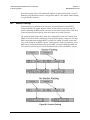
1
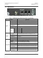
CME-5200
Digicast Media Router ASI Receiver
Comtech EF Data is an ISO 9001
Registered Company
Installation and Operation Manual
Part Number MN/MRASIRCDC.IOM
Revision A
May 10, 2007
Copyright © Comtech EF Data, 2007. All rights reserved. Printed in the USA.
Comtech EF Data, 2114 West 7th Street, Tempe, Arizona 85281 USA, (480) 333-2200, FAX: (480) 333-2161
Table of Contents
PREFACE.................................................................................................................................... V
Customer Support....................................................................................................................................... v
About this Manual ..................................................................................................................................... vi
Reporting Comments or Suggestions Concerning this Manual............................................................... vi
Conventions and References ..................................................................................................................... vi
Cautions and Warnings............................................................................................................................ vi
Metric Conversion .................................................................................................................................. vii
Recommended Standard Designations ................................................................................................... vii
Trademarks ............................................................................................................................................. vii
Electromagnetic Compatibility (EMC) Compliance.............................................................................. vii
Emissions Compliance ........................................................................................................................... vii
EN61000 Compliance............................................................................................................................. vii
Safety Compliance ...................................................................................................................................viii
EN60950 Compliance............................................................................................................................viii
Low Voltage Directive (LVD) ..............................................................................................................viii
Warranty Policy ......................................................................................................................................... ix
Limitations of Warranty .......................................................................................................................... ix
Exclusive Remedies.................................................................................................................................. x
CHAPTER 1.
INTRODUCTION ...........................................................................................1–1
1.1
Introduction................................................................................................................................ 1–1
1.2
Standard Features...................................................................................................................... 1–1
1.3
Performance ............................................................................................................................... 1–2
1.4
Configuration ............................................................................................................................. 1–2
1.5
Specifications .............................................................................................................................. 1–3
1.6
Terminology ............................................................................................................................... 1–4
CHAPTER 2. INSTALLATION & INITIAL CONFIGURATION.................................................2-1
i
CME-5200 Digicast Media Router ASI Receiver
Revision A
MN/MRASIRCDC.IOM
2.1
Major Assembly ..........................................................................................................................2-1
2.2
Unpacking....................................................................................................................................2-1
2.3
Installation...................................................................................................................................2-2
2.4
Initial Configuration...................................................................................................................2-3
CHAPTER 3. INTERFACE PINOUTS ......................................................................................3-1
3.1
Pinout Overview..........................................................................................................................3-1
3.2
DC Power.....................................................................................................................................3-1
3.3
RJ-12 Terminal ...........................................................................................................................3-1
3.4
RJ-12 Redundancy......................................................................................................................3-2
3.5
RJ-45 Ethernet ............................................................................................................................3-2
3.1
BNC ..............................................................................................................................................3-2
3.6
ASI IN ..........................................................................................................................................3-2
CHAPTER 4.
4.1
DEVICE MANAGEMENT VIA USER INTERFACES .....................................4-1
Introduction.................................................................................................................................4-1
4.2
Web Interface ..............................................................................................................................4-1
4.2.1
Administrative Configuration ..............................................................................................4-2
4.2.2
Network Configuration ........................................................................................................4-4
4.2.3
IGMP Configuration ............................................................................................................4-5
4.2.4
Unicast Routing Configuration ............................................................................................4-6
4.2.5
PID Configuration ................................................................................................................4-7
4.2.6
MPEG Transport Stream Route Configuration ....................................................................4-8
4.2.7
Statistics ...............................................................................................................................4-9
4.3
Terminal Interface ....................................................................................................................4-10
4.3.1
Main Menu .........................................................................................................................4-11
4.3.2
Network Configuration Menu ............................................................................................4-11
4.3.3
Administration Menu .........................................................................................................4-12
4.3.3.1
Port Number Configuration .......................................................................................4-12
4.3.4
IGMP Configuration Menu ................................................................................................4-13
4.3.5
Unicast Routing Configuration Menu ................................................................................4-13
4.3.6
PID Configuration Menu....................................................................................................4-14
4.3.7
ASI MPEG TS Configuration Menu..................................................................................4-14
4.3.8
Stats Menu..........................................................................................................................4-15
4.3.8.1
DMA Stats Menu.......................................................................................................4-16
4.3.8.2
(MPE/IP) Downlink Stats Menu................................................................................4-16
ii
CME-5200 Digicast Media Router ASI Receiver
Revision A
MN/MRASIRCDC.IOM
4.3.8.2.1
Detailed Downlink Stats Menu..............................................................................4-17
4.3.8.2.2
Detailed Advanced Downlink Stats Menu ............................................................4-17
4.3.8.3
MPEG TS Stats Menu ...............................................................................................4-18
4.3.8.3.1
Detailed MPEG TS Stats Menu.............................................................................4-18
4.3.8.3.2
Detailed MPEG TS Advanced Stats Menu............................................................4-19
4.3.8.4
Ethernet Stats Menu ..................................................................................................4-19
4.4
Telnet Interface .........................................................................................................................4-20
4.5
Trivial File Transfer Protocol (TFTP) ....................................................................................4-21
4.6
Simple Network Management Protocol (SNMP) (Future)....................................................4-22
APPENDIX A.
SOFTWARE UPGRADE ............................................................................ A–1
A.1
Introduction............................................................................................................................... A–1
A.2
Web Interface ............................................................................................................................ A–2
A.3
Telnet or Terminal Interface ................................................................................................... A–3
APPENDIX B.
B.1
IP ROUTING SUPPORT.............................................................................. B-1
Introduction................................................................................................................................ B-1
B.2
IP Configuration ........................................................................................................................ B-1
B.2.1
Unicast Routing................................................................................................................... B-1
B.2.2
Multicast Routing................................................................................................................ B-2
B.3
Section Packing .......................................................................................................................... B-3
Tables
Table 1-1. CME-5200 Digicast Media Router ASI-R – Specifications....................................................1–3
Table 2-1. CME-5200 Digicast Media Router ASI-R – Standalone Configuration ..................................2-1
iii
CME-5200 Digicast Media Router ASI Receiver
Revision A
MN/MRASIRCDC.IOM
Figures
Figure 1-1. CME-5200 Digicast Media Router ASI-R – Front Panel.......................................................1–1
Figure 1-2. CME-5200 Digicast Media Router ASI-R .............................................................................1–2
Figure 1-3. CME-5200 Digicast Media Router ASI-R – Rear Panel........................................................ 1–3
Figure 3-1. CME-5200 Digicast Media Router ASI-R – Rear Panel.........................................................3-1
Figure 4-1. Connecting to the ASI-R .........................................................................................................4-1
Figure 4-2. Home (“Splash”) page.............................................................................................................4-2
Figure 4-3. Administrative Configuration page .........................................................................................4-2
Figure 4-4. Network Configuration page...................................................................................................4-4
Figure 4-5. IGMP Configuration page.......................................................................................................4-5
Figure 4-6. Unicast Routing Configuration page.......................................................................................4-6
Figure 4-7. PID Configuration page ..........................................................................................................4-7
Figure 4-8. MPEG Transport Stream Route Configuration page ..............................................................4-8
Figure 4-9. Statistics page..........................................................................................................................4-9
Figure 4-10. Menu Hierarchy (via Terminal Interface) ...........................................................................4-10
Figure 4-11. Main Menu ..........................................................................................................................4-11
Figure 4-12. Network Configuration Menu .............................................................................................4-11
Figure 4-13. Administration Menu ..........................................................................................................4-12
Figure 4-14. IGMP Configuration Menu .................................................................................................4-13
Figure 4-15. Unicast Routing Configuration Menu .................................................................................4-13
Figure 4-16. PID Configuration Menu.....................................................................................................4-14
Figure 4-17. ASI MPEG TS Configuration Menu ...................................................................................4-14
Figure 4-18. Stats Menu...........................................................................................................................4-15
Figure 4-19. Stats Menu Hierarchy (via Terminal Interface) ..................................................................4-15
Figure 4-20. DMA Stats Menu ................................................................................................................4-16
Figure 4-21. Downlink Stats Menu..........................................................................................................4-16
Figure 4-22. Detailed Downlink Stats Menu ...........................................................................................4-17
Figure 4-23. Detailed Advanced Downlink Stats Menu ..........................................................................4-17
Figure 4-24. MPEG TS Stats Menu ........................................................................................................4-18
Figure 4-25. Detailed MPEG TS Stats Menu ..........................................................................................4-18
Figure 4-26. Detailed MPEG TS Advanced Stats Menu .........................................................................4-19
Figure 4-27. Ethernet Stats Menu ............................................................................................................4-19
Figure 4-28. Starting Telnet Session........................................................................................................4-20
Figure 4-29. Main Menu via Telnet .........................................................................................................4-20
Figure A-1. TFTP Download (via Web).................................................................................................. A–2
Figure A-2. TFTP Download (via Terminal)........................................................................................... A–3
Figure A-3. TFTP Download Complete (via Terminal) .......................................................................... A–4
Figure B-1. Multicast Mapping (IP to MAC) ........................................................................................... B-2
Figure B-2. Section Packing ..................................................................................................................... B-3
iv
Preface
Customer Support
Contact the Comtech EF Data Customer Support Department for:
•
•
•
Product support or training
Reporting comments or suggestions concerning manuals
Information on upgrading or returning a product
A Customer Support representative may be reached at:
Comtech EF Data
Attention: Customer Support Department
2114 West 7th Street
Tempe, Arizona 85281 USA
480.333.2200 (Main Comtech EF Data number)
480.333.4357 (Customer Support Desk)
480.333.2161 FAX
To return a Comtech EF Data product (in-warranty and out-of-warranty) for repair or replacement:
•
•
•
•
Contact the Comtech EF Data Customer Support Department. Be prepared to supply the
Customer Support representative with the model number, serial number, and a description
of the problem.
Request a Return Material Authorization (RMA) number from the Comtech EF Data
Customer Support representative.
Pack the product in its original shipping carton/packaging to ensure that the product is not
damaged during shipping.
Ship the product back to Comtech EF Data. (Shipping charges should be prepaid.)
For Online Customer Support:
An RMA number request can be requested electronically by contacting the Customer Support
Department through the online support page at www.comtechefdata.com/support.asp:
•
Click on “Return Material Authorization” for detailed instructions on our return
•
Click on the “RMA Request Form” hyperlink, then fill out the form completely before
•
Send e-mail to the Customer Support Department at [email protected].
procedures.
sending.
For information regarding this product’s warranty policy, refer to the Warranty Policy, p. ix.
v
CME-5200 Digicast Media Router ASI Receiver
Preface
Revision A
MN/MRASIRCDC.IOM
About this Manual
This manual provides installation and operation information, functional capabilities, and
performance specifications for the Comtech EF Data (CEFD) CME-5200 Digicast Media
Router ASI Receiver – referred to throughout this manual as “the ASI-R.” This
publication additionally provides information on how to connect the ASI-R to other data
transport equipment.
This is a technical document intended for earth station engineers, technicians, and
operators responsible for the operation and maintenance of the CME-5200 Digicast
Media Router ASI Receiver.
Reporting Comments or Suggestions Concerning this Manual
Comments and suggestions regarding the content and design of this manual are
appreciated. To submit comments, please e-mail the Comtech EF Data Technical
Publications Department at [email protected].
Conventions and References
Cautions and Warnings
IMPORTANT or NOTE indicates a statement that is associated with the task
being performed or information critical for proper equipment function.
IMPORTANT
CAUTION indicates a hazardous situation that, if not avoided, may result in
minor or moderate injury. CAUTION may also be used to indicate other
unsafe practices or risks of property damage.
WARNING indicates a potentially hazardous situation that, if not avoided,
could result in death or serious injury.
\
Examples of
Multi-Hazard Formats
vi
CME-5200 Digicast Media Router ASI Receiver
Preface
Revision A
MN/MRASIRCDC.IOM
Metric Conversion
Metric conversion information is located on the inside back cover of this manual. This
information is provided to assist the operator in cross-referencing non-Metric to Metric
conversions.
Recommended Standard Designations
Recommended Standard (RS) Designations are interchangeable with the designation of
the Electronic Industries Association (EIA).
Trademarks
Windows is a trademark of the Microsoft Corporation.
Other product names mentioned in this manual may be trademarks or registered
trademarks of their respective companies and are hereby acknowledged. Comtech EF
Data neither endorses nor otherwise sponsors any such production or services referred
herein.
Electromagnetic Compatibility (EMC) Compliance
This is a Class B product. In a domestic environment, it may cause radio interference that
requires the user to take adequate protection measures.
Emissions Compliance
This equipment has been tested and found to comply with the limits for a Class B digital
device, pursuant to Part 15 of the Federal Communications Commision (FCC) rules, and
EN55022 Class B requirements.
These limits are designed to provide reasonable protection against harmful interference
when the equipment is operated in a commercial environment.
EN61000 Compliance
This equipment meets the EMC/immunity characteristics for the limits and methods of
measurement for information technology equipment as per EN61000-4-2, EN61000-4-3,
EN61000-4-4, EN61000-4-5 and EN61000-4-11.
This equipment meets the EMC/immunity characteristics for the limits and methods of
measurement of mains harmonics & flicker for information technology equipment as per
CE EN61000-3-2 and EN61000-3-3.
vii
CME-5200 Digicast Media Router ASI Receiver
Preface
Revision A
MN/MRASIRCDC.IOM
Safety Compliance
EN60950 Compliance
Applicable testing is routinely performed as a condition of manufacturing on all units to
ensure compliance with safety requirements of EN60950.This equipment meets the
Safety of Information Technology Equipment specification as defined in EN60950.
Low Voltage Directive (LVD)
The following information is applicable for the European Low Voltage Directive
(EN60950):
<HAR>
!
Type of power cord required for use in the European Community.
CAUTION: Double-pole/Neutral Fusing
ACHTUNG: Zweipolige bzw. Neutralleiter-Sicherung
International Symbols:
Symbol
Definition
Symbol
Definition
~
Alternating Current
Protective Earth /
Safety Ground
Fuse
Chassis Ground
For additional symbols, refer to Cautions and Warnings listed
earlier in this Preface.
NOTE
viii
CME-5200 Digicast Media Router ASI Receiver
Preface
Revision A
MN/MRASIRCDC.IOM
Warranty Policy
Comtech EF Data products are warranted against defects in material and
workmanship for a period of two years from the date of shipment. During the
warranty period, Comtech EF Data will, at its option, repair or replace products
that prove to be defective.
For equipment under warranty, the owner is responsible for freight to Comtech
EF Data and all related customs, taxes, tariffs, insurance, etc. Comtech EF Data
is responsible for the freight charges only for return of the equipment from the
factory to the owner. Comtech EF Data will return the equipment by the same
method (i.e., Air, Express, Surface) as the equipment was sent to Comtech EF
Data.
All equipment returned for warranty repair must have a valid RMA number issued
prior to return and be marked clearly on the return packaging. Comtech EF Data
strongly recommends all equipment be returned in its original packaging.
Comtech EF Data Corporation’s obligations under this warranty are limited to
repair or replacement of failed parts, and the return shipment to the buyer of the
repaired or replaced parts.
Limitations of Warranty
The warranty does not apply to any part of a product that has been installed,
altered, repaired, or misused in any way that, in the opinion of Comtech EF Data
Corporation, would affect the reliability or detracts from the performance of any
part of the product, or is damaged as the result of use in a way or with equipment
that had not been previously approved by Comtech EF Data Corporation.
The warranty does not apply to any product or parts thereof where the serial
number or the serial number of any of its parts has been altered, defaced, or
removed.
The warranty does not cover damage or loss incurred in transportation of the
product.
The warranty does not cover replacement or repair necessitated by loss or damage
from any cause beyond the control of Comtech EF Data Corporation, such as
lightning or other natural and weather related events or wartime environments.
The warranty does not cover any labor involved in the removal and or
reinstallation of warranted equipment or parts on site, or any labor required to
diagnose the necessity for repair or replacement.
ix
CME-5200 Digicast Media Router ASI Receiver
Preface
Revision A
MN/MRASIRCDC.IOM
The warranty excludes any responsibility by Comtech EF Data Corporation for
incidental or consequential damages arising from the use of the equipment or
products, or for any inability to use them either separate from or in combination
with any other equipment or products.
A fixed charge established for each product will be imposed for all equipment
returned for warranty repair where Comtech EF Data Corporation cannot identify
the cause of the reported failure.
Exclusive Remedies
Comtech EF Data Corporation’s warranty, as stated is in lieu of all other
warranties, expressed, implied, or statutory, including those of merchantability
and fitness for a particular purpose. The buyer shall pass on to any purchaser,
lessee, or other user of Comtech EF Data Corporation’s products, the
aforementioned warranty, and shall indemnify and hold harmless Comtech EF
Data Corporation from any claims or liability of such purchaser, lessee, or user
based upon allegations that the buyer, its agents, or employees have made
additional warranties or representations as to product preference or use.
The remedies provided herein are the buyer’s sole and exclusive remedies.
Comtech EF Data shall not be liable for any direct, indirect, special, incidental, or
consequential damages, whether based on contract, tort, or any other legal theory.
x
Chapter 1. INTRODUCTION
Figure 1-1. CME-5200 Digicast Media Router ASI-R – Front Panel
1.1
Introduction
The Comtech EF Data (CEFD) CME-5200 Digicast Media Router ASI Receiver –
referred to throughout this manual as “the ASI-R” – is an economical ASI-to-IP Receiver
providing price-versus-performance unparalleled in today’s market.
The ASI-R receives Multiprotocol Encapsulated (MPE) packets (as specified in ETSI EN
301 192) over an MPEG-2 Asynchronous Serial Interface (ASI) input and decapsulates
Ethernet/IP Unicast or Multicast packets. Additionally, the ASI-R can be configured to
provide transport stream (TS) over IP.
1.2
Standard Features
Based on an embedded architecture utilizing a MIPS CPU and eCOS Operating System,
the ASI-R provides the following features:
•
•
•
•
•
•
•
•
High Reliability
ASI Input at rates as high as 213 Mbps
Ethernet Egress Rate as high as 85 Mbps (1,500 byte packets)
Support for Multicast and Unicast IP datagrams
MPE Section Packing and Non-Section Packing on a PID-by-PID basis
Support for Transport Stream over IP
Support for all valid PIDs in 8192 range
64 PIDs
1–1
CME-5200 Digicast Media Router ASI Receiver
Introduction
•
•
•
•
•
•
1.3
Revision A
MN/MRASIRCDC.IOM
MPEG-2 188/204-byte operation
Support for 802.1Q VLAN Tags
IGMP for Multicast Route Announcements
Configurable Telnet and HTTP ports for security
Color LEDs for status monitoring and rapid fault isolation
Device management (monitor, control and configuration):
o Web Interface
o Terminal Interface
o TFTP for remote field software/firmware upgrade
o Telnet
o SNMP V2 (Private and MIB II) Support (Future)
Performance
The ASI-R provides the following performance characteristics:
Item
1.4
Value
Maximum Ingress (ASI Input)
213 Mbps 188-byte Mode
Maximum Packets per Second (PPS)
(Minimum Packet Size 64 bytes)
15,000 PPS
Maximum Bits Per Second
(Maximum Packet Size 1,518 bytes)
85 Mbps 188-byte Mode
Latency
Less than 10 mS
Configuration
A typical ASI-R configuration, shown in in Figure 1-2, enbales IP-based multimedia content
(video, audio and data) to be delivered over a high-speed ASI link and distributed to remote
devices connected to the ASI-R via an Ethernet LAN.
Figure 1-2. CME-5200 Digicast Media Router ASI-R
1–2
CME-5200 Digicast Media Router ASI Receiver
Introduction
1.5
Revision A
MN/MRASIRCDC.IOM
Specifications
Figure 1-3. CME-5200 Digicast Media Router ASI-R – Rear Panel
Table 1-1. CME-5200 Digicast Media Router ASI-R – Specifications
Parameter
Physical
Specification
Dimensions
Weight
Power
7.125” L x 8.125” W x 1.72” H (18.1L x 20.6W x 4.4H cm)
< 6 lbs (2.7 kg)
2.5 mm with screw type connector
ASI Copper Input
BNC (75Ω)
Ethernet
(10/100BaseT)
Terminal
Redundancy
Blue
Red
Green
LEDs
Green
Green
Electrical
Power Input /
Consumption
ASI (Copper)
Ethernet
(10/100BaseT)
Console
Redundancy
Temperature
Operating
Environmental
Storage
(Non-operating)
Humidity
Operating
Storage
(Non-operating)
Altitude
Operating
Storage
(Non-operating)
RJ-45
RJ-12
RJ-12
POWER
ALARM
M-ACT
E-ACT
Power
Alarm
MPE data activity
Ethernet traffic/activity
E-LINK
Ethernet connection to hub/switch operational
48 to 248 VAC 50/60 Hz converted to +5VDC @ 2.5A / < 7 W
EN50083-9
IEEE 802.3u
RS-232
RS-232
32° to 104° Farenheit (0° to 40° Celsius)
-22° to 150° Farenheit (-30° to 65° Celsius)
10% to 75% Non-condensing
Relative Humidity to 95% with temperature ≤ 95° Farenheit (35° Celsius)
Up to 10,000 feet (3048 m) above sea level
Survival up to 50,000 feet (15240 m) above sea level for up to 15 hours
1–3
CME-5200 Digicast Media Router ASI Receiver
Introduction
1.6
Revision A
MN/MRASIRCDC.IOM
Terminology
The following table defines the acronyms referred to throughout this manual:
Acronym
Definition
ASI
Asynchronous Serial Interface
ARP
Address Resolution Protocol
CEFD
Comtech EF Data
DVB
Digital Video Broadcast
EBU
European Broadcasting Union
ETS
European Telecommunications Standard
FTP
File Transfer Protocol
IANA
Internet Assigned Number Authority
IGMP
Internet Gateway Messaging Protocol
IP
Internet Protocol
IRD
Integrated Receiver Decoder
LAN
Local Area Network
MAC
Media Access Control
MIB
Management Information Base
MPE
Multi-Protocol Encapsulation
MPEG
Moving Pictures Expert Group
MPEGTS
Moving Pictures Expert Group Transport System
MUX
Multiplexer
PID
Packet Identifier
RS
Reed Solomon
SNMP
Simple Network Management Protocol
SYSLOG
System Log
TCP
Transmission Control Protocol
TERM
Terminal
TSD
Transport Stream Demultiplexer
UDP
User Datagram Protocol
VLAN
Virtual Local Area Network
1–4
Chapter 2. INSTALLATION &
INITIAL CONFIGURATION
2.1
Major Assembly
The CME-5200 Digicast Media Router ASI-R is available in a standalone configuration.
Table 2-1 lists the components provided with a standard configuration. In the event any
listed item is missing, please contact Comtech EF Data Customer Support:
Table 2-1. CME-5200 Digicast Media Router ASI-R – Standalone Configuration
Quantity
2.2
Description
1
CME-5200 Digicast Media Router ASI-R
1
SPU24-102 Power Supply
1
IEC AC Power Cord
1
CA-TERMINAL Terminal Cable
1
CD (includes this manual and a Quick Start reference)
1
Quick Start sheet
Unpacking
The shipping container and packing materials should be retained for possible reshipment.
Perform a receiving inspection as follows:
•
•
Inspect the shipping container for damage. If there is damage to the shipping
container, notify the carrier.
Check to determine that all parts, materials and documentation have been shipped
•
•
with the router.
Inspect the ASI-R for possible physical damage.
Test the ASI-R for proper operation.
2-1
CME-5200 Digicast Media Router ASI Receiver
Installation & Initial Configuration
•
Contact Comtech EF Data Customer Support if the shipment is:
!
!
!
2.3
Revision A
MN/MRASIRCDC.IOM
Incomplete
Physically damaged
Inoperable
Installation
The ASI-R is designed for ease of installation and configuration. Once the unit has
been removed from the packing container, please follow these instructions:
Step
1
Procedure
Place the ASI-R on a flat surface with free-air flow where the LEDs can be
clearly observed with unrestricted access to the rear panel of the unit.
2
Connect the DC power connection to the connection labeled PWR on the
back of the unit and tighten the restraining nut to ensure secure operation.
3
Connect an RJ-45 Ethernet cable (patch cord) to the port labeled
ETHERNET. This cable should be connected to an Ethernet concentrator
(hub) or switch.
4
Connect a terminal cable (supplied) to the port labeled TERM. This cable
should be connected to a PC’s serial port (DB-9) to initially configure the
ASI-R.
5
Connect the AC power cord between a standard wall outlet and the power
supply. The blue LED will illuminate.
6
It is recommend that the ASI cable NOT be connected until the
unit has been completely configured.
IMPORTANT
7
Upon startup, the following LEDs will illuminate on the ASI-R front panel:
LED
Function Label
Blue
POWER
LED illuminates if power is properly applied
Red
ALARM
LED may illuminate since the unit is not yet
configured
Green
M-ACT
LED illuminates if MPE data is present
Green
E-ACT
LED flashes if there is Ethernet traffic/activity
Green
E-LINK
LED illuminates if the Ethernet connection to
the Hub/Switch is operational
2-2
Description
CME-5200 Digicast Media Router ASI Receiver
Installation & Initial Configuration
2.4
Revision A
MN/MRASIRCDC.IOM
Initial Configuration
The initial configuration involves setting up the IP parameters via the terminal cable.
Once the IP parameters have been configured, the terminal cable can be removed. The
terminal cable should be stored in a known location, since it may be needed in the future.
To configure the IP parameters:
Step
Procedure
1
Using a terminal emulator on a PC such as HyperTerminal™ or
TeraTerm™, set up the communication port as follows:
• 38,400 BAUD
• 8 Data Bits
• 1 Stop Bit
• No Parity
• No Flow Control
2
Press the <ENTER> key on the PC – the ASI-R’s menu should be
displayed.
3
Press “N” for Network Menu.
4
Press “I” for the IP Address, Enter the IP Address and press <ENTER>.
5
Press “M” for the Subnet Mask. Enter the Subnet Mask and press
<ENTER>.
6
Press “G” for the Default Gateway IP Address. Enter the Default
Gateway Address and press <ENTER>.
7
Press “S” to save the parameters.
8
Press “Y” to confirm the saving of parameters.
9
Press “X” to exit to the main menu.
10
Press “P” to configure the PIDs. Enter a valid number of PIDs and press
<ENTER>.
11
Press “Y” to confirm the saving of parameters.
12
Press “X” to exit to the main menu.
At this point, the unit has been configured for full operation and the terminal cable may
be removed. The ASI cable may now be safely attached to the ASI IN (input) port. For
continued operation the unit may be managed via the Terminal Interface; however, it is
recommended to use the Web Interface for ease of management.
2-3
CME-5200 Digicast Media Router ASI Receiver
Installation & Initial Configuration
Revision A
MN/MRASIRCDC.IOM
Notes:
2-4
Chapter 3. INTERFACE PINOUTS
3.1
Pinout Overview
The rear panel interface (Figure 3-1) provides all necessary external connections between
the CME-5200 Digicast Media Router ASI-R and other equipment.
Figure 3-1. CME-5200 Digicast Media Router ASI-R – Rear Panel
3.2
3.3
DC Power
Pin
Definition
Center
+5VDC
Outer Ring
GND
Pin
Definition
1
GND
RJ-12 Terminal
2
TXD
3
RXD
4
GND
5
N/C
6
N/C
3-1
CME-5200 Digicast Media Router ASI Receiver
Interface Pinouts
3.4
3.5
3.6
Revision A
MN/MRASIRCDC.IOM
RJ-12 Redundancy
Pin
Definition
1
GND
2
TXD
3
RXD
4
GND
5
N/C
6
N/C
Pin
1
2
3
4
5
6
7
8
Definition
TXD+
TXDRXD+
N/C
N/C
RXDN/C
N/C
RJ-45 Ethernet
BNC ASI IN
Pin
Definition
Center
8B/10B 270 Mbps
Outer Ring
GND
3-2
Chapter 4. DEVICE MANAGEMENT
VIA USER INTERFACES
4.1
Introduction
Management of the ASI-R is simple and intuitive. There are a variety of ways to
configure and manage the ASI-R:
•
•
•
•
•
4.2
Web Interface via a LAN-based Desktop Browser
Terminal Interface via direct connection to a PC’s asynchronous serial port
Telnet Interface via a LAN
TFTP for remote terminal upgrades
SNMP Private MIB and MIB II (Future)
Web Interface
The Web Interface, operating under standard HyperText Transport Protocol (HTTP), is
used to communicate with and command the ASI-R via a HyperText Markup Languagebased Graphical User Interface (GUI). To utilize the Web Interface, a LAN connection
must exist between the ASI-R and a PC with a browser such as Microsoft Internet
Explorer.
Once a valid IP Address, Subnet Mask and Default Gateway have been entered into the
ASI-R, activate a browser on the desktop. Enter the IP address for the ASI-R into the
URL field as shown in Figure 4-1. If the port number has been modified from the
Standard 80 via the Terminal Interface, then the port number must be appended with a
colon to the IP address.
Figure 4-1. Connecting to the ASI-R
A successful connection between the PC and the ASI-R will result in the display of the
“splash page” shown in Figure 4-2.
4-1
CME-5200 Digicast Media Router ASI Receiver
Device Management via User Interfaces
Revision A
MN/MRASIRCDC.IOM
Figure 4-2. Home (“Splash”) page
4.2.1
Administrative Configuration
Figure 4-3. Administrative Configuration page
4-2
CME-5200 Digicast Media Router ASI Receiver
Device Management via User Interfaces
IMPORTANT
Revision A
MN/MRASIRCDC.IOM
Beginning with the Administrative Configuration page (Figure 4-3), all
pages containing configurable parameters feature a login dialog box at
the bottom of the page. Changes to the ASI-R configuration will not be
accepted without a valid user name and password.
The ASI-R Administrative Configuration page contains the following configurable
parameters:
User Name
The ASI-R’s User Name is user configurable and is used for connecting to the
unit via IP management services.
The default user name is comtech.
Password
The ASI-R’s Password is user configurable and is used for authenticating a user
when connecting via IP management services. The password is case sensitive and
must be entered carefully.
When the password is changed, the user will be prompted to enter the password
twice to verify it is correct.
The default password is comtech.
System Contact
Contact information of the system administrator for support.
System Location
The physical location where the unit has been installed.
Enable Telnet
Enables Telnet application on the ASI-R.
SNMP IP Address
Defines the SNMP server that can connect to the unit.
Login Required
A user name and password are required to make any changes to the ASI-R
configuration.
Update Firmware
Allows software/firmware changes to be made. User name and password is
required for security.
4-3
CME-5200 Digicast Media Router ASI Receiver
Device Management via User Interfaces
4.2.2
Revision A
MN/MRASIRCDC.IOM
Network Configuration
Figure 4-4. Network Configuration page
The ASI-R’s Network Configuration page has the following configurable parameters:
IP Address
The IP Address assigned to the ASI-R’s LAN interface. The IP Address is
entered in dotted decimal format.
Subnet Mask
The Subnet Mask assigned to the ASI-R’s LAN interface. The Subnet Mask is
entered in dotted decimal format and is typically 255.255.255.0 for a C-Class
mask, 255.255.0.0 for a B-Class mask or 255.0.0.0 for an A-Class mask.
Default Gateway
The Default Gateway assigned to the ASI-R’s LAN interface. The Default
Gateway is entered in dotted decimal format and must be within the subnet of the
IP Address assigned to the LAN interface. The Default Gateway is the address
of a local router to which all non-local subnet traffic will be directed.
Login Required
A user name and password are required to make any changes to the ASI-R
configuration.
4-4
CME-5200 Digicast Media Router ASI Receiver
Device Management via User Interfaces
4.2.3
Revision A
MN/MRASIRCDC.IOM
IGMP Configuration
Figure 4-5. IGMP Configuration page
Enable
Select the Boolean if IGMP version 3 (IGMPv3) is to be supported. If the
Boolean is not selected, all received Multicast IP is forwarded to the Ethernet. If
support is enabled, no Multicast IP will be forwarded to the Ethernet until a
subscriber has joined the Multicast group.
Query Period
How often a solicitation is made for Multicast subscribers.
Maximum Tries
The maximum number of attempts the ASI-R will make for soliciting for
Multicast subscribers before the Multicast stream is pruned off.
Response Timeout
The maximum amount of time the ASI-R will wait for Multicast Subscribers
before the Multicast stream is pruned off.
4-5
CME-5200 Digicast Media Router ASI Receiver
Device Management via User Interfaces
4.2.4
Revision A
MN/MRASIRCDC.IOM
Unicast Routing Configuration
Figure 4-6. Unicast Routing Configuration page
Allow Unicast
Select the Boolean if Unicast routing is to be supported. If the Boolean is not
selected, only Multicast IP support will be provided.
Route unknown to default gateway
If Unicast routing support is enabled, for IP packets that are received and are not
destined to the local subnet, all non-local Unicast packets are directed to the
default gateway for routing.
Filter on TSD MAC
This Boolean must be enabled if Unicast routing support is enabled, and the IP
Encapsulator on the head-end is configured for Unicast routes with configured
MAC addresses for each Transport Stream Demultiplexer (TSD).
TSD MAC
If the Filter on TSD MAC Boolean is enabled, this field is the MAC address used
for routing incoming MPE packets carrying Unicast. The configured MAC
address must match the incoming MAC address in the MPE packet. If the MAC
addresses do not match, the packet will be silently discarded.
VLAN
VLAN is supported on the ASI-R. Packets that are received on the ASI interface
as 802.1Q are routed to the Ethernet with the VLAN tags intact. The valid
ranges of the VLAN ID are 0 to 4095.
4-6
CME-5200 Digicast Media Router ASI Receiver
Device Management via User Interfaces
4.2.5
Revision A
MN/MRASIRCDC.IOM
PID Configuration
Figure 4-7. PID Configuration page
Packet Size
Determines the packet size of the incoming transport streams. Two packet sizes
are support 188 or 204. For 204-byte packets, the trailing 16 bytes are discarded.
PID
The ASI-R supports up to 64 PIDs. All PIDs are entered in four (4) character
hexadecimal format. For example, PID 25 would be entered as PID 0025, PID
200 would be entered as 0200 and PID 1353 would be entered as 1353. All
inactive PIDs should be set to a value of 0x1FFF (Not Defined).
Mode
The ASI-R supports both MPE decoding to IP and MPEG Transport Stream
(MPEGTS) over IP. The user must select the mode of operation for the desired PID.
IP (DVB-TS)
The IP address configured to send the MPEG TS over IP. The address may be
either Unicast or Multicast.
Port (DVB-TS)
The port number configured to send the MPEG TS over IP. The port setting
should be a value greater than 1024.
4-7
CME-5200 Digicast Media Router ASI Receiver
Device Management via User Interfaces
4.2.6
Revision A
MN/MRASIRCDC.IOM
MPEG Transport Stream Route Configuration
Figure 4-8. MPEG Transport Stream Route Configuration page
Upon selection of the desired input, a small popup window appears that shows all
services on the particular input. This is achieved by looking at the Program Stream
Information (PSI) that is contained in the Program Association Table (PAT) and Program
Mapping Table (PMT) – all detected programs will be displayed for either input port
selected.
Enable
Enables or disables the route.
Name
The name of the incoming program that is extracted from the Program Service
Information.
Program Number
The program number to be routed to the Ethernet as Transport Stream over IP.
PMT PID Number
The PMT PID to be routed to the Ethernet as Transport Stream over IP.
Destination IP
The IP address to be used when routing the Transport Stream over Ethernet IP.
Port Number
The Port Number to be used when routing the Transport Stream over Ethernet IP.
4-8
CME-5200 Digicast Media Router ASI Receiver
Device Management via User Interfaces
4.2.7
Revision A
MN/MRASIRCDC.IOM
Statistics
Figure 4-9. Statistics page
4-9
CME-5200 Digicast Media Router ASI Receiver
Device Management via User Interfaces
4.3
Revision A
MN/MRASIRCDC.IOM
Terminal Interface
The Terminal Interface provides the user with a textual configuration dialog for
configuring the ASI-R. This method of configuration should be used for initial
configuration of the unit; i.e., configuring the network parameters for the unit but not for
normal operation. The Web (HTTP) Interface is recommended for operational
management.
The Terminal Interface allows the entire unit to be configured and managed, but this
interface can only be used while a serial connection is present between the ASI-R and a
PC. The screens shown in this section are displayed via a Telnet connection.
The same menu information is displayed via the serial interface with some specific
features only available via this access method – these ‘serial interface only’ features are
noted in this section. Detailed information is provided about the menu features in
Chapter 4.2 Web Interface.
Network Configuration
Menu (4.3.2)
Administration
Menu (4.3.3)
IGMP Configuration
Menu (4.3.4)
Main Menu
(4.3.1)
Unicast Routing
Config Menu (4.3.5)
PID Configuration
Menu (4.3.6)
MPEG TS Config
Menu (4.3.7)
Stats Menu
(4.3.8)
See Figure 4-19
for hierarchy
Figure 4-10. Menu Hierarchy (via Terminal Interface)
Figure 4-10 shows the hierarchal structure of the Terminal Interface-based menus, and
the sections in this chapter which provide figures of these submenu pages.
Once the terminal interface is connected, as described in Chapter 2.4 Initial
Configuration, press the <ENTER> key . The user should observe the the Main Menu as
shown in Figure 4-11.
4-10
CME-5200 Digicast Media Router ASI Receiver
Device Management via User Interfaces
4.3.1
Revision A
MN/MRASIRCDC.IOM
Main Menu
Figure 4-11. Main Menu
4.3.2
Network Configuration Menu
Figure 4-12. Network Configuration Menu
4-11
CME-5200 Digicast Media Router ASI Receiver
Device Management via User Interfaces
4.3.3
Revision A
MN/MRASIRCDC.IOM
Administration Menu
Figure 4-13. Administration Menu
4.3.3.1
Port Number Configuration
In addition to the features illustrated, one additional feature is available, for security
reasons, via the serial interface only. Modifying the port numbers prevents attacks on “well
known” ports by devices known as port scanners. This feature is configuration of the TCP
Port number for Telnet and HTTP protocols. Option <M> allows the operator to modify the
standard port numbers for Telnet (23) and HTTP (80) to prevent unauthorized access to the
device. Care should be taken not to use a reserved standard port number.
4-12
CME-5200 Digicast Media Router ASI Receiver
Device Management via User Interfaces
4.3.4
Revision A
MN/MRASIRCDC.IOM
IGMP Configuration Menu
Figure 4-14. IGMP Configuration Menu
4.3.5
Unicast Routing Configuration Menu
Figure 4-15. Unicast Routing Configuration Menu
4-13
CME-5200 Digicast Media Router ASI Receiver
Device Management via User Interfaces
4.3.6
Revision A
MN/MRASIRCDC.IOM
PID Configuration Menu
Figure 4-16. PID Configuration Menu
4.3.7
ASI MPEG TS Configuration Menu
Figure 4-17. ASI MPEG TS Configuration Menu
4-14
CME-5200 Digicast Media Router ASI Receiver
Device Management via User Interfaces
4.3.8
Revision A
MN/MRASIRCDC.IOM
Stats Menu
Figure 4-17 shows the hierarchal structure of the Terminal Interface-based Stats menus,
and the sections in this chapter which illustrate the menu pages within this hierarchy.
Figure 4-18. Stats Menu
Stats Menu
(4.3.8)
DMA Stats Menu
(4.3.8.1)
MPE/IP Stats Menu
(4.3.8.2)
MPG TS Stats
Menu (4.3.8.3)
Ethernet Stats
Menu (4.3.8.4)
Detailed Downlink
Stats (4.3.8.2.1)
Detailed MPEG TS
Stats (4.3.8.3.1)
Detailed Downlink
Advanced Stats
(4.3.8.2.2)
Detailed MPEG TS
Advanced Stats
(4.3.8.3.2)
Figure 4-19. Stats Menu Hierarchy (via Terminal Interface)
4-15
CME-5200 Digicast Media Router ASI Receiver
Device Management via User Interfaces
4.3.8.1
Revision A
MN/MRASIRCDC.IOM
DMA Stats Menu
Figure 4-20. DMA Stats Menu
4.3.8.2
(MPE/IP) Downlink Stats Menu
Figure 4-21. Downlink Stats Menu
4-16
CME-5200 Digicast Media Router ASI Receiver
Device Management via User Interfaces
4.3.8.2.1
Revision A
MN/MRASIRCDC.IOM
Detailed Downlink Stats Menu
Figure 4-22. Detailed Downlink Stats Menu
4.3.8.2.2
Detailed Advanced Downlink Stats Menu
Figure 4-23. Detailed Advanced Downlink Stats Menu
4-17
CME-5200 Digicast Media Router ASI Receiver
Device Management via User Interfaces
4.3.8.3
Revision A
MN/MRASIRCDC.IOM
MPEG TS Stats Menu
Figure 4-24. MPEG TS Stats Menu
4.3.8.3.1
Detailed MPEG TS Stats Menu
Figure 4-25. Detailed MPEG TS Stats Menu
4-18
CME-5200 Digicast Media Router ASI Receiver
Device Management via User Interfaces
4.3.8.3.2
Revision A
MN/MRASIRCDC.IOM
Detailed MPEG TS Advanced Stats Menu
Figure 4-26. Detailed MPEG TS Advanced Stats Menu
4.3.8.4
Ethernet Stats Menu
Figure 4-27. Ethernet Stats Menu
4-19
CME-5200 Digicast Media Router ASI Receiver
Device Management via User Interfaces
4.4
Revision A
MN/MRASIRCDC.IOM
Telnet Interface
Telnet provides a textual interface over a LAN. Most PCs have the capability to use
Telnet. To use Telnet on a Microsoft Windows® product, click
, then
.
The Run dialog box is shown in Figure 4-28. In the Open: text window, enter “telnet
xxx.xxx.xxx.xxx,” where xxx.xxx.xxx.xxx is the IP address of the ASI-R. If the port
number has been modified from the Standard 23 via the Terminal Interface, then the port
number must be appended with a colon to the IP address.
Figure 4-28. Starting Telnet Session
The user will be prompted to enter the user name and password to gain access to the
telnet interface.
The default username is comtech and the default password is
NOTE
comtech, both of which are case sensitive.
Once the menu is started, press <ENTER> and the ASI-R Main Menu will display as
shown in Figure 4-29:
Figure 4-29. Main Menu via Telnet
The user may navigate the menus in the same manner as the Terminal Interface. With
specific exceptions as noted in the Terminal Interface section, the menus available via
Telnet and Serial interfaces are identical.
4-20
CME-5200 Digicast Media Router ASI Receiver
Device Management via User Interfaces
4.5
Revision A
MN/MRASIRCDC.IOM
Trivial File Transfer Protocol (TFTP)
The ASI-R supports changes to the resident software and firmware by means of the
Trivial File Transfer Protocol (TFTP). This enables changes to be made remotely via the
LAN interface. It is recommended to use Solarwinds TFTP server application (available
at http://support.solarwinds.net/updates/SelectProgramFree.cfm).
To modify the software and/or firmware, use the following procedures:
Configure the server as follows:
a) File ! Configuration ! Select the ‘TFTP Root Directory’. Set up the location
of the ASI-R files.
b) File ! Configuration ! Select the ‘Security’ tab and make sure ‘Transmit and
Receive’ are selected.
c) Save configuration.
The server is now configured for the file transfer process.
Because the ASI-R stops processing data traffic during the
download process, it is recommended that this upgrade procedure
be performed during scheduled network down time.
IMPORTANT
Do NOT remove power from the unit during the download process.
To modify code via Telnet:
Step
Procedure
1
Start up Solarwinds TFTP server – ensure configuration as described
previously.
2
Ensure that the code provided by CEFD is located in the TFTP Root
directory.
3
Start up Telnet client and initiate a session with the ASI-R as described
in the Telnet Interface section.
4
Select ‘A’ for Administration.
5
Select ‘D’ for Download.
6
Enter ‘1’ for Application code or ‘2’ for FPGA code (the user will be
directed to select Application or FPGA code in the download
instructions provided by CEFD when new code is provided).
7
Enter the IP address of the TFTP server and wait for the message
“Upgrade complete. Press any key to continue.”
This code modification process can also be conducted via the Web Interface, under the
Administration page, or the Terminal Interface under the Main Menu.
IMPORTANT
Under heavy traffic conditions, the TFTP transfer may take several
minutes. The transfer process reported by Solarwinds may show greater
than 100% transferred, but this is a normal condition. Be patient and
allow the transfer to take place.
4-21
CME-5200 Digicast Media Router ASI Receiver
Device Management via User Interfaces
4.6
Revision A
MN/MRASIRCDC.IOM
Simple Network Management Protocol (SNMP) (Future)
Simple Network Management Protocol (SNMP) has not been enabled on this product and
is planned as a future release. However, when enabled, SNMP allows an SNMP Manager
such as OpenView or Castle Rock to be used to remotely manage the ASI-R in an
automated fashion.
The ASI-R supports SNMP versions 1 and 2 (SNMPv1 and SNMPv2). Two types of
Management Information Bases (MIBs) are supported: MIB II and private MIB.
MIB II is the default MIB that is used to gather generic information about the unit, such
as system ‘up’ time, packets sent or received on an interface, etc. MIB II is designed for
only read access, not write access. To read and write configuration parameters over
SNMP requires a private MIB. The private MIB allows parameters to be set on the
Web, Terminal, or Telnet interfaces.
The elements Object Identifiers (OIDs) of the MIB will be listed in the appendix of a
future revision of this manual. CEFD has been assigned an SNMP designator by the
IEEE, and will be found in all elements of the ASI-R’s MIB.
The assigned designator for CEFD (enterprise OID) is 1.3.6.4.1.18723.
NOTE
The ASI-R supports configurable community strings for added security. As a security
precaution, passwords cannot be remotely queried over SNMP.
For SNMP access from a remote network via the public Internet, a VPN connection to the
ASI-R will need to be established using third-party VPN client/server access.
The default community string for the public elements is public and the private
community string is private.
4-22
Appendix A. SOFTWARE
UPGRADE
A.1
Introduction
The ASI-R is enabled to receive an upgrade via Trivial File Transfer Protocol (TFTP)
transmission. Comtech EF Data recommends using the Solarwinds TFTP server
application (available at http://support.solarwinds.net/updates/SelectProgramFree.cfm)
for upgrading the product.
NOTE
The user will be instructed whether to select Application or FPGA
code in the download instructions provided by CEFD when new code is
provided.
Once the TFTP server is enabled and the new file (Application or FPGA) has been
copied to the TFTP server, the procedures outlined in sections A.2 and A.3 may be used
to upgrade the unit.
A–1
CME-5200 Digicast Media Router ASI Receiver
Software Upgrade
A.2
Revision A
MN/MRASIRCDC.IOM
Web Interface
Access the Administrative Configuration menu (Figure A-1):
a) In the Update Firmware section, enter the Unit TFTP Server IP Address.
b) Select Application or FPGA for the Image Type to be upgraded.
c) Enter a valid username and password in the Login Required section (below
the Update Firmware section) then select Update. The software update will
begin to download.
Do NOT power the unit down during the upgrade process.
IMPORTANT
d) When the update is complete, the message “Press any key to continue”
will be displayed.
e) Once the unit is upgraded, reset the unit by entering a valid username and
password in the first Login Required section, then selecting Reset Unit.
Figure A-1. TFTP Download (via Web)
A–2
CME-5200 Digicast Media Router ASI Receiver
Software Upgrade
A.3
Revision A
MN/MRASIRCDC.IOM
Telnet or Terminal Interface
Access the Admin Menu (Figure A-2):
a) Select (D) for Download Image.
b) At the “Image type” prompt, enter 1 for Application or 2 for FPGA.
c) Enter the TFTP IP server address. Once the TFTP IP server address is
entered, the software update will begin to download.
Do NOT power the unit down during the upgrade process.
IMPORTANT
d) When the update is complete, the message “Press any key to continue”
will be displayed (Figure A-3).
e) After the unit has been upgraded, reset the unit by selecting (R) for Reset and
‘Y’ to confirm the reset.
Figure A-2. TFTP Download (via Terminal)
A–3
CME-5200 Digicast Media Router ASI Receiver
Software Upgrade
Revision A
MN/MRASIRCDC.IOM
Figure A-3. TFTP Download Complete (via Terminal)
A–4
Appendix B. IP ROUTING
SUPPORT
B.1
Introduction
The ASI-R provides state-of-the-art MPE decapsulation based on the DVB Specification
for Data Broadcasting (EN 301 192). The ASI-R provides the following configuration
features:
•
•
•
•
•
B.2
IP Decapsulation per Multi-Protocol Encapsulation (EN 301 192)
Unicast Routing
Multicast Routing
Section Packing and Non-Section Packing
IGMP Version 3
IP Configuration
Both Unicast and Multicast IP datagrams are encapsulated per the Multi-Protocol
Encapsulation specification. Routing of datagrams is accomplished by configuration of
PIDs in the ASI-R, as described in the following section.
B.2.1
Unicast Routing
Unicast routing provides point-to-point delivery of IP datagrams. Routes for Unicast IP
packets are configured according to the following:
•
•
IP Addresses, which fall into three classes, namely: A (0.0.0.0 to
127.255.255.255), B (128.0.0.0 to 191.255.255.255) and C (192.0.0.0 to
223.255.255.255).
Medium Access Control (MAC) Addresses, which identify the destination
device (next-hop) to which the packets are sent. The least-significant bit of the
B-1
CME-5200 Digicast Media Router ASI Receiver
IP Routing Support
Revision A
MN/MRASIRCDC.IOM
first byte of the six-byte MAC address is a ‘0’. For example, 0x00 11 22 33 44 55
is a Unicast address.
Unicast is supported by the ASI-R as it would be in any routed network. Packets received
by the ASI-R are routed to the Ethernet if they meet the subnet criteria or the ASI-R is
configured to route non-local packets to a default gateway.
The ASI-R uses Classless Inter-Domain Routing (CIDR) notation in which a ‘slash’
followed by a decimal number is used to represent the number of bits for the mask; e.g.,
/32 is 255.255.255.255 and /24 is 255.255.255.0.
As stated previously, part of the route configuration is a MAC address that is assigned for
delivery of the packet when it is encapsulated into MPE. The MAC address typically
identifies the remote receiver (physical device); e.g., satellite terminal, DTV terminal, or
cable receiver.
B.2.2
Multicast Routing
Multicast routing provides point-to-multipoint delivery of IP datagrams. Routes for
multicast IP packets are configured according to the following:
•
•
•
IP Addresses, which fall into class D (224.0.0.0 to 239.255.255.255)
Medium Access Control (MAC) Addresses, which identify the frames as
multicast. The least-significant bit of the first byte of the six-byte MAC address
is a ‘1’. For example, 0x01 00 5E 00 00 01 is a multicast address.
Broadcast frames are identified by the MAC Address, 0x FF FF FF FF FF FF.
Multicast IP addresses are related to multicast MAC addresses as follows:
•
The lower 23 bits of the IP address are mapped into the lower 23 bits of the MAC
address.
Figure B-1. Multicast Mapping (IP to MAC)
Several examples of the relationship are:
•
•
•
Received IP: 239.1.1.10 = MAC: 0x01 00 5E 01 01 0A
Received IP: 224.10.10.10 = MAC: 0x01 00 5E 0A 0A 0A
Received IP: 228.63.10.10 = MAC: 0x01 00 5E 3F 0A 0A
B-2
CME-5200 Digicast Media Router ASI Receiver
IP Routing Support
Revision A
MN/MRASIRCDC.IOM
Note that the upper 5 bits of the multicast IP address are ignored in the MAC so that 32
Multicast group IP addresses map to a single MAC address. This implies further filtering
is required at the end device.
B.3
Section Packing
Section packing is a technique to provide more optimal utilization of the MPEG-2
Transport Stream (TS) packet structure. When section packing is not used, each TS
packet (containing the MPE section) can carry no more than a single section. This often
results in wasted payload capacity when the sections are less than 184 bytes.
The section packing feature allows more than a single MPE section to be carried by an
MPEG-2 TS packet, thereby minimizing wasted payload capacity. In the case of a large
MPE section that spans multiple MPEG-2 packets, the ending of an MPE section may
occur in the middle of an MPEG-2 packet. In this instance, with section packing, a new
MPE section begins immediately after the first MPE section has finished without any
‘fill’ (wasted) bytes having to be inserted before the start of the next MPEG-2 packet.
Figure B-2. Section Packing
B-3
CME-5200 Digicast Media Router ASI Receiver
IP Routing Support
Revision A
MN/MRASIRCDC.IOM
Notes:
B-4
METRIC CONVERSIONS
Units of Length
Unit
Centimeter
Inch
Foot
Yard
Mile
Meter
Kilometer
Millimeter
1 centimeter
—
0.3937
0.03281
0.01094
6.214 x 10⁻⁶
0.01
—
—
1 inch
2.540
—
0.08333
0.2778
1.578 x 10⁻⁵
0.254
—
25.4
1 foot
30.480
12.0
—
0.3333
1.893 x 10⁻⁴
0.3048
—
—
1 yard
91.44
36.0
3.0
—
5.679 x 10⁻⁴
0.9144
—
—
1 meter
100.0
39.37
3.281
1.094
6.214 x 10⁻⁴
—
—
—
1 mile
1.609 x 10⁵
6.336 x 10⁴
5.280 x 10³
1.760 x 10³
—
1.609 x 10³
1.609
—
1 mm
—
0.03937
—
—
—
—
—
—
1 kilometer
—
—
—
—
0.621
—
—
—
Temperature Conversions
Unit
° Fahrenheit
° Centigrade
32° Fahrenheit
—
(water freezes)
212° Fahrenheit
—
(water boils)
-459.6° Fahrenheit
—
Formulas
0
C = (F - 32) * 0.555
100
F = (C * 1.8) + 32
273.1
(absolute 0)
Units of Weight
Unit
Gram
Ounce
Avoirdupois
Ounce
Troy
Pound
Avoirdupois
Pound
Troy
Kilogram
1 gram
—
0.03527
0.03215
0.002205
0.002679
0.001
1 oz. avoir.
28.35
—
0.9115
0.0625
0.07595
0.02835
1 oz. troy
31.10
1.097
—
0.06857
0.08333
0.03110
1 lb. avoir.
453.6
16.0
14.58
—
1.215
0.4536
1 lb. Troy
373.2
13.17
12.0
0.8229
—
0.3732
1 kilogram
1.0 x 10³
35.27
32.15
2.205
2.679
—
2114 WEST 7TH STREET TEMPE ARIZONA 85281 USA
480 • 333 • 2200 PHONE
480 • 333 • 2161 FAX