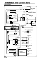
1
R
EN
TDM-7583R
TDM-7581R
TDM-7580R
DE
FM/MW/LW/RDS Cassette Receiver
• OWNER'S MANUAL
Please read before using this equipment.
• BEDIENUNGSANLEITUNG
Lesen Sie diese Bedienungsanleitung bitte vor
Gebrauch des Gerätes.
FR
• MODE D'EMPLOI
Veuillez lire avant d'utiliser cet appareil.
• MANUAL DE OPERACIÓN
Léalo antes de utilizar este equipo.
ES
• ISTRUZIONI PER L'USO
Si prega di leggere prima di utilizzare il
attrezzatura.
• ANVÄNDARHANDLEDNING
Innan du använder utrustningen bör du läsa
igenom denna användarhandledning.
IT
ALPINE ELECTRONICS, INC.
Tokyo office: 1-1-8 Nishi Gotanda,
Shinagawa-ku,
Tokyo 141-8501, Japan
Tel.: (03) 3494-1101
ALPINE ELECTRONICS OF AMERICA, INC.
19145 Gramercy Place, Torrance,
California 90501, U.S.A.
Tel.: 1-800-ALPINE-1 (1-800-257-4631)
ALPINE ELECTRONICS OF CANADA, INC.
Suite 203, 7300 Warden Ave. Markham,
Ontario L3R 9Z6, Canada
Tel.: 1-800-ALPINE-1 (1-800-257-4631)
Je ll Moon Hwa CO.
23-5, 1 Ga, Pil-dong, Jung-gu, Seoul, Korea
ALPINE ELECTRONICS OF AUSTRALIA PTY. LTD.
6-8 Fiveways Boulevarde Keysborough,
Victoria 3173, Australia
Tel.: (03) 9769-0000
ALPINE ELECTRONICS GmbH
Kreuzerkamp 7-11 40878 Ratingen, Germany
Tel.: 02102-45 50
ALPINE ITALIA S.p.A.
Via C. Colombo 8, 20090 Trezzano Sul Naviglio
MI, Italy
Tel.: 02-48 47 81
ALPINE ELECTRONICS FRANCE S.A.R.L.
(RCS PONTOISE B 338 101 280)
98, Rue De La Belle Etoile, Z.I. Paris Nord Il
B.P. 50016 F-95945, Roissy, Charles De Gaulle
Cedex, France
Tel.: 01-48 63 89 89
ALPINE ELECTRONICS OF U.K., LTD.
13 Tanners Drive, Blakelands, Milton Keynes
MK14 5BU, U.K.
Tel.: 01908-61 15 56
ALPINE ELECTRONICS DE ESPAÑA, S.A.
Portal De Gamarra 36, Pabellón 32
01013 Vitoria (Alava)-Apdo. 133, Spain
Tel.: 34-45-283588
Designed by ALPINE Japan
Printed in Korea (Y)
68P01434K21-O
SE
CD changer for TDM-7583R/TDM7581R/TDM-7580R
CD-Wechsler für TDM-7583R/TDM7581R/TDM-7580R
Changeur CD pour TDM-7583R/TDM7581R/TDM-7580R
Cambiador de CD para
TDM-7583R/TDM-7581R/TDM7580R
Cambia CD per TDM-7583R/TDM7581R/TDM-7580R
CD-växlare för TDM-7583R/TDM7581R/TDM-7580R
CHA-S624
CHA-1214
CHM-S620
Alpine CD Changers Give You More!
More musical selections, more versatility, more convenience.
An Alpine CD Changer adds more musical choices to your sound system. All models can be controlled from Alpine head units and
deliver excellent sound quality. The CHA-S624 is a high-performance 6-disc changer with a new M DAC, Ai-NET compatibility, Optical
Digital Output, 150 Disc Title Memory and CD TEXT. The CHA-1214 Ai-NET model holds 12 discs, and the CHM-S620 M-Bus model
is a super-compact 6-disc changer.
Von Alpine CD-Wechslern haben Sie mehr!
Mehr Musikauswahl, mehr Vielseitigkeit, mehr Komfort.
Mit einem Alpine CD-Wechsler erweitern Sie die Musikauswahl Ihres Systems. Sämtliche Modelle lassen sich von einer AlpineBedieneinheit aus steuern und liefern hervorragende Klangqualität. Der CHA-S624 ist ein Ai-NET-kompatibler Hochleistungs-Wechsler
für 6 CDs mit dem neuen M-DAC, Digitalausgang für Glasfaserkabel, CD-Titelspeicher für 150 Titel und CD-TEXT. Das Ai-NETModell CHA-1214 nimmt 12 CDs auf, und der M-Bus-kompatible CHM-S620 ist ein superkompakter Wechsler für 6 CDs.
Changeurs de CD Alpine : vous avez le choix!
Plus de sélections musicales, plus de souplesse, plus de confort.
Un changeur de CD Alpine permet d'augmenter la plage des sélections musicales de votre système embarqué. Tous les modèles peuvent
être contrôlés à partir des autoradios Alpine et offrent une excellente qualité audio. Le modèle CHA-S624 est un changeur 6 disques
ultra performant compatible Ai-NET et équipé d'un convertisseur N/A standard, d'une sortie optique numérique, d'une mémoire d'une
capacité de 150 titres et de la fonction CD TEXT. Le modèle CHA-1214 Ai-NET peut contenir 12 disques. Le modèle CHM-S620 MBus est un changeur 6 disques super compact.
¡Los cambiadores Alpine de CD le ofrecen más!
Más selecciones musicales, más versatilidad y más ventajas.
Un cambiador Alpine de CD añade más opciones musicales a su equipo de sonido. Todos los modelos pueden controlarse desde las
unidades principales de Alpine y proporcionar un sonido de calidad excepcional. El modelo CHA-S624 es un cambiador de 6 discos de
alto rendimiento con el nuevo DAC "M" y compatibilidad con Ai-NET, salida digital óptica, memoria de títulos de 150 discos y TEXTO
CD. El modelo CHA-1214 Ai-NET admite 12 discos y el modelo CHM-S620 Bus-M es un cambiador de 6 discos y tamaño reducido.
I caricatori CD Alpine danno di più!
Più scelta, più versatilità, più comodità.
Un caricatore CD Alpine offre maggiore scelta. Tutti i modelli possono essere controllati tramite le unità di controllo Alpine e producono
un suono di qualità eccellente. CHA-S624 è un caricatore a 6 dischi Ai NET compatibile e dotato di un nuovo M DAC, di un'uscita
ottica digitale, memorizzazione dei titoli di 150 dischi e CD TEXT. Il modello CHA-1214 Ai NET può contenere un massimo di 12
dischi, mentre il modello CHM-S620 M-Bus è un caricatore a 6 dischi ultra compatto.
Alpines CD-växlare ger mer!
Fler musikval, mer variation, större bekvämlighet.
Med Alpines CD-växlare i systemet får du större musikalisk valfrihet. Alla modeller kan styras från Alpines huvudenheter och ger
enastående ljudkvalitet. CHA-S624 är en högpresterande växlare för 6 skivor med en ny M D/A-omvandlare, kompatibel med Ai-NET,
optisk digitalutgång, titelminne för 150 skivor och CD-TEXT. Modellen CHA-1214 Ai-NET rymmer 12 skivor och modellen CHMS620 M-Bus är en superkompakt växlare för 6 skivor.
ENGLISH
Contents
Operating Instructions
WARNING
WARNING .................................................. 2
CAUTION ................................................... 2
PRECAUTIONS ......................................... 2
Basic Operation
Detaching the Front Panel .................................. 4
Attaching the Front Panel .................................. 4
Initial System Start-Up ...................................... 4
Turning Power On and Off ................................ 5
Non Fading Pre-Out (N.F.P.) On and Off
(TDM-7583R only) ........................................ 5
Adjusting Source Signal Levels ......................... 5
Adjusting Volume/Bass/Treble/Balance
(Between Left and Right Channels)/Fader
(Between Front and Rear Speakers) ............... 5
Turning Loudness On/Off .................................. 5
Radio Operation
Manual Tuning ................................................... 6
Automatic Seek Tuning ..................................... 6
Manual Storing of Station Presets ..................... 6
Automatic Memory of Station Presets ............... 7
Tuning to Preset Stations ................................... 7
RDS Operation
Setting RDS Reception Mode and Receiving
RDS Stations .................................................. 8
Recalling Preset RDS Stations ........................... 8
Turning Emergency Alarm On or Off ................ 9
Receiving Traffic Information ............................ 9
Cassette Player Operation
Inserting/Ejecting Cassette .............................. 11
Normal Play and Pause .................................... 11
Dolby B NR (Noise Reduction)
(TDM-7583R only) ...................................... 11
Repeat Play ...................................................... 11
Blank Skip (B.SKIP) ........................................ 11
Fast Forward and Rewind ................................ 12
Scanning Programmes ..................................... 12
Manual Reverse ............................................... 12
Programme Sensor (P.S.) ................................. 12
CD Changer Operation
Controlling CD Changer (Optional) ................ 13
Music Sensor (M.S.) Skip ................................ 13
Fast Forward and Backward ............................ 13
Repeat Play on Single Track or Entire Disc .... 14
M.I.X. (Random) Play ..................................... 14
Disc Scan ......................................................... 14
To Display CD Titles (TDM-7583R only) ....... 15
Titling Discs (TDM-7583R only) .................... 15
Erasing Disc Title (TDM-7583R only) ............ 15
Remote Control Operation
Controls on Remote Control
(TDM-7583R only) ...................................... 16
Battery Replacement ........................................ 17
Information
In Case of Difficulty ........................................ 18
Specifications ................................................... 19
Installation and Connections
WARNING ....................................................... 20
CAUTION ........................................................ 20
Precautions ....................................................... 20
Installation ....................................................... 21
Connections ..................................................... 22
PTY (Programme Type) Tuning ........................ 9
Receiving Traffic Information While Playing
Tape or Radio ................................................. 9
* Dolby noise reduction manufactured under license from
Dolby Laboratories Licensing Corporation. "DOLBY" and
the double-D symbol are trademarks of Dolby Laboratories Licensing Corporation.
Priority News ................................................... 10
Receiving RDS Regional (Local) Stations ...... 10
1-EN
EN
WARNING
WARNING
The exclamation point within an equilateral
triangle and "WARNING" are intended to alert the
user to the presence of important operating
instructions.
Failure to heed the instructions will result in
severe injury or death.
CAUTION
The exclamation point within an equilateral
triangle and "CAUTION" are intended to alert the
user to the presence of important operating
instructions.
Failure to heed the instructions can result in injury
or material damage.
DO NOT DISASSEMBLE OR ALTER.
HALT USE IMMEDIATELY IF A PROBLEM APPEARS.
Doing so may result in an accident, fire or electric shock.
Failure to do so may cause personal injury or damage to
the product. Return it to your authorized Alpine dealer or
the nearest Alpine Service Centre for repairing.
KEEP SMALL OBJECTS SUCH AS BATTERY OUT OF
THE REACH OF CHILDREN.
Swallowing them may result in serious injury. If
swallowed, consult a physician immediately.
USE THE CORRECT AMPERE RATING WHEN
REPLACING FUSES.
Failure to do so may result in fire or electric shock.
DO NOT OPERATE ANY FUNCTION THAT TAKES
YOUR ATTENTION AWAY FROM SAFELY DRIVING
YOUR VEHICLE.
Any function that requires your prolonged attention
should only be performed after coming to a complete stop.
Always stop the vehicle in a safe location before
performing these functions. Failure to do so may result in
an accident.
KEEP THE VOLUME AT A LEVEL WHERE YOU CAN
STILL HEAR OUTSIDE NOISE WHILE DRIVING.
Failure to do so may result in an accident.
USE THIS PRODUCT FOR MOBILE 12V
APPLICATIONS.
DO NOT MIX NEW BATTERIES WITH OLD
BATTERIES. INSERT WITH THE CORRECT BATTERY
POLARITY.
When inserting the batteries, be sure to observe proper
polarity (+ and –) as instructed. Rupture or chemical
leakage from the battery may cause fire or personal injury.
PRECAUTIONS
Temperature
Be sure the temperature inside the vehicle is between
+60°C (+140°F) and –10°C (+14°F) before turning your
unit on.
Tape Slack
Check and make sure any slack in the tape is taken up
before inserting the tape into the unit. A loose tape can get
caught in the mechanism and cause damage to the unit
and the tape itself. Tighten the tape by inserting a pencil
or a similar instrument into the spindle hole and turn until
all the slack has been taken up.
Use for other than its designed application may result in
fire, electric shock or other injury.
DO NOT PLACE HANDS, FINGERS OR FOREIGN
OBJECTS IN INSERTION SLOTS OR GAPS.
Doing so may result in personal injury or damage to the
product.
DO NOT BLOCK VENTS OR RADIATOR PANELS.
Doing so may cause heat to build up inside and may result
in fire.
2-EN
Excessively Thin Tape
C-120 type cassette tapes are not recommended for use in
automobile tape players.
Precision Tape Mechanism
Prevent any foreign objects from entering the cassette
opening as the precision mechanism and tape head may be
damaged.
Never play dirty or dusty tapes – they can damage the tape
head.
EN
Tape Head Cleaning
Periodic cleaning (approximately every 20 hours of use)
of the tape head with a wet type head-cleaning cassette
tape (available at audio stores) is necessary for best
performance.
Fuse Replacement
When replacing the fuse(s), the replacement must be of
the same amperage as shown on the fuse holder. If the
fuse blows more than once, carefully check all electrical
connections for shorted circuitry. Also have your vehicle's
voltage regulator checked.
Maintenance
If you have problems, do not attempt to repair the unit
yourself. Return it to your Alpine dealer or the nearest
Alpine Service Station for servicing.
Installation Location
Make sure the TDM-7583R/TDM-7581R/TDM-7580R
will not be installed in a location subjected to:
•
•
•
•
Direct sun and heat
High humidity and water
Excessive dust
Excessive vibrations
Handling the Detachable Front Panel
• Do not expose to rain or water.
• Do not drop or apply shock.
3-EN
Basic Operation
POWER/SETUP 2
MODE/LOUD
1
Detaching the Front Panel
1
2
3
Press the POWER button to turn off the power.
Press the
(Release) button until the front
panel pops out.
Grasp the left side of the front panel and pull it
out.
1
• Connectable to Remote Control Interface
Box
You can operate this unit from the vehicle's
control unit when an Alpine Remote Control
Interface Box (optional) is connected. For
details, contact your Alpine dealer.
Initial System Start-Up
1
NOTES
• The front panel may become hot (especially the
connector terminals), this is not malfunction.
• To protect the front panel, place it in the supplied
carrying case.
Attaching the Front Panel
1
2
First, insert the right side of the front panel into
the main unit. Align the groove on the front panel
with the projection on the main unit.
Push the left side of the front panel until it locks
firmly into the main unit.
2
1
NOTE
Before attaching the front panel, make sure that there is
no dirt or dust on the connector terminals and no foreign
object between the front panel and the main unit.
4-EN
c
Immediately after installing or applying power to
the unit, it should be initialized. To do this, first,
remove the detachable front panel. Behind the
front panel, to the right of the connector, there is
a small hole. Using a ballpoint pen or other
pointed object, press the RESET switch mounted
behind this hole to complete the initialization
procedure.
RESET Switch
Turning Power On and Off
1
Press the POWER button to turn on the unit.
NOTE
The unit can be turned on by pressing any other button
except the eject c button.
The volume level gradually increases to the
previous level you were listening to before the
unit was turned off.
Press the POWER button again to turn off the
unit.
NOTE
When the power is turned on for the very first time after
the unit is connected to the vehicle's battery, the unit
produces sound with the volume level 12, loudness on in
the tuner mode.
Adjusting Volume/Bass/Treble/
Balance (Between Left and Right
Channels)/Fader (Between Front
and Rear Speakers)
1
→ VOL
2
NOTES
• Initial mode is N.F.P. OFF.
• Set the N.F.P. to OFF unless the subwoofer is used.
Press the 6 and 5 buttons until the desired
sound is obtained in each mode.
NOTE
The settings of the Bass and Treble will be individually
memorized for each source (FM, MW, LW, Tape and CD
Changer) until the setting is changed.
Depending on the connected devices, some functions and
display indications do not work.
Press and hold the Eject (c) button for at least 3
seconds.
With each press, N.F.P. is toggled On or Off.
N.F.P. ON:
In this position, the Pre-Output on the TDM7583R will not be affected by the fader. This is
ideal for driving a subwoofer amplifier.
N.F.P. OFF:
Returns to normal fader mode.
→ BASS
→ TREB
FAD ←
BAL ←
NOTE
If the 6 or 5 button is not pressed in 5 seconds after
selecting the BASS, TREBLE, BALANCE and FADER
modes, the unit automatically sets in the VOLUME mode.
Non Fading Pre-out (N.F.P.) On and
Off (TDM-7583R only)
1
Press the MODE button repeatedly to choose
the desired mode.
Each press changes the modes as follows:
Turning Loudness On/Off
1
Press and hold the LOUD button for at least
2 seconds to activate or deactivate the loudness
mode. The display shows "LD" when the
loudness mode is activated.
Adjusting Source Signal Levels
If the difference in volume level between the tape
player and FM radio is too great, adjust the FM
signal level as follows.
1
2
3
Press and hold the SETUP button for at least 3
seconds.
Press the Preset 1 button to select the FM signal
level HI (High) or LO (Low) to make the signal
levels between the FM band and tape player
closer.
Each press toggles between FM-LV HI and FMLV LO.
Press the SETUP button to cancel the adjusting
mode.
5-EN
EN
Radio Operation
SOURCE
DN g
TUNE / A.ME
BAND
F
f UP
Preset buttons (1 through 6)
Manual Tuning
1
2
3
Press the SOURCE button until radio frequency
appears in the display.
Press the BAND button repeatedly until the
desired radio band is displayed.
Each press changes the radio bands as follows:
→ F1 → F2 → MW → LW
4
3
Press the TUNE button repeatedly until "DX
SEEK" and "SEEK" disappears from the display.
NOTE
The initial mode is DX-SEEK.
4
Press the DN g or f UP button to move
downward or upward one step respectively until
the desired station frequency is displayed.
NOTE
The ST indicator appears on the display when a Stereo
FM station is tuned in. If the stereo FM signal becomes
weak, the ST indicator disappears from the display and
the unit automatically switches the mode from stereo to
monaural to reduce the noise. When the signal becomes
strong enough, the unit automatically switches back to
the stereo mode.
Automatic Seek Tuning
1
2
Press the SOURCE button until radio frequency
appears in the display.
Press the BAND button repeatedly until the
desired radio band is displayed.
Each press changes the radio bands as follows:
→ F1 → F2 → MW → LW
6-EN
Press the TUNE button to illuminate the DX and
SEEK indicators in the display.
With the DX mode activated, both strong and
weak stations will be tuned in the Auto-Seek
operation.
Press again to return to the local mode. The DX
indicator will turn off and the SEEK indicator will
remain illuminated. Now, only strong stations will
be tuned.
Press the DN g or f UP button to
automatically seek a station downward or
upward respectively.
When the unit finds a station, the unit stops at
that station.
Press the same button again to seek the next
station.
Manual Storing of Station Presets
1
2
3
Select the radio band and tune in a desired radio
station you wish to store in the preset memory.
Make sure that the function indicator at the top
side of the "F" button illuminates, then press and
hold any one of the preset buttons (1 through
6) for at least 2 seconds until the station
frequency on the display blinks.
Press the preset button into which you wish to
store the station while the frequency display is
blinking (within 5 seconds).
The display changes from blinking to steady
lighting indicating that the station has been
memorized. The display shows the band, preset
No. with a triangle (9) and station frequency
memorized.
4
Repeat the procedure to store up to 5 other
stations onto the same band.
To use this procedure for other bands, simply
select the band desired and repeat the
procedure.
Tuning to Preset Stations
1
2
A total of 24 stations can be stored in the preset
memory (6 stations for each band; FM1, FM2,
MW and LW).
NOTE
If a preset memory has already been set in the same
preset location, it will be cleared and the new station will
be memorized.
Automatic Memory of Station
Presets
1
2
Press the SOURCE button until the frequency
appears in the display.
Press the BAND button repeatedly until the
desired band is displayed.
Each press changes the radio bands as follows:
→ F1 → F2 → MW → LW
3
Make sure that the function indicator at the top
side of the "F" button illuminates, then press the
station preset button that has your desired radio
station in memory.
The display shows the band, preset number with
a triangle and frequency of the station selected.
Press the SOURCE button until the frequency
appears in the display.
Press the BAND button until the desired radio
band appears in the display.
Each press changes the radio bands as follows:
→ F1 → F2 → MW → LW
3
Press and hold the A. ME. button for at least 2
seconds.
The frequency on the display continues to
change while the automatic memory is in
process.
The tuner will automatically seek and store 6
strong stations in the selected band in order of
signal strength.
When the automatic memory has been
completed, the tuner goes to the station stored in
the preset location No. 1.
NOTE
If no stations are stored, the tuner will return to the
original station you were listening to before the auto
memory procedure began.
7-EN
RDS Operation
POWER/SETUP
DN g
AF / T.INFO
f UP
Setting RDS Reception Mode and
Receiving RDS Stations
The RDS (Radio Data System) is a radio
information system using the 57 kHz subcarrier of
regular FM broadcast. The RDS allows you to
receive a variety of information such as traffic
information, station names, and to automatically
re-tune to a stronger transmitter that is
broadcasting the same programme.
1
2
Press the AF button to activate the RDS mode.
The display shows "AF" when the RDS mode is
activated.
Press the DN g or f UP button to tune in
the desired RDS station.
NOTE
When the BAND button is pressed and held for more than
2 seconds while a station name is displayed, the display
shows the station frequency for 5 seconds.
When the RDS station signal received has
become weak:
• AF seek mode, press and hold the AF button for
at least 2 seconds to have the unit
automatically seek for a stronger station in the
AF list.
If there is no AF station, the display shows
"SEEK END."
3
Press the AF button to deactivate the RDS
mode.
Tips
The RDS digital data includes the followings:
PI
Programme Identification
PS
Programme Service Name
AF
List of Alternative Frequecncies
TP
Traffic Programme
TA
Traffic Announcement
PTY
Programme Type
EON
Enhanced Other Networks
8-EN
PTY
F
3
Preset buttons
(1 through 6)
Recalling Preset RDS Stations
1
2
3
Press the AF button to activate the RDS mode.
The display shows "AF" when the RDS mode is
activated.
Make sure that the function indicator at the top
side of the "F" button illuminates, then press the
preset button in which your desired RDS station
is preset.
If the preset station's signal is weak, the unit
automatically searches and tunes to a stronger
station in the AF (Alternative Frequencies) list.
If the preset station and the stations in the AF list
cannot be received:
Press the same preset button again within 5
seconds to have the unit search for a station in
the PI (Programme Identification) list.
If there are still no stations receivable in the
area, the unit displays the frequency of the
preset station and the preset indicator
disappears.
If the signal level of the Regional (Local) station
being tuned becomes too weak to receive, press
the same preset button to tune in a Regional
station in other district.
NOTE
For presetting the RDS stations, refer to the Radio
Operations section. The RDS stations can be preset in
the F1 and F2 bands only.
NOTE
If no button is pressed within 5 seconds after pressing the
PTY button, the PTY mode will be automatically cancelled.
Turning Emergency Alarm On or Off
1
2
3
Press and hold the SETUP button for at least 3
seconds.
3
Press the Preset 3 button repeatedly to select
the PTY31 ON or PTY31 OFF mode.
In the PTY31 ON mode, the unit will make an
emergency announcement when the unit
receives the PTY31 (Emergency Broadcast)
signal.
Press the SETUP button to activate the selected
mode.
→ LIGHT M ↔ CLASSICS ↔ OTHER M ←
4
Receiving Traffic Information
1
2
Press the T.INFO button to activate the Traffic
Information mode.
The display shows "T-INFO" when the Traffic
Information mode is activated.
Press the DN g or f UP button to select
your desired traffic information station. When a
traffic information station is tuned in, the TP
indicator lights up.
Traffic information is heard only when it is being
broadcast. If traffic information is not being
broadcast, the unit is set in the standby mode.
When a traffic information broadcast begins, the
unit automatically receives it and the display
shows "TRF-INFO" for 5 seconds and returns to
the PS display.
5
1
2
Press the T.INFO button repeatedly until the
T.INFO indicator appears in the display.
Press the DN g and f UP buttons to
select a traffic information station if necessary.
• When a traffic information broadcast starts, the
unit automatically mutes the tape player or the
regular FM broadcast.
• When the traffic information broadcast finishes,
the unit automatically returns to the original
source play before the traffic information
broadcast began.
When traffic information stations cannot be
received:
In the tuner mode:
When the TP signal can no longer be received,
an alarm will be sounded after 1 minute.
In the Tape mode:
When the TP signal can no longer be received,
the traffic information station of another
frequency will be selected automatically.
PTY (Programme Type) Tuning
NOTE
The receiver is equipped with the EON (Enhanced Other
Networks) function in order to keep track of additional
alternative frequencies to the AF list. The EON indicator
appears while an RDS EON station is being received. If
the station being received does not broadcast the traffic
information, the receiver automatically tunes in the
related station that broadcasts the traffic information
when it occurs.
Press the "F" button.
The function indicator at the top side of the "F"
button will turn off.
Press the PTY button to activate the PTY mode.
The Programme Type of the station being
currently received will be displayed for 5 seconds.
• If there is no receivable PTY broadcast, "NO
PTY" will be displayed for 5 seconds.
• If no RDS station can be received, the display
shows "NO RDS."
Press the "F" button to activate the normal
mode. The function indicator at the top side of
the "F" button will illuminate.
Receiving Traffic Information While
Playing Tape or Radio
NOTES
• If the traffic information broadcast signal falls below a
certain level, the unit remains in the receiving mode for
1 minute. If the signal remains below a certain level for
over 1 minute, the unit produces an alarming sound.
• If you do not want to listen to the traffic information
being received, lightly press the T. INFO button to skip
that traffic information message. The T. INFO mode
will remain in the ON position to receive the next
traffic information message.
• If the volume level is changed while receiving traffic
information, the changed volume level will be
memorized. When traffic information is received next
time, the volume level will be automatically adjusted
to the level memorized.
2
Press the PTY button within 5 seconds after
selecting the programme type to start searching
for a station in the selected programme type.
The chosen programme type indicator blinks during
searching and lights when a station is found.
If no station is found, "NO PTY" will be displayed
for 5 seconds.
When traffic information broadcast is over, the
unit will automatically set in the standby mode.
1
Press the DN g and f UP buttons within 5
seconds after activating the PTY mode to
choose the desired programme type while the
PTY (programme type) is being displayed. Each
press scrolls the programme type by one.
3
Press the T.INFO button to deactivate the Traffic
Information mode.
The T.INFO indicator disappears.
9-EN
RDS Operation
POWER/SETUP
F
NEWS
Priority News
This function allows you to preset to give priority
to the News programme. You will never miss the
News programme as the unit automatically gives
priority to the News programme whenever it
begins broadcasting, and interrupts the
programme you are currently listening. This
feature is functional when your unit is set to a
mode other than the LW and MW modes.
1
2
Press the "F" button.
The function indicator at the top side of the "F"
button will turn off.
Press the NEWS button to activate the
PRIORITY NEWS mode.
"NEWS" lights up in the display.
• To disable the PRIORITY NEWS function,
press the NEWS button.
NOTE
In the PRIORITY NEWS function, unlike in the T.INFO
function, the volume does not increase automatically.
3
Press the "F" button to activate the normal
mode.
The function indicator at the top side of the "F"
button will illuminate.
10-EN
2
Receiving RDS Regional (Local)
Stations
1
2
3
Press and hold the SETUP button for at least 3
seconds to activate the setting mode.
Press the preset 2 button to turn on or off the
REG (Regional) mode.
In the REG OFF mode, the unit automatically
keeps receiving the related local RDS station.
Press the SETUP button to deactivate the setting
mode.
Cassette Player Operation
c
-/J
B.SKIP
Inserting/Ejecting Cassette
1
NR B
2
Insert a cassette tape into the slot with the open
side facing right.
3
When the cassette is loaded, the player
automatically starts tape playback and indicates
"TAPE" in the display.
2
Press the Eject (c) button when you want to
eject the cassette tape.
NOTES
• When power is turned off or the front panel is removed,
the full-logic mechanism will automatically switch to
the PAUSE mode. This protects the tape from being
deformed by the pinch-rollers if left for long periods.
• Auto Metal
When a metal cassette tape is inserted, the player
automatically adjusts to the equalization for metal or
any other high bias tape for optimum sound.
Normal Play and Pause
1
Insert a cassette (or press the source button to
switch from the tuner or CD Changer mode if a
cassette is already inside the tape player).
The player begins playback. The display shows
or
" during tape playback to
"TAPE" and "
show the tape side being played. When the end
of the tape is reached, the unit automatically
stops and reverses the tape to play the other
side of the tape.
REPEAT
Press the :/J button to pause the tape playback.
The display shows "PAUSE."
Press again to resume the tape playback.
Press the Eject (c) button to stop the tape play
and eject the cassette.
The tape-direction indicator disappears.
Dolby B NR (Noise Reduction)
(TDM-7583R only)
1
After inserting a Dolby B NR encoded tape,
press the NR B button.
The display shows the "NR B." The tape noise is
reduced in the Dolby NR mode when a Dolby B
NR encoded tape is played.
Press the NR B button to cancel the Dolby NR
mode.
Repeat Play
1
Press the REPEAT button to play back
repeatedly the current programme being played.
The RPT indicator appears and the programme
will be played repeatedly.
Press the REPEAT button to stop the repeat
play. The RPT indicator disappears.
Blank Skip (B.SKIP)
1
Press the B.SKIP button during tape play to skip
over blank portions of the tape lasting 15
seconds or longer, "B.S." appears on the display.
Press the B.SKIP button to cancel the blank skip
mode. "B.S." disappears from the display.
11-EN
Cassette Player Operation
PROG
DN g
P.S.DN
f UP
P.S.UP
SCAN
Fast Forward and Rewind
Programme Sensor (P.S.)
1
1
2
Press the DN g or f UP button during
tape play to fast rewind or forward the tape
respectively.
The tape side indicator ( or ) blinks and >>
or << moves indicating the direction of the tape.
When the end of the tape is reached in the
rewind mode, the player stops automatically and
begins playing from the beginning of the same
side. When the end of the tape is reached in the
fast forward mode, the player stops automatically
and begins playing from the beginning of the
opposite side.
Press the f UP button during forwarding to
stop fast forwarding and resume tape play.
Press the DN g button during rewinding to
stop rewinding and resume tape play.
The tape side indicator stops blinking.
Scanning Programmes
1
Press the SCAN button to play the first 10
seconds of each programme on the tape.
"SCAN" appears on the display.
Press the SCAN button to cancel the scanning
when the desired programme is found.
NOTE
The SCAN operation cannot detect blank sections of less
than 4 seconds.
Manual Reverse
1
Press the PROG button during tape play to
change the tape direction to play the other side
of the tape.
) change to
The tape side indicators ( and
show which side of the cassette is being played.
12-EN
Press the P.S. DN button once during tape play
to return to the beginning of the current selection
being played.
If you wish to return to a selection further back,
press repeatedly until the number of selections
you would like to skip is shown in the display.
The display will show PS-1 with the first press
and will increase by one with each successive
press up to PS-9. The tape indicator will blink
showing the direction of your search.
Press the P.S. UP button once during tape play
to advance to the beginning of the next selection.
If you wish to advance to a selection further
ahead, press repeatedly until the number of
selections you would like to skip is shown in the
display.
The display will show PS+1 with the first press
and will increase with each successive press up
to PS+9. The tape indicator will blink showing the
direction of your search during searching
operation.
NOTES
• The programme sensor feature is functional in the tape
play mode only.
• You can advance to the 9th (max.) programme or
return to the 8th (max.) programme.
CD Changer Operation
SOURCE
Preset buttons
DN g
-/J
f UP
Controlling CD Changer (Optional)
If an optional Alpine 6-disc CD Changer (M-Bus)
is connected to the 8-pin DIN connector of the
TDM-7583R/TDM-7581R/TDM-7580R you can
control the CD Changer using the TDM-7583R/
TDM-7581R/TDM-7580R.
Music Sensor (M.S.) Skip
1
Press the f UP button once to advance to the
beginning of the next track.
If you wish to advance to a track further ahead,
press repeatedly until the desired track is
reached.
NOTE
The CD controls on the TDM-7583R/TDM-7581R/TDM7580R for the CD operation are functional only when the
CD Changer is interconnected with the TDM-7583R/
TDM-7581R/TDM-7580R.
1
2
3
Press the SOURCE button to activate the CD
Changer.
The display shows the disc number and track
number.
Make sure that the Function indicator illuminates,
then press the Preset buttons to select the
desired disc loaded in the CD Changer.
To pause playback, press the -/J button.
Pressing the -/J button again will resume
playback.
Press the DN g button once to return to the
beginning of the current track.
If you wish to return to the beginning of a track
further back, repeatedly press until you reach the
desired track.
NOTE
The music sensor feature is functional in the play or
pause mode.
Fast Forward and Backward
1
Press and hold the DN g or f UP button to
quickly move backward or forward respectively
until you reach the desired portion.
NOTE
This feature works only in the CD playback mode.
NOTES
• If the "F" indicator is illuminated the Disc Select
buttons become nonfunctional.
• Press the SOURCE button to activate the CHANGER
mode.
• Only compact discs containing the mark shown can be
used.
• We cannot fully guarantee the playback of CD-R (CDRecordable). You cannot playback CD-RW (CDReWritable) on this unit.
13-EN
CD Changer Operation
SOURCE
F
TITLE
Preset buttons
DN g
Repeat Play on Single Track or
Entire Disc
1
2
M.I.X.
f UP
Press the "F" (Function) button.
The function indicator at the top side of the "F"
button will turn off.
SCAN
M.I.X. (Random) Play
1
2
Press the REPEAT button to display "RPT" or
"RPT ALL" to play back repeatedly the track
being currently played or the entire disc selected.
NOTE
Single track cannot be repeated during M.I.X. play.
3
REPEAT
Press "F" button.
The function indicator at the top side of the "F"
button will turn off.
Press the M.I.X. button while the CD is playing or
in the Pause mode.
The M.I.X. indicator will appear in the display.
The tracks on the disc will be played back in a
random sequence.
After all the tracks on the disc have been played
back, the player loads the next disc and begins a
new random sequence.
Random play continues until the M.I.X. mode is
cancelled.
Press the "F" button to activate the normal
mode.
The function indicator at the top side of the "F"
button will illuminate.
Press the M.I.X. button again to cancel the M.I.X.
mode.
The M.I.X. indicator will disappear from the
display.
3
Press the "F" button to activate the normal
mode.
The function indicator at the top side of the "F"
button will illuminate.
Disc Scan
1
2
Press the "F" button.
The function indicator at the top side of the "F"
button will turn off.
Press the SCAN button to play the first 10
seconds of each track on the disc.
The display shows the disc number, "SCAN",
and track number being played during scan play.
Press to the SCAN button to cancel scan play
and resume normal play.
3
14-EN
Press the "F" button to activate the normal
mode.
The function indicator at the top side of the "F"
button will illuminate.
To Display CD Titles
(TDM-7583R only)
6
When entering a title of less than 8 characters
(for example, 3 character title):
After entering 3 characters to complete your title,
the 4th character space will be blinking. Go to
step 7 to complete the title.
Titles can be displayed for the CDs with titles
entered.
(Refer to page 15 to title discs.)
1
Press the TITLE button in the CD mode.
The display will be switched each time the switch
is pressed.
7
2
3
4
5
Press the TITLE button to select the disc title
display mode. (Refer to page 15.)
Make sure that the function indicator at the top
side of the "F" button illuminates, then press the
Preset buttons to select the desired disc to be
titled.
Erasing Disc Title (TDM-7583R only)
1
Press and hold the TITLE button for at least 3
seconds.
The first digit blinks.
2
Press the DN g or f UP button repeatedly
to select the desired letter/numeral/symbol
available for naming.
3
Press the TITLE button to store the first
character.
The first character will stop blinking and the
display will automatically advance to the next
digit. When that digit begins to blink, you may
choose the next letter or symbol of your title.
Press and hold the TITLE button for at least 3
seconds to record the title.
NOTES
• When the memory capacity for the disc titles is used
up, the display shows "FULL DATA" to indicate that
no more title can be memorized.
• When you want to erase a title, enter the " " symbol
into all spaces.
Titling Discs (TDM-7583R only)
1
Repeat the steps 4 and 5 above to complete the
titling. Entering the eighth character,
automatically stores the title into memory.
4
5
Press the TITLE button to select the disc titling
mode. Then press and hold it for at least 3
seconds.
Press and hold the SOURCE button for at least 3
seconds to activate the title erasing mode.
The disc title in the display will blink.
Press the DN g or f UP button repeatedly
until the disc title you want to erase is displayed.
Press and hold the SOURCE button for at least 3
seconds to erase the disc title displayed.
Press and hold the TITLE button for at least 3
seconds to cancel the disc title erasing mode.
15-EN
Remote Control Operation
VOLUME
1
2
3
4
5
6
7
8
MUTE
PWR
ENT
9
!
CD-CHG
BAND
PROG
SOURCE
A.PROC
"
REMOTE CONTROL UNIT
RUE-4185
Controls on Remote Control
(TDM-7583R only)
1 Mute Button
Press the button to lower the volume by 20 dB
instantly. Press the button again to cancel.
7 8 Button
Radio mode: Pressing the button will select, in
ascending order, stations programmed into the
radio's presets as shown below.
2 Power Switch
Press the switch to turn the power on/off.
→ 1 → 2 ... 6
3 -/J Button
Press the button to switch between the Play and
Pause modes for CD or Tape.
CD Changer mode: DISC Select (UP) Button
Press the button to select a disc in ascending
order.
Tape mode: Press the button once during tape
play to advance to the beginning of the next
selection.
4 CD Changer Button
Press the button to change to the CD changer
operation.
5 Band/Programme Button
Radio mode: BAND Button
Press the button and the band will change as
shown below.
→ F1 → F2 → MW → LW
Tape mode: PROG button
Press the button during tape play to change the
tape direction to play the other side of the tape.
6 Volume Adjustment Buttons
To increase the volume level:
Press the L button
To decrease the volume level:
Press the K button
16-EN
8 g Button
Radio mode: SEEK (DN) Button
CD mode: Press the button to go back to the
beginning of the current track.
Tape mode: Press the button during tape play to
fast rewind the tape respectively.
9 f Button
Radio mode: SEEK (UP) Button
CD mode: Press the button to advance to the
beginning of the next track.
Tape mode: Press the button during tape play to
fast forward the tape respectively.
! 9 Button
Radio mode: Pressing the button will select, in
descending order, stations programmed into the
radio's presets as shown below.
→ 6 → 5 ... 1
CD Changer mode: DISC Select (DN) Button
Press the button to select a disc in descending
order.
Tape mode: Press the button once during tape
play to return to the beginning of the current
selection being played.
Battery Replacement
Applicable battery: Use two "AAA" sized dry
batteries or equivalent.
1
Opening the battery cover
Slide out the battery cover while firmly pressing
outward.
" Source Button
Press to select the audio source.
2
Replacing the battery
Put the batteries in the case observing the
polarities as illustrated.
e
d
d
e
3
Closing the cover
Push the cover as illustrated until a click is
heard.
17-EN
Information
In Case of Difficulty
If you encounter a problem, please review the
items in the following checklist. This guide will
help you isolate the problem if the unit is at fault.
Otherwise, make sure the rest of your system is
properly connected or consult your authorized
Alpine dealer.
Basic
No function or display.
• Vehicle's ignition is off.
- If connected following instructions, the unit will not
operate with the vehicle's ignition off.
• Improper power lead connections.
- Check power lead connections.
• Blown fuse.
- Check the fuse on the battery lead of the unit; replace
with the proper value if necessary.
• Internal micro-computer malfunctioned due to
interference noise etc.
- Press the Reset switch with a ballpoint pen or other
pointed article.
Radio
Unable to receive stations.
• No antenna or open connection in cable.
- Make sure the antenna is properly connected;
replace the antenna or cable if necessary.
Unable to tune stations in the seek mode.
• You are in a weak signal area.
- Make sure the tuner is in the DX mode.
• If the area you are in is a primary signal area, the
antenna may not be grounded and connected properly.
- Check your antenna connections; make sure the
antenna is properly grounded at its mounting
location.
• The antenna may not be the proper length.
- Make sure the antenna is fully extended; if
broken, replace the antenna with a new one.
Broadcast is noisy.
• The antenna is not the proper length.
- Extend the antenna fully; replace it if it is broken.
• The antenna is poorly grounded.
- Make sure the antenna is grounded properly at its
mounting location.
Cassette
Tape playback sounds dull.
• The tape head needs cleaning.
- Clean the tape head.
• Incorrect Dolby NR in use (TDM-7583R only).
- Check Dolby NR switch setting.
18-EN
CD
CD Changer not functioning.
• Out of operating temperature range +50˚C (+120˚F) for
CD.
- Allow the vehicle's interior (or trunk) temperature to
cool.
CD playback sound is wavering.
• Moisture condensation in the CD Module.
- Allow enough time for the condensation to evaporate
(about 1 hour).
Unable to fast forward or backward the CD.
• The CD has been damaged.
- Eject the CD and discard it; using a damaged CD in
your unit can cause damage to the mechanism.
CD playback sound skips due to vibration.
• Improper mounting of the CD Changer.
- Securely re-mount the CD Changer.
• Disc is very dirty.
- Clean the disc.
• Disc has scratches.
- Change the disc.
CD playback sound skips without vibration.
• Dirty or scratched disc.
- Clean the disc; damaged discs should be replaced.
Single (8 cm) disc does not play.
• Single CD adaptor is not used.
- Attach a single CD adaptor (recommended by Alpine)
to the single disc and insert into the CD magazine.
Indication for CD Changer
HI TEMP
• Protective circuit is activated due to high temperature.
- The indicator will disappear when the temperature
returns to within operation range.
ERROR - 01
• Malfunction in the CD Changer.
- Consult your Alpine dealer. Press the magazine eject
button and pull out the magazine.
Check the indication. Insert the magazine again.
If the magazine cannot be pulled out, consult your
Alpine dealer.
• Magazine ejection not possible.
- Press the magazine eject button. If the magazine does
not eject, consult your Alpine dealer.
ERROR - 02
• A disc is left inside the CD Changer.
- Press the Eject button to activate the eject function.
When the CD Changer finishes the eject function,
insert an empty CD magazine into the CD Changer to
receive the disc left inside the CD Changer.
NO MAGZN
• No magazine is loaded into the CD Changer.
- Insert a magazine.
NO DISC
• No indicated disc.
- Choose another disc.
Specifications
FM TUNER SECTION
Tuning Range
Mono Usable Sensitivity
50 dB Quieting Sensitivity
Alternate Channel Selectivity
Signal-to-Noise Ratio
Stereo Separation
87.5 – 108.0 MHz
0.7 µV
1.1 µV
80 dB
65 dB
35 dB
MW TUNER SECTION
Tuning Range
Sensitivity (IEC Standard)
531 – 1,602 kHz
25.1 µV/28 dB
LW TUNER SECTION
Tuning Range
Sensitivity (IEC Standard)
153 – 281 kHz
31.6 µV/30 dB
TAPE PLAYER SECTION
Tape Speed
Wow & Flutter
Signal-to-Noise Ratio
With Dolby B-TYPE NR
(TDM-7583R only)
Without Dolby NR
Frequency Response
With Alpine Test Tape
1-7/8 ips (4.8 cm/sec) ±0.7%
0.06% WRMS
68 dB
60 dB
30–20,000 Hz
REMOTE CONTROL
(TDM-7583R only)
Battery Type
AAA batteries (2 pcs.)
REMOTE CONTROL SIZE
(TDM-7583R only)
Width
Height
Depth
Weight
56 mm (2-1/4")
14 mm (9/16")
105 mm (4-1/8")
50 g (1.8 oz)
GENERAL
Power Requirement
14.4 V DC
(11–15 V allowable)
Maximum Power Output*
45 W × 4
Maximum Pre-Output Voltage 2 V/10k ohms
Bass
±15 dB at 30 Hz
Treble
±10 dB at 10 kHz
Weight
1.4 kg (3 lbs. 1 oz)
CHASSIS SIZE
Width
Height
Depth
178 mm (7")
50 mm (2")
155 mm (6–1/8")
NOSEPIECE SIZE
Width
Height
Depth
170 mm (6–3/4")
46 mm (1–13/16")
19 mm (3/4")
* Under maximum operating voltage and input signal, into 4
ohms.
Due to continuous product improvement, specifications and
design are subject to change without notice.
19-EN
Installation and Connections
Before installing or connecting the unit,
please read the following and pages 2 and 3 of
this manual thoroughly for proper use.
WARNING
USE ONLY IN CARS WITH A 12 VOLT NEGATIVE
GROUND.
(Check with your dealer if you are not sure.) Failure to do
so may result in fire, etc.
BEFORE WIRING, DISCONNECT THE CABLE FROM
THE NEGATIVE BATTERY TERMINAL
Failure to do so may result in electric shock or injury due
to electrical shorts.
DO NOT SPLICE INTO ELECTRICAL CABLES.
Never cut away cable insulation to supply power to other
equipment. Doing so will exceed the current carrying
capacity of the wire and result in fire or electric shock.
DO NOT INSTALL IN LOCATIONS WHICH MIGHT
HINDER VEHICLE OPERATION, SUCH AS THE
STEERING WHEEL OR SHIFT LEVER.
Doing so may obstruct forward vision or hamper
movement etc. and results in serious accident.
DO NOT DAMAGE PIPE OR WIRING WHEN
DRILLING HOLES.
When drilling holes in the chassis for installation, take
precautions so as not to contact, damage or obstruct pipes,
fuel lines, tanks or electrical wiring. Failure to take such
precautions may result in fire.
DO NOT USE BOLTS OR NUTS IN THE BRAKE OR
STEERING SYSTEMS TO MAKE GROUND
CONNECTIONS.
Bolts or nuts used for the brake or steering systems (or
any other safety-related system), or tanks should NEVER
be used for installations or ground connections. Using
such parts could disable control of the vehicle and cause
fire etc.
MAKE THE CORRECT CONNECTIONS.
Failure to make the proper connections may result in fire
or product damage.
CAUTION
USE SPECIFIED ACCESSORY PARTS AND INSTALL
THEM SECURELY.
Be sure to use only the specified accessory parts. Use of
other than designated parts may damage this unit
internally or may not securely install the unit in place.
This may cause parts to become loose resulting in hazards
or product failure.
20-EN
DO NOT INSTALL IN LOCATIONS WITH HIGH
MOISTURE OR DUST.
Avoid installing the unit in locations with high incidence
of moisture or dust. Moisture or dust that penetrates into
this unit may result in product failure.
ARRANGE THE WIRING SO IT IS NOT CRIMPED OR
PINCHED BY A SHARP METAL EDGE.
Route the cables and wiring away from moving parts (like
the seat rails) or sharp or pointed edges. This will prevent
crimping and damage to the wiring. If wiring passes
through a hole in metal, use a rubber grommet to prevent
the wire's insulation from being cut by the metal edge of
the hole.
HAVE THE WIRING AND INSTALLATION DONE BY
EXPERTS.
The wiring and installation of this unit requires special
technical skill and experience. To ensure safety, always
contact the dealer where you purchased this product to
have the work done.
Precautions
• Be sure to disconnect the negative cable from the (–) pole
of the battery before connecting your TDM-7583R/
TDM-7581R/TDM-7580R to avoid short circuits.
• Use the correct ampere rating when replacing fuses.
Failure to do so may result in fire or electric shock.
• Be sure to connect the leads correctly according to the
diagram. Otherwise malfunctioning of the unit and/or
damage to the vehicle may occur.
• Be sure to connect the speaker (–) leads to the speaker
(–) terminal. Never connect left and right channel
speaker cables to each other or to the vehicle body.
• Use only vehicles with a 12 volt negative (–) ground.
Check with your dealer if you are not sure. Failure to do
so may result in fire or electric shock.
• You must be very careful when connecting wires to the
vehicle's electrical system. Be sure you do not use leads
of factory installed components (like an on-board
computer). When connecting TDM-7583R/TDM-7581R/
TDM-7580R to the fuse box, make sure the fuse for the
intended circuit of the TDM-7583R/TDM-7581R/TDM7580R has the appropriate amperage. Failure to do so
may result in damage to the unit and/or the vehicle.
When in doubt, consult your ALPINE dealer.
• The TDM-7583R/TDM-7581R/TDM-7580R uses female
RCA-type jacks for connection to other units (e.g.
amplifier) having RCA connections. You may need an
adaptor to connect other units. If so, please contact your
authorized ALPINE dealer for assistance.
IMPORTANT
Please record the serial number of your unit in the
space provided below and keep it as a permanent
record. The serial number plate is located on the
bottom of the unit.
SERIAL NUMBER:
INSTALLATION DATE:
INSTALLATION TECHNICIAN:
PLACE OF PURCHASE:
3
Installation
1
Remove the Detachable Front Panel (refer to
page 4). Slide mounting sleeve from main unit.
(See Removal Procedure) Slide the mounting
sleeve into the dashboard.
Bracket
Dashboard
Slide the TDM-7583R/TDM-7581R/TDM-7580R
into the dashboard. When the unit is in place,
make sure the locking pins are fully seated in the
down position. This can be done by pressing
firmly in on the unit while pushing the locking pin
down with a small screwdriver. This ensures that
the unit is properly locked and will not
accidentally come out from the dashboard. Install
the Detachable Front Panel.
Rubber Cap
(Included)
Hex Bolt
(Included)
Mounting Sleeve
(Included)
TDM-7583R/TDM-7581R/
TDM-7580R
2
When your vehicle has the Bracket, mount the
long hex bolt onto the rear panel of the TDM7583R/TDM-7581R/TDM-7580R and put the
Rubber Cap on the hex bolt. If your vehicle does
not have the Mounting Support, reinforce the
head unit with the metal mounting strap (not
supplied). Connect all the leads of the TDM7583R/TDM-7581R/TDM-7580R according to
details described in the CONNECTIONS section.
Lock pin
Removal
1 Remove the detachable front panel.
2 Use a small screwdriver (or similar tool) to push the
locking pins to the "up" position (see above drawing).
As each pin is unlocked, gently pull out on the unit to
make sure it does not re-lock before unlocking the
second pin.
3 Pull the unit out, keeping it unlocked as you do so.
<JAPANESE CAR>
NOTE:
For the screw *, provide a proper screw to the chassis
installing location.
Metal Mounting Strap
Face Plate
Screw
∗
Hex Nut
(M5)
Bolt Stud
TDM-7583R/TDM-7581R/
TDM-7580R
TDM-7583R/TDM-7581R/
TDM-7580R
Screws (M5 × 8)
(Included)
Mounting Bracket
21-EN
Installation and Connections
Connections
Antenna
ISO Antenna
Converter Plug
ISO Antenna
Plug
(Pink/Black)
AUDIO INTERRUPT IN
(Blue/White)
REMOTE TURN-ON
2
To vehicle phone
3
To amplifier or equalizer
To power antenna
(Red)
IGNITION
Ignition Key
9
(Black) GND
(Blue)
5
4
POWER ANT
6
(Yellow)
7
8
BATTERY
Battery
!
"
A
#
1
DIN Connector PIN Configuration
Power Supply Ground
lgnition
$
A
Shield Ground
Data Ground
Lch
Battery
Data Bus
SIG GND
%
Rch
Speakers
(
Green
)
Green/Black
~
White
+
White/Black
Rear Left
Front Left
,
Gray/Black
Front Right
&
.
/
Gray
Violet/Black
Violet
Rear Right
Speakers
CD Changer
(Sold Separately)
Rear Right
Amplifier
(Sold Separately)
Rear Left
:
22-EN
1 Antenna Receptacle
Connect to the supplied ISO antenna convertor
plug.
2 Audio Interrupt In Lead (Pink/Black)
Connect this lead to the Audio Interface output of
a cellular phone which provides ground shorting
when a call is received.
3 Remote Turn-On Lead (Blue/White)
Connect this lead to the remote turn-on lead of
your amplifier or signal processor.
4 Power Antenna Lead (Blue)
Connect this lead to the +B terminal of your
power antenna, if applicable.
NOTE
This lead should be used only for controlling the
vehicle's power antenna. Do not use this lead to turn on
an amplifier or a signal processor, etc.
5 Switched Power Lead (Ignition) (Red)
Connect this lead to an open terminal on the
vehicle's fuse box or another unused power
source which provides (+) 12V only when the
ignition is turned on or in the accessory position.
6 Fuse Holder (15A)
7 Battery Lead (Yellow)
Connect this lead to the positive (+) post of the
vehicle's battery.
8 ISO Power Supply Connector
9 Ground Lead (Black)
Connect this lead to a good chassis ground on
the vehicle. Make sure the connection is made to
bare metal and is securely fastened using the
sheet metal screw provided.
! Remote Control Interface Connector
(TDM-7583R only)
To remote control interface box.
" Rear Output RCA Connectors
RED is right and WHITE is left.
# DIN Connector
Connect this to the DIN connector on the CD
Changer.
$ DIN Extension Cable
NOTE
Older Alpine CD Changer came with standard, straight
type DIN connectors. In installations where an L-type
connector would simplify installation, the Alpine 491002
Adaptor can be used (Sold Separately).
%
&
(
)
~
+
,
.
/
:
Power Supply Connector
ISO Connector (Speaker Output)
Left Rear (+) Speaker Output Lead (Green)
Left Rear (–) Speaker Output Lead (Green/
Black)
Left Front (+) Speaker Output Lead (White)
Left Front (–) Speaker Output Lead (White/
Black)
Right Front (–) Speaker Output Lead (Grey/
Black)
Right Front (+) Speaker Output Lead (Grey)
Right Rear (–) Speaker Output Lead (Violet/
Black)
Right Rear (+) Speaker Output Lead (Violet)
RCA Extension Cable (Sold Separately)
To prevent external noise from entering the audio system.
• Locate the unit and route the leads at least 10cm away from the car harness.
• Keep the battery power leads as far away from other leads as possible.
• Connect the ground lead securely to a bare metal spot (remove the coating if necessary) of the car
chassis.
• If you add an optional noise suppressor, connect it as far away from the unit as possible. Your Alpine
dealer carries various Alpine noise suppressors, contact them for further information.
• Your Alpine dealer knows best about noise prevention measures so consult your dealer for further
information.
23-EN
24-EN