1
GE Power Controls
Ed. 02
We bring good things to life.
GE Power Controls
in Europe
Breakers
New Air400Circuit
- 4000A
GE Power Controls is the European arm of GE Industrial Systems, one of
the ten core businesses of the General Electric Company (USA), known
internationally for its positive approach to its customers, its people and
the world we all live in.
GE Power Controls is a top class European supplier of low-voltage products
including wiring devices, residential and industrial electrical distribution
components, general purpose control products, enclosures and switchboards.
Most of the global demand for the company's products comes from OEMs,
wholesalers, installers and panel-board builders worldwide.
M-PACT
So, these are the facts, now the story behind them. GE Power Controls'
name is synonymous with technical expertise, quality of products and
services, and the broadness of its range. But this is not enough, in a
constantly changing and competitive environment we have to offer all this
and more. Over the next few years our product range will be dramatically
expanded and renewed .
The goal we have set for quality ensures no less than constant progress,
as part of GE's company-wide Six Sigma product and service excellence
initiative. This applies not only to our products and services but also to our
business conduct, where only the highest standards are good enough.
We believe that our most important asset is the trust our customers put in
us. We earn it by our continuing quest for improvement on every front and
our strong commitment to integrity and reliability.
!
he ne.ctom
t
n
o
w
ols
No
ercontr
GE Power Controls
GE POWER CONTROLS Ltd.
Hornhouse Lane,
Knowsley Business Park
Liverpool L33 7YQ
United Kingdom
GE POWER CONTROLS
Export Department
Guldensporenpark 30
B-9820 Merelbeke (Gent)
Belgium
Tel.
0151/524 1122
Fax
0151/524 6247
E-mail: [email protected]
Tel.
+32/9 210 38 11
Fax
+32/9 210 39 20
E-mail: [email protected]
21034
Ref. I/3135/E/EX 12.0 Ed. 04/2002
Copyright GE Power Controls 2002 680809
epow
www.g
M-PACT
Air circuit breakers 400A-4000A
A.4
A.5
A.6
A.8
A.14
A.22
Fixed Circuit Breaker
Withdrawable Circuit Breaker
Characteristics
M-PRO Microprocessor Protection Relays
M-PRO Trip Curves
M-PACT Accessories
Technical overview
A
Order codes
B
Wiring diagrams
Dimensional drawings
C
Numerical index
X
A.1
Notes
A.2
GE Power Controls
M-PACT
Rated from 400 to 4000A the M-PACT circuit
breaker has been designed to meet the most
stringent demands in fault detection and safe
interruption thereof.
Available in 2 frame sizes:
- frame size 1 ranging from 400 to 2500A
- frame size 2 ranging from 800 to 4000A
The range has been developed to be aesthetically
and technically co-ordinated with other protective
devices within the GE Power Controls industrial
product ranges.
The breaker range has a common height and depth
and is available in both fixed pattern and drawout
versions which can be manually or electrically
operated. Designed to offer multiple mains
connection options it also comes with a wide range
of easy-to-install accessories.
Specification
A
M-PACT air circuit breakers comply with the
following specifications for Low Voltage Switchgear:
• IEC 947-1
• IEC 947-2
• IEC 947-3
• BS EN 60947-2
• VDE 0660 Part 101 and Part 107
• Utilisation category B
Approvals
ASTA / KEMA & LOVAG certification in accordance
with IEC 947-2/ BS EN 60947-2.
3 performance ranges*
S – 50 kA (Icu)
N – 65 kA (Icu)
H – 80 kA (Icu)
*Ratings shown at 500V AC
2 compact frame sizes
Frame size 1 - 400 to 2500A
Frame size 2 - 800 to 4000A
Fixed pattern and withdrawable versions
3 or 4 pole configuration
Front and rear access connections (horizontal / vertical)
Devices provided with or without protection relay
Manual or electrical operation
Common height and depth dimensions
Built-in safety features e.g. safety shutters
Wide range of protection settings offering full selectivity
Combinations of earth fault protection
Easy-to-install accessories, common to entire range
Simple and efficient servicing on site
Frame 1
Frame 2
A.3
Technical over view
Fixed circuit breaker
Power Supply
All M-PACT fixed pattern air circuit breakers
incorporate a stored energy mechanism. The spring
can be charged either manually or electrically via a
motor operator that is automatically activated after
the closing operation.
IP43 front panel and door escutcheon seals are
standard features with IP20 protected secondary
isolating contacts. For enhanced protection, an
optional IP54 door panel is also available.
All stated short circuit ratings are certified with
incoming supply connection made to either upper or
lower terminals.
3
4
5
6
arrange new photographs
with Alex
2
8
7
9
A
10
11
•
•
•
•
•
•
•
•
•
•
•
•
•
Trip-free operating mechanism
Positive ’ON/OFF’ contact indication
Mechanical/electrical anti-pumping device
Charging spring status indication (optional)
Ergonomic manual spring charging handle
Field-mountable range of accessories
Auxiliary switches 5 NO and 3 NC, 10A 250V
(standard)
Mechanical Trip Alarm switch (1NO) (optional)
Padlockable push-button cover
Mechanical cable interlocking (optional)
Termination: rear, horizontal or front access
(optional)
Electrical clearances according to IEC 947-2
Front access of secondary terminals for simple
connection
Installation
Fixed pattern M-PACT can be fastened into any suitable switchboard or cubicle arrangement using four
M8 bolts.
Clearance is only required above the unit for the
removal and inspection of the arc chutes (see
dimensional drawings for mounting details and
recommended clearance distances).
An earthing point is provided on either side of the
circuit breaker.
A.4
GE Power Controls
12
1
1. Motorised spring charging unit (optional)
2. M-PRO Protection Relay (optional)
3. Secondary contacts
4. Shunt trip (optional)
5. Closing coil (optional)
6. Undervoltage release (optional)
7. Manual charging handle
8. ON/OFF push-buttons*
9. Push-button padlockable covers*
10. Positive contact indication
11. Charging spring status indication
12. Mounting plate
Withdrawable circuit breaker
All stated short circuit ratings are certified with
incoming supply connection made to either upper or
lower terminals.
4
5
M-PACT
Pre-mounted into a self-contained ’cassette’, this
versatile circuit breaker can be inserted or
withdrawn via sliding rails using a racking drive
mechanism controlled by a racking handle.
It provides three set positions:
Disconnected / Test / Connected.
Any attempt to withdraw the unit whilst in service
will automatically trip the breaker, either by the racking position safety mechanism or by the insertion
of the racking handle. It can be racked to the disconnected position with the cubicle door closed or
open.
Power Supply
A
10
• Insulated shutters to isolate the main contact
zone
• Front access padlocking for safety shutters
• Secure padlocking in the "Disconnect" position
• Clearly visible operational position indication
• Carriage position switch (optional)
• Termination: Flat copper palms (standard) with
captive M10 fixing nuts
• ’T’ terminal adaptors for horizontal/vertical
connection (optional)
• Front access connections (optional)
• Automatic disconnect of secondary circuits
• Lifting lugs for ease of removing the circuit
breaker from the cassette
• Front access of secondary terminals for simple
connection
• Cassette side mounting fixing parts (optional)
9 8
7
6
1. Carriage position switch (optional)*
2. Extension rail*
3. Earthed steel safety shutter*
4. Secondary terminals
5. 2 way cable interlock mechanism (optional)
6. Racking handle (storage)
7. Padlocking for safety shutters
8. Insertion hole for racking handle
9. Padlocking in the DISCONNECTED position
10. Operational position indication
11. Key interlock (optional)*
* Features not visible in picture
Installation
Circuit breakers are delivered pre-mounted in the
cassette (standard)
Versatile fixing arrangements allow mounting onto
any switchboard or cubicle using four M8 bolts
(see dimensional drawings for mounting details and
recommended clearance distances)
Earthing point situated on the right hand side of
cassette (front view)
A.5
Characteristics
Performance Data
Technical over view
Characteristic
Rated current (40°C)
A
Symbol
Units
In
A
Endurance (number of operating cycles)
Mechanical (with maintenance)
Mechanical (without maintenance)
Electrical (at rated current)
Rated service voltage (50/60 Hz)
Ue
V
Rated insulation voltage (50/60 Hz)
Ui
V
Rated impulse withstand voltage
Uimp
V
Number of poles
Rating of 4th pole
ACB type
Frame size
400
630
800
1000
20000
10000
5000
690
1000
8000
20000
10000
5000
690
1000
8000
20000
10000
5000
690
1000
8000
20000
10000
5000
690
1000
8000
3&4
100%
3&4
100%
H
2
S
1
3&4
100%
N
1
H
2
S
1
N
1
S
1
N
1
S
1
3&4
100%
N
1
Rated ultimate short-circuit
breaking capacity
Icu
kA (rms)
220V
415V
500V
600V
690V
50
50
50
50
40
65
65
65
50
40
50
50
50
50
40
65
65
65
50
40
50
50
50
50
40
65
65
65
50
40
80
80
80
65
60
50
50
50
50
40
65
65
65
50
40
80
80
80
65
60
Rated service short-circuit
breaking capacity
Ics
kA (rms)
220V
415V
500V
600V
690V
50
50
50
50
40
65
65
65
50
40
50
50
50
50
40
65
65
65
50
40
50
50
50
50
40
65
65
65
50
40
80
80
80
65
60
50
50
50
50
40
65
65
65
50
40
80
80
80
65
60
Icw
Icw
Icm
kA (rms)
kA (rms)
kA (peak)
415V
500V
600V
690V
50
40
143
143
143
84
16
33
65
50
143
143
105
84
11
22
50
40
143
143
143
84
39
75
65
50
143
143
105
84
27
53
50
40
143
143
143
84
63
127
65
50
143
143
105
84
43
86
80
50
176
176
143
105
23
49
50
40
143
143
105
84
106
211
65
50
143
143
105
84
68
135
80
50
176
176
143
105
36
77
Rated short time withstand current
1 second
3 seconds
Rated short-circuit making capacity
Power dissipation at In (Fixed breaker)
Power dissipation at In (Withdrawable)
Watts
Watts
Design and specifications are subject to changes without notice.
Selectivity
The following table shows the conditions to satisfy
full selectivity between UP-STREAM and
DOWN-STREAM devices.
Up-stream: M-PACT
Down-stream: M-PACT
ST delay 50 ms minimum between up-stream and
down-stream ACB Multiplication coefficient between
LT-ratings ≥ 1,56
Up-stream
Down-stream
400
800
1000
1250
1600
2000
2500
3200
4000
400
Full
Full
Full
Full
Full
Full
Full
Full
800
Full
Full
Full
Full
Full
Full
1000 1250 1600 2000 2500 3200 4000
Full
Full Full
Full Full Full
Full Full Full Full
Full Full Full Full Full
-
Up-stream: M-PACT
Down-stream: RECORD or SPECTRA*
ST delay 50 ms minimum on M-PACT
Multiplication coefficient between LT ratings
* Record and Spectra are GE Power Controls
Moulded Case Circuit Breakers.
A.6
GE Power Controls
Down-stream
Spectra
Record
LT coefficient
2
2
2,5
3
All ratings
≤250A
250A≤500A
500A≤1250A
Temperature Deratings
Free Air(1)
The M-PACT ACBs may operate at higher ambient
temperatures than 40°C in certain installation
conditions. In this case the current rating in
Amperes should be reduced as indicated below.
Current Rating (A)
Ambient
temperature
50°C
60°C
65°C
70°C
800
800
800
800
800
1000
1000
1000
1000
1000
1250
1250
1250
1250
1250
1600
1600
1445
1364
1280
2000
2000
2000
2000
1970
2500
2450
2232
2092
1970
3200
3200
3200
3019
2831
4000
3727
3367
3175
2978
The figures specified apply to withdrawable ACB’s with flat face vertical copper
connections
(1) Protection degree IP00. For use in enclosures with interior temperatures of
40°C to 70°C the relevant IP values can be applied.
1600
1600
2000
2000
2500
2500
3200
3200
4000
4000
20000
10000
5000
690
1000
8000
20000
10000
5000
690
1000
8000
20000
10000
5000
690
1000
8000
20000
10000
5000
690
1000
8000
20000
10000
5000
690
1000
8000
20000
10000
5000
690
1000
8000
S
1
3&4
100%
N
1
H
2
S
1
3&4
100%
N
1
H
2
S
1
3&4
100%
N
1
H
2
S
1
3&4
100%
N
1
H
2
S
2
3&4
100%
N
2
H
2
S
2
3&4
100%
N
2
H
2
50
50
50
50
40
65
65
65
50
40
80
80
80
65
60
50
50
50
50
40
65
65
65
50
40
80
80
80
65
60
50
50
50
50
40
65
65
65
50
40
80
80
80
65
60
50
50
50
50
40
65
65
65
50
40
80
80
80
65
60
50
50
50
50
40
65
65
65
50
40
80
80
80
65
60
50
50
50
50
40
65
65
65
50
40
80
80
80
65
60
50
50
50
50
40
65
65
65
50
40
80
80
80
65
60
50
50
50
50
40
65
65
65
50
40
80
80
80
65
60
50
50
50
50
40
65
65
65
50
40
80
80
80
65
60
50
50
50
50
40
65
65
65
50
40
80
80
80
65
60
50
50
50
50
40
65
65
65
50
40
80
80
80
65
60
50
50
50
50
40
65
65
65
50
40
80
80
80
65
60
50
40
143
143
105
84
175
351
65
50
143
143
105
84
105
211
80
50
176
176
143
105
60
128
50
40
143
143
143
84
287
574
65
50
143
143
105
84
196
392
80
50
176
176
143
105
98
209
50
40
143
143
143
84
224
490
65
50
143
143
105
84
224
490
80
50
176
176
143
105
163
347
50
40
143
143
143
84
351
765
65
50
143
143
105
84
351
765
80
50
176
176
143
105
255
542
50
40
143
143
143
84
418
888
65
50
143
143
105
84
418
888
80
50
176
176
143
105
418
888
50
40
143
143
143
84
571
1224
65
50
143
143
105
84
571
1224
80
50
176
176
143
105
571
1224
In accordance with IEC 947-2 at 415V
Rating
(A)
S
400 to 1600
N
H
Type
Fixed or
Withdrawable
400 to 4000 Fixed or
Withdrawable
800 to 4000 Fixed or
Withdrawable
S range
Icu
Ics
Icw
(1 sec.)
50kA
50kA
50kA
65kA
65kA
65kA
80kA
80kA
80kA
Dimensions in mm
Frame
Size
Rating
(A)
Poles
Type
1
400 to 2500
3
Withdrawable
Fixed
Withdrawable
Fixed
Withdrawable
Fixed
Withdrawable
Fixed
Withdrawable
Fixed
Withdrawable
Fixed
4
2
800 to 3200
3
4
2
4000
3
4
A
Weights (kg)
Rated Short-Circuit Capacity
Breaker
Range
M-PACT
1250
1250
Height(1) Width
440
430
440
430
440
430
440
430
440
430
440
430
(1) Height is from mounting surface to highest part of the ACB
(2) Depth is from the cubicle door to the back terminals
329
322
429
422
419
412
549
542
419
412
549
542
Depth(2)
390
328
390
328
390
328
390
328
482
328
482
328
N range
H range
Fixed pattern ACB Frame 3 Pole 4 Pole 3 Pole 4 Pole 3 Pole 4 Pole
400 to 1600A
1
36
44
39
49
2000 & 2500A
1
43
54
43
54
800 to 3200A
2
53
68
53
68
53
68
4000A
2
53
68
53
68
53
68
Withdrawable ACB Frame 3 Pole 4 Pole 3 Pole 4 Pole 3 Pole 4 Pole
400 to 1600A
1
63
77
68
84
2000 & 2500A
1
72
90
72
90
800 to 3200A
2
90
117
90
117
90
117
4000A
2
111
144
111
144
111
144
Cassette only
400 to 1600A
2000 & 2500A
800 to 3200A
4000A
Frame 3 Pole 4 Pole 3 Pole 4 Pole 3 Pole 4 Pole
1
27
33
29
36
1
29
36
29
36
2
37
49
37
49
37
49
2
58
76
58
76
58
76
Recommended Minimum Copper Size
In accordance with IEC 947-2
Rating (A)
Copper / phase
400
630
800
1000
1250
1600
2000
2500
3200
4000
2 x 50 x 5
2 x 50 x 5
2 x 50 x 5
2 x 60 x 5
2 x 100 x 5
2 x 100 x 5
3 x 100 x 5
4 x 100 x 5
4 x 100 x 10
4 x 100 x 10 + 1 x 100 x 5
A.7
Technical over view
M-PRO Microprocessor
Protection Relays
M-PRO17, M-PRO20, M-PRO30 and M-PRO40 are
the dedicated protection and management units for
the M-PACT air circuit breakers and have been
developed to meet the most stringent demands of
modern circuit protection.
Designed with the full benefit of advanced
microprocessor technology, the M-PRO protection
and management units offer a comprehensive menu
of overload, short circuit and earth fault protection
to satisfy the most enhanced client requirements.
A
The protection and management system
incorporates the following components:
• Electronic protection relay
• Power current transformers
• Measuring system (Rogowski coil)
The components are separately mounted into the
M-PACT air circuit breaker. Current transformers
power the electronic protection relay and the
measured signal is generated by the Rogowski coils
on the main phases. The M-PRO circuitry senses
TRUE RMS current with immunity to system
disturbances. On request, the M-PRO protection
relay can be permanently powered by an auxiliary
power unit. When the circuit breaker is closed the
current transformers ensure energising power for
the protection unit.
A.8
GE Power Controls
Making Current Release (MCR)
Instantaneously trips the M-PACT air circuit breaker
should an attempt be made to close onto a shortcircuit fault current greater than the detected
making capacity of 50kA. This trip becomes
inoperative once the circuit breaker has been
closed.
High Set Instantaneous Short Circuit (HSISC)
Provides immediate protection against high value
short circuit currents by tripping the circuit breaker.
HSISC pickup level is factory set depending on
M-PACT air circuit breaker performance.
Earth Fault Protection
Three types of earth fault protection are available:
• Unrestricted (UEF) - protects downstream cables
and equipment
• Restricted (REF) - protects upstream cables and
equipment forming the main supply to the breaker
• Standby (SEF) - provides general back-up
protection against earth faults affecting upstream
or downstream cables and equipment
M-PACT
Depending on the selected type the M-PRO
protection relays offer the following features:
• Overload protection
• Short circuit protection
• Earth fault protection
• I2t cropping
• Neutral protection
• Thermal memory
• Communication
• Trip history and indication
• Manual or automatic reset
• Watch dog in case of microprocessor malfunction
• Plant Associated Memory Module (PAMM)
• Outputs
• Programmable inputs
• Load monitoring, Pre-trip alarm/Load shedding
M-PRO17: Unrestricted protection only
A
M-PRO30-40: Any combinations of two or three
types of protection can be factory pre-set
Earth fault curve cropping: available for unrestricted
or stand-by earth fault options. This feature enables
the user to vary the tripping time in accordance with
the prospective earth fault detected.
A ‘Cropping Factor’ may be selected which is a
multiple of the chosen earth fault pick-up current.
This selects the desired level of current at which the
fixed time delay becomes effective.
Earth fault protection zone diagram
Long time protection
M-PRO17: Curve speed fixed to class 20 (480 sec at
1.5 Ir, 20 sec at 7.2 Ir ) in accordance with IEC 947-4.1
M-PRO20-40: Curve speed adjustable and meets
the requirements of IEC 947-4.1 (class 40).
Choice between the curve characteristics in
accordance with IEC 255:
• Standard inverse
• Very inverse
• Extremely inverse general/motor (default)
• HV fuse compatible for transformer-fed circuits
involving discrimination with primary side high
voltage fuses
The operating time of each type can vary in 16
increments, from curve speed 1 (shortest time) to
curve speed 16 (longest time).
Short time protection
Maximum operating time is 80ms from initiation of
the fault to contacts part. Operating time of the I2t
cropping on M-PRO20-40 is fixed at 0.1 times the
selected long time characteristic.
A.9
Technical over view
Neutral pole protection
M-PRO17: Factory-set to 50% or 100%
M-PRO20-40: Customer selectable between ‘OFF’,
50% and 100%.
Thermal memory
To protect against unacceptable recurring or cyclic
overloads the M-PRO will track and memorise the
thermal effects of load current while the breaker is
on line. Tripping will be initiated when the
cumulative thermal effect of cyclic overloading
reaches a predetermined level.
M-PRO20: Adjustable time constants (auxiliary
power supply mandatory)
M-PRO30-40: Adjustable time constants (auxiliary
power supply included)
Trip alarm switch
M-PRO17-40: this 1NO switch is operated by the
protection management unit trip mechanism when
the M-PRO has initiated a trip. Tripping is indicated
until the reset button on the M-PRO is pressed. In
110/130V DC (MPRO 30H or MPRO 40H).
A
Outputs
M-PRO30 & 40 are provided with four relay outputs
to permit remote indication of changes in the state
of the circuit breaker and its protection, e.g. M-PRO
initiated trip / watchdog alarm / breaker main
contact maintenance alarm / remote fault / pre-trip
alarm/load monitoring.
This facility may also be used to transmit a remote
trip signal to a High Voltage circuit breaker.
case of automatic reset an impulse will be generated
RESET Function
M-PRO17: manual reset function only
MPRO20-40: manual or auto reset function
Plant Associated Memory Module
M-PRO20–40 includes a plant associated memory
module (PAMM), fitted remote from the protection
unit that stores the M-PRO settings. This feature
reduces set-up time by down loading the original
data if the M-PRO is replaced or the moving portion
of the ACB is changed. The new unit will not require
re-configuration while ensuring error-free
replacement and maintenance.
Adjustment method of setting
M-PRO17: Front panel rotary switches
M-PRO20-40: Front panel keypad, LCD display
Inputs
M-PRO30 & 40 are provided with four opto-coupled
remote inputs to initiate alarm signals or tripping of
the circuit breaker in response to signals indicating
a change in the state of devices remotely positioned
in the system.
The supply voltage of the remote inputs are 24/48V
DC (MPRO 30L or MPRO 40L) and 110/250V AC or
A.10
GE Power Controls
An external power supply is required to permit
remote output facilities.
Load Monitoring
M-PRO30–40 offers two alternative facilities of
monitoring the load, pre-alarm or load shedding.
Pre-trip alarm: This alarm will provide a warning
when the current measured is above 1.1x Ir and the
thermal content is above 60% thus indicating that a
trip is likely to occur.
Load shedding: Load shedding will have two user
configurable current levels, the level which shedding
will start, and the level at which shedding will stop
(auxiliary power supply mandatory).
Communication
M-PRO40: By means of a RS485 4-wire serial link
using a MODBUS protocol, M-PRO protection units
can be linked for remote communication to provide
a complete system management and control.
Communication occurs in both directions.
Remote switching – each unit can be remotely
opened and closed
Remote adjustment – user settings and inputs may
be altered by remote command
Monitoring – ammeters, load monitoring,
operations counter, existing faults, trip history
M-PRO Microprocessor Protection Relays - Specifications
17
M-PRO
20
30
40
L
H
L
H
●
●
●
●
●
●
●
●
●
●
●
●
●
●
●
●
●
●
●
●
• 0.1 times selected long time
●
●
●
●
●
• Pick-up, 1.5, 2, 3, 4, 6, 8, 10 and 12 x Ir
●
●
●
●
●
❍
●
●
●
●
Long Time Protection
• Pickup adjustable from 0.4 to 1.0x In in steps of 0.1
●
• Pickup adjustable from 0.4 to 1.0x In in steps of 0.01
Long Time Characteristic
• To IEC 947-4 Class 40 (& IEC 255, 80 combinations)
• To IEC 947-4, Class 20
●
Short Time Protection
• 2, 3, 4, 6, 8 ,10 ,12x Ir
●
• 1.5, 2, 3, 4, 6, 8 ,10 ,12x Ir
Short Time Delay
• Instantaneous, 0.1, 0.2, 0.4, 0.6, 0.8, 1.0s.
●
Short Time I2t Cropping
❍(1)
Neutral Protection
M-PACT
• Instantaneous to 1.0s in 0.1 steps
Earth fault protection
❍(1)
●
●
●
●
• Restricted (REF)
❍
❍
●
●
• Standby (SEF)
❍
❍
●
●
●
●
●
●
●
●
●
●
• Unrestricted (UEF)
• Earth fault pickup, OFF, 0.4 to 1.0x In. 0.2 In steps
❍
• Earth fault pickup, OFF, 0.1 to 1.0x In. 0.01 In steps
• Time delay, Instantaneous to 1.0 sec. 0.1 steps
❍
●
●
●
●
• Earth fault cropping, 1 (OFF), 1.5, 2, 2.5, 3, 4, 5 and 6
❍
●
●
●
●
●(5)
●
●
●
●
A
Thermal Memory
• Fixed to at time constant of 20 minutes
●(5)
• Adjustable time constants, inst., 10, 20, 30, 45, 60, 120, 180 minutes
Trip Indication
●
●
●
●
●
• Warning / Alarm LED
●
●
●
●
●
●
• Discrete LED’s for each fault type
●
●
❍(2)
●
❍(2)
●
●
●
●
●
●
●
●
• HV Inter trip (linked to REF)
●
❍(3)
●
❍(3)
●
●
• Remote ACB switching (Open / Close via Comms. Unit)
❍(2)
❍(2)
●
●
❍
❍
●
●
●
●
●
●
●
●
●
●
●
●
• Healthy Unit LED
• Fault codes (via Communications unit)
Output Relays
• Load Monitoring
• Trip Initiated
Communications
MODBUS protocol
Trip Reset
• Manual (push button)
●
• Automatic
Other Optional Features
❍
❍
❍
❍
❍
• Watchdog / Watchdog disable
❍
❍
❍
❍
❍
• Auxiliary Power Unit
❍
●
●
●
●
• Ammeter
●
●
●
●
●
• Operations counter
●
●
●
●
●
• Trip History (previous 16 trips)
●
●
❍(4)
●
❍(4)
●
●
• Trip Alarm Contacts (mechanical C/O)
❍
• Main Contact Maintenance Indication
Inputs (Programmable)
●
• 24 - 48V DC
●
●
• 110-130V DC or 110-250V AC
●
PAMM (Plant Associated Memory Module)
• Small connector
●
●
• Large connector
●
●
●
●
●
●
●
●
Test Connector
• 15 way D-type
●
●
• 16 way DIL heater
(1) Only UEF or Neutral protection option (not both)
(2) Standard feature when communications option is specified
(3) Standard feature when Restricted Earth Fault option is specified
(4) Feature not available if communications option is specified
(5) Auxiliary power unit required
● Standard feature
❍ Optional feature
L = low voltage inputs
H = higher voltage inputs
A.11
Technical over view
M-PRO17 Microprocessor
Protection Relay
1
M-PRO20-40 Microprocessor
Protection Relays
3
2
3
4
5
1
6
4
2
5
7
6
8
7
8
A
MPRO17 shown with UEF
1. Overload rotary setting switch
2. Short circuit and time delay rotary setting switches
3. Earth fault and time delay rotary setting switches
4. Selectable manual reset button
5. Overload and short circuit protection curve symbol
6. Earth fault protection curve symbol
7. Healthy LED
8. Multi-pin socket for test box and/or portable
power box
A.12
GE Power Controls
1. Overload/short circuit protection curve
incorporating 7 red LEDs; indication of fault type
2. Earth fault protection curve incorporating 2 red
LEDs for fault indication
3. LCD 2-line display for clear indication of menus,
settings, recorded information
4. Warn/Alarm LED
5. Healthy LED
6. Selectable Manual-/Automatic-reset button
7. Four button tactile key pad
8. Multi-pin socket for test box and/or portable
power box
Plug-in Portable Test Unit (PTU)
Plug-in Portable Power Box (PPB)
M-PACT
MPRO17 test box shown above
Specially designed for reliable testing of the MCR
and HSISC protection systems on each phase, by
means of tertiary injection. The test unit is also used
to prove both overcurrent and earth fault
pick-up levels.Can also be employed to test for tripping in order to verify efficient microprocessor operation. The test unit incorporates a set of rechargeable
batteries and includes a charger unit as standard.
Auxiliary Power Unit (APU)
Applicable for M-PRO20-40
Adjustments to protection settings and curve
selection can be achieved when the circuit breaker
is open and there is no permanent auxiliary power
source available.
Power is provided by 3 x 9V PP3 size non
rechargeable batteries.
A
Available to be fitted within the circuit breaker
cubicle, an APU ensures that M-PRO receives
independent and continuous power at all times.
The APU accepts any input supply voltage between
24V and 264V DC or 95V and 265V AC.
Maximum input current is 0.5 A.
1m length cable (twisted pair) should be used to
connect auxiliary supply and MPRO protection relay.
A.13
Trip Curves
Technical over view
M-PRO 17
Time to trip in seconds (s)
A
Current I (x Ir, the sensor rating)
A.14
GE Power Controls
Trip Curves
M-PRO 17
M-PACT
Time to trip in seconds (s)
A
Current I (x Ir, the sensor rating)
A.15
Earth Fault Protection Curves
M-PRO 17
Waar komt deze tekst?
Technical over view
LT set at 1 x ACB rating (Ir)
Time to trip in seconds (s)
A
Current I (x Ir, the sensor rating)
A.16
GE Power Controls
Earth Fault Protection Curves
M-PRO 17
M-PACT
Time to trip in seconds (s)
A
Current I (x Ir, the sensor rating)
A.17
Trip Curves
Technical over view
M-PRO 20/30/40
LT set at 1 x ACB rating, In
LTD set at 30 s
SC set at 6 x Ir
SCD = 3 s
ST set at 12 x Ir
STD set at 1 s
Type H: Instantaneous release at 80kA
A
Time to trip in seconds (s)
LT set at 1 x ACB rating, In
LTD set at 0.2 s
ST set at 1.5 Ir
STD set at Inst
Type S: Instantaneous release at 50kA
LTD has 16 available settings
0.25...35 seconds at 7.2 x Ir
Indicated: 0.2 and 30 seconds
SC has 8 available settings
1.5, 2, 3, 4, 6, 8, 10, 12 x Ir
Indicated: 6 x Ir
SCD is fixed at 10 x the
configured LT curve
Indicated: 3 seconds
ST has 8 available settings
1.5, 2, 3, 4, 6, 8, 10, 12 x Ir
Indicated: 1.5 x Ir and 12 x Ir
Instantaneous release:
Type S 50kA
Type N 65kA
Type H 80kA
Indicated: S and H
STD adjustable:
Inst to 1.0 s in 0.1 steps
Indicated: Inst and 1 s
Current I (x Ir, the sensor rating)
A.18
GE Power Controls
Trip Curves
M-PRO 20/30/40
M-PACT
LT set at 1 x ACB rating (In)
LTD set at 35 s
SC set at 6 x Ir
SCD = 3 s
ST set at 12 x Ir
STD set at 300 ms
Type H: Instantaneous release at 80kA
Time to trip in seconds (s)
LTD has 16 available settings
0,25...35 seconds at 7.2 x Ir
Indicated: 5 and 35 seconds
A
LT set at 1 x ACB rating, In
LTD set at 5 s
ST set at 1.5 Ir
STD set at 300 ms
Type S : Instantaneous release at 50kA
SC has 8 available settings
1.5, 2, 3, 4, 6, 8, 10, 12 x Ir
Indicated: 6 x Ir
SCD is fixed at 10 x the
configured LT curve
Indicated: 3.5 seconds
Instantaneous release:
Type S 50kA
Type N 65kA
Type H 80kA
Indicated: S and H
ST has 8 available settings
1.5, 2, 3, 4, 6, 8, 10, 12 x Ir
Indicated: 1.5 x Ir and 12 x Ir
STD adjustable:
Inst to 1.0 s in 0.1 steps
Indicated: Inst, 100 & 300 ms
LT set at 1 x ACB rating, In
LTD set at 5 s
ST set at 1.5 Ir
STD set at INST
Type S: Instantaneous release at 50kA
Current I (x Ir, the sensor rating)
A.19
Technical over view
Earth Fault Protection Curves
M-PRO 30/40
Earth fault pick up If
Adjustment = 0.1 to 1.0 x In
in 0.01 x In steps
Pickup If set at 1 x In
Cropping set at 6
Time delay set at 1 s
Time to trip in seconds (s)
A
Earth fault cropping C
Trip Time = Time delay x C x If/I
Adjustment = 1, 1.5, 2, 2.5, 3, 4, 5 & 6
Note: 1 = OFF
Indicated: C = 1.5 and 6
Pickup If set at 0.1 x In
Time delay set at 0.1 s
Time delay has 11 settings
Inst. to 1 s in steps of 0.1 s
Indicated: Inst., 0.1 s and 1 s
Pickup If set at 0.1 x In
Time delay set at inst.
Current I (x In)
A.20
GE Power Controls
Earth Fault Protection Curves
M-PRO 30/40
(tolerance bands shown)
Earth fault pick up If
Adjustment = 0.1 to 1.0 x In
in 0.01 x In steps
M-PACT
Pickup If set at 1 x In
Cropping set at 6
Time delay set at 1 s
Time to trip in seconds (s)
A
Earth fault cropping C
trip Time = Time delay x C x I f/I
Adjustment = 1, 1.5, 2, 2.5, 3, 4, 5 & 6
Note: 1 = OFF
Indicated: C = 1.5 and 6
Pickup If set at 0.1 x In
Time delay set at 0.1 s
Time delay has 11 settings
Inst. to 1 s in steps of 0.1 s
Indicated: Inst., 0.1 s and 1 s
Pickup If set at 0.1 x In
Time delay set at inst.
Current I (x In)
A.21
Technical over view
M-PACT Accessories
A
A wide range of optional accessories have been
developed that are compatible with all M-PACT air
circuit breakers, regardless of nominal rating or
frame size. Each one incorporates ‘easy-fit’ design
features for quick installation, either in the factory or
by the user on site.
before further closure is attempted, and a cut-off is
instigated should a closing signal be maintained.
Because each coil operates within a wide voltage
range, the number of individually rated coils
required is drastically reduced.
Shunt trip
Motorised spring charging unit
The unique motor/gearbox unit is specially designed
to operate with the full range of M-PACT breakers.
It is easily fitted with just two bolts.
In the event of circuit breaker closure, this unit will
automatically recharge the spring in readiness for
instant reclosure should the need arise.
High speed recharging ensures that the springs are
fully charged within approximately three seconds
following a release.
As an optional feature, a “springs charged” contact
is available for the motor unit.
Energisation, locally or remote, will instantaneously
activate the circuit breaker mechanism, ensuring
rapid disconnection of the main contacts.
In addition, a series connected auxiliary switch
ensures automatic isolation whenever the circuit
breaker is open.
Shunt trip releases also have a wide operational
voltage range, and they include the same easy-fit,
clip-on/plug-in connectors as the closing coil above.
Undervoltage release
Circuit breaker closing coil
Instantaneously releases the circuit breaker trip
mechanism should the supply voltage dip below the
pre-set value. Simple to install, these devices have
the same easy-fit features as previously described.
Note: This is a ‘no-volt/no-close device. The
circuit breaker cannot be closed (manually or
electrically) unless the undervoltage release coil
is energised.
Time delay undervoltage release
Similar to the above, but this electronic device prevents
nuisance tripping of the circuit breaker if circuit
interruption is not desirable when supply voltage
drop is only transient. Fixed time delay 3 sec ±1sec.
Auxiliary trip combination
The closing coil is an easy-to-fit, clip-on unit, with
simple plug-in connectors. This permits either local
or remote release of the spring charged closing
mechanism by electrical operation.
An additional anti-pumping safety feature also ensures
that the electrical closing signal must be released
A.22
GE Power Controls
The M-PACT circuit breaker can be equipped with
the following auxiliary trips or releases
1 x Shunt trip + 1 x Closing coil +
1 x Undervoltage release or 1 time delay
Undervoltage release
Auxiliary switches
The M-PACT circuit breaker is equipped with 5 NO
and 3 NC auxiliary switches as standard.
Maximum number of contacts is 8, for alternative
configurations please contact for availability.
Mechanical operation counter
Lock and key types
Castell: Type FS1 lock with key type FK4 key, 45°
clockwise rotation to trap the key, 7/8"x3/8" square
spindle.
Ronis: Type 1104B lock with standard key, 1/4" turn
rotation to trap the key, compulsory spindle size.
Profalux: Type B20D4Y lock with key type S1
(without cam), 1/4" turn rotation to trap the key,
compulsory spindle size.
Fortress: Type H31/LH lock with flip cap and
standard key, 45° clockwise rotation to trap the key,
7/8"x3/8" square spindle.
Easily fitted, this useful accessory may be specified
for use with either manual or motor charged
M-PACT circuit breakers. It is clearly visible through
the front panel, and the counter provides an
accurate record of the cumulative number of
complete breaker closing operations.
M-PACT
Cassette main terminal adaptors
A
Key interlock facility
Type ‘N’, 65kA, rear connection shown above
Combinations of rear and front access connections
possible for entire range. Tested and approved from
50 to 80kA.
Castell key interlock version shown above
Ready-to-fit interlocking devices such as Castell,
Ronis, Profalux and Fortress, for installation between
separate circuit breakers, available in kit form.
This valuable safeguard ensures that a circuit
breaker cannot be closed unless the dedicated key
has been inserted and secured within the lock.
Note: Lock and key are not supplied by GE
Power Controls. Please order separately from
your local supplier.
Type ‘N’, 1600A, 65kA, front access connection shown above
To simplify main busbar or cable termination,
M-Pact provides a full range for rear and/or front
access connection.
Bolt-on adaptor kits can be fitted easily to suit
either horizontal or vertical connections.
A.23
Technical over view
Cable/busbar earthing device
All ‘M-PACT’ circuit breakers can be fitted with an
earthing device. It has a short circuit fault capacity
equal to the Icw rating of the breaker. This permits
either the feeder cables or the busbar to be safety
held at earthed potential and locked during system
maintenance operations.
Carriage position switch
A
Cluster contacts
These are the main isolating contacts which are
fitted to the rear terminals on the moving portion of
the withdrawable unit.
As part of standard inspection and maintenance
procedures, cluster contacts have been designed to
be easily and quickly removed and replaced using
universal cluster pliers.
2/3 way cable / rod mechanical
interlocks
Available as an optional device for mounting within
the base of the cassette, this switch provides six
single pole changeover contacts for local or remote
electrical indication of the circuit breaker status:
Connected, Test and Disconnected
The Disconnected position is indicated only when
minimum isolating distances between contacts on
both the main and auxiliary circuits have been
achieved.
This option is in addition to the mechanical
indicators which are fitted as standard.
When installed, the carriage switch is IP2X
protected and includes wiring to a terminal block
located on the left-hand side of the cassette.
Note: The carriage position switch is an option
only suitable for withdrawable circuit breakers.
A.24
GE Power Controls
Cable interlocking version shown above
Available for fixed and withdrawable circuit breakers
these units enable the direct interlocking of
M-PACT circuit breakers, either mounted side-byside or stacked. The interlocking mechanisms are
connected by a specially designed cable or rod or
3 in a ‘1 from 3’ OR ‘2 from 3’ configuration, and
any mix of current ratings / pole configurations can
be accommodated.
Standard cable lengths available: 1.0, 1.6, 2.0, 2.5,
3.0, 3.5 and 4.0 metres.
(Please contact our technical customer service
department if longer length is required.)
Interlocks
Mechanical interlocks can be fitted to the following electrical systems and can link 2 and/or 3 circuit breakers.
Any nominal rating, frame size, number of poles or type (fixed pattern or withdrawable) can be interlocked.
Typical circuit
Interlock configuration
Possible combinations
Type A
1 from 2 way interlock
2 cable configuration
Interlocking between 2 circuit breakers.
Type B
1 from 3 way interlock
6 cable configuration
Interlocking between 3 circuit breakers.
3 power supplies (generator or transformers) feeding the same busbar but
parallel operation is prevented.
B2
0
0
I
Circuit breaker B1 can only close if B2
is open
Circuit breaker B2 can only close if B1
is open
B1
0
I
0
0
B2
0
0
I
0
M-PACT
1 normal power supply
1 generator (emergency) supply
B1
0
I
0
B3
0
0
0
I
Only 1 from 3 breakers can be closed
A
Available upon request.
Type C
2 from 3 way interlock
6 cable configuration
Interlocking between 3 circuit breakers.
B1
0
I
0
0
I
0
I
B2
0
0
0
I
I
I
0
B3
0
0
I
0
0
I
I
B1
0
I
0
I
0
B2
0
0
0
0
I
B3
0
0
I
I
0
2 bus sections can be powered by a
single transformer (bus coupler closed)
or by both transformers (bus coupler
Any 2 from 3 breakers can be closed
open).
Any 1 from 3 breakers can be closed
2 breakers must be closed to prevent the
3rd breaker from closing
Available upon request.
Type D
1 from 3 way interlock variant
4 cable configuration (2 cables for bus
coupler)
Interlocking between 3 circuit breakers.
2 normal power supplies not set in
parallel
1 power supply may assist the priority
circuit
Circuit breaker B1 and/or B3 can be
closed only if B2 is open
Circuit breaker B2 can only be closed
if B1 & B2 are both open
Available upon request.
Type E
2 from 3 way 'specific' interlock
4 cable configuration
Interlocking between 3 circuit breakers.
2 normal power supply can be set in
parallel
1 generator (emergency) supply
B1
0
I
0
I
0
B2
0
0
I
I
0
B3
0
0
0
0
I
Circuit breakers B1 and/or B2 can be
closed only if B3 is open
Circuit breaker B3 can only be closed
if B1 & B2 are both open
Available upon request.
A.25
Technical over view
Circuit breaker insertion interlock
the unit should it be outside its cassette. Installers will
also find it particularly valuable for top-tier mounted
circuit breakers. Note: Users who already possess a
‘Titan’ handling truck for the original M-PACT circuit breaker can now obtain a conversion kit.
By incorporating this optional security interlock
device into a system, it prevents the inadvertent
insertion of an incorrectly rated withdrawable circuit
breaker into a cassette.
Cassette interlock
A
Automatic Transfer Switches
(A.T.S.)
The ATS ensures the continuity of electric supply to
an installation with minimum interruption by making
an automatic transfer from the normal supply to emergency source. The emergency source can be either a
transformer or generator supply and the M-PACT air
circuit breakers are governed automatically by the
transfer controller, which selects the available source.
Available for withdrawable circuit breakers only, this
sophisticated interlock system secures the circuit breaker in the disconnected position by means of a Ronis or
Profalux key. When the key is removed, the safety shutters are automatically locked in position, thus preventing access to the contacts and also ensuring that the
racking mechanism is not operable. For lock and key
details refer to key interlock facility section (p. A.23)
Sealed
door panel
escutcheon
An optional IP54
complete front door
panel is available
should a higher
degree of protection
be necessary.
Circuit breaker handling truck
Specifically designed for use with the M-PACT range,
this dedicated handling truck is a useful accessory
when faced with the task of inserting or removing the
circuit breaker from its panel, or when transporting
A.26
GE Power Controls
Accessories Performance Data
Device
Auxiliary & carriage switch
Motor operator
Closing coil
Shunt trip
Auxiliary power unit
250
220 - 250
110 - 127
220 - 250
110 - 130
220 - 250
110 - 130
380 - 440
220 - 250
110 - 130
95 - 265
125
250
220 - 250
110 - 127
42 - 48
24 - 36
220 - 250
110 - 130
40 - 48
24 - 30
220 - 250
110 - 130
40 - 48
24 - 30
110 - 130
42 - 48
24 - 30
24 - 264
Operating range
Power consumption
(Watts max.)
Rating
(Amps resistive)
-
-
0.85 to 1.1 times
rated voltage
350
0.85 to 1.1 times
rated voltage
410
0.70 to 1.1 times
rated voltage
-
410
10
5
0.25
-
400
12
M-PACT
Instantanious Undervoltage release
Operating Voltage (V)
AC
DC
A
A.27
Specify on the order
1. Device
2. Rating
Order codes
3. Number of poles
4. System
5. Frequency
6.Type
B
B.0
❒
❒
❒
❒
❒
❒
❒
❒
❒
❒
❒
Type S (50kA)
❒ Type N (65kA)
❒ Type H (80kA)
400A
❒ 800A
❒ 1250A
❒ 2000A
❒ 3200A
630A
❒ 1000A
❒ 1600A
❒ 2500A
❒ 4000A
Frame size 1 (400 to 2500A)
❒ Frame size 2 (800 to 4000A)
3-pole
❒ 4-pole Neutral Left
❒ 4-pole Neutral Right
3 phase 3 wire
❒ 3 phase 4 wire
50 Hz
❒ 60 Hz
Top connection
Bottom connection
Fixed
❒ Front or ❒ Rear
❒ Front or ❒ Rear
Withdrawable
❒ Front or ❒ Rear
❒ Front or ❒ Rear
Moving portion only
Cassette only
❒ Front or ❒ Rear
❒ Front or ❒ Rear
❒ Side Mounting Details
❒ M-PRO 17
❒ M-PRO 30L
❒ M-PRO 40H
❒ M-PRO 20
❒ M-PRO 30H
❒ M-PRO 40L
M-PRO Language
❒ English ❒ French ❒ Italian ❒ Dutch ❒ Spanish ❒ Portuguese ❒ German
8. Earth Fault options
❒ Unrestricted (UEF)
❒ Restricted (REF)
❒ Stand-by (SEF)
9. Neutral protection
❒ Not required
❒ 50% rated
❒ 100% rated
10. M-PRO options
❒ Ammeter
❒ Portable test unit
❒ Operations counter
❒ Portable power box
❒ Mechanical Trip alarm Switch (1n/o)
❒ Auxiliary power unit
❒ Communications
❒ No trip (alarm only) watchdog
❒ Main Contact Maintenance Alarm
11. Drive mechanism
❒ manually operated
❒ motor operated (MOP)
❒ springs charged contact
12. Releases
❒ Closing coil
❒ Shunt trip
❒ Undervoltage ❒ Undervoltage Time delayed
(CC)
(ST)
(UV)
(UVTD)
13. Control voltage
MOP
CC
ST
UV
UVTD
24/30V DC
❒
❒
❒
❒
48V DC
❒
❒
❒
❒
❒
110/130V DC
❒
❒
❒
❒
❒
110/130V AC
❒
❒
❒
❒
❒
220/250V DC
❒
❒
❒
220/250V AC
❒
❒
❒
❒
❒
380/440V AC
❒
❒
❒
14. Auxiliaries
❒ Carriage switch - Factory fitted
❒ Carriage switch - Loose kit
15. Interlocks
❒ Castell Key interlock
❒ Door interlock (left hand)
❒ Ronis Key interlock
❒ Door interlock (right hand)
❒ Profalux Key interlock
❒ Circuit breaker mis-insertion interlock
❒ Ronis Cassette Key interlock
❒ Profalux Cassette Key interlock
Cable Interlock
❒ 2 way
❒ 1 from 3 way
❒ 2 from 3 way
(Type A only)
Type ❒ B ❒ D
Type ❒ C ❒ E
Cable Length required (in centimeters)
❒ 100 ❒ 160 ❒ 200 ❒ 250 ❒ 300 ❒ 350 ❒ 400 ❒ Other (please specify below)
Rod Interlock
❒ 2 way
❒ 1 from 3 way
❒ 2 from 3 way
(Type A only)
Type ❒ B ❒ D
Type ❒ C ❒ E
Rod Length required (in centimeters)
❒ 100 ❒ 160 ❒ 200 ❒ 250 ❒ 300 ❒ 350 ❒ 400 ❒ Other (please specify below)
16. Miscellaneous
❒ Mechanical Operations Counter
❒ ACB Lifting truck
❒ IP54 door panel - withdrawable type ❒ Titan Truck adaptor kit
❒ IP54 door panel - fixed pattern
17. Operations Manual
❒ Please specify preferred language for text
18. Documents
❒ Certificate of Conformity
❒ Test Certification
19. Special requirements (PLEASE SPECIFY ANY IMPORTANT INSTRUCTIONS)
7. Protection
GE Power Controls
❒ non automatic
B.0
Specify on the order
B.2
Air Circuit Breaker - TYPE S - 50kA - Non-auto
B.4
Air Circuit Breaker - TYPE S - 50kA - Automatic
B.6
Air Circuit Breaker - TYPE N - 65kA - Non-auto
B.8
Air Circuit Breaker - TYPE N - 65kA - Automatic
B.10
Air Circuit Breaker - TYPE H - 80kA - Non-auto
B.12
Air Circuit Breaker - TYPE H - 80kA - Automatic
B.14
M-PRO Protection
B.15
M-PRO Electrical Accessories
B.16
M-PRO Mechanical Accessories
B.17
M-PRO Spare parts
Technical overview
A
Order codes
B
Wiring diagrams
Dimensional drawings
C
Numerical index
X
B.1
Air Circuit Breaker - TYPE S - 50kA - Non-auto
Basic circuit breaker manually operated, non automatic, 5 NO and 3 NC auxiliary switches.
Withdrawable pattern – basic circuit breaker and cassette with flat copper terminals
rear connected.
Fixed pattern – basic circuit breaker with rear terminals horizontal.
Withdrawable and Fixed Pattern
Frame size Rating (A)
Order codes
1
400
1
3
4
4
3
4
4
3
4
4
3
4
4
3
4
4
3
4
4
3
4
4
3
4
4
3
4
4
3
4
4
3
4
4
3
4
4
630
1
800
1
1000
1
1250
1
1600
1
2000
1
2500
2
2000
2
B
Poles
2500
2
3200
2
4000
Position
of the neutral
Left
Right
Left
Right
Left
Right
Left
Right
Left
Right
Left
Right
Left
Right
Left
Right
Left
Right
Left
Right
Left
Right
Left
Right
Withdrawable
Fixed Pattern
Cat. No.
Ref. No.
Cat. No.
Ref. No.
MS31W04
MS4L1W04
MS4R1W04
MS31W06
MS4L1W06
MS4R1W06
MS31W08
MS4L1W08
MS4R1W08
MS31W10
MS4L1W10
MS4R1W10
MS31W12
MS4L1W12
MS4R1W12
MS31W16
MS4L1W16
MS4R1W16
MS31W20
MS4L1W20
MS4R1W20
MS31W25
MS4L1W25
MS4R1W25
MS32W20
MS4L2W20
MS4R2W20
MS32W25
MS4L2W25
MS4R2W25
MS32W32
MS4L2W32
MS4R2W32
MS4L2W40
MS32W40
MS4R2W40
405103
405102
405316
405105
405104
405318
405107
405106
405320
405109
405108
405322
405111
405110
405324
405113
405112
405326
405115
405114
405328
405117
405116
405330
405119
405118
405332
405121
405120
405334
405123
405122
405336
405124
405125
405338
MS31F04
MS4L1F04
MS4R1F04
MS31F06
MS4L1F06
MS4R1F06
MS31F08
MS4L1F08
MS4R1F08
MS31F10
MS4L1F10
MS4R1F10
MS31F12
MS4L1F12
MS4R1F12
MS31F16
MS4L1F16
MS4R1F16
MS31F20
MS4L1F20
MS4R1F20
MS31F25
MS4L1F25
MS4R1F25
MS32F20
MS4L2F20
MS4R2F20
MS32F25
MS4L2F25
MS4R2F25
MS32F32
MS4L2F32
MS4R2F32
MS32F40
MS4L2F40
MS4R2F40
405133
405132
405366
405135
405134
405368
405137
405136
405370
405139
405138
405372
405141
405140
405374
405143
405142
405376
405145
405144
405378
405147
405146
405381
405149
405148
405384
405151
405150
405387
405153
405152
405391
405155
405154
405393
Installation: Units rated < 1600A have reduced copper section.
Refer to engineered drawings in section D.
Rear Connections
Frame
size Rating (A) Poles
1
400 to 1600
1
400 to 1600
1
2000 & 2500
2
800 to 3200
2
4000
3
4
3
4
3
4
3
4
3
4
Withdrawable or Cassettes
Cat. No.
Ref. No.
RT1HOR
RT1HOR
RT1VER
RT1VER
RT1UNI
RT1UNI
RT2UNI
RT2UNI
N/A
N/A
403680
403680
403681
403681
405600
405600
405601
405601
N/A
N/A
Type
Pack
Fixed Pattern
Cat. No.
Horizontal
6
RT1SVFIX
Horizontal
8
RT1SVFIX
Vertical
6
Vertical
8
Universal
6
RT1SNVFIX
Universal
8
RT1SNVFIX
Universal
6
RT2SNHVFIX
Universal
8
RT2SNHVFIX
Vertical Standard RT2SNHVFIX
Vertical Standard RT2SNHVFIX
Ref. No.
Type
Pack
405603
405603
Vertical
Vertical
6
8
405609
405609
405621
405621
405621
405621
Vertical
Vertical
Vertical
Vertical
Vertical
Vertical
6
8
6
8
6
8
Front Access Connections
Withdrawable
TOP connections
BOTTOM connections
B.2
GE Power Controls
Frame size
Rating (A)
Poles
Cat. No.
Ref. No.
Cat. No.
Ref. No.
1
400 to 1600
1
2000 to 2500
2
800 to 3200
2
4000
3
4
3
4
3
4
3
4
FA31WS16T
FA41WS16T
FA31WS25T
FA41WS25T
FA32WS32T
FA42WS32T
FA32WS40T
FA42WS40T
405921
405922
405923
405924
405925
405926
405927
405928
FA31WS16B
FA41WS16B
FA31WS25B
FA41WS25B
FA32WS32B
FA42WS32B
FA32WS40B
FA42WS40B
406021
406022
406023
406024
406025
406026
406027
406028
Front Access Connections
Fixed pattern
TOP connections
BOTTOM connections
Frame size
Rating (A)
Poles
Cat. No.
Ref. No.
Cat. No.
Ref. No.
1
400 to 1600
1
2000 to 2500
2
800 to 3200
2
4000
3
4
3
4
3
4
3
4
FA31FS16T
FA41FS16T
FA31FS25T
FA41FS25T
FA32FS32T
FA42FS32T
FA32FS40T
FA42FS40T
405933
405934
405935
405936
405937
405938
405939
405940
FA31FS16B
FA41FS16B
FA31FS25B
FA41FS25B
FA32FS32B
FA42FS32B
FA32FS40B
FA42FS40B
406033
406034
406035
406036
406037
406038
406039
406040
Cassette only
Frame size
Rating (A)
Poles
Cat. No.
Ref. No.
1
400 to 1600
1
2000 to 2500
2
800 to 3200
2
4000
3
4
3
4
3
4
3
4
MS31C16
MS41C16
MS31C25
MS41C25
MS32C32
MS42C32
MS32C40
MS42C40
405341
405340
405343
405342
405355
405354
405365
405364
M-PACT
Basic cassette with flat copper terminals rear connected.
Moving Portion only
Basic circuit breaker manually operated, non automatic,
5 NO and 3 NC auxiliary switches and cluster contacts.
Frame size
Rating (A)
Poles
1
400
3
4
4
3
4
4
3
4
4
3
4
4
3
4
4
3
4
4
3
4
4
3
4
4
3
4
4
3
4
4
3
4
4
3
4
4
1
1
1
1
1
1
1
2
2
2
2
630
800
1000
1250
1600
2000
2500
2000
2500
3200
4000
Position
of the neutral
Left
Right
Left
Right
Left
Right
Left
Right
Left
Right
Left
Right
Left
Right
Left
Right
Left
Right
Left
Right
Left
Right
Left
Right
Cat. No.
Ref. No.
MS31M04
MS4L1M04
MS4R1M04
MS31M06
MS4L1M06
MS4R1M06
MS31M08
MS4L1M08
MS4R1M08
MS31M10
MS4L1M10
MS4R1M10
MS31M12
MS4L1M12
MS4R1M12
MS31M16
MS4L1M16
MS4R1M16
MS31M20
MS4L1M20
MS4R1M20
MS31M25
MS4L1M25
MS4R1M25
MS32M20
MS4L2M20
MS4R2M20
MS32M25
MS4L2M25
MS4R2M25
MS32M32
MS4L2M32
MS4R2M32
MS32M40
MS4L2M40
MS4R2M40
405803
405804
405524
405805
405806
405526
405807
405808
405528
405809
405810
405542
405811
405812
405548
405813
405814
405582
405815
405816
405584
405817
405818
405586
405819
405820
405588
405821
405822
405590
405823
405824
405592
405825
405826
405594
B
Earthing Device
See page B.7 (bottom)
B.3
Air Circuit Breaker - TYPE S - 50kA - Automatic
Basic circuit breaker manually operated automatic (with protection), 5 NO and 3 NC
auxiliary switches. Withdrawable pattern - basic circuit breaker and cassette with flat
copper terminals rear connected. Fixed Pattern - basic circuit breaker with rear terminals
horizontal.
Withdrawable and Fixed Pattern
Frame size Rating (A)
Order codes
1
400
1
3
4
4
3
4
4
3
4
4
3
4
4
3
4
4
3
4
4
3
4
4
3
4
4
3
4
4
3
4
4
3
4
4
3
4
4
630
1
800
1
1000
1
1250
1
1600
1
2000
1
2500
2
2000
2
B
Poles
2500
2
3200
2
4000
Position
of the neutral
Left
Right
Left
Right
Left
Right
Left
Right
Left
Right
Left
Right
Left
Right
Left
Right
Left
Right
Left
Right
Left
Right
Left
Right
Withdrawable
Fixed Pattern
Cat. No.
Ref. No.
Cat. No.
Ref. No.
MS31W04-A
MS4L1W04-A
MS4R1W04-A
MS31W06-A
MS4L1W06-A
MS4R1W06-A
MS31W08-A
MS4L1W08-A
MS4R1W08-A
MS31W10-A
MS4L1W10-A
MS4R1W10-A
MS31W12-A
MS4L1W12-A
MS4R1W12-A
MS31W12-A
MS4L1W16-A
MS4R1W16-A
MS31W20-A
MS4L1W20-A
MS4R1W20-A
MS31W25-A
MS4L1W25-A
MS4R1W25-A
MS32W20-A
MS4L2W20-A
MS4R2W20-A
MS32W25-A
MS4L2W25-A
MS4R2W25-A
MS32W32-A
MS4L2W32-A
MS4R2W32-A
MS32W40-A
MS4L2W40-A
MS4R2W40-A
406177
406178
406260
406179
406180
406262
406181
406182
406264
406183
406184
406266
406185
406186
406268
406185
406188
406270
406189
406190
406272
406191
406192
406274
406193
406194
406276
406195
406196
406278
406197
406198
406280
406199
406200
406282
MS31F04-A
MS4L1F04-A
MS4R1F04-A
MS31F06-A
MS4L1F06-A
MS4R1F06-A
MS31F08-A
MS4L1F08-A
MS4R1F08-A
MS31F10-A
MS4L1F10-A
MS4R1F10-A
MS31F12-A
MS4L1F12-A
MS4R1F12-A
MS31F16-A
MS4L1F16-A
MS4R1F16-A
MS31F20-A
MS4L1F20-A
MS4R1F20-A
MS31F25-A
MS4L1F25-A
MS4R1F25-A
MS32F20-A
MS4L2F20-A
MS4R2F20-A
MS32F25-A
MS4L2F25-A
MS4R2F25-A
MS32F32-A
MS4L2F32-A
MS4R2F32-A
MS32F40-A
MS4L2F40-A
MS4R2F40-A
405217
405216
405186
405219
405218
405278
405239
405238
405296
405241
405240
405298
405247
405246
405390
405249
405248
405392
405251
405250
405404
405253
405252
405682
405255
405254
405712
405269
405268
405722
405271
405270
405748
405277
405276
405786
Installation: Units rated <1600A have reduced copper section.
Refer to engineered drawings in section D
Rear Connections
Frame
size Rating (A) Poles
1
400 to 1600
1
400 to 1600
1
2000 & 2500
2
800 to 3200
2
4000
3
4
3
4
3
4
3
4
3
4
Withdrawable or Cassettes
Cat. No.
Ref. No.
RT1HOR
RT1HOR
RT1VER
RT1VER
RT1UNI
RT1UNI
RT2UNI
RT2UNI
N/A
N/A
403680
403680
403681
403681
405600
405600
405601
405601
N/A
N/A
Type
Pack
Fixed Pattern
Cat. No.
Horizontal
6
RT1SVFIX
Horizontal
8
RT1SVFIX
Vertical
6
Vertical
8
Universal
6
RT1SNVFIX
Universal
8
RT1SNVFIX
Universal
6
RT2SNHVFIX
Universal
8
RT2SNHVFIX
Vertical Standard RT2SNHVFIX
Vertical Standard RT2SNHVFIX
Ref. No.
Type
Pack
405603
405603
405609
405609
405621
405621
405621
405621
Vertical
Vertical
Vertical
Vertical
Vertical
Vertical
Vertical
Vertical
6
8
6
8
6
8
6
8
Front Access Connections
Withdrawable
TOP connections
BOTTOM connections
B.4
GE Power Controls
Frame size
Rating (A)
Poles
Cat. No.
Ref. No.
Cat. No.
Ref. No.
1
400 to 1600
1
2000 to 2500
2
800 to 3200
2
4000
3
4
3
4
3
4
3
4
FA31WS16T
FA41WS16T
FA31WS25T
FA41WS25T
FA32WS32T
FA42WS32T
FA32WS40T
FA42WS40T
405921
405922
405923
405924
405925
405926
405927
405928
FA31WS16B
FA41WS16B
FA31WS25B
FA41WS25B
FA32WS32B
FA42WS32B
FA32WS40B
FA42WS40B
406021
406022
406023
406024
406025
406026
406027
406028
Front Access Connections
Fixed pattern
TOP connections
BOTTOM connections
Frame size
Rating (A)
Poles
Cat. No.
Ref. No.
Cat. No.
Ref. No.
1
400 to 1600
1
2000 to 2500
2
800 to 3200
2
4000
3
4
3
4
3
4
3
4
FA31FS16T
FA41FS16T
FA31FS25T
FA41FS25T
FA32FS32T
FA42FS32T
FA32FS40T
FA42FS40T
405933
405934
405935
405936
405937
405938
405939
405940
FA31FS16B
FA41FS16B
FA31FS25B
FA41FS25B
FA32FS32B
FA42FS32B
FA32FS40B
FA42FS40B
406033
406034
406035
406036
406037
406038
406039
406040
Cassette only
Frame size
Rating (A)
Poles
Cat. No.
Ref. No.
1
400 to 1600
1
2000 to 2500
2
800 to 3200
2
4000
3
4
3
4
3
4
3
4
MS31C16
MS41C16
MS31C25
MS41C25
MS32C32
MS42C32
MS32C40
MS42C40
405341
405340
405343
405342
405355
405354
405365
405364
M-PACT
Basic cassette with flat copper terminals rear connected.
Moving Portion only
Basic circuit breaker manually operated, non automatic,
5 NO and 3 NC auxiliary switches and cluster contacts.
Frame size
Rating (A)
Poles
1
400
3
4
4
3
4
4
3
4
4
3
4
4
3
4
4
3
4
4
3
4
4
3
4
4
3
4
4
3
4
4
3
4
4
3
4
4
1
1
1
1
1
1
1
2
2
2
2
630
800
1000
1250
1600
2000
2500
2000
2500
3200
4000
Position
of the neutral
Left
Right
Left
Right
Left
Right
Left
Right
Left
Right
Left
Right
Left
Right
Left
Right
Left
Right
Left
Right
Left
Right
Left
Right
Cat. No.
Ref. No.
MS31M04-A
MS4L1M04-A
MS4R1M04-A
MS31M06-A
MS4L1M06-A
MS4R1M06-A
MS31M08-A
MS4L1M08-A
MS4R1M08-A
MS31M10-A
MS4L1M10-A
MS4R1M10-A
MS31M12-A
MS4L1M12-A
MS4R1M12-A
MS31M16-A
MS4L1M16-A
MS4R1M16-A
MS31M20-A
MS4L1M20-A
MS4R1M20-A
MS31M25-A
MS4L1M25-A
MS4R1M25-A
MS32M20-A
MS4L2M20-A
MS4R2M20-A
MS32M25-A
MS4L2M25-A
MS4R2M25-A
MS32M32-A
MS4L2M32-A
MS4R2M32-A
MS32M40-A
MS4L2M40-A
MS4R2M40-A
405905
405906
406162
405907
405908
406164
405909
405910
406166
405911
405912
406168
405913
405914
406170
405915
405916
406172
405995
405918
406174
405919
405920
406176
405929
405930
406208
405931
405932
406214
405941
405942
406216
405943
405944
406218
B
Earthing Device
See page B.7 (bottom)
B.5
Air Circuit Breaker - TYPE N - 65kA - Non-auto
Basic circuit breaker manually operated, non automatic, 5 NO and 3 NC auxiliary
switches.
Withdrawable pattern – basic circuit breaker and cassette with flat copper terminals
rear connected.
Fixed pattern – basic circuit breaker with rear terminals horizontal.
Order codes
Withdrawable and Fixed Pattern
Frame size Rating (A)
1
400
1
3
4
4
3
4
4
3
4
4
3
4
4
3
4
4
3
4
4
3
4
4
3
4
4
3
4
4
3
4
4
3
4
4
3
4
4
630
1
800
1
1000
1
1250
1
1600
1
2000
1
2500
2
B
Poles
2000
2
2500
2
3200
2
4000
Position
of the neutral
Left
Right
Left
Right
Left
Right
Left
Right
Left
Right
Left
Right
Left
Right
Left
Right
Left
Right
Left
Right
Left
Right
Left
Right
Withdrawable
Fixed Pattern
Cat. No.
Ref. No.
Cat. No.
Ref. No.
MN31W04
MN4L1W04
MN4R1W04
MN31W06
MN4L1W06
MN4R1W06
MN31W08
MN4L1W08
MN4R1W08
MN31W10
MN4L1W10
MN4R1W10
MN31W12
MN4L1W12
MN4R1W12
MN31W16
MN4L1W16
MN4R1W16
MN31W20
MN4L1W20
MN4R1W20
MN31W25
MN4L1W25
MN4R1W25
MN32W20
MN4L2W20
MN4R2W20
MN32W25
MN4L2W25
MN4R2W25
MN32W32
MN4L2W32
MN4R2W32
MN32W40
MN4L2W40
MN4R2W40
405163
405162
405430
405165
405164
405432
405167
405166
405434
405169
405168
405436
405171
405170
405438
405173
405172
405456
405175
405174
405458
405177
405176
405460
405179
405178
405462
405181
405180
405464
405183
405182
405466
405185
405184
405468
MN31F04
MN4L1F04
MN4R1F04
MN31F06
MN4L1F06
MN4R1F06
MN31F08
MN4L1F08
MN4R1F08
MN31F10
MN4L1F10
MN4R1F10
MN31F12
MN4L1F12
MN4R1F12
MN31F16
MN4L1F16
MN4R1F16
MN31F20
MN4L1F20
MN4R1F20
MN31F25
MN4L1F25
MN4R1F25
MN32F20
MN4L2F20
MN4R2F20
MN32F25
MN4L2F25
MN4R2F25
MN32F32
MN4L2F32
MN4R2F32
MN32F40
MN4L2F40
MN4R2F40
405193
405192
405470
405195
405194
405472
405197
405196
405474
405199
405198
405476
405201
405200
405478
405203
405202
405480
405205
405204
405482
405207
405206
405484
405209
405208
405486
405211
405210
405488
405213
405212
405490
405215
405214
405492
Rear Connections
Frame
size Rating (A) Poles
1
400 to 2500
2
800 to 3200
2
4000
3
4
3
4
3
4
Withdrawable or Cassettes
Fixed Pattern
Cat. No.
Ref. No.
Type
Pack
Cat. No.
Ref. No.
Type
Pack
RT1UNI
RT1UNI
RT2UNI
RT2UNI
N/A
N/A
405600
405600
405601
405601
N/A
N/A
Universal
Universal
Universal
Universal
Vertical
Vertical
6
8
6
8
Standard
Standard
RT1SNVFIX
RT1SNVFIX
RT2SNHVFIX
RT2SNHVFIX
RT2SNHVFIX
RT2SNHVFIX
405609
405609
405621
405621
405621
405621
Vertical
Vertical
Vertical
Vertical
Vertical
Vertical
6
8
6
8
6
8
Front Access Connections
Withdrawable
TOP connections
BOTTOM connections
B.6
GE Power Controls
Frame size
Rating (A)
Poles
Cat. No.
Ref. No.
Cat. No.
Ref. No.
1
400 to 1600
1
2000 to 2500
2
800 to 3200
2
4000
3
4
3
4
3
4
3
4
FA31WN16T
FA41WN16T
FA31WN25T
FA41WN25T
FA32WN32T
FA42WN32T
FA32WN40T
FA42WN40T
405945
405946
405947
405948
405949
405950
405951
405952
FA31WN16B
FA41WN16B
FA31WN25B
FA41WN25B
FA32WN32B
FA42WN32B
FA32WN40B
FA42WN40B
406045
406046
406047
406048
406049
406050
406051
406052
Front Access Connections
Fixed pattern
TOP connections
BOTTOM connections
Frame size
Rating (A)
Poles
Cat. No.
Ref. No.
Cat. No.
Ref. No.
1
400 to 1600
1
2000 to 2500
2
800 to 3200
2
4000
3
4
3
4
3
4
3
4
FA31FN16T
FA41FN16T
FA31FN25T
FA41FN25T
FA32FN32T
FA42FN32T
FA32FN40T
FA42FN40T
405957
405958
405959
405960
405961
405962
405963
405964
FA31FN16B
FA41FN16B
FA31FN25B
FA41FN25B
FA32FN32B
FA42FN32B
FA32FN40B
FA42FN40B
405557
405558
405559
405560
405561
405562
405563
405564
Cassette only
Frame size
Rating (A)
Poles
Cat. No.
Ref. No.
1
400 to 2500
2
800 to 3200
2
4000
3
4
3
4
3
4
MN31C25
MN41C25
MN32C32
MN42C32
MN32C40
MN42C40
405345
405344
405347
405346
405349
405348
M-PACT
Basic cassette with flat copper terminals rear connected.
Moving Portion only
Basic circuit breaker manually operated, non automatic,
5 NO and 3 NC auxiliary switches and cluster contacts.
Frame size
Rating (A)
Poles
1
400
3
4
4
3
4
4
3
4
4
3
4
4
3
4
4
3
4
4
3
4
4
3
4
4
3
4
4
3
4
4
3
4
4
3
4
4
1
1
1
1
1
1
1
2
2
2
2
630
800
1000
1250
1600
2000
2500
2000
2500
3200
4000
Position
of the neutral
Cat. No.
Ref. No.
Left
Right
MN31M04
MN4L1M04
MN4R1M04
MN31M06
MN4L1M06
MN4R1M06
MN31M08
MN4L1M08
MN4R1M08
MN31M10
MN4L1M10
MN4R1M10
MN31M12
MN4L1M12
MN4R1M12
MN31M16
MN4L1M16
MN4R1M16
MN31M20
MN4L1M20
MN4R1M20
MN31M25
MN4L1M25
MN4R1M25
MN32M20
MN4L2M20
MN4R2M20
MN32M25
MN4L2M25
MN4R2M25
MN32M32
MN4L2M32
MN4R2M32
MN32M40
MN4L2M40
MN4R2M40
405833
405834
405596
405835
405836
405598
405837
405838
405602
405839
405840
405604
405841
405842
405622
405843
405844
405624
405845
405846
405626
405847
405848
405628
405849
405850
405630
405851
405852
405632
405853
405854
405634
405855
405856
405636
Left
Right
Left
Right
Left
Right
Left
Right
Left
Right
Left
Right
Left
Right
Left
Right
Left
Right
Left
Right
Left
Right
B
Earthing Device
Frame size
Rating (A)
Poles
Cat. No.
Ref. No.
1
400 to 1600
1
2000 to 2500
2
3200 to 4000
3
4
3
4
3
4
EDF13P16
EDF14P16
EDF13P25
EDF14P25
EDF23P40
EDF24P40
405661
405660
405663
405662
405665
405664
B.7
Air Circuit Breaker - TYPE N - 65kA - Automatic
Basic circuit breaker manually operated automatic (with protection), 5 NO and 3 NC
auxiliary switches.
Withdrawable pattern - basic circuit breaker and cassette with flat copper terminals
rear connected.
Fixed Pattern - basic circuit breaker with rear terminals horizontal.
Order codes
Withdrawable and Fixed Pattern
Frame size Rating (A)
1
400
1
3
4
4
3
4
4
3
4
4
3
4
4
3
4
4
3
4
4
3
4
4
3
4
4
3
4
4
3
4
4
3
4
4
3
4
4
630
1
800
1
1000
1
1250
1
1600
1
2000
1
2500
2
B
Poles
2000
2
2500
2
3200
2
4000
Position
of the neutral
Left
Right
Left
Right
Left
Right
Left
Right
Left
Right
Left
Right
Left
Right
Left
Right
Left
Right
Left
Right
Left
Right
Left
Right
Withdrawable
Fixed Pattern
Cat. No.
Ref. No.
Cat. No.
Ref. No.
MN31W04-A
MN4L1W04-A
MN4R1W04-A
MN31W06-A
MN4L1W06-A
MN4R1W06-A
MN31W08-A
MN4L1W08-A
MN4R1W08-A
MN31W10-A
MN4L1W10-A
MN4R1W10-A
MN31W12-A
MN4L1W12-A
MN4R1W12-A
MN31W16-A
MN4L1W16-A
MN4R1W16-A
MN31W20-A
MN4L1W20-A
MN4R1W20-A
MN31W25-A
MN4L1W25-A
MN4R1W25-A
MN32W20-A
MN4L2W20-A
MN4R2W20-A
MN32W25-A
MN4L2W25-A
MN4R2W25-A
MN32W32-A
MN4L2W32-A
MN4R2W32-A
MN32W40-A
MN4L2W40-A
MN4R2W40-A
405351
405350
405832
405353
405352
405864
405361
405360
405866
405363
405362
405882
405412
405410
405902
405415
405414
405904
405417
405416
405994
405419
405418
405996
405425
405424
406020
405445
405444
406032
405453
405452
406042
405455
405454
406044
MN31F04-A
MN4L1F04-A
MN4R1F04-A
MN31F06-A
MN4L1F06-A
MN4R1F06-A
MN31F08-A
MN4L1F08-A
MN4R1F08-A
MN31F10-A
MN4L1F10-A
MN4R1F10-A
MN31F12-A
MN4L1F12-A
MN4R1F12-A
MN31F16-A
MN4L1F16-A
MN4R1F16-A
MN31F20-A
MN4L1F20-A
MN4R1F20-A
MN31F25-A
MN4L1F25-A
MN4R1F25-A
MN32F20-A
MN4L2F20-A
MN4R2F20-A
MN32F25-A
MN4L2F25-A
MN4R2F25-A
MN32F32-A
MN4L2F32-A
MN4R2F32-A
MN32F40-A
MN4L2F40-A
MN4R2F40-A
405657
405656
406054
405659
405658
406094
405681
405680
406096
405721
405720
406098
405731
405730
406114
405733
405732
406116
405735
405734
406118
405737
405736
406120
405779
405778
406122
405781
405780
406124
405783
405782
406126
405785
405784
406128
Rear Connections
Frame
size Rating (A) Poles
1
400 to 2500
2
800 to 3200
2
4000
3
4
3
4
3
4
Withdrawable or Cassettes
Fixed Pattern
Cat. No.
Ref. No.
Type
Pack
Cat. No.
Ref. No.
Type
Pack
RT1UNI
RT1UNI
RT2UNI
RT2UNI
N/A
N/A
405600
405600
405601
405601
N/A
N/A
Universal
Universal
Universal
Universal
Vertical
Vertical
6
8
6
8
Standard
Standard
RT1SNVFIX
RT1SNVFIX
RT2SNHVFIX
RT2SNHVFIX
RT2SNHVFIX
RT2SNHVFIX
405609
405609
405621
405621
405621
405621
Vertical
Vertical
Vertical
Vertical
Vertical
Vertical
6
8
6
8
6
8
Front Access Connections
Withdrawable
TOP connections
BOTTOM connections
B.8
GE Power Controls
Frame size
Rating (A)
Poles
Cat. No.
Ref. No.
Cat. No.
Ref. No.
1
400 to 1600
1
2000 to 2500
2
800 to 3200
2
4000
3
4
3
4
3
4
3
4
FA31WN16T
FA41WN16T
FA31WN25T
FA41WN25T
FA32WN32T
FA42WN32T
FA32WN40T
FA42WN40T
405945
405946
405947
405948
405949
405950
405951
405952
FA31WN16B
FA41WN16B
FA31WN25B
FA41WN25B
FA32WN32B
FA42WN32B
FA32WN40B
FA42WN40B
406045
406046
406047
406048
406049
406050
406051
406052
Front Access Connections
Fixed pattern
TOP connections
BOTTOM connections
Frame size
Rating (A)
Poles
Cat. No.
Ref. No.
Cat. No.
Ref. No.
1
400 to 1600
1
2000 to 2500
2
800 to 3200
2
4000
3
4
3
4
3
4
3
4
FA31FN16T
FA41FN16T
FA31FN25T
FA41FN25T
FA32FN32T
FA42FS32T
FA32FS40T
FA42FS40T
405957
405958
405959
405960
405961
405938
405939
405940
FA31FN16B
FA41FN16B
FA31FN25B
FA41FN25B
FA32FN32B
FA42FN32B
FA32FN40B
FA42FN40B
405557
405558
405559
405560
405561
405562
405563
405564
Cassette only
Frame size
Rating (A)
Poles
Cat. No.
Ref. No.
1
400 to 2500
2
800 to 3200
2
4000
3
4
3
4
3
4
MN31C25
MN41C25
MN32C32
MN42C32
MN32C40
MN42C40
405345
405344
405347
405346
405349
405348
M-PACT
Basic cassette with flat copper terminals rear connected.
Moving Portion only
Basic circuit breaker manually operated, non automatic,
5 NO and 3 NC auxiliary switches and cluster contacts.
Frame size
Rating (A)
Poles
1
400
3
4
4
3
4
4
3
4
4
3
4
4
3
4
4
3
4
4
3
4
4
3
4
4
3
4
4
3
4
4
3
4
4
3
4
4
1
1
1
1
1
1
1
2
2
2
2
630
800
1000
1250
1600
2000
2500
2000
2500
3200
4000
Position
of the neutral
Cat. No.
Ref. No.
Left
Right
MN31M04-A
MN4L1M04-A
MN4R1M04-A
MN31M06-A
MN4L1M06-A
MN4R1M06-A
MN31M08-A
MN4L1M08-A
MN4R1M08-A
MN31M10-A
MN4L1M10-A
MN4R1M10-A
MN31M12-A
MN4L1M12-A
MN4R1M12-A
MN31M16-A
MN4L1M16-A
MN4R1M16-A
MN31M20-A
MN4L1M20-A
MN4R1M20-A
MN31M25-A
MN4L1M25-A
MN4R1M25-A
MN32M20-A
MN4L2M20-A
MN4R2M20-A
MN32M25-A
MN4L2M25-A
MN4R2M25-A
MN32M32-A
MN4L2M32-A
MN4R2M32-A
MN32M40-A
MN4L2M40-A
MN4R2M40-A
405953
405954
406220
405955
405956
406222
405965
405966
406224
405967
405968
406226
405969
405970
406228
405971
405972
406230
405977
405978
406232
405979
405980
406234
405981
405982
406236
405983
405984
406238
405989
405990
406240
405991
405992
406242
Left
Right
Left
Right
Left
Right
Left
Right
Left
Right
Left
Right
Left
Right
Left
Right
Left
Right
Left
Right
Left
Right
B
Earthing Device
Frame size
Rating (A)
Poles
Cat. No.
Ref. No.
1
400 to 1600
1
2000 to 2500
2
3200 to 4000
3
4
3
4
3
4
EDF13P16
EDF14P16
EDF13P25
EDF14P25
EDF23P40
EDF24P40
405661
405660
405663
405662
405665
405664
B.9
Air Circuit Breaker - TYPE H - 80kA - Non-auto
Basic circuit breaker manually operated, non automatic, 5 NO and 3 NC auxiliary
switches.
Withdrawable pattern – basic circuit breaker and cassette with flat copper terminals
rear connected.
Fixed pattern – basic circuit breaker with rear terminals horizontal.
Withdrawable and Fixed Pattern
Order codes
Frame size Rating (A)
2
Poles
800
2
3
4
4
3
4
4
3
4
4
3
4
4
3
4
4
3
4
4
3
4
4
3
4
4
1000
2
1250
2
1600
2
2000
2
2500
2
3200
2
4000
Position
of the neutral
Left
Right
Left
Right
Left
Right
Left
Right
Left
Right
Left
Right
Left
Right
Left
Right
Withdrawable
Fixed Pattern
Cat. No.
Ref. No.
Cat. No.
Ref. No.
MH32W08
MH4L2W08
MH4R2W08
MH32W10
MH4L2W10
MH4R2W10
MH32W12
MH4L2W12
MH4R2W12
MH32W16
MH4L2W16
MH4R2W16
MH32W20
MH4L2W20
MH4R2W20
MH32W25
MH4L2W25
MH4R2W25
MH32W32
MH4L2W32
MH4R2W32
MH32W40
MH4L2W40
MH4R2W40
405227
405226
405494
405229
405228
405496
405231
405230
405498
405233
405232
405500
405235
405234
405502
405237
405236
405504
405243
405242
405506
405245
405244
405508
MH32F08
MH4L2F08
MH4R2F08
MH32F10
MH4L2F10
MH4R2F10
MH32F12
MH4L2F12
MH4R2F12
MH32F16
MH4L2F16
MH4R2F16
MH32F20
MH4L2F20
MH4R2F20
MH32F25
MH4L2F25
MH4R2F25
MH32F32
MH4L2F32
MH4R2F32
MH32F40
MH4L2F40
MH4R2F40
405257
405256
405509
405259
405258
405510
405261
405260
405512
405263
405262
405514
405265
405264
405516
405267
405266
405518
405273
405272
405520
405275
405274
405522
Rear Connections
B
Frame
size Rating (A) Poles
2
800 to 3200
2
4000
3
4
3
4
Withdrawable or Cassettes
Fixed Pattern
Cat. No.
Ref. No.
Type
Pack
Cat. No.
Ref. No.
Type
Pack
RT2UNI
RT2UNI
N/A
N/A
405601
405601
N/A
N/A
Universal
Universal
Vertical
Vertical
6
8
Standard
Standard
RT2SNHVFIX
RT2SNHVFIX
RT2SNHVFIX
RT2SNHVFIX
405621
405621
405621
405621
Vertical
Vertical
Vertical
Vertical
6
8
6
8
Front Access Connections
Withdrawable
TOP connections
BOTTOM connections
Frame size
Rating (A)
Poles
Cat. No.
Ref. No.
Cat. No.
Ref. No.
2
800 to 3200
2
4000
3
4
3
4
FA32WH32T
FA42WH32T
FA32WH40T
FA42WH40T
405973
405974
405975
405976
FA32WH32B
FA42WH32B
FA32WH40B
FA42WH40B
405553
405554
405555
405556
Front Access Connections
Fixed pattern
TOP connections
BOTTOM connections
B.10
GE Power Controls
Frame size
Rating (A)
Poles
Cat. No.
Ref. No.
Cat. No.
Ref. No.
2
800 to 3200
2
4000
3
4
3
4
FA32FH32T
FA42FH32T
FA32FH40T
FA42FH40T
405985
405986
405987
405988
FA32FH32B
FA42FH32B
FA32FH40B
FA42FH40B
405565
405566
405567
405568
Cassette only
Basic cassette with flat copper terminals rear connected.
Frame size
Rating (A)
Poles
Cat. No.
Ref. No.
2
800 to 3200
2
4000
3
4
3
4
MH32C32
MH42C32
MH32C40
MH42C40
405357
405356
405359
405358
M-PACT
Moving Portion only
Basic circuit breaker manually operated, non automatic,
5 NO and 3 NC auxiliary switches and cluster contacts.
Frame size
Rating (A)
Poles
2
800800
3
4
4
3
4
4
3
4
4
3
4
4
3
4
4
3
4
4
3
4
4
3
4
4
2
2
2
2
2
2
2
1000
1250
1600
2000
2500
3200
4000
Position
of the neutral
Cat. No.
Ref. No.
Left
Right
MH32M08
MH4L2M08
MH4R2M08
MH32M10
MH4L2M10
MH4R2M10
MH32M12
MH4L2M12
MH4R2M12
MH32M16
MH4L2M16
MH4R2M16
MH32M20
MH4L2M20
MH4R2M20
MH32M25
MH4L2M25
MH4R2M25
MH32M32
MH4L2M32
MH4R2M32
MH32M40
MH4L2M40
MH4R2M40
405867
405868
405638
405869
405870
405640
405871
405872
405642
405873
405874
405644
405875
405876
405646
405877
405878
405648
405883
405884
405650
405885
405886
405652
Left
Right
Left
Right
Left
Right
Left
Right
Left
Right
Left
Right
Left
Right
B
Earthing Device
Frame size
Rating (A)
Poles
Cat. No.
Ref. No.
2
800 to 4000
3
4
EDF23P40
EDF24P40
405665
405664
B.11
Air Circuit Breaker - TYPE H - 80kA - Automatic
Basic circuit breaker manually operated, automatic (with protection), 5 NO and 3
NC auxiliary switches.
Withdrawable pattern - basic circuit breaker and cassette with flat copper terminals
rear connected.
Fixed Pattern - basic circuit breaker with rear terminals horizontal.
Withdrawable and Fixed Pattern
Order codes
Frame size Rating (A)
2
Poles
800
2
3
4
4
3
4
4
3
4
4
3
4
4
3
4
4
3
4
4
3
4
4
3
4
4
1000
2
1250
2
1600
2
2000
2
2500
2
3200
2
4000
Position
of the neutral
Left
Right
Left
Right
Left
Right
Left
Right
Left
Right
Left
Right
Left
Right
Left
Right
Withdrawable
Fixed Pattern
Cat. No.
Ref. No.
Cat. No.
Ref. No.
MH32W08-A
MH4L2W08-A
MH4R2W08-A
MH32W10-A
MH4L2W10-A
MH4R2W10-A
MH32W12-A
MH4L2W12-A
MH4R2W12-A
MH32W16-A
MH4L2W16-A
MH4R2W16-A
MH32W20-A
MH4L2W20-A
MH4R2W20-A
MH32W25-A
MH4L2W25-A
MH4R2W25-A
MH32W32-A
MH4L2W32-A
MH4R2W32-A
MH32W40-A
MH4L2W40-A
MH4R2W40-A
405797
405796
406130
405799
405802
406134
405801
405798
406132
405829
405828
406136
405831
405830
406138
405859
405858
406140
405861
405860
406142
405863
405862
406144
MH32F08-A
MH4L2F08-A
MH4R2F08-A
MH32F10-A
MH4L2F10-A
MH4R2F10-A
MH32F12-A
MH4L2F12-A
MH4R2F12-A
MH32F16-A
MH4L2F16-A
MH4R2F16-A
MH32F20-A
MH4L2F20-A
MH4R2F20-A
MH32F25-A
MH4L2F25-A
MH4R2F25-A
MH32F32-A
MH4L2F32-A
MH4R2F32-A
MH32F40-A
MH4L2F40-A
MH4R2F40-A
405881
405880
406146
405889
405888
406148
405891
405890
406150
405893
405892
406152
405895
405894
406154
405897
405896
406156
405899
405898
406158
405901
405900
406160
Rear Connections
B
Frame
size Rating (A) Poles
2
800 to 3200
2
4000
3
4
3
4
Withdrawable or Cassettes
Fixed Pattern
Cat. No.
Ref. No.
Type
Pack
Cat. No.
Ref. No.
Type
Pack
RT2UNI
RT2UNI
N/A
N/A
405601
405601
N/A
N/A
Universal
Universal
Vertical
Vertical
6
8
Standard
Standard
RT2SNHVFIX
RT2SNHVFIX
RT2SNHVFIX
RT2SNHVFIX
405621
405621
405621
405621
Vertical
Vertical
Vertical
Vertical
6
8
6
8
Front Access Connections
Withdrawable
TOP connections
BOTTOM connections
Frame size
Rating (A)
Poles
Cat. No.
Ref. No.
Cat. No.
Ref. No.
2
800 to 3200
2
4000
3
4
3
4
FA32WH32T
FA42WH32T
FA32WH40T
FA42WH40T
405973
405974
405975
405976
FA32WH32B
FA42WH32B
FA32WH40B
FA42WH40B
405553
405554
405555
405556
Front Access Connections
Fixed pattern
TOP connections
BOTTOM connections
B.12
GE Power Controls
Frame size
Rating (A)
Poles
Cat. No.
Ref. No.
Cat. No.
Ref. No.
2
800 to 3200
2
4000
3
4
3
4
FA32FH32T
FA42FH32T
FA32FH40T
FA42FH40T
405985
405986
405987
405988
FA32FH32B
FA42FH32B
FA32FH40B
FA42FH40B
405565
405566
405567
405568
Cassette only
Basic cassette with flat copper terminals rear connected.
Frame size
Rating (A)
Poles
Cat. No.
Ref. No.
2
800 to 3200
2
4000
3
4
3
4
MH32C32
MH42C32
MH32C40
MH42C40
405357
405356
405359
405358
M-PACT
Moving Portion only
Basic circuit breaker manually operated, non automatic,
5 NO and 3 NC auxiliary switches and cluster contacts.
Frame size
Rating (A)
Poles
2
800800
3
4
4
3
4
4
3
4
4
3
4
4
3
4
4
3
4
4
3
4
4
3
4
4
2
2
2
2
2
2
2
1000
1250
1600
2000
2500
3200
4000
Position
of the neutral
Left
Right
Left
Right
Left
Right
Left
Right
Left
Right
Left
Right
Left
Right
Left
Right
Cat. No.
Ref. No.
MH32M08-A
MH4L2M08-A
MH4R2M08-A
MH32M10-A
MH4L2M10-A
MH4R2M10-A
MH32M12-A
MH4L2M12-A
MH4R2M12-A
MH32M16-A
MH4L2M16-A
MH4R2M16-A
MH32M20-A
MH4L2M20-A
MH4R2M20-A
MH32M25-A
MH4L2M25-A
MH4R2M25-A
MH32M32-A
MH4L2M32-A
MH4R2M32-A
MH32M40-A
MH4L2M40-A
MH4R2M40-A
405997
405998
406244
405999
406000
406246
406001
406002
406248
406003
406004
406250
406005
406006
406252
406007
406008
406254
406009
406010
406256
406011
406012
406258
B
Earthing Device
Frame size
Rating (A)
Poles
Ref. No.
2
800 to 4000
3
4
405665
405664
B.13
M-PRO Protection
Order codes
M-PRO Protection Relay
B
Type
Cat. No.
Ref. No.
MPRO17 protection unit German Version
MPRO17 protection unit
MPRO17 protection unit (English Version) without manual reset button
MPRO17 protection unit Spanish Version
MPRO17 protection unit French Version
MPRO17 protection unit (French Version) without manual reset button
MPRO17 protection unit Italian Version
MPRO17 protection unit Dutch Version
MPRO17 O/Current Protection Relay Polish
MPRO17 O/Current Protection Relay Portuguese
MPRO20 protection unit German Version
MPRO20 protection unit
MPRO20 protection unit (English Version) without auto/manual reset button
MPRO20 protection unit Spanish Version
MPRO20 protection unit French Version
MPRO20 protection unit (French Version) without auto/manual reset button
MPRO20 protection unit Italian Version
MPRO20 protection unit Dutch Version
MPRO20 O/Current Protection Relay Polish
MPRO20 O/Current Protection Relay Portuguese
MPRO30H protection unit German Version
MPRO30H protection unit
MPRO30H protection unit (English Version) without auto/manual reset button
MPRO30H protection unit Spanish Version
MPRO30H protection unit French Version
MPRO30H protection unit (French Version) without auto/manual reset button
MPRO30H protection unit Italian Version
MPRO30H protection unit Dutch Version
MPRO30 O/Current Protection Relay Polish c/w 110-130VDC -250VAC Input
MPRO30 O/Current Protection Relay Portuguese c/w 110-130VDC -250VAC Input
MPRO30 H protection unit with Restricted Earth Fault only (English)
MPRO30L protection unit German Version
MPRO30L protection unit
MPRO30L protection unit (English Version) without auto/manual reset button
MPRO30L protection unit Spanish Version
MPRO30L protection unit French Version
MPRO30L protection unit (French Version) without auto/manual reset button
MPRO30L protection unit Italian Version
MPRO30L protection unit Dutch Version
MPRO30 O/Current Protection Relay Polish c/w 24-48VDC Input
MPRO30 O/Current Protection Relay Portuguese c/w 24-48VDC Input
MPRO30 L protection unit with Restricted Earth Fault only (English)
MPRO40H protection unit German Version
MPRO40H protection unit English version with MODBUS protocol
MPRO40H protection unit (English Version) without auto/manual reset button
MPRO40H protection unit English version with PROFIBUS protocol
MPRO40H protection unit Spanish Version
MPRO40H protection unit French Version with MODBUS protocol
MPRO40H protection unit (French Version) without auto/manual reset button
MPRO40H protection unit French Version with PROFIBUS protocol
MPRO40H protection unit Italian Version
MPRO40H protection unit Dutch Version
MPRO40 O/Current Protection Relay Polish c/w 110-130VDC -250VAC Input
MPRO40 O/Current Protection Relay Portuguese c/w 110-130VDC -250VAC Input
MPRO40L protection unit French Version with PROFIBUS protocol
MPRO40L protection unit German Version
MPRO40L protection unit English version with MODBUS protocol
MPRO40L protection unit (English Version) without auto/manual reset button
MPRO40L protection unit English version with PROFIBUS protocol
MPRO40L protection unit Spanish Version
MPRO40L protection unit French Version with MODBUS protocol
MPRO40L protection unit (French Version) without auto/manual reset button
MPRO40L protection unit Italian Version
MPRO40L protection unit Dutch Version
MPRO40 O/Current Protection Relay Polish c/w 24-48VDC Input
MPRO40 O/Current Protection Relay Portuguese c/w 24-48VDC Input
MPRO17-DE
MPRO17-ENG
MPRO17-ENGNR
MPRO17-ES
MPRO17-FRF
MPRO17-FRFNR
MPRO17-IT
MPRO17-NL
MPRO17-PL
MPRO17-PO
MPRO20-DE
MPRO20-ENG
MPRO20-ENGNR
MPRO20-ES
MPRO20-FRF
MPRO20-FRFNR
MPRO20-IT
MPRO20-NL
MPRO20-PL
MPRO20-PO
MPRO30H-DE
MPRO30H-ENG
MPRO30H-ENGNR
MPRO30H-ES
MPRO30H-FRF
MPRO30H-FRFNR
MPRO30H-IT
MPRO30H-NL
MPRO30H-PL
MPRO30H-PO
MPRO30HR
MPRO30L-DE
MPRO30L-ENG
MPRO30L-ENGNR
MPRO30L-ES
MPRO30L-FRF
MPRO30L-FRFNR
MPRO30L-IT
MPRO30L-NL
MPRO30L-PL
MPRO30L-PO
MPRO30LR
MPRO40H-DE
MPRO40H-ENG
MPRO40H-ENGNR
MPRO40H-ENGPRO
MPRO40H-ES
MPRO40H-FRF
MPRO40H-FRFNR
MPRO40H-FRFPRO
MPRO40H-IT
MPRO40H-NL
MPRO40H-PL
MPRO40H-PO
MPRO40L- FRFPRO
MPRO40L-DE
MPRO40L-ENG
MPRO40L-ENGNR
MPRO40L-ENGPRO
MPRO40L-ES
MPRO40L-FRF
MPRO40L-FRFNR
MPRO40L-IT
MPRO40L-NL
MPRO40L-PL
MPRO40L-PO
406014
406030
406106
406302
405126
406100
406309
406316
405697
405394
406015
406031
406107
406303
405127
406101
406310
406317
405698
405395
406017
406056
406109
406305
405129
406103
406312
406319
405700
405397
406057
406016
406055
406108
406304
405128
406102
406311
406318
405699
405396
406058
406019
405534
406111
405188
406307
405131
406105
405190
406314
406321
405702
405399
405189
406018
405530
406110
405187
406306
405130
406104
406313
406320
405701
405398
For Earth Fault options please specify on purchase order if system is earthed at switchboard OR at source
Technical overview
Wiring diagrams
Dimensional drawings
Numerical index
B.14
Section
Section
Section
Section
GE Power Controls
A
C
C
X
M-PRO Optional Protection(1)
Cat. No.
Ref. No.
MPRONTL
MPRONTL100
MPRONTL50
MPRONTL63
MPROREF
MPROSEF
MPROUEF
MPROUEF17
MPROUEF3P3W
405539
405549
405541
405577
405537
405538
405536
405529
405535
M-PRO Optional Protection
Neutral Protection (MPRO20/30/40 only)
Neutral Protection set at 100% (MPRO17)
Neutral Protection set at 50% (MPRO17)
Neutral Protection set at 63% (MPRO17)
Restricted Earth Fault Protection
Standby Earth Fault Protection
Unrestricted Earth Fault Protection (MPRO20/30/40 only)
Unrestricted Earth Fault Protection (MPRO17)
Unrestricted Earth Fault Protection (3 phase 3 wire systems)
(1) Refer to M-PRO specifications on page A.11 for complete data.
For Earth Fault options please specify on purchase order if system is earthed at switchboard OR at source
M-PRO Optional Features
Ammeter option for MPRO units
Auxiliary Power Unit
Communications facility (MODBUS protocol)
Communications facility (PROFIBUS protocol)
Electrical operations counter
MPRO20 / 30 / 40 no-trip/warn only software facility
Add-on Mechanical Alarm Contact (1 x N/O)
Portable Power Box (for MPRO20/30/40)
Portable Test Unit (for MPRO17 only) American power lead
Portable Test Unit (for MPRO17 only) Continental Europe power lead
Portable Test Unit (for MPRO17 only) UK power lead
Portable Test Unit (for MPRO20/30/40) American power lead
Portable Test Unit (for MPRO20/30/40) Continental Europe power lead
Portable Test Unit (for MPRO20/30/40) UK power lead
Cat. No.
Ref. No.
MPROAMM
MPROAPU
MPROCOM
MPROCOM2
MPROEOC
MPRONTSW
MPROMAC
MPROPPB
PTU17 USA
PTU17 Euro
MPROPTU17
PTU USA
PTU Euro
MPROPTU
405543
405547
405545
405546
405544
405540
405575
405552
405224
405222
405550
405225
405223
405551
M-PACT
M-PRO Optional Features
Electrical Accessories
Shunt Trip (ST)
Motor Operator (MOP)
Closing Coil (CC)
Under voltage Release (UV)
Under voltage Release Time Delayed (UVTD)
Carriage Switch
Factory Fitted
Loose kit Form
Springs charged signal ( x 1 n/o)
Springs charged contact ( x 1 c/o)
Trip circuit supervision (shunt trip required)
Range
Voltage
Cat. No.
Ref. No.
24/30V
48V
60V
110/130V
220/250V
380/440V
24/30V
48V
60V
110/130V
110/130V
220/250V
24/30V
48V
60V
110/130V
220/250V
24/30V
48V
60V
110/130V
110/130V
220/250V
380/440V
48V
60V
110/130V
220/250V
380/440V
250V
250V
DC
DC
DC
AC/DC
AC/DC
AC/DC
DC
DC
DC
AC
DC
AC
DC
DC
DC
AC/DC
AC/DC
DC
DC
DC
AC
DC
AC
AC
DC
DC
AC
AC
AC
AC/DC
AC/DC
ST30
ST48
ST60
ST130
ST250
ST440
MOP30
MOP48
MOP60
MOP130A
MOP130D
MOP250A
CC30
CC48
CC60
CC130
CC250
UV30
UV48
UV60
UV130A
UV130D
UV250
UV440
UVTD48
UVTD60
UVTD130
UVTD250
UVTD440
CSWFF
CSWL
SCC
2WPFC
TRIPCS
405380
405382
405383
405386
405388
405389
405440
405442
405443
405446
405917
405448
405420
405422
405423
405426
405428
405400
405402
405403
405406
405407
405408
405409
406322
405435
406326
405411
405413
405580
405581
405450
405451
406112
B
B.15
Mechanical Accessories
Type A - 2 way interlock
2 way Interlocking
Frame
size
Type
1
Withdrawable
Fixed
2
Withdrawable
Fixed
Order codes
Cable
Poles
3
4
3
4
3
4
3
4
Type B - 1 from 3 way interlock
Rod
Cable
Ref. No.
Cat. No.
Ref. No.
Cat. No.
Ref. No.
Cat. No.
Ref. No.
2WCI3PW
2WCI4PW
2WCI3PF
2WCI4PF
2WCIF23PW
2WCIF24PW
2WCIF23PF
2WCIF24PF
406342
406343
406340
406341
405459
405461
405463
405465
2WRI3PW
2WRI4PW
2WRI3PF
2WRI4PF
2WRIF23PW
2WRIF24PW
2WRIF23PF
2WRIF24PF
406346
406347
406344
406345
405467
405469
405471
405473
B13WCI3PW
B13WCI4PW
B13WCI3PF
B13WCI4PF
B13WCIF23PW
B13WCIF24PW
B13WCIF23PF
B13WCIF24PF
406350
406351
406348
406349
405475
405477
405479
405481
B13WRI3PW
B13WRI4PW
B13WRI3PF
B13WRI4PF
B13WRIF23PW
B13WRIF24PW
B13WRIF23PF
B13WRIF24PF
406354
406355
406352
406353
405483
405485
405487
405489
Type B - 2 from 3 way interlock
Frame
size
Type
1
Withdrawable
Fixed
2
Cable
Poles
Withdrawable
Fixed
3
4
3
4
3
4
3
4
Type C - 1 from 3 way interlock
Rod
Cable
Type
1
Withdrawable
Ref. No.
Cat. No.
Ref. No.
Cat. No.
Ref. No.
Cat. No.
Ref. No.
B23WCI3PW
B23WCI4PW
B23WCI3PF
B23WCI4PF
B23WCIF23PW
B23WCIF24PW
B23WCIF23PF
B23WCIF24PF
406327
406329
406328
406330
406253
406257
406251
406255
B23WRIF23PW
B23WRIF24PW
B23WRIF23PF
B23WRIF24PF
B23WRI3PW
B23WRI4PW
B23WRI3PF
B23WRI4PF
406261
406265
406259
406263
406331
406333
406332
406334
C13WCI4PW
C13WCIF24PW
C13WCI4PF
C13WCIF24PF
C13WCI3PW
C13WCIF23PW
C13WCI3PF
C13WCIF23PF
406387
406271
406388
406269
406385
406281
406386
406267
C13WRI4PW
C13WRIF24PW
C13WRI4PF
C13WRIF24PF
C13WRI3PW
C13WRIF23PW
C13WRI3PF
C13WRIF23PF
406391
406279
406392
406277
406389
406275
406390
406273
Fixed
2
Cable
Poles
Withdrawable
Fixed
B
3
4
3
4
3
4
3
4
Rod
Cat. No.
Type C - 2 from 3 way interlock
Frame
size
Rod
Cat. No.
Type D - 1 from 3 way interlock
Rod
Cable
Rod
Cat. No.
Ref. No.
Cat. No.
Ref. No.
Cat. No.
Ref. No.
Cat. No.
Ref. No.
C23WCI3PW
C23WCI3PF
C23WCIF23PW
C23WCIF23PF
C23WCI4PF
C23WCI4PW
C23WCIF24PF
C23WCIF24PW
406358
406356
405491
405495
406357
406359
405497
405493
C23WRI3PW
C23WRI3PF
C23WRIF23PW
C23WRIF23PF
C23WRI4PF
C23WRI4PW
C23WRIF24PF
C23WRIF24PW
406362
406360
405499
405503
406361
406363
405507
405501
D13WCI3PF
D13WCI3PW
D13WCIF23PF
D13WCIF23PW
D13WCI4PF
D13WCI4PW
D13WCIF24PF
D13WCIF24PW
406364
406366
405515
405511
406365
406367
405517
405513
D13WRI3PF
D13WRI3PW
D13WRIF23PF
D13WRIF23PW
D13WRI4PF
D13WRI4PW
D13WRIF24PF
D13WRIF24PW
406368
406370
405523
405519
406369
406371
405525
405521
Cable for Interlocks
Item
1.0 metre length Cable
1.6 metre length Cable
2.0 metre length Cable
2.5 metre length Cable
3.0 metre length Cable
3.5 metre length Cable
4.0 metre length Cable
Rod for Interlocks
Cat. No.
Ref. No.
100BCMCI
160BCMCI
200BCMCI
250BCMCI
300BCMCI
350BCMCI
400BCMCI
405531
405532
405533
405610
405611
405612
405613
Item
1.0 metre length Rod
1.6 metre length Rod
2.0 metre length Rod
2.5 metre length Rod
3.0 metre length Rod
3.5 metre length Rod
4.0 metre length Rod
Cat. No.
Ref. No.
100RODMCI
160RODMCI
200RODMCI
250RODMCI
300RODMCI
350RODMCI
400RODMCI
405614
405583
405585
405617
405618
405619
405620
Cat. No.
Ref. No.
MOC
DILHS
DIRHS
ACBMID
ACBMIL
IP54DOOR
ACBLIFT
TITAN
TESTCERT
CERTORIGIN
CERTCONF
DGFASCIA
LGFASCIA
ISSF13P
ISSF14P
ISSF23P
ISSF24P
MPRACKHAN
405576
405578
405579
405605
405505
405606
405607
405608
406210
406211
406212
405100
405101
406298
406299
406300
406301
406393
Refer to page A.25 for interlock configurations
Interlocks
Miscellaneous
Item
Castell key breaker Interlock (supplied loose) (1)
Fortress Key Breaker Interlock (supplied loose) (1)
Profalux Key Breaker Interlock (supplied loose) (1)
Profalux Key Cassete Interlock (supplied loose) (1)
Ronis Key Breaker Interlock (factory fitted) (2)
Ronis Key Breaker Interlock (supplied loose) (2)
Ronis Key Breaker Interlock (supplied loose) (1)
Ronis Key Cassete Interlock (factory fitted) (2)
Ronis Key Cassete Interlock (supplied loose) (2)
Ronis Key Cassete Interlock (supplied loose) (1)
Ronis Key Cassete Interlock (factory fitted) (1)
(1) Without lock and key
(2) With lock and key
B.16
GE Power Controls
Cat. No.
Ref. No.
CASLOK
FORLOK
PROLOK
PROCAS
RONLKEY
RONWKEY
RONLOK
RONWKEYFF
RONCASLD
RONCASNK
RONCAS
405570
405569
405572
405574
406335
406338
405571
406339
406336
406337
405573
Item
Operations counter
Left hand door interlock
Right hand door interlock
Mis-insertion device (factory fitted)
Mis-insertion device (supplied loose)
IP54 door
Lifting truck
Titan truck adaptor kit (for M-pact mk1)
Electrical Test Certification
Certificate of Origin
Certificate of Conformity
Dark Grey Front Cover
Light Grey Front Cover
Insulated steel shutter kit F1 3P
Insulated steel shutter kit F1 4P
Insulated steel shutter kit F2 3P
Insulated steel shutter kit F2 4P
Spare or replacement racking handle
Spare parts
Neutral / Earth Leg (4th) Current Transformer with mounting kit
Rating (A)
Cat. No.
Ref. No.
1
2
1
2
1
2
1
2
1
2
1
2
2
2
800
ELCT8001
ELCT8002
ELCT10001
ELCT10002
ELCT12501
ELCT12502
ELCT16001
ELCT16002
ELCT20001
ELCT20002
ELCT25001
ELCT25002
ELCT32002
ELCT40002
405683
405713
405684
405714
405685
405715
405686
405716
405687
405717
405688
405718
405689
405690
1000
1250
1600
2000
2500
3200
4000
M-PACT
Frame size
Neutral (4th) Rogowski Coil with mounting kit*
Frame size
Rating (A)
Cat. No.
Ref. No.
1
800
RCMK8001
405703
2
RCMK8002
405723
1
1000
RCMK10001
405704
2
RCMK10002
405724
1
1250
RCMK12501
405705
2
RCMK12502
405725
1
1600
RCMK16001
405706
2
RCMK16002
405726
1
2000
RCMK20001
405707
2
RCMK20002
405727
1
2500
RCMK25001
405708
2
RCMK25002
405728
2
3200
RCMK32002
405709
2
4000
RCMK40002
405710
* Rogoswki coil provided with twisted pair of cable (max. length 2 m)
Fixed Arcing Contact
B
Frame size
Rating (A)
ACB Type
Per Pole
Cat. No.
Ref. No.
1
1
2
2
1
1
2
2
2
2
800 to1600
2000 to 2500
3200
4000
800 to1600
2000 to 2500
3200
4000
800 to3200
4000
S
S
S
S
N
N
N
N
H
H
1
1
1
1
1
1
1
1
1
1
FACS116
FAC125
FAC232
FAC240
FACN116
FAC125
FAC232
FAC240
FAC232
FAC240
405738
405742
405744
405746
405740
405742
405744
405746
405744
405746
Moving Arcing Contact
Frame size
Rating (A)
ACB Type
Per Pole
Cat. No.
Ref. No.
1
1
2
2
1
1
2
2
2
2
800 to 1600
2000 to 2500
3200
4000
800 to1600
2000 to 2500
3200
4000
800 to 3200
4000
S
S
S
S
N
N
N
N
H
H
3
3
3
3
4
4
6
6
6
6
MACS116
MAC125
MAC232
MAC240
MACN116
MAC125
MAC232
MAC240
MAC232
MAC240
405739
405743
405745
405747
405741
405743
405745
405747
405745
405747
B.17
Spare parts (continued)
Cluster Contacts
Frame size
1
1
2
2
1
1
2
2
2
2
Rating (A)
ACB Type
Cat. No.
Ref. No.
2
2
2
2
2
2
2
2
2
2
CLCS116
CLC125
CLC232
CLC240
CLCN116
CLC125
CLC232
CLC240
CLC232
CLC240
UNIPLIER
405769
405771
405772
405773
405770
405771
405772
405773
405772
405773
405800
Cat. No.
Ref. No.
Per Pole
800 to1600
S
2000 to 2500
S
3200
S
4000
S
800 to1600
N
2000 to 2500
N
3200
N
4000
N
800 to3200
H
4000
H
Universal Cluster pliers (to remove cluster contact)
Arc Chute
Frame size
Rating (A)
ABC Type
Per Pole
1
1
2
2
2
2
400 to 1600
<2500
3200
3200
4000
4000
S
S & N (1)
S &N
H
S &N
H
1
1
1
1
1
1
1 - for Type S (50kA) 2000 to 2500A
Cassette Side Mounting Details
Frame size
Pole
Cat. No.
Ref. No.
1
3
4
3
4
CSMKF13
CSMKF14
CSMKF23
CSMKF24
406381
406382
406383
406384
2
B
B.18
GE Power Controls
ARC16
ARC25
ARC32
ARC32H
ARC40
ARC40H
405787
405790
405791
405788
405792
405789
C.3
Wiring Diagrams
C.3
Circuit breakers
C.4
M-PRO 17 relay
C.5
M-PRO 20/30/40 relay
Dimensional drawings
Circuit Breaker - Type S - 50kA
C.6
Horizontal, Rear Access Connection - Fixed Pattern
C.9
Rear Access Connection - Withdrawable Pattern
C.13
Front Access Connection - Withdrawable Pattern
C.15
Front Access Connection - Fixed Pattern
Circuit Breaker - Type N - 65kA
C.18
Horizontal, Rear Access Connection - Fixed Pattern
C.21
Rear Access Connection - Withdrawable Pattern
C.24
Front Access Connection - Fixed Pattern
C.25
Front Access Connection - Withdrawable Pattern
Technical overview
A
Order codes
B
Wiring diagrams
Dimensional drawings
C
Numerical index
X
Circuit Breaker - Type H - 80kA
C.29
Horizontal, Rear Access Connection - Fixed Pattern
C.30
Rear Access Connection - Withdrawable Pattern
C.32
Front Access Connection - Fixed Pattern
C.33
Front Access Connection - Withdrawable Pattern
C.34
Adaptor Connections
C.35
Copper Connection - Front Access
C.35
IP54 Door
C.36
Door Cut-outs
C.37
Cassette mounting details
C.38
2-Way Cable Interlocking
C.39
3-Way Cable Interlocking
C.1
Wiring Diag rams
Notes
C
C.2
GE Power Controls
Wiring Diagram
M-PACT
Terminal References
B1 to B16
C1 to C16
D1 to D6
D7 to D12
D13 to D18
Automatic disconnect L.T. blocks
Automatic disconnect L.T. blocks
Carriage switch blocks for disconnected position(1)
Carriage switch blocks for test position(1)
Carriage switch blocks for connected position(1)
(1) Changeover contacts can be reconfigured by user.
Key
LP1
LP2
LP3
LP4
LP5
LP6
Disconnected indication
Test indication
Connected indication
ACB tripped indication
ACB OFF indication
ACB ON indication
Optional features
LP7
CC
UV
UVTD
AL
ML
M
ST
Closing springs charged indication
Closing coil
Undervoltage release
Time delayed undervoltage release
M-PRO trip alarm (N/O)
Charging motor limit switch
Closing spring charging motor
Shunt trip
C
C.3
Wiring Diag rams
Wiring Diagram M-PRO 17
C
C.4
Connections for M-PRO 17
Location
Terminal
LT ‘A’ block
LT ‘A’ block
LT ‘B’ block
LT ‘B’ block
A8
A9
B5
B6
Function
Remote Rogowski coil – positive for earth fault and/or neutral protection
Remote Rogowski coil – negative for earth fault and/or neutral protection
Auxiliary power supply input - positive
Auxiliary power supply input – negative
Wiring Diagram M-PRO 20/30/40
M-PACT
Connections for M-PRO 20/30/40
Terminal
Terminal
C
Terminal
Location
M-PRO 20
M-PRO 30
M-PRO 40
PAMM
PAMM
PAMM
PAMM
PAMM
PAMM
PAMM
PAMM
PAMM
PAMM
PAMM
PAMM
PAMM
PAMM
PAMM
LT ‘B’ block
LT ‘B’ block
LT ‘B’ block
LT ‘B’ block
A14
A15
B5
B6
A1
A2
A3
A4
A5
A6
A7
A8
A9
A10
A11
A12
A13
A14
A15
B3
B4
B5
B6
A1
A2
A3
A4
A5
A6
A7
A8
A9
A10
A11
A12
A13
A14
A15
B3
B4
B5
B6
Function
OUTPUT 4, normally open volt free contact: Operates when the REF (or SEF) element trips the ACB
This is used to trip an upstream HV breaker.
OUTPUT 3, normally open volt free contact: Operates when M-Pro has opened the ACB
due to a trip condition.
OUTPUT 2, normally open volt free contact: Load monitoring output operates if pre-trip alarm or
load shedding limits are exceeded.
OUTPUT 1, normally closed volt free contact, opens under the following conditions: Microprocessor
malfunction, primary contact maintenance alarm or a digital input is active.
Input 4
Input 3
Input 2
Input 1
Input common
Remote Rogowski coil – positive for earth fault and/or neutral protection
Remote Rogowski coil – negative for earth fault and/or neutral protection
Earth leg CT input – non polarised
Auxiliary power supply input – positive
Auxiliary power supply input – negative
C.5
Horizontal, Rear Access Connection
Type S - 3 pole - Frame size 1, In = 400A to 1600A (max)
Minimum space to earth metal
and for arc chute removal
182 Min
Arc chute
removal
Insulated metal
or insulated sheet
(customer supplied)
Centre line of operating panel
Centre line of
operating panel
Fascia
centre
Dimensional Drawings
Fixed Pattern
Fascia centre
100 to door
ACB fascia
cut-out dimensions
The cut-out
dimensions give an
approximate nominal
clearance of 3mm
around ACB fascia.
These sizes are for
guidance and can be
scaled if a different
aperture is required.
Copperwork must be supported within 200 mm of
breaker connections – busbars or cables.
All connections to be tightened to 50Nm.
Type S - 4 pole - Frame size 1, In = 400A to 1600A (max)
C
Minimum space to earth metal
and for arc chute removal
182 Min
Arc chute
removal
Insulated metal
or insulated sheet
(customer supplied)
Centre line of operating panel
Fascia
centre
Centre line of
operating panel
Fascia centre
100 to door
ACB fascia
cut-out dimensions
Copperwork must be supported within 200mm of breaker
connections – busbars or cables.
All connections to be tightened to 50Nm.
C.6
GE Power Controls
The cut-out
dimensions give an
approximate nominal
clearance of 3mm
around ACB fascia.
These sizes are for
guidance and can be
scaled if a different
aperture is required.
Horizontal, Rear Access Connection
Fixed Pattern
Type S - 3 pole - Frame size 1, In = 2000A and 2500A (max)
Insulated metal
or insulated sheet
(customer supplied)
Minimum space to earth metal
and for arc chute removal
182 Min
Arc chute
removal
Centre line of operating panel
M-PACT
Fascia
centre
Centre line of
operating panel
Fascia centre
100 to door
ACB fascia
cut-out dimensions
The cut-out
dimensions give an
approximate nominal
clearance of 3mm
around ACB fascia.
These sizes are for
guidance and can be
scaled if a different
aperture is required.
Copperwork must be supported within 200 mm of
breaker connections – busbars or cables.
All connections to be tightened to 50Nm.
Type S - 4 pole - Frame size 1, In = 2000A and 2500A (max)
Minimum space to earth metal
and for arc chute removal
182 Min
Arc chute
removal
Insulated metal
or insulated sheet
(customer supplied)
Centre line of operating panel
C
Fascia
centre
Centre line of
operating panel
Fascia centre
100 to door
ACB fascia
cut-out dimensions
Copperwork must be supported within 200 mm of
breaker connections – busbars or cables.
All connections to be tightened to 50Nm.
The cut-out
dimensions give an
approximate nominal
clearance of 3mm
around ACB fascia.
These sizes are for
guidance and can be
scaled if a different
aperture is required.
C.7
Horizontal, Rear Access Connection
Type S - 3 pole - Frame size 2, In = 2000A to 4000A (max)
Insulated metal
or insulated sheet
(customer supplied)
Minimum space to earth metal
and for arc chute removal
182 Min
Arc chute
removal
Centre line of operating panel
Centre line of
operating panel
Fascia
centre
Dimensional Drawings
Fixed Pattern
Fascia centre
100 to door
ACB fascia
cut-out dimensions
The cut-out
dimensions give an
approximate nominal
clearance of 3mm
around ACB fascia.
These sizes are for
guidance and can be
scaled if a different
aperture is required.
Copperwork must be supported within 200 mm of
breaker connections – busbars or cables.
All connections to be tightened to 50Nm.
Type S - 4 pole - Frame size 2, In = 2000A to 4000A (max)
C
Minimum space to earth metal
and for arc chute removal
182 Min
Arc chute
removal
Insulated metal
or insulated sheet
(customer supplied)
Centre line of operating panel
Fascia
centre
Centre line of
operating panel
Fascia centre
100 to door
ACB fascia
cut-out dimensions
Copperwork must be supported within 200mm of
breaker connections – busbars or cables.
All connections to be tightened to 50Nm.
C.8
GE Power Controls
The cut-out
dimensions give an
approximate nominal
clearance of 3mm
around ACB fascia.
These sizes are for
guidance and can be
scaled if a different
aperture is required.
Rear Access Connection
Withdrawable Pattern
Type S - 3 pole - Frame size 1, In = 400A to 1600A (max)
Minimum clearance
to cassette side.
382 to door
Fascia
centre
Ventilation
Fascia
centre
35 Test
50 Disconnected
275 Fully withdrawn
Centre line of
operating panel
Connected 414
M-PACT
Centre line of
operating panel
ACB fascia
cut-out dimensions
The cut-out
dimensions give an
approximate nominal
clearance of 3mm
around ACB fascia.
These sizes are for
guidance and can be
scaled if a different
aperture is required.
Copperwork must be supported within 200 mm of breaker connections – busbars or cables.
All connections to be tightened to 50Nm.
Captive plate behind copper terminal, tapped M10 x 1.5 6H.
Minimum insertion of screw 16mm. Maximum insertion of screw 34mm.
Type S - 4 pole - Frame size 1, In = 400A to 1600A (max)
C
Minimum clearance to
cassette side.
382 to door
Fascia
centre
Ventilation
Fascia
centre
Centre line of
operating panel
35 Test
Connected 414
Centre line of
operating panel
50 Disconnected
275 Fully withdrawn
ACB fascia
cut-out dimensions
Copperwork must be supported within 200 mm of breaker connections – busbars or cables.
All connections to be tightened to 50Nm.
Captive plate behind copper terminal, tapped M10 x 1.5 6H.
Minimum insertion of screw 16mm. Maximum insertion of screw 34mm.
The cut-out
dimensions give an
approximate nominal
clearance of 3mm
around ACB fascia.
These sizes are for
guidance and can be
scaled if a different
aperture is required.
C.9
Rear Access Connection
Type S - 3 pole - Frame size 1, In = 2000A & 2500A (max)
Minimum clearance
to cassette side.
382 to door
Fascia
centre
Ventilation
Centre line of
operating panel
Fascia
centre
Dimensional Drawings
Withdrawable Pattern
35 Test
50 Disconnected
275 Fully withdrawn
Centre line of
operating panel
Connected 414
ACB fascia
cut-out dimensions
The cut-out
dimensions give an
approximate nominal
clearance of 3mm
around ACB fascia.
These sizes are for
guidance and can be
scaled if a different
aperture is required.
Copperwork must be supported within 200mm of breaker connections – busbars or cables.
All connections to be tightened to 50Nm.
Captive plate behind copper terminal, tapped M10 x 1.5 6H.
Minimum insertion of screw 16mm. Maximum insertion of screw 34mm.
Type S - 4 pole - Frame size 1, In = 2000A & 2500A (max)
C
Minimum clearance to
cassette side.
382 to door
Fascia
centre
Ventilation
Fascia
centre
Centre line of
operating panel
35 Test
50 Disconnected
275 Fully withdrawn
Connected 414
Centre line of
operating panel
ACB fascia
cut-out dimensions
Copperwork must be supported within 200mm of breaker connections – busbars or cables.
All connections to be tightened to 50Nm.
Captive plate behind copper terminal, tapped M10 x 1.5 6H.
Minimum insertion of screw 16mm. Maximum insertion of screw 34mm.
C.10
GE Power Controls
The cut-out
dimensions give an
approximate nominal
clearance of 3mm
around ACB fascia.
These sizes are for
guidance and can be
scaled if a different
aperture is required.
Rear Access Connection
Withdrawable Pattern
Type S - 3 pole - Frame size 2, In = 2000A to 3200A (max)
Minimum clearance to
cassette side.
382 to door
Fascia
centre
Ventilation
Fascia
centre
35 Test
50 Disconnected
275 Fully withdrawn
Centre line of
operating panel
Connected 414
M-PACT
Centre line of
operating panel
ACB fascia
cut-out dimensions
The cut-out
dimensions give an
approximate nominal
clearance of 3mm
around ACB fascia.
These sizes are for
guidance and can be
scaled if a different
aperture is required.
Copperwork must be supported within 200mm of breaker connections – busbars or cables.
All connections to be tightened to 50Nm.
Captive plate behind copper terminal, tapped M10 x 1.5 6H.
Minimum insertion of screw 16mm. Maximum insertion of screw 34mm.
Type S - 4 pole - Frame size 2, In = 2000A to 3200A (max)
C
Minimum clearance
to cassette side.
Ventilation
382 to door
Fascia
centre
Fascia
centre
Centre line of
operating panel
35 Test
50 Disconnected
275 Fully withdrawn
Connected 414
Centre line of
operating panel
ACB fascia
cut-out dimensions
Copperwork must be supported within 200mm of breaker connections – busbars or cables.
All connections to be tightened to 50Nm.
Captive plate behind copper terminal, tapped M10 x 1.5 6H.
Minimum insertion of screw 16mm. Maximum insertion of screw 34mm.
The cut-out
dimensions give an
approximate nominal
clearance of 3mm
around ACB fascia.
These sizes are for
guidance and can be
scaled if a different
aperture is required.
C.11
Rear Access Connection
Type S - 3 pole - Frame size 2, In = 4000A (max)
Must not be removed
or fitted horizontally
Minimum clearance
to cassette side.
Fascia
centre
382 to door
Ventilation
Centre line of
operating panel
Fascia
centre
Dimensional Drawings
Withdrawable Pattern
35 Test
50 Disconnected
Centre line of
operating panel
Connected 414
275 Fully withdrawn
ACB fascia
cut-out dimensions
The cut-out
dimensions give an
approximate nominal
clearance of 3mm
around ACB fascia.
These sizes are for
guidance and can be
scaled if a different
aperture is required.
Copperwork must be supported within 200mm of breaker connections – busbars or cables.
All connections to be tightened to 50Nm.
Type S - 4 pole - Frame size 2, In = 4000A (max)
C
Must not be removed
or fitted horizontally
Minimum clearance
to cassette side.
Ventilation
382 to door
Fascia centre
Fascia centre
Centre line of
operating panel
35 Test
50 Disconnected
275 Fully withdrawn
Connected 414
Centre line of operating panel
ACB fascia
cut-out dimensions
The cut-out
dimensions give an
approximate nominal
clearance of 3mm
around ACB fascia.
These sizes are for
guidance and can be
scaled if a different
aperture is required.
Copperwork must be supported within 200mm of breaker connections – busbars or cables.
All connections to be tightened to 50Nm.
C.12
GE Power Controls
Front Access Connection
Withdrawable Pattern
Type S - 3 pole - Frame size 1, In = 400A to 1600A (max)
M-PACT
ACB fascia
cut-out dimensions
The cut-out
dimensions give an
approximate nominal
clearance of 3mm
around ACB fascia.
These sizes are for
guidance and can be
scaled if a different
aperture is required.
Type S - 4 pole - Frame size 1, In = 400A to 1600A (max)
C
ACB fascia
cut-out dimensions
The cut-out
dimensions give an
approximate nominal
clearance of 3mm
around ACB fascia.
These sizes are for
guidance and can be
scaled if a different
aperture is required.
C.13
Front Access Connection
Dimensional Drawings
Withdrawable Pattern
Type S - 3 pole - Frame size 1, In = 2000A & 2500A (max)
ACB fascia
cut-out dimensions
The cut-out
dimensions give an
approximate nominal
clearance of 3mm
around ACB fascia.
These sizes are for
guidance and can be
scaled if a different
aperture is required.
Type S - 4 pole - Frame size 1, In = 2000A & 2500A (max)
C
ACB fascia
cut-out dimensions
The cut-out
dimensions give an
approximate nominal
clearance of 3mm
around ACB fascia.
These sizes are for
guidance and can be
scaled if a different
aperture is required.
C.14
GE Power Controls
Front Access Connection
Fixed Pattern
Type S - 3 pole - Frame size 2, In = 3200A & 4000A (max)
Insulated metal or
insulated sheet
(customer supplied)
Minimum space to earth metal
and for arc chute removal
182 Min
Arc chute
removal
Minimum clearance
to breaker side.
Fascia centre
M-PACT
100 to door
Fascia centre
ACB fascia
cut-out dimension
The cut-out
dimensions give an
approximate nominal
clearance of 3mm
around ACB fascia.
These sizes are for
guidance and can be
scaled if a different
aperture is required.
Copperwork must be supported within 200mm of breaker connections – busbars or cables.
All connections to be tightened to 50Nm.
Type S - 4 pole - Frame size 2, In = 3200A & 4000A (max)
Insulated metal or
insulated sheet
(customer supplied)
Minimum space to earth metal
and for arc chute removal
182 Min
Arc chute
removal
C
Fascia centre
Minimum clearance
to breaker side.
100 to door
Fascia centre
ACB fascia
cut-out dimension
The cut-out
dimensions give an
approximate nominal
clearance of 3mm
around ACB fascia.
These sizes are for
guidance and can be
scaled if a different
aperture is required.
Copperwork must be supported within 200mm of breaker connections – busbars or cables.
All connections to be tightened to 50Nm.
C.15
Front Access Connection
Type S - 3 pole - Frame size 1, In = 400A to 2500A (max)
Minimum clearance
to cassette side.
382 to door
Fascia centre
Dimensional Drawings
Withdrawable Pattern
Connected 414
50 Disconnected
35 Test
Fascia centre
ACB fascia
cut-out dimensions
The cut-out
dimensions give an
approximate nominal
clearance of 3mm
around ACB fascia.
These sizes are for
guidance and can be
scaled if a different
aperture is required.
Copperwork must be supported within 200mm of breaker connections – busbars or cables.
All connections to be tightened to 50Nm.
Type S - 4 pole - Frame size 1, In = 400A to 2500A (max)
Minimum clearance
to cassette side.
382 to door
Fascia centre
C
Connected 414
50 Disconnected
35 Test
Fascia centre
ACB fascia
cut-out dimensions
The cut-out
dimensions give an
approximate nominal
clearance of 3mm
around ACB fascia.
These sizes are for
guidance and can be
scaled if a different
aperture is required.
Copperwork must be supported within 200mm of breaker connections – busbars or cables.
All connections to be tightened to 50Nm.
C.16
GE Power Controls
Front Access Connection
Withdrawable Pattern
Type S - 3 pole - Frame size 2, In = 3200A & 4000A (max)
Minimum clearance
to cassette side.
M-PACT
Fascia centre
382 to door
Connected 414
50 Disconnected
35 Test
Fascia centre
ACB fascia
cut-out dimension
The cut-out
dimensions give an
approximate nominal
clearance of 3mm
around ACB fascia.
These sizes are for
guidance and can be
scaled if a different
aperture is required.
Copperwork must be supported within 200mm of breaker connections – busbars or cables.
All connections to be tightened to 50Nm.
Type S - 4 pole - Frame size 2, In = 3200A & 4000A (max)
Minimum clearance
to cassette side.
382 to door
Fascia centre
C
Connected 414
50 Disconnected
35 Test
Fascia centre
ACB fascia
cut-out dimension
The cut-out
dimensions give an
approximate nominal
clearance of 3mm
around ACB fascia.
These sizes are for
guidance and can be
scaled if a different
aperture is required.
Copperwork must be supported within 200mm of breaker connections – busbars or cables.
All connections to be tightened to 50Nm.
C.17
Horizontal, Rear Access Connection
Type N - 3 pole - Frame size 1, In = 400A to 1600A (max)
Minimum space to earth metal
and for arc chute removal
182 Min
Arc chute
removal
Insulated metal
or insulated sheet
(customer supplied)
Centre line of operating panel
Centre line of
operating panel
Fascia
centre
Dimensional Drawings
Fixed Pattern
Fascia centre
100 to door
ACB fascia
cut-out dimensions
The cut-out
dimensions give an
approximate nominal
clearance of 3mm
around ACB fascia.
These sizes are for
guidance and can be
scaled if a different
aperture is required.
Copperwork must be supported within 200mm of
breaker connections – busbars or cables.
All connections to be tightened to 50Nm.
Type N - 4 pole - Frame size 1, In = 400A to 1600A (max)
C
Minimum space to earth metal
and for arc chute removal
182 Min
Arc chute
removal
Insulated metal
or insulated sheet
(customer supplied)
Centre line of operating panel
Fascia
centre
Centre line of operating
panel
Fascia centre
100 to door
ACB fascia
cut-out dimensions
The cut-out
dimensions give an
approximate nominal
clearance of 3mm
around ACB fascia.
These sizes are for
guidance and can be
scaled if a different
aperture is required.
Copperwork must be supported within 200mm of
breaker connections – busbars or cables.
All connections to be tightened to 50Nm.
C.18
GE Power Controls
Horizontal, Rear Access Connection
Fixed Pattern
Type N - 3 pole - Frame size 1, In = 2000A and 2500A (max)
Minimum space to earth metal
and for arc chute removal
182 Min
Arc chute
removal
Insulated metal
or insulated sheet
(customer supplied)
Centre line of operating panel
M-PACT
Fascia
centre
Centre line of
operating panel
Fascia centre
100 to door
ACB fascia
cut-out dimensions
The cut-out
dimensions give an
approximate nominal
clearance of 3mm
around ACB fascia.
These sizes are for
guidance and can be
scaled if a different
aperture is required.
Copperwork must be supported within 200mm of
breaker connections – busbars or cables.
All connections to be tightened to 50Nm.
Type N - 4 pole - Frame size 1, In = 2000A and 2500A (max)
Insulated metal
or insulated sheet
(customer
supplied)
C
Minimum space to earth metal
and for arc chute removal
182 Min
Arc chute
removal
Centre line of operating panel
Fascia
centre
Centre line of
operating panel
Fascia centre
100 to door
ACB fascia
cut-out dimensions
The cut-out
dimensions give an
approximate nominal
clearance of 3mm
around ACB fascia.
These sizes are for
guidance and can be
scaled if a different
aperture is required.
Copperwork must be supported within 200mm of
breaker connections – busbars or cables.
All connections to be tightened to 50Nm.
C.19
Horizontal, Rear Access Connection
Type N - 3 pole - Frame size 2, In = 2000A to 4000A (max)
Minimum space to earth metal
and for arc chute removal
182 Min
Arc chute
removal
Insulated metal
or insulated sheet
(customer supplied)
Centre line of operating panel
Centre line of
operating panel
Fascia
centre
Dimensional Drawings
Fixed Pattern
Fascia centre
100 to door
ACB fascia
cut-out dimensions
The cut-out
dimensions give an
approximate nominal
clearance of 3mm
around ACB fascia.
These sizes are for
guidance and can be
scaled if a different
aperture is required.
Copperwork must be supported within 200mm of
breaker connections – busbars or cables.
All connections to be tightened to 50Nm.
Type N - 4 pole - Frame size 2, In = 2000A to 4000A (max)
Insulated metal
or insulated sheet
(customer supplied)
C
Minimum space to earth metal
and for arc chute removal
182 Min
Arc chute
removal
Centre line of operating panel
Fascia
centre
Centre line of operating
panel
Fascia centre
100 to door
ACB fascia
cut-out dimensions
The cut-out
dimensions give an
approximate nominal
clearance of 3mm
around ACB fascia.
These sizes are for
guidance and can be
scaled if a different
aperture is required.
Copperwork must be supported within 200mm of
breaker connections – busbars or cables.
All connections to be tightened to 50Nm.
C.20
GE Power Controls
Rear Access Connection
Withdrawable Pattern
Type N - 3 pole - Frame size 1, In = 400A to 2500A (max)
Minimum clearance
to cassette side.
382 to door
Fascia
centre
Ventilation
Fascia
centre
35 Test
50 Disconnected
275 Fully withdrawn
M-PACT
Centre line of
operating panel
Centre line of
operating panel
Connected 414
ACB fascia
cut-out dimensions
The cut-out
dimensions give an
approximate nominal
clearance of 3mm
around ACB fascia.
These sizes are for
guidance and can be
scaled if a different
aperture is required.
Copperwork must be supported within 200mm of breaker connections – busbars or cables.
All connections to be tightened to 50Nm.
Captive plate behind copper terminal, tapped M10 x 1.5 6H.
Minimum insertion of screw 16mm. Maximum insertion of screw 34mm.
Type N - 4 pole - Frame size 1, In = 400A to 2500A (max)
Minimum clearance
to cassette side
C
382 to door
Fascia
centre
Ventilation
Fascia
centre
Centre line of
operating panel
35 Test
50 Disconnected
275 Fully withdrawn
Connected 414
Centre line of operating
panel
ACB fascia
cut-out dimensions
The cut-out
dimensions give an
approximate nominal
clearance of 3mm
around ACB fascia.
These sizes are for
guidance and can be
scaled if a different
aperture is required.
Copperwork must be supported within 200mm of breaker connections – busbars or cables.
All connections to be tightened to 50Nm.
Captive plate behind copper terminal, tapped M10 x 1.5 6H.
Minimum insertion of screw 16mm. Maximum insertion of screw 34mm.
C.21
Rear Access Connection
Type N - 3 pole - Frame size 2, In = 2000A to 3200A (max)
Minimum clearance to
cassette side.
382 to door
Fascia
centre
Ventilation
Centre line of
operating panel
Fascia
centre
Dimensional Drawings
Withdrawable Pattern
35 Test
50 Disconnected
275 Fully withdrawn
Centre line of
operating panel
Connected 414
ACB fascia
cut-out dimensions
The cut-out
dimensions give an
approximate nominal
clearance of 3mm
around ACB fascia.
These sizes are for
guidance and can be
scaled if a different
aperture is required.
Copperwork must be supported within 200mm of breaker connections – busbars or cables.
All connections to be tightened to 50Nm.
Captive plate behind copper terminal, tapped M10 x 1.5 6H.
Minimum insertion of screw 16mm. Maximum insertion of screw 34mm.
Type N - 4 pole - Frame size 2, In = 2000A to 3200A (max)
C
Minimum clearance
to cassette side
Ventilation
382 to door
Fascia
centre
Fascia
centre
Centre line of
operating panel
35 Test
50 Disconnected
275 Fully withdrawn
Connected 414
Centre line of operating
panel
ACB fascia
cut-out dimensions
Copperwork must be supported within 200mm of breaker connections – busbars or cables.
All connections to be tightened to 50Nm.
Captive plate behind copper terminal, tapped M10 x 1.5 6H.
Minimum insertion of screw 16mm. Maximum insertion of screw 34mm.
C.22
GE Power Controls
The cut-out
dimensions give an
approximate nominal
clearance of 3mm
around ACB fascia.
These sizes are for
guidance and can be
scaled if a different
aperture is required.
Rear Access Connection
Withdrawable Pattern
Type N - 3 pole - Frame size 2, In = 4000A (max)
Must not be removed
or fitted horizontally
Minimum clearance
to cassette side.
Fascia
centre
382 to door
Ventilation
Fascia
centre
35 Test
50 Disconnected
Centre line of
operating panel
Connected 414
M-PACT
Centre line of
operating panel
275 Fully withdrawn
ACB fascia
cut-out dimensions
The cut-out
dimensions give an
approximate nominal
clearance of 3mm
around ACB fascia.
These sizes are for
guidance and can be
scaled if a different
aperture is required.
Copperwork must be supported within 200mm of breaker connections – busbars or cables.
All connections to be tightened to 50Nm.
Type N - 4 pole - Frame size 2, In = 4000A (max)
Minimum clearance
to cassette side.
Ventilation
Must not be removed
or fitted horizontally
C
382 to door
Fascia
centre
Fascia
centre
Centre line of
operating panel
Centre line of operating panel
35 Test
50 Disconnected
275 Fully withdrawn
Connected 414
ACB fascia
cut-out dimensions
The cut-out
dimensions give an
approximate nominal
clearance of 3mm
around ACB fascia.
These sizes are for
guidance and can be
scaled if a different
aperture is required.
Copperwork must be supported within 200mm of breaker connections – busbars or cables.
All connections to be tightened to 50Nm.
C.23
Front Access Connection
Type N - 3 pole - Frame size 1, In = 400A to 1600A (max)
Insulated metal or
insulated sheet
(customer supplied)
Minimum space to earth metal
and for arc chute removal
182 Min
Arc chute
removal
Minimum clearance
to breaker side.
Fascia centre
Dimensional Drawings
Fixed Pattern
100 to door
Fascia centre
ACB fascia
cut-out dimensions
The cut-out
dimensions give an
approximate nominal
clearance of 3mm
around ACB fascia.
These sizes are for
guidance and can be
scaled if a different
aperture is required.
Copperwork must be supported within 200mm of breaker connections – busbars or cables.
All connections to be tightened to 50Nm.
Type N - 4 pole - Frame size 1, In = 400A to 1600A (max)
Insulated metal or insulated
sheet (customer supplied)
C
Minimum space to earth metal
and for arc chute removal
182 Min
Arc chute
removal
Fascia centre
Minimum clearance
to breaker side.
100 to door
Fascia centre
ACB fascia
cut-out dimensions
The cut-out
dimensions give an
approximate nominal
clearance of 3mm
around ACB fascia.
These sizes are for
guidance and can be
scaled if a different
aperture is required.
Copperwork must be supported within 200mm of breaker connections – busbars or cables.
All connections to be tightened to 50Nm.
C.24
GE Power Controls
Front Access Connection
Withdrawable Pattern
Type N - 3 pole - Frame size 1, In = 2000A & 2500A (max)
M-PACT
ACB fascia
cut-out dimensions
The cut-out
dimensions give an
approximate nominal
clearance of 3mm
around ACB fascia.
These sizes are for
guidance and can be
scaled if a different
aperture is required.
Type N - 4 pole - Frame size 1, In = 2000A & 2500A (max)
C
ACB fascia
cut-out dimensions
The cut-out
dimensions give an
approximate nominal
clearance of 3mm
around ACB fascia.
These sizes are for
guidance and can be
scaled if a different
aperture is required.
C.25
Front Access Connection
Type N - 3 pole - Frame size 2, In = 2000A to 4000A (max)
Insulated metal or
insulated sheet
(customer supplied)
Minimum space to earth metal
and for arc chute removal
182 Min
Arc chute
removal
Minimum clearance
to breaker side.
Fascia centre
Dimensional Drawings
Fixed Pattern
100 to door
Fascia centre
ACB fascia
cut-out dimensions
The cut-out
dimensions give an
approximate nominal
clearance of 3mm
around ACB fascia.
These sizes are for
guidance and can be
scaled if a different
aperture is required.
Copperwork must be supported within 200mm of breaker connections – busbars or cables.
All connections to be tightened to 50Nm.
Type N - 4 pole - Frame size 2, In = 2000A to 4000A (max)
Minimum space to earth metal
and for arc chute removal
182 Min
Arc chute
removal
Minimum clearance
to breaker side.
Fascia centre
C
Insulated metal or
insulated sheet
(customer supplied)
100 to door
Fascia centre
ACB fascia
cut-out dimensions
The cut-out
dimensions give an
approximate nominal
clearance of 3mm
around ACB fascia.
These sizes are for
guidance and can be
scaled if a different
aperture is required.
Copperwork must be supported within 200mm of breaker connections – busbars or cables.
All connections to be tightened to 50Nm.
C.26
GE Power Controls
Front Access Connection
Withdrawable Pattern
Type N - 3 pole - Frame size 1, In = 400A to 2500A (max)
Minimum clearance
to cassette side.
M-PACT
Fascia centre
382 to door
Connected 414
50 Disconnected
35 Test
Fascia centre
ACB fascia
cut-out dimensions
The cut-out
dimensions give an
approximate nominal
clearance of 3mm
around ACB fascia.
These sizes are for
guidance and can be
scaled if a different
aperture is required.
Copperwork must be supported within 200mm of breaker connections – busbars or cables.
All connections to be tightened to 50Nm.
Type N - 4 pole - Frame size 1, In = 400A to 2500A (max)
Minimum clearance
to cassette side.
382 to door
Fascia centre
C
Connected 414
50 Disconnected
35 Test
Fascia centre
ACB fascia
cut-out dimensions
The cut-out
dimensions give an
approximate nominal
clearance of 3mm
around ACB fascia.
These sizes are for
guidance and can be
scaled if a different
aperture is required.
Copperwork must be supported within 200mm of breaker connections – busbars or cables.
All connections to be tightened to 50Nm.
C.27
Front Access Connection
Type N - 3 pole - Frame size 2, In = 2000A to 4000A (max)
Minimum clearance
to cassette side.
382 to door
Fascia centre
Dimensional Drawings
Withdrawable Pattern
Connected 414
50 Disconnected
35 Test
Fascia centre
ACB fascia
cut-out dimensions
The cut-out
dimensions give an
approximate nominal
clearance of 3mm
around ACB fascia.
These sizes are for
guidance and can be
scaled if a different
aperture is required.
Copperwork must be supported within 200mm of breaker connections – busbars or cables.
All connections to be tightened to 50Nm.
Type N - 4 pole - Frame size 2, In = 2000A to 4000A (max)
Minimum clearance
to cassette side.
382 to door
Fascia centre
C
Connected 414
50 Disconnected
35 Test
Fascia centre
ACB fascia
cut-out dimensions
The cut-out
dimensions give an
approximate nominal
clearance of 3mm
around ACB fascia.
These sizes are for
guidance and can be
scaled if a different
aperture is required.
Copperwork must be supported within 200mm of breaker connections – busbars or cables.
All connections to be tightened to 50Nm.
C.28
GE Power Controls
Horizontal, Rear Access Connection
Fixed Pattern
Type H - 3 pole - Frame size 2, In = 800A to 4000A (max)
Minimum space to earth metal
and for arc chute removal
182 Min
Arc chute
removal
Insulated metal
or insulated sheet
(customer supplied)
Centre line of operating panel
M-PACT
Fascia
centre
Centre line of
operating panel
Fascia centre
100 to door
ACB fascia
cut-out dimensions
The cut-out
dimensions give an
approximate nominal
clearance of 3mm
around ACB fascia.
These sizes are for
guidance and can be
scaled if a different
aperture is required.
Copperwork must be supported within 200mm of
breaker connections – busbars or cables.
All connections to be tightened to 50Nm.
Type H - 4 pole - Frame size 2, In = 800A to 4000A (max)
Insulated metal
or insulated sheet
(customer supplied)
C
Minimum space to earth metal
and for arc chute removal
182 Min
Arc chute
removal
Centre line of operating panel
Fascia
centre
Centre line of
operating panel
Fascia centre
100 to door
ACB fascia
cut-out dimensions
The cut-out
dimensions give an
approximate nominal
clearance of 3mm
around ACB fascia.
These sizes are for
guidance and can be
scaled if a different
aperture is required.
Copperwork must be supported within 200mm of
breaker connections – busbars or cables.
All connections to be tightened to 50Nm.
C.29
Rear Access Connection
Type H - 3 pole - Frame size 2, In = 800A to 3200A (max)
Minimum clearance to
cassette side.
382 to door
Fascia
centre
Ventilation
Centre line of
operating panel
Fascia
centre
Dimensional Drawings
Withdrawable Pattern
35 Test
50 Disconnected
275 Fully withdrawn
Centre line of
operating panel
Connected 414
ACB fascia
cut-out dimensions
The cut-out
dimensions give an
approximate nominal
clearance of 3mm
around ACB fascia.
These sizes are for
guidance and can be
scaled if a different
aperture is required.
Copperwork must be supported within 200mm of breaker connections – busbars or cables.
All connections to be tightened to 50Nm.
Captive plate behind copper terminal, tapped M10 x 1.5 6H.
Minimum insertion of screw 16mm. Maximum insertion of screw 34mm.
Type H - 4 pole - Frame size 2, In = 800A to 3200A (max)
C
Minimum clearance
to cassette side.
Ventilation
382 to door
Fascia
centre
Fascia
centre
Centre line of
operating panel
35 Test
50 Disconnected
275 Fully withdrawn
Connected 414
Centre line of
operating panel
ACB fascia
cut-out dimensions
The cut-out
dimensions give an
approximate nominal
clearance of 3mm
around ACB fascia.
These sizes are for
guidance and can be
scaled if a different
aperture is required.
Copperwork must be supported within 200mm of breaker connections – busbars or cables.
All connections to be tightened to 50Nm.
Captive plate behind copper terminal, tapped M10 x 1.5 6H.
Minimum insertion of screw 16mm. Maximum insertion of screw 34mm.
C.30
GE Power Controls
Rear Access Connection
Withdrawable Pattern
Type H - 3 pole - Frame size 2, In = 4000A (max)
Must not be removed
or fitted horizontally
Minimum clearance
to cassette side.
Fascia
centre
382 to door
Ventilation
Fascia
centre
35 Test
50 Disconnected
M-PACT
Centre line of
operating panel
Centre line of
operating panel
Connected 414
275 Fully withdrawn
ACB fascia
cut-out dimensions
The cut-out
dimensions give an
approximate nominal
clearance of 3mm
around ACB fascia.
These sizes are for
guidance and can be
scaled if a different
aperture is required.
Copperwork must be supported within 200mm of breaker connections – busbars or cables.
All connections to be tightened to 50Nm.
Type H - 4 pole - Frame size 2, In = 4000A (max)
Minimum clearance
to cassette side.
Ventilation
Must not be removed
or fitted horizontally
C
382 to door
Fascia
centre
Fascia
centre
Centre line of
operating panel
Centre line of operating panel
35 Test
50 Disconnected
275 Fully withdrawn
Connected 414
ACB fascia
cut-out dimensions
The cut-out
dimensions give an
approximate nominal
clearance of 3mm
around ACB fascia.
These sizes are for
guidance and can be
scaled if a different
aperture is required.
Copperwork must be supported within 200mm of breaker connections – busbars or cables.
All connections to be tightened to 50Nm.
C.31
Front Access Connection
Type H - 3 pole - Frame size 2, In = 800A to 4000A (max)
Insulated metal or
insulated sheet
(customer supplied)
Minimum space to earth metal
and for arc chute removal
Minimum clearance
to breaker side.
182 Min
Arc chute
removal
Fascia centre
Dimensional Drawings
Fixed Pattern
100 to door
Fascia centre
ACB fascia
cut-out dimensions
The cut-out
dimensions give an
approximate nominal
clearance of 3mm
around ACB fascia.
These sizes are for
guidance and can be
scaled if a different
aperture is required.
Copperwork must be supported within 200mm of breaker connections – busbars or cables.
All connections to be tightened to 50Nm.
Type H - 4 pole - Frame size 2, In = 800A to 4000A (max)
Insulated metal or insulated
sheet (customer supplied)
C
Minimum space to earth
metal and for arc chute
182 Min
Arc chute
removal
Fascia centre
Minimum clearance to
breaker side.
100 to door
Fascia centre
ACB fascia
cut-out dimensions
The cut-out
dimensions give an
approximate nominal
clearance of 3mm
around ACB fascia.
These sizes are for
guidance and can be
scaled if a different
aperture is required.
Copperwork must be supported within 200mm of breaker connections – busbars or cables.
All connections to be tightened to 50Nm.
C.32
GE Power Controls
Front Access Connection
Withdrawable Pattern
Type H - 3 pole - Frame size 2, In = 800A to 4000A (max)
Minimum clearance
to cassette side.
M-PACT
Fascia centre
382 to door
Connected 414
50 Disconnected
35 Test
Fascia centre
ACB fascia
cut-out dimensions
The cut-out
dimensions give an
approximate nominal
clearance of 3mm
around ACB fascia.
These sizes are for
guidance and can be
scaled if a different
aperture is required.
Copperwork must be supported within 200mm of breaker connections – busbars or cables.
All connections to be tightened to 50Nm.
Type H - 4 pole - Frame size 2, In = 800A to 4000A (max)
Minimum clearance
to cassette side.
382 to door
Fascia centre
C
Connected 414
50 Disconnected
35 Test
Fascia centre
ACB fascia
cut-out dimensions
The cut-out
dimensions give an
approximate nominal
clearance of 3mm
around ACB fascia.
These sizes are for
guidance and can be
scaled if a different
aperture is required.
Copperwork must be supported within 200mm of breaker connections – busbars or cables.
All connections to be tightened to 50Nm.
C.33
Dimensional Drawings
Adaptor Connections (for cassette only)
Rear Adapter Vertical Connection
Type S - Frame 1 - In = 400A to 1600A (max)
Rear Adapter Horizontal Connection
Type S - Frame 1 - In = 400A to 1600A (max)
Rear Adapter Vertical / Horizontal Connection
Type S - Frame 1 - In = 2000A & 2500A (max)
Type N - Frame 1 - In = 400A to 2500A (max)
C
C.34
GE Power Controls
Type S - Frame 2 - In = 2000A to 3200A (max)
Type N - Frame 2 - In = 2000A to 3200A (max)
Type H - Frame 2 - In = 800A to 3200A (max)
Copper Connections - Front Access
(Fixed and/or Withdrawable)
Type S - Frame 1 - In = 400A to 2500A (max)
Type N - Frame 1 - In = 400A to 2500A (max)
Type S - Frame 2 - In = 2000A to 4000A
Type N - Frame 2 - In = 2000A to 4000A
Type H - Frame 2 - In = 800A to 4000A
M-PACT
(Withdrawable unit only)
114.5
C
479
IP54 Door
391
C.35
Dimensional Drawings
Door Cut-Outs
Fixed Pattern - Facia Cut-out
Frame 1 = 42,5
The cut-out dimensions shown above give
an approximate nominal clearance of 3mm around
ACB fascia. These sizes are for guidance
and can be scaled if a different aperture
is required.
Frame 2 = 102,5
Withdrawable Pattern - Cubicle Door/Panel
C
Escutcheon
(LLA11PD055)
Escutcheon seal
(LLA11RS001)
ACB fascia
16 off 3.0 x 6
Self tapping screws
Frame 1 - Up to 2500A max. = 40
Frame 2 - Up to 4000A max. = 100
Datum for 16 off Ø 4 holes in door / panel
– bottom left hand corner of cassette
viewed from front.
C.36
GE Power Controls
Cassette
Cassette mounting details
Type S - Frame 1 - In = 400A to 2500A (max)
Type N - Frame 1 - In = 400A to 2500A (max)
Cassette viewed from top
Type 'S', In = 400 to 2500 A (max.)
Type 'N', In = 400 to 2500 A (max.)
Terminals
9,6
All holes
4 Pole only
M-PACT
Ventilation in base
of cassette
(leave unobstructed)
Centre line
of operating
panel
3 Pole 268 4 Pole 368
3 Pole 287 4 Pole 387
3 Pole 329 4 Pole 429
Type S - Frame 2 - In = 2000A to 4000A
Type N - Frame 2 - In = 2000A to 4000A
Type H - Frame 2 - In = 800A to 4000A
Cassette viewed from top
Type 'S', In = 3200 and 4000 A
Type 'N', In = 3200 and 4000 A
Type 'H', In = 800 to 4000 A
C
Terminals
Ventilation in base
of cassette
(leave unobstructed)
6 Holes
9,6
Centre line of operating panel
3 Pole 358
4 Pole 488
3 Pole 419
4 Pole 549
C.37
Fixed Pattern - Front/Rear Access
900 Max vertical base to base
2000 Max
140 Min
Dimensional Drawings
2-Way Cable Interlocking
Min. bend radius 120
Min. bend radius 120
Withdrawable Pattern - Front/Rear Access
C
Min.
clearance
below
cassette
140 Min
Min.
clearance
below
cassette
Min. bend radius 120
C.38
GE Power Controls
Min. bend radius 120
900 Max vertical base to base
2000 Max
3-Way Cable Interlocking
Fixed Pattern - Front/Rear Access
M-PACT
Withdrawable Pattern - Front/Rear Access
C
C.39
Numerical index
Numerical index
Index
Ref. No.
X
X.2
403...
403680
403681
405...
405102
405103
405104
405105
405106
405107
405108
405109
405110
405111
405112
405113
405114
405115
405116
405117
405118
405119
405120
405121
405122
405123
405124
405125
405132
405133
405134
405135
405136
405137
405138
405139
405140
405141
405142
405143
405144
405145
405146
405147
405148
405149
405150
405151
405152
405153
405154
405155
405162
405163
405164
405165
405166
405167
405168
405169
405170
405171
405172
405173
405174
405175
405176
405177
405178
405179
405180
405181
405182
405183
405184
405185
405192
405193
405194
405195
405196
405197
405198
405199
405200
405201
405202
405203
405204
405205
405206
405207
405208
405209
Page
B.2
B.2
B.2
B.2
B.2
B.2
B.2
B.2
B.2
B.2
B.2
B.2
B.2
B.2
B.2
B.2
B.2
B.2
B.2
B.2
B.2
B.2
B.2
B.2
B.2
B.2
B.2
B.2
B.2
B.2
B.2
B.2
B.2
B.2
B.2
B.2
B.2
B.2
B.2
B.2
B.2
B.2
B.2
B.2
B.2
B.2
B.2
B.2
B.2
B.2
B.4
B.4
B.4
B.4
B.4
B.4
B.4
B.4
B.4
B.4
B.4
B.4
B.4
B.4
B.4
B.4
B.4
B.4
B.4
B.4
B.4
B.4
B.4
B.4
B.4
B.4
B.4
B.4
B.4
B.4
B.4
B.4
B.4
B.4
B.4
B.4
B.4
B.4
B.4
B.4
B.4
B.4
Reference number
Ref. No.
Page
Ref. No.
Page
Ref. No.
Page
Ref. No.
Page
405210
405211
405212
405213
405214
405215
405226
405227
405228
405229
405230
405231
405232
405233
405234
405235
405236
405237
405242
405243
405244
405245
405256
405257
405258
405259
405260
405261
405262
405263
405264
405265
405266
405267
405272
405273
405274
405275
405316
405318
405320
405322
405324
405326
405328
405330
405332
405334
405336
405338
405340
405341
405342
405343
405344
405345
405346
405347
405348
405349
405354
405355
405356
405357
405358
405359
405364
405365
405366
405368
405370
405372
405374
405376
405378
405380
405381
405382
405383
405384
405386
405387
405388
405389
405391
405393
405400
405402
405403
405406
405407
405408
405409
405411
B.4
B.4
B.4
B.4
B.4
B.4
B.6
B.6
B.6
B.6
B.6
B.6
B.6
B.6
B.6
B.6
B.6
B.6
B.6
B.6
B.6
B.6
B.6
B.6
B.6
B.6
B.6
B.6
B.6
B.6
B.6
B.6
B.6
B.6
B.6
B.6
B.6
B.6
B.2
B.2
B.2
B.2
B.2
B.2
B.2
B.2
B.2
B.2
B.2
B.2
B.3
B.3
B.3
B.3
B.5
B.5
B.5
B.5
B.5
B.5
B.3
B.3
B.7
B.7
B.7
B.7
B.3
B.3
B.2
B.2
B.2
B.2
B.2
B.2
B.2
B.9
B.2
B.9
B.9
B.2
B.9
B.2
B.9
B.9
B.2
B.2
B.9
B.9
B.9
B.9
B.9
B.9
B.9
B.9
405413
405415
405420
405422
405424
405426
405428
405430
405432
405434
405436
405438
405440
405442
405444
405446
405448
405450
405451
405456
405458
405460
405462
405464
405466
405468
405470
405472
405474
405476
405478
405480
405482
405484
405486
405488
405490
405492
405494
405496
405498
405500
405502
405504
405506
405508
405509
405510
405512
405514
405516
405518
405520
405522
405524
405526
405528
405530
405534
405535
405536
405537
405538
405539
405541
405542
405543
405544
405545
405547
405548
405549
405550
405551
405552
405553
405554
405555
405556
405557
405558
405559
405560
405561
405562
405563
405564
405565
405566
405567
405568
405569
405570
405571
B.9
B.9
B.9
B.9
B.9
B.9
B.9
B.4
B.4
B.4
B.4
B.4
B.9
B.9
B.9
B.9
B.9
B.9
B.9
B.4
B.4
B.4
B.4
B.4
B.4
B.4
B.4
B.4
B.4
B.4
B.4
B.4
B.4
B.4
B.4
B.4
B.4
B.4
B.6
B.6
B.6
B.6
B.6
B.6
B.6
B.6
B.6
B.6
B.6
B.6
B.6
B.6
B.6
B.6
B.3
B.3
B.3
B.8
B.8
B.8
B.8
B.8
B.8
B.8
B.8
B.3
B.8
B.8
B.8
B.8
B.3
B.8
B.8
B.8
B.8
B.6
B.6
B.6
B.6
B.5
B.5
B.5
B.5
B.5
B.5
B.5
B.5
B.6
B.6
B.6
B.6
B.9
B.9
B.9
405572
405573
405574
405575
405576
405578
405579
405580
405581
405582
405584
405586
405588
405590
405592
405594
405596
405598
405600
405601
405602
405604
405605
405606
405607
405608
405622
405624
405626
405628
405630
405632
405634
405636
405638
405640
405642
405644
405646
405648
405650
405652
405660
405661
405662
405663
405664
405665
405683
405684
405685
405686
405687
405688
405689
405690
405703
405704
405705
405706
405707
405708
405709
405710
405713
405714
405715
405716
405717
405718
405723
405724
405725
405726
405727
405728
405738
405739
405740
405741
405742
405743
405744
405745
405746
405747
405769
405770
405771
405772
405773
405790
405791
405792
B.9
B.9
B.9
B.8
B.9
B.9
B.9
B.9
B.9
B.3
B.3
B.3
B.3
B.3
B.3
B.3
B.5
B.5
B.2, B.4
B.2, B.4
B.5
B.5
B.9
B.9
B.9
B.9
B.5
B.5
B.5
B.5
B.5
B.5
B.5
B.5
B.7
B.7
B.7
B.7
B.7
B.7
B.7
B.7
B.5
B.5
B.5
B.5
B.5, B.7
B.5, B.7
B.10
B.10
B.10
B.10
B.10
B.10
B.10
B.10
B.10
B.10
B.10
B.10
B.10
B.10
B.10
B.10
B.10
B.10
B.10
B.10
B.10
B.10
B.10
B.10
B.10
B.10
B.10
B.10
B.10
B.10
B.10
B.10
B.10
B.10
B.10
B.10
B.10
B.10
B.11
B.11
B.11
B.11
B.11
B.11
B.11
B.11
405800
405803
405804
405805
405806
405807
405808
405809
405810
405811
405812
405813
405814
405815
405816
405817
405818
405819
405820
405821
405822
405823
405824
405825
405826
405833
405834
405835
405836
405837
405838
405839
405840
405841
405842
405843
405844
405845
405846
405847
405848
405849
405850
405851
405852
405853
405854
405855
405856
405867
405868
405869
405870
405871
405872
405873
405874
405875
405876
405877
405878
405883
405884
405885
405886
405917
405921
405922
405923
405924
405925
405926
405927
405928
405933
405934
405935
405936
405937
405938
405939
405940
405945
405946
405947
405948
405949
405950
405951
405952
405957
405958
405959
405960
B.11
B.3
B.3
B.3
B.3
B.3
B.3
B.3
B.3
B.3
B.3
B.3
B.3
B.3
B.3
B.3
B.3
B.3
B.3
B.3
B.3
B.3
B.3
B.3
B.3
B.5
B.5
B.5
B.5
B.5
B.5
B.5
B.5
B.5
B.5
B.5
B.5
B.5
B.5
B.5
B.5
B.5
B.5
B.5
B.5
B.5
B.5
B.5
B.5
B.7
B.7
B.7
B.7
B.7
B.7
B.7
B.7
B.7
B.7
B.7
B.7
B.7
B.7
B.7
B.7
B.9
B.2
B.2
B.2
B.2
B.2
B.2
B.2
B.2
B.3
B.3
B.3
B.3
B.3
B.3
B.3
B.3
B.4
B.4
B.4
B.4
B.4
B.4
B.4
B.4
B.5
B.5
B.5
B.5
GE Power Controls
Ref. No.
405961
405962
405963
405964
405973
405974
405975
405976
405985
405986
405987
405988
406...
406021
406022
406023
406024
406025
406026
406027
406028
406030
406031
406033
406034
406035
406036
406037
406038
406039
406040
406045
406046
406047
406048
406049
406050
406051
406052
406055
406056
406322
406326
406338
406340
406341
406342
406343
406344
406345
406346
406347
406348
406349
406350
406351
406352
406353
406354
406355
406356
406357
406358
406359
406360
406361
406362
406363
406364
406365
406366
406367
406368
406369
406370
406371
Page
B.5
B.5
B.5
B.5
B.6
B.6
B.6
B.6
B.6
B.6
B.6
B.6
B.2
B.2
B.2
B.2
B.2
B.2
B.2
B.2
B.8
B.8
B.3
B.3
B.3
B.3
B.3
B.3
B.3
B.3
B.4
B.4
B.4
B.4
B.4
B.4
B.4
B.4
B.8
B.8
B.9
B.9
B.9
B.9
B.9
B.9
B.9
B.9
B.9
B.9
B.9
B.9
B.9
B.9
B.9
B.9
B.9
B.9
B.9
B.9
B.9
B.9
B.9
B.9
B.9
B.9
B.9
B.9
B.9
B.9
B.9
B.9
B.9
B.9
B.9
Numerical index
Catalogue number
Page
Cat. No.
Page
Cat. No.
Page
Cat. No.
Page
Cat. No.
Page
Cat. No.
Page
2WCI3PF
2WCI3PW
2WCI4PF
2WCI4PW
2WPFC
2WRI3PF
2WRI3PW
2WRI4PF
2WRI4PW
ACBLIFT
ACBMID
B13WCI3PF
B13WCI3PW
B13WCI4PF
B13WCI4PW
B13WRI3PF
B13WRI3PW
B13WRI4PF
B13WRI4PW
C23WCI3PF
C23WCI3PW
C23WCI4PF
C23WCI4PW
C23WRI3PF
C23WRI3PW
C23WRI4PF
C23WRI4PW
CASLOK
CC130
CC250
CC30
CC48
CC60
CSWFF
CSWL
D13WCI3PF
D13WCI3PW
D13WCI4PF
D13WCI4PW
D13WRI3PF
D13WRI3PW
D13WRI4PF
D13WRI4PW
DILHS
DIRHS
FA31FN16B
FA31FN16T
FA31FN25B
FA31FN25T
FA31FS16B
FA31FS16T
FA31FS25B
FA31FS25T
FA31WN16B
FA31WN16T
FA31WN25B
FA31WN25T
FA31WS16B
FA31WS16T
FA31WS25B
FA31WS25T
FA32FH32B
FA32FH32T
FA32FH40B
FA32FH40T
FA32FN32B
FA32FN32T
FA32FN40B
FA32FN40T
FA32FS32B
FA32FS32T
FA32FS40B
FA32FS40T
FA32WH32B
FA32WH32T
FA32WH40B
FA32WH40T
FA32WN32B
FA32WN32T
FA32WN40B
FA32WN40T
FA32WS32B
FA32WS32T
FA32WS40B
FA32WS40T
FA41FN16B
FA41FN16T
FA41FN25B
B.9
B.9
B.9
B.9
B.9
B.9
B.9
B.9
B.9
B.9
B.9
B.9
B.9
B.9
B.9
B.9
B.9
B.9
B.9
B.9
B.9
B.9
B.9
B.9
B.9
B.9
B.9
B.9
B.9
B.9
B.9
B.9
B.9
B.9
B.9
B.9
B.9
B.9
B.9
B.9
B.9
B.9
B.9
B.9
B.9
B.5
B.5
B.5
B.5
B.3
B.3
B.3
B.3
B.4
B.4
B.4
B.4
B.2
B.2
B.2
B.2
B.6
B.6
B.6
B.6
B.5
B.5
B.5
B.5
B.3
B.3
B.3
B.3
B.6
B.6
B.6
B.6
B.4
B.4
B.4
B.4
B.2
B.2
B.2
B.2
B.5
B.5
B.5
FA41FN25T
FA41FS16B
FA41FS16T
FA41FS25B
FA41FS25T
FA41WN16B
FA41WN16T
FA41WN25B
FA41WN25T
FA41WS16B
FA41WS16T
FA41WS25B
FA41WS25T
FA42FH32B
FA42FH32T
FA42FH40B
FA42FH40T
FA42FN32B
FA42FN32T
FA42FN40B
FA42FN40T
FA42FS32B
FA42FS32T
FA42FS40B
FA42FS40T
FA42WH32B
FA42WH32T
FA42WH40B
FA42WH40T
FA42WN32B
FA42WN32T
FA42WN40B
FA42WN40T
FA42WS32B
FA42WS32T
FA42WS40B
FA42WS40T
FORLOK
IP54DOOR
MH32C32
MH32C40
MH32F08
MH32F10
MH32F12
MH32F16
MH32F20
MH32F25
MH32F32
MH32F40
MH32M08
MH32M10
MH32M12
MH32M16
MH32M20
MH32M25
MH32M32
MH32M40
MH32W08
MH32W10
MH32W12
MH32W16
MH32W20
MH32W25
MH32W32
MH32W40
MH42C32
MH42C40
MH4L2F08
MH4L2F10
MH4L2F12
MH4L2F16
MH4L2F20
MH4L2F25
MH4L2F32
MH4L2F40
MH4L2M08
MH4L2M10
MH4L2M12
MH4L2M16
MH4L2M20
MH4L2M25
MH4L2M32
MH4L2M40
MH4L2W08
MH4L2W10
MH4L2W12
MH4L2W16
MH4L2W20
B.5
B.3
B.3
B.3
B.3
B.4
B.4
B.4
B.4
B.2
B.2
B.2
B.2
B.6
B.6
B.6
B.6
B.5
B.5
B.5
B.5
B.3
B.3
B.3
B.3
B.6
B.6
B.6
B.6
B.4
B.4
B.4
B.4
B.2
B.2
B.2
B.2
B.9
B.9
B.7
B.7
B.6
B.6
B.6
B.6
B.6
B.6
B.6
B.6
B.7
B.7
B.7
B.7
B.7
B.7
B.7
B.7
B.6
B.6
B.6
B.6
B.6
B.6
B.6
B.6
B.7
B.7
B.6
B.6
B.6
B.6
B.6
B.6
B.6
B.6
B.7
B.7
B.7
B.7
B.7
B.7
B.7
B.7
B.6
B.6
B.6
B.6
B.6
MH4L2W25
MH4L2W32
MH4L2W40
MH4R2F08
MH4R2F10
MH4R2F12
MH4R2F16
MH4R2F20
MH4R2F25
MH4R2F32
MH4R2F40
MH4R2M08
MH4R2M10
MH4R2M12
MH4R2M16
MH4R2M20
MH4R2M25
MH4R2M32
MH4R2M40
MH4R2W08
MH4R2W10
MH4R2W12
MH4R2W16
MH4R2W20
MH4R2W25
MH4R2W32
MH4R2W40
MN31C25
MN31F04
MN31F06
MN31F08
MN31F10
MN31F12
MN31F16
MN31F20
MN31F25
MN31M04
MN31M06
MN31M08
MN31M10
MN31M12
MN31M16
MN31M20
MN31M25
MN31W04
MN31W06
MN31W08
MN31W10
MN31W12
MN31W16
MN31W20
MN31W25
MN32C32
MN32C40
MN32F20
MN32F25
MN32F32
MN32F40
MN32M20
MN32M25
MN32M32
MN32M40
MN32W20
MN32W25
MN32W32
MN32W40
MN41C25
MN42C32
MN42C40
MN4L1F04
MN4L1F06
MN4L1F08
MN4L1F10
MN4L1F12
MN4L1F16
MN4L1F20
MN4L1F25
MN4L1M04
MN4L1M06
MN4L1M08
MN4L1M10
MN4L1M12
MN4L1M16
MN4L1M20
MN4L1M25
MN4L1W04
MN4L1W06
MN4L1W08
B.6
B.6
B.6
B.6
B.6
B.6
B.6
B.6
B.6
B.6
B.6
B.7
B.7
B.7
B.7
B.7
B.7
B.7
B.7
B.6
B.6
B.6
B.6
B.6
B.6
B.6
B.6
B.5
B.4
B.4
B.4
B.4
B.4
B.4
B.4
B.4
B.5
B.5
B.5
B.5
B.5
B.5
B.5
B.5
B.4
B.4
B.4
B.4
B.4
B.4
B.4
B.4
B.5
B.5
B.4
B.4
B.4
B.4
B.5
B.5
B.5
B.5
B.4
B.4
B.4
B.4
B.5
B.5
B.5
B.4
B.4
B.4
B.4
B.4
B.4
B.4
B.4
B.5
B.5
B.5
B.5
B.5
B.5
B.5
B.5
B.4
B.4
B.4
MN4L1W10
MN4L1W12
MN4L1W16
MN4L1W20
MN4L1W25
MN4L2F20
MN4L2F25
MN4L2F32
MN4L2F40
MN4L2M20
MN4L2M25
MN4L2M32
MN4L2M40
MN4L2W20
MN4L2W25
MN4L2W32
MN4L2W40
MN4R1F04
MN4R1F06
MN4R1F08
MN4R1F10
MN4R1F12
MN4R1F16
MN4R1F20
MN4R1F25
MN4R1M04
MN4R1M06
MN4R1M08
MN4R1M10
MN4R1M12
MN4R1M16
MN4R1M20
MN4R1M25
MN4R1W04
MN4R1W06
MN4R1W08
MN4R1W10
MN4R1W12
MN4R1W16
MN4R1W20
MN4R1W25
MN4R2F20
MN4R2F25
MN4R2F32
MN4R2F40
MN4R2M20
MN4R2M25
MN4R2M32
MN4R2M40
MN4R2W20
MN4R2W25
MN4R2W32
MN4R2W40
MOC
MOP130A
MOP130D
MOP250A
MOP30
MOP48
MOP60
MPRO17
MPRO20
MPRO30H
MPRO30L
MPRO40H
MPRO40L
MPROAMM
MPROAPU
MPROCOM
MPROEOC
MPROMAC
MPRONTL
MPRONTL 50
MPRONTL 100
MPROPPB
MPROPTU
MPROPTU17
MPROREF
MPROSEF
MPROUEF
MPROUEF3P3W
MS31C16
MS31C25
MS31F04
MS31F06
MS31F08
MS31F10
MS31F12
B.4
B.4
B.4
B.4
B.4
B.4
B.4
B.4
B.4
B.5
B.5
B.5
B.5
B.4
B.4
B.4
B.4
B.4
B.4
B.4
B.4
B.4
B.4
B.4
B.4
B.5
B.5
B.5
B.5
B.5
B.5
B.5
B.5
B.4
B.4
B.4
B.4
B.4
B.4
B.4
B.4
B.4
B.4
B.4
B.4
B.5
B.5
B.5
B.5
B.4
B.4
B.4
B.4
B.9
B.9
B.9
B.9
B.9
B.9
B.9
B.8
B.8
B.8
B.8
B.8
B.8
B.8
B.8
B.8
B.8
B.8
B.8
B.8
B.8
B.8
B.8
B.8
B.8
B.8
B.8
B.8
B.3
B.3
B.2
B.2
B.2
B.2
B.2
MS31F16
MS31F20
MS31F25
MS31M04
MS31M06
MS31M08
MS31M10
MS31M12
MS31M16
MS31M20
MS31M25
MS31W04
MS31W06
MS31W08
MS31W10
MS31W12
MS31W16
MS31W20
MS31W25
MS32C32
MS32C40
MS32F20
MS32F25
MS32F32
MS32F40
MS32M20
MS32M25
MS32M32
MS32M40
MS32W20
MS32W25
MS32W32
MS32W40
MS41C16
MS41C25
MS42C32
MS42C40
MS4L1F04
MS4L1F06
MS4L1F08
MS4L1F10
MS4L1F12
MS4L1F16
MS4L1F20
MS4L1F25
MS4L1M04
MS4L1M06
MS4L1M08
MS4L1M10
MS4L1M12
MS4L1M16
MS4L1M20
MS4L1M25
MS4L1W04
MS4L1W06
MS4L1W08
MS4L1W10
MS4L1W12
MS4L1W16
MS4L1W20
MS4L1W25
MS4L2F20
MS4L2F25
MS4L2F32
MS4L2F40
MS4L2M20
MS4L2M25
MS4L2M32
MS4L2M40
MS4L2W20
MS4L2W25
MS4L2W32
MS4L2W40
MS4R1F04
MS4R1F06
MS4R1F08
MS4R1F10
MS4R1F12
MS4R1F16
MS4R1F20
MS4R1F25
MS4R1M04
MS4R1M06
MS4R1M08
MS4R1M10
MS4R1M12
MS4R1M16
MS4R1M20
B.2
B.2
B.2
B.3
B.3
B.3
B.3
B.3
B.3
B.3
B.3
B.2
B.2
B.2
B.2
B.2
B.2
B.2
B.2
B.3
B.3
B.2
B.2
B.2
B.2
B.3
B.3
B.3
B.3
B.2
B.2
B.2
B.2
B.3
B.3
B.3
B.3
B.2
B.2
B.2
B.2
B.2
B.2
B.2
B.2
B.3
B.3
B.3
B.3
B.3
B.3
B.3
B.3
B.2
B.2
B.2
B.2
B.2
B.2
B.2
B.2
B.2
B.2
B.2
B.2
B.3
B.3
B.3
B.3
B.2
B.2
B.2
B.2
B.2
B.2
B.2
B.2
B.2
B.2
B.2
B.2
B.3
B.3
B.3
B.3
B.3
B.3
B.3
MS4R1M25
MS4R1W04
MS4R1W06
MS4R1W08
MS4R1W10
MS4R1W12
MS4R1W16
MS4R1W20
MS4R1W25
MS4R2F20
MS4R2F25
MS4R2F32
MS4R2F40
MS4R2M20
MS4R2M25
MS4R2M32
MS4R2M40
MS4R2W20
MS4R2W25
MS4R2W32
MS4R2W40
PROCAS
PROLOK
RONCAS
RONLOK
RONWKEY
SCC
ST130
ST250
ST30
ST440
ST48
ST60
TITAN
UV130A
UV130D
UV250
UV30
UV440
UV48
UV60
UVTD130
UVTD250
UVTD440
UVTD48
UVTD60
B.3
B.2
B.2
B.2
B.2
B.2
B.2
B.2
B.2
B.2
B.2
B.2
B.2
B.3
B.3
B.3
B.3
B.2
B.2
B.2
B.2
B.9
B.9
B.9
B.9
B.9
B.9
B.9
B.9
B.9
B.9
B.9
B.9
B.9
B.9
B.9
B.9
B.9
B.9
B.9
B.9
B.9
B.9
B.9
B.9
B.9
Numéro
Catalogue
de référence
number
Cat. No.
X
The policy of GE Power
Controls is one of
continuous improvement.
The right is reserved to
alter the design or any
structural details of
the products at any
time without giving
notice.
April 2002
GE Power Controls
X.3
GE Power Controls
Ed. 02
We bring good things to life.
GE Power Controls
in Europe
Breakers
New Air400Circuit
- 4000A
GE Power Controls is the European arm of GE Industrial Systems, one of
the ten core businesses of the General Electric Company (USA), known
internationally for its positive approach to its customers, its people and
the world we all live in.
GE Power Controls is a top class European supplier of low-voltage products
including wiring devices, residential and industrial electrical distribution
components, general purpose control products, enclosures and switchboards.
Most of the global demand for the company's products comes from OEMs,
wholesalers, installers and panel-board builders worldwide.
M-PACT
So, these are the facts, now the story behind them. GE Power Controls'
name is synonymous with technical expertise, quality of products and
services, and the broadness of its range. But this is not enough, in a
constantly changing and competitive environment we have to offer all this
and more. Over the next few years our product range will be dramatically
expanded and renewed .
The goal we have set for quality ensures no less than constant progress,
as part of GE's company-wide Six Sigma product and service excellence
initiative. This applies not only to our products and services but also to our
business conduct, where only the highest standards are good enough.
We believe that our most important asset is the trust our customers put in
us. We earn it by our continuing quest for improvement on every front and
our strong commitment to integrity and reliability.
!
he ne.ctom
t
n
o
w
ols
No
ercontr
GE Power Controls
GE POWER CONTROLS Ltd.
Hornhouse Lane,
Knowsley Business Park
Liverpool L33 7YQ
United Kingdom
GE POWER CONTROLS
Export Department
Guldensporenpark 30
B-9820 Merelbeke (Gent)
Belgium
Tel.
0151/524 1122
Fax
0151/524 6247
E-mail: [email protected]
Tel.
+32/9 210 38 11
Fax
+32/9 210 39 20
E-mail: [email protected]
21034
Ref. I/3135/E/EX 12.0 Ed. 04/2002
Copyright GE Power Controls 2002 680809
epow
www.g


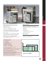

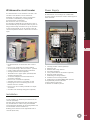
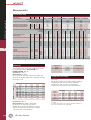
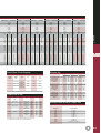
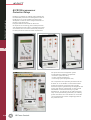
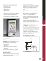

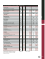
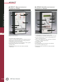
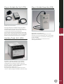
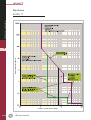
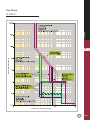
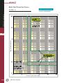
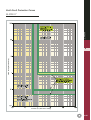
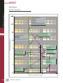
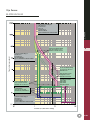
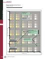
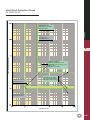
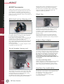


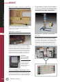


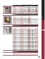
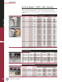


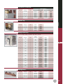
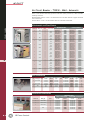

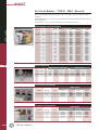
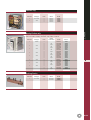


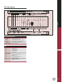
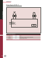
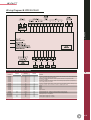
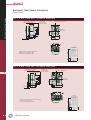

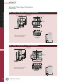
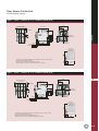
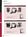
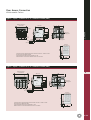
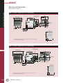

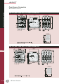

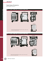


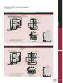
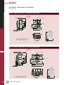

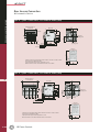
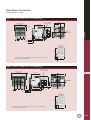


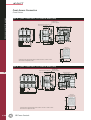

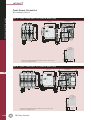

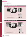


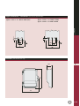


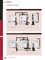
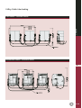
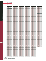
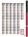


![デジタル信号発生器[3410]](http://vs1.manualzilla.com/store/data/006665977_2-28a3a4836a75699eff9de815a5b714ba-150x150.png)