1
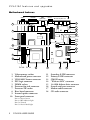
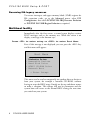
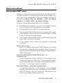
PCL5100 MOTHERBOARD
Pentium® and Pentium®MMX processor ready
USER GUIDE
Intel and Pentium® and Pentium®MMX are registered trademarks of Intel
Corporation.
Information contained in this document is subject to change without notice
and does not represent a commitment on the part of Mitsubishi Electric.
http://www.mitsubishi-computers.com
FEATURES AND UPGRADES
This chapter describes the features of the PCL5100 motherboard
and gives step-by-step instructions for adding more system or video
memory, upgrading the processor, and replacing the configuration
battery. Details of all relevant motherboard connectors and jumper
settings are included.
This motherboard and all its components extremely sensitive to
static electricity. Observe strict antistatic precautions at all times
when handling the board, or any components that you are removing
or fitting to it.
CAUTION
Do not alter any jumpers or switch settings other than those identified
here, unless told to by your Mitsubishi Electric PC supplier or an
authorised maintainer. Otherwise, you may damage the system
processor, the motherboard, or both.
NOTE
After you have upgraded the computer, it may not at first recognise the
new configuration. Start the BIOS Setup utility, go to the Advanced
menu and change the Reset Configuration Data item to “Yes”, then
restart the computer.
PCL5100 USER GUIDE
1
PCL5100 features and upgrades
Motherboard features
Parallel
Video
USB
(optional)
Com 1
Mouse Key/Bd Out
In
18
1
17
16
2
15
14
PL11
3
PL4
PL3
13
4
12
PL19
11
5
6
PL201
PL 202
1
2
3
4
5
6
7
8
9
10
PL 18
Video memory sockets
Motherboard power connector
VESA/AMC feature connector
PSU logic connector
DIMM sockets
Processor fan-sink connector
Processor ZIF socket
Riser board connector
Internal speaker connector
Front panel connector
Pins 1-2 Power button
Pins 3-4 HD indicator light
Pins 5-6 Unused
Pins 7-8 Power Mode light
2
7
PCL5100 USER GUIDE
8
11
12
13
14
15
16
17
18
9
10
Secondary E-IDE connector
Primary E-IDE connector
CMOS battery
“Wake on LAN” connector
1.44 Mb diskette drive connector
Second serial port connector
Modem audio connector
CD audio connector
PCL5100 features and upgrades
Motherboard jumper settings
There are only a few jumpers on the motherboard that you may
need to alter. All others are set at the factory and should not be
changed.
On the motherboard, pin 1 of each jumper block is indicated by a
small triangular marking.
Processor voltage and bus speed (PL19, PL18)
CAUTION
Do not change these jumpers unless you have upgraded the processor. If
they are set incorrectly the processor and other vital motherboard
components could be destroyed.
The BF0 and BF1 jumpers on jumper block PL19 may be fitted in
the High (“1”) or Low (“0”) position; the FS, PW2, PW1 and
PW0 jumpers may simply be either fitted across both pins (“In”) or
not (“Out”). See the table on the next page for the correct
configurations.
PL19
PL 18
For Pentium processors only, two jumpers must also be fitted on
PL18. These jumpers must not be fitted for Pentium/MMX
processors.
PCL5100 USER GUIDE
3
PCL5100 features and upgrades
Processor
Speed
Jumper block PL19
BF1
BF0
FS
PW2 PW1 PW0
Pentium
Pentium
Pentium
Pentium
Pentium
Pentium
Pentium
Pentium/MMX
Pentium/MMX
Pentium/MMX
90 MHz
100 MHz
120 MHz
133 MHz
150 MHz
166 MHz
200 MHz
166 MHz
200 MHz
233 MHz
High
High
High
High
Low
Low
Low
Low
Low
High
High
High
Low
Low
Low
Low
High
Low
High
High
In
Out
In
Out
In
Out
Out
Out
Out
Out
In
In
In
In
In
In
In
Out
Out
Out
In
In
In
In
In
In
In
Out
Out
Out
In
In
In
In
In
In
In
Out
Out
Out
On-board video disabling (PL19)
If you install a video adapter expansion card, the computer should
automatically detect this and disable the on-board video adapter. If
for some reason this does not happen, and you experience problems
with a newly-fitted card, you can manually disable the on-board
video adapter by removing the VGA jumper from jumper block
PL19.
Audio disabling (PL19)
The on-board audio system can be disabled by removing the AUD
jumper from jumper block PL19. Disabling the audio system frees
the interrupt and DMA channel used by that system (normally
IRQ5 and DMA1).
4
PCL5100 USER GUIDE
PCL5100 features and upgrades
BIOS upgrade and recovery (PL11, PL3)
These jumpers should not normally be changed except by a service
engineer or at the direction of a service engineer.
CMOS is cleared by moving the PL11 jumper to the 2-3 position
for a few moments while the system is turned off, then returning it
to the normal 1-2 position.
Clearing CMOS
PL11
CMOS battery connected (default)
1-2
CMOS battery disconnected
2-3
BIOS reprogramming
PL3
Enabled (default)
1-2 (PROG)
Disabled
2-3 (DIS)
Power Mode light colour (PL201)
Normally, the Power Mode light is [red] when the system is in Off
mode. If you move the jumper on block PL201 to pins 2-3 (OFF)
the light is extinguished in Off mode.
PCL5100 USER GUIDE
5
PCL5100 features and upgrades
Motherboard IRQs and DMA channels
Components
Interrupts (IRQs)
0
1
2
3
4
5
6
7
8
9
10
11
12
13
14
15
System timer
Keyboard controller
PIC daisy chain
Serial port 2
BS
Serial port 1
BS
Audio
JS
Diskette controller
BS
Parallel port
BS
Real time clock
On-board video
JS
USB
BS
Mouse
BS
Co-processor
Primary E-IDE
BS
Secondary E-IDE
BS
Components
DMA channels
0
Audio
JS
Diskette controller
BS
Parallel port (ECP)
BS
1
2
3
4
5
6
DMAC daisy chain
Fixed assignment
Usual assignment
BS = Can be disabled by BIOS Setup
6
BIOS alternative
JS = Can be disabled by moving a jumper
PCL5100 USER GUIDE
PnP alternative
7
PCL5100 features and upgrades
Adding more memory
You can give your PC more memory by adding or replacing
memory modules called “DIMMs”.
The motherboard’s two DIMM sockets accept DIMMs of up to
128 Mbytes in any combination (giving a maximum memory
capacity of 256 Mbytes).
IMPORTANT
The DIMMs you use must have the following specification: gold
contacts, 3.3V, 64-bit, unbuffered, either SDRAM-type with Serial
Presence Detect (SPD) and a CAS latency of 2 at 66 MHz or else
EDO-type with 60 ns timing. If you use any other type of DIMM you
risk damaging the motherboard.
Fitting and removing DIMMs
Before you begin
1.
Turn off the computer and unplug all power cords.
2.
Take suitable anti-static precautions and remove the system
covers. Take suitable antistatic precautions at all times while
the motherboard is exposed.
3.
Remove any expansion cards that impede access to the DIMM
sockets.
To install a DIMM
1.
Take the DIMM out of its anti-static packaging. Hold it by its
ends and avoid touching the metal contacts.
2.
Align the DIMM with the chosen socket, ensuring that the
socket end clips are not obstructing.
◊ The indents along the connector edge are asymmetrical to
prevent the DIMM being fitted into the socket the wrong
way round.
PCL5100 USER GUIDE
7
PCL5100 features and upgrades
3.
Pushing gently on its top corners, press the DIMM into the
socket and make sure the two end clips snap into place. Do not
use excessive force. If the module will not fit easily, remove it
and start again.
To remove a DIMM
1.
Press the tabs on both of the socket’s end clips at the same
time. This will release the DIMM and lift it partly out of the
socket.
2.
Pull the DIMM clear of the socket. Hold the DIMM by its
ends and avoid touching the metal contacts.
3.
Place the DIMM in suitable anti-static packaging.
When you have finished, replace any expansion cards you needed to
remove, then refit the system unit panels.
If the computer does not automatically detect the new memory the
first time you turn it on, start the BIOS Setup utility, go to the
Advanced menu and change the Reset Configuration Data item to
“Yes”, then restart the computer. If an error message appears, check
that the DIMMs are of the correct type and are seated correctly in
their sockets.
8
PCL5100 USER GUIDE
PCL5100 features and upgrades
Adding more video memory
Video memory is memory reserved for use by the on-board video
controller. More video memory can provide more colours or higher
resolutions to an extent determined by the capabilities of your
monitor.
If your computer has 1 Mbyte of video memory, you can upgrade it
to the maximum of 2 Mbytes.
To add video memory
1.
Turn off the computer and unplug all power cords.
2.
Take suitable anti-static precautions and remove the system
covers. Take suitable antistatic precautions at all times while
the motherboard is exposed.
3.
Remove any expansion cards that impede access to the video
memory upgrade sockets (see the motherboard diagram at the
start of this chapter).
4.
Unpack the upgrade kit and lay the memory chips out on an
antistatic surface. Hold each chip by its edges and be careful
not to touch the metal pins.
5.
One by one, insert the chips in the sockets.
◊ It is important that the chips are fitted the right way
round. Some chips have a single bevelled edge at one end.
Others have a small semicircular notch at one end and a
bevel at one corner. In either case, the bevelled or notched
end must be aligned with the bevelled corner on the socket
itself.
6.
Replace any expansion cards you removed earlier and refit the
system covers.
If the computer does not automatically detect the new memory the
first time you turn it on, start the BIOS Setup utility, go to the
Advanced menu and change the Reset Configuration Data item to
“Yes”, then restart the computer.
PCL5100 USER GUIDE
9
PCL5100 features and upgrades
Upgrading the processor
The ZIF socket is designed to accept Pentium® processors (see the
table earlier in this chapter). You may wish to upgrade your
processor by replacing it with one of higher performance.
Read the following instructions carefully before starting work.
Changing the processor
1.
Turn off the computer and unplug all power cords.
2.
Take suitable anti-static precautions and remove the system
covers. Take suitable antistatic precautions at all times while
the motherboard is exposed.
3.
Remove any expansion cards that impede access to the
processor.
4.
If the system was in use immediately before starting this
procedure, the processor will be hot; wait at least 15 minutes
for it to cool down.
WARNING
The processor, its fan-sink, if one is fitted, (combined fan and heat
sink), and some of its neighbouring components can get very hot. You
may burn your fingers if you attempt to remove the processor before it
has cooled down.
10
6.
Unplug the power cable of the processor’s fan-sink from the
motherboard. Note where the cable plugs in because you may
need to re-attach it later.
7.
Unclip the fan-sink’s retention clip from the ZIF socket at the
front and the back.
8.
Release the lever from the side of the ZIF socket and raise it to
the upright position (at right-angles to the motherboard).
There may be a little stiffness at the beginning and end of the
lever’s movement; be careful not to use excessive force.
9.
Lift the processor (with fan-sink) clear of the system unit and
place it on an anti-static surface. Hold the processor by its
edges and avoid touching any of the metal pins.
PCL5100 USER GUIDE
PCL5100 features and upgrades
10. Separate the fan-sink from the processor by twisting the fansink from side to side to loosen the grip of the thermal
bonding compound, then slide the fan-sink off to one side of
the processor.
WARNING
When you remove the fan-sink there will be a residual deposit of
thermal bonding compound on the bottom of the fan-sink and the top of
the processor. This compound can cause skin irritation and stain
clothing. Avoid prolonged or repeated contact with skin. Wash your
hands thoroughly with soap and water after handling. Avoid contact
with eyes and inhalation of fumes. Do not ingest.
11. If you are replacing a Pentium processor with a
Pentium/MMX processor, you must remove the two jumpers
from jumper block PL18 (next to the socket). Use the
illustration at the start of this chapter to locate this jumper
block.
12. Ensure that the securing lever on the ZIF socket is still in the
upright position.
13. Take the upgrade processor out of its anti-static packaging.
Hold the processor by its edges and avoid touching the metal
pins.
◊ The processor and the ZIF socket are keyed to ensure that
the processor is installed in the correct orientation. (The
pin pattern is totally different at one corner.) It will only fit
into the socket one way.
14. Place the processor in the socket, making sure that it is
correctly aligned and that you do not bend or otherwise
damage the pins.
◊ If the processor is not big enough to occupy the entire
socket it should be positioned centrally.
CAUTION
If the processor is misaligned it will not go into the socket, and any
attempt to force it will damage the processor, the socket or both.
PCL5100 USER GUIDE
11
PCL5100 features and upgrades
15. Move the securing lever to the locked position. Apply just
enough pressure to overcome the resistance offered by the
lever.
16. Reposition the fan-sink on top of the new processor.
◊ You may have either of two different types of fan-sink.
Note that the larger fan-sink overhangs the socket at one
side.
1
2
1
2
17. Re-fasten the fan-sink’s retention clip to the front and back of
the ZIF socket.
12
PCL5100 USER GUIDE
PCL5100 features and upgrades
18. Reconnect the fan-sink’s power cable to the motherboard. It
goes on the connector labelled FAN 2 or PL200 as shown on
the motherboard diagram.
CAUTION
If the fan-sink power cable is not reconnected properly the processor may
overheat and be permanently damaged.
19. Adjust the processor voltage and bus speed selection jumpers
in block PL19 as described at the start of this chapter.
When you have finished, replace any expansion cards you needed to
remove, then refit the system covers.
Replacing the configuration battery
The computer keeps a record of its current hardware configuration
in a CMOS memory chip which is sustained by a small battery.
This battery has a life of up to 5 years. If you find that you have to
reconfigure the computer every time you turn it on, the battery is
probably failing and needs to be replaced.
The battery is a 3 volt lithium type (CR2032 or equivalent)
typically used in calculators and other small, battery-powered
electronic items.
PCL5100 USER GUIDE
13
PCL5100 features and upgrades
To replace the battery
1.
Turn off the computer and unplug all power cords.
2.
Take suitable anti-static precautions and remove the system
covers. Take suitable antistatic precautions at all times while
the motherboard is exposed.
3.
Remove any expansion cards or drives that may impede access
to the battery.
4.
Using a non-conductive implement, release the latch that
holds the battery in place. The battery will pop up allowing
you to lift it out of the holder.
WARNING
You must not use a metal or other conductive implement to remove the
battery. If a short-circuit is accidentally made between the battery’s
positive and negative terminals, the battery may explode.
5.
Check that the replacement battery looks the same as the
battery you have removed.
6.
Taking care not to touch the top or bottom surface of the
battery, pick up the replacement with the positive (+) terminal
upwards. Press the battery into the holder using a nonconductive implement.
7.
Refit any cards or drives in their original places that had to be
removed in step 3, and then refit the system covers.
8.
Dispose of the discharged battery in accordance with the
battery manufacturer’s instructions.
The next time you turn on the computer you will have to run the
BIOS Setup utility to reset the hardware configuration.
14
PCL5100 USER GUIDE
BIOS SETUP & POST
BIOS (pronounced “bye-oss”) stands for ‘basic input/output
system’. The BIOS mediates between the computer’s hardware –
the processor, memory, and so on – and its software – the operating
system and your programs. The BIOS program is kept in
permanent, read-only memory or ROM (although if necessary it
can be upgraded by an authorised maintainer).
BIOS Setup is a helpful utility that forms part of the BIOS
program. It allows you to view and alter the computer’s hardware
configuration. It is also used to configure various security and
power-saving options. Configuring the computer is necessary to
ensure that the software you use can recognise and exploit the
hardware’s capabilities.
The current configuration is kept in a special area of memory, called
CMOS memory, and maintained by a battery so that the
configuration is preserved even while the computer is switched off.
Whenever the computer is turned on, the BIOS power-on self-test
(POST) routine tests various hardware components, including
memory, and compares the actual configuration of the computer
with that recorded in permanent (CMOS) memory.
A configuration discrepancy could arise if you have just installed or
removed a hardware option (for example, if you have added or
replaced memory). In this case you may be diverted directly into the
BIOS Setup utility.
PCL5100 USER GUIDE
1
PCL5100 BIOS Setup & POST
BIOS Setup
To start the BIOS Setup utility:
1.
Turn on or restart your computer.
2.
Wait until the Mitsubishi Electric logo appears on the screen.
3.
Press the F2 key.
4.
If you have previously defined a Supervisor password, you are
prompted for it before BIOS Setup starts.
If BIOS Setup starts on its own
BIOS Setup might start on its own for three reasons:
♦
The power-on self-test (POST) detects a configuration error or
fault. This may be signalled by one or more POST error
messages. If a persistent fault is indicated, make a note of any
error messages and the current configuration settings before
calling an authorised maintainer.
♦
The CMOS battery may be running down. This may cause
spurious POST error messages. If this happens every time you
turn on the computer, you may have to change the battery.
♦
The computer’s configuration may have changed, for example
by the addition of more system memory or an expansion card.
In this case you may have to define the new configuration.
Control keys
Use the keys listed in the legend bar at the bottom of the BIOS
Setup screen to make your selections or exit the current menu.
Sub-menus are marked by a pointer. To display a sub-menu, use
the arrow keys to move the cursor to the sub-menu you want, then
press ENTER.
2
PCL5100 USER GUIDE
PCL5100 BIOS Setup & POST
Changeable fields are enclosed in square brackets. To select an item,
use the arrow keys to move the cursor to the field you want. Then
use the PLUS (+) and MINUS (–) keys to select a value for that field.
Press
To
F1
View a general help topic. Press ESC to close
the help window.
or ALT-H
ESC
Exit the current menu.
LEFT or RIGHT arrow
Select a different menu.
UP or DOWN arrow
Select fields on the current menu.
PLUS (+)
Select the next value for the current field.
or F6 or SPACEBAR
MINUS (-)
or F5
Select the previous value for the current
field.
ENTER
Make a selection from the menu bar or
enter a sub-menu.
HOME or END
Move the cursor to the top or bottom of
the current menu.
PAGE UP or PAGE DOWN
Move the cursor to the next or previous
page of the current menu.
F9
Restore the default settings for the fields on
the current menu.
F10
Save the changes you’ve made and exit
from BIOS Setup.
CAUTION
The default BIOS settings may not be appropriate for your particular
system. Make a note of the current settings before pressing F9 or using
the Load Setup Defaults option of the Exit menu.
Getting help in BIOS Setup
You can at any time get general help about the control keys by
pressing the F1 key.
The help window on the right-hand side of each menu displays help
text for the currently-selected field. It changes as you move the
cursor from one field to another.
PCL5100 USER GUIDE
3
PCL5100 BIOS Setup & POST
Reserving ISA legacy resources
To reserve interrupts and upper memory block (UMB) regions for
ISA expansion cards, go to the Advanced menu, select PCI
Configuration, then select PCI/PNP ISA IRQ Resource Exclusion
or PCI/PNP ISA UMB Region Exclusion as required.
Multi-boot facility
Immediately after the first screen, a second screen displays various
POST messages such as the memory test. While this screen is on
display, a message at the bottom says:
Press <F2> to enter setup or <ESC> to enter Boot Menu
Even if this message is not displayed, you can press the <ESC> key
and this menu will appear:
Boot Menu
1.
2.
3.
4.
5.
Diskette Drive
Removable Devices
Hard Disk Drive
ATAPI CD-ROM Drive
Network Boot
< Enter Setup>
This menu can be used to temporarily use another drive or device to
boot your system, for example a bootable CD-ROM, without
having to enter the BIOS setup. Simply use the up and down arrows
to make a selection. This change will not be permanent and the
system boot will revert to the normal BIOS setting the next time
you switch on your system.
4
PCL5100 USER GUIDE
PCL5100 BIOS Setup & POST
Power-on self-test
Recoverable POST errors
Whenever a recoverable (non-terminal) error occurs during POST,
the BIOS displays an error message describing the problem (the
most usual are described below). After some messages, you may be
prompted to Press <F1> to resume, <F2> to enter
Setup or just Press <F2> to enter Setup.
In general, you should respond to these errors as follows:
♦
Shut down the computer, wait 20 to 30 seconds, and then
turn it on again to see if the problem is still reported.
♦
Check that all external cables are securely connected.
♦
Try running the BIOS Setup utility to reconfigure the system.
If the computer won’t start after you make changes in BIOS
Setup, try restoring the original values.
♦
Open up the system unit and check that all internal signal and
power cables are securely connected.
♦
If the problem persists, contact your supplier or authorised
maintainer.
Diskette drive A error
Drive A: is present but fails the POST diskette tests. Check
that the drive is defined correctly in BIOS Setup. If necessary,
open the system unit and check that the drive’s signal (ribbon)
cable is connected.
System/Extended/Shadow RAM failed at offset: xxxx
Failing bits: yyyy
System, extended or shadow memory is not working, or not
configured properly, at offset xxxx. The hexadecimal number
yyyy is a map of the bits at the address which failed the memory
test. Each “1” in the map represents a failed bit.
Fixed disk X failure or Fixed disk controller failure
A fixed (hard) disk drive is not working or not configured
properly. Check that the drive is defined correctly in BIOS
Setup. If necessary, open the system unit and check that the
drive’s signal (ribbon) cable is connected.
PCL5100 USER GUIDE
5
PCL5100 BIOS Setup & POST
Incorrect drive A type - run SETUP
The diskette drive is not correctly specified in BIOS Setup.
Invalid NVRAM media type
Problem with NVRAM (non-volatile random-access memory).
Keyboard error [nn] or Keyboard controller error
There is a problem with the keyboard or (less likely) the
standard I/O controller on the motherboard. If POST
discovers a stuck key it displays its scan code.
Operating system not found
An operating system cannot be located either on a system
diskette or on a hard disk. Start BIOS Setup and check that
the diskette and/or hard disk drives are specified correctly.
Parity check 1 xxxx or Parity check 2 xxxx
Parity error found on the system (1) or I/O (2) bus. The BIOS
attempts to locate and display the address xxxx. If it cannot
locate the address, it displays “????”.
Previous boot incomplete - default configuration used
The previous POST did not complete successfully. POST
loads default values and offers to start BIOS Setup. If the
failure was caused by incorrect values and they are not
corrected, the next boot will likely fail too.
Real-time clock error
Enter BIOS setup and check the System Time and System
Date settings on the Main menu.
System battery is dead - replace and run Setup
Replace the configuration battery as instructed in the
Motherboard Features & Upgrades chapter, then use BIOS
Setup to reconfigure the system.
System cache error - cache disabled
The RAM cache failed POST and BIOS disabled it.
System CMOS checksum bad - run Setup
System CMOS has been corrupted or modified incorrectly,
perhaps by an application program that changes data stored in
CMOS. Run BIOS Setup and reconfigure the system either by
getting the default values or by making your own selections.
6
PCL5100 USER GUIDE
PCL5100 BIOS Setup & POST
Terminal POST errors and beep codes
There are several POST routines that shut down the computer if
they fail. If possible, the BIOS displays a two-digit hexadecimal
code and/or sounds a sequence of beeps to identify the point at
which POST failed. The most usual errors are listed below.
The BIOS also issues one long tone followed by two short tones if
the video system is faulty or if an external ROM module (including
video ROM) fails.
Turn off the computer for 30 seconds and then try again. If the
fault persists, make a note of the error code (if any) and call your
supplier or authorised maintainer.
Code
Beeps
Test which failed
16
1-2-2-3
BIOS ROM checksum
20
1-3-1-1
DRAM refresh.
22
1-3-1-3
8742 keyboard controller
2C xxxx
1-3-4-1
RAM failure on address line xxxx.
2E xxxx
1-3-4-3
RAM failure on data bits xxxx of low byte of memory bus.
30 xxxx
1-4-1-1
RAM failure on data bits xxxx of high byte of memory bus.
46
2-1-2-3
Check ROM copyright notice
58
2-2-3-1
Test for unexpected interrupts
98
1-2
Video configuration failure, or option ROM checksum
failure. (One long, two short beeps.)
PCL5100 USER GUIDE
7
http://www.mitsubishi-computers.com
MITSUBISHI ELECTRIC
PC DIVISION
Apricot Computers Limited
3500 Parkside
Birmingham Business Park
Birmingham B37 7YS
United Kingdom
MITSUBISHI ELECTRIC
PC DIVISION
Apricot Computers Limited
Niederlassung Deutschland
Gothaer Strasse 27
40880 Ratingen
Germany
Tel +44 (0) 121 717 7171
Fax +44 (0) 121 717 7799
Tel +49 (0) 2102 4556
Fax +49 (0) 2102 455700