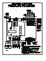
1
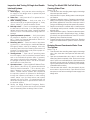
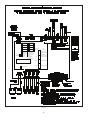
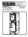
Bulletin 740 Rev. B
Instructions for
Installation, Operation,
Care and Maintenance
Single Interlock
Double Interlock
10 PSI (0,7 bar) Pneumatic Supervising Pressure
The Reliable Automatic Sprinkler Co., Inc., 103 Fairview Park Drive, Elmsford, New York 10523
Bulletin 740 Rev. B
Model DDX PrePaK, Type D
Preaction System
2”(50mm), 21/2” (65mm) &
3”(80mm) Sizes
General Description
The Reliable Model DDX 2” (50 mm), 2½” (65 mm) and 3” (80
mm) PrePaKs are completely self-contained, supervised preaction systems that can be readily installed within a floor space
of 4.5 ft2 (0.42 m2) (not including door swing). Installation of the
PrePaK (not including exterior devices, i.e., detectors and alarm
bells), requires just three piping connections: a 2” (50 mm), 2½”
(65 mm) or 3” (80 mm) supply line, a 2” (50 mm), 2½” (65 mm) or
3” (80 mm) system line, and a 1” (32 mm) drain line. Reference locations of these piping connections are shown in Fig.1. Also, two
120 / 220 VAC electrical supply connections are required. Note:
The Model DDX PrePak is available with its air compressor and
Potter Model PFC-4410-RC Releasing/Control Panel wired for a
120 VAC / 60Hz or for a 220 VAC / 50 Hz power supply.
The Reliable Model DDX PrePaK contains the following components within its 24” (0.61 m) W x 27” (0.69 m) D x 68” (1.73 m) H
12-gauge steel enclosure:
• One Reliable Model DDX 2” (50 mm), 2½” (65 mm) or
3” (80 mm) Deluge Value with Type D Double Interlock
Preaction Trim set (See Reliable Bulletin 737).
• One Gast Model 1HAB-11T-M100X Hp Air Compressor (2” & 2½” sizes) or one Gast Model 3HEB-13TM345 HP Air Compressor (3” Size.)
• One 2 gallon (9.1 liter) air tank.
• One Potter Model PFC-4410-RC Releasing/Control
Panel (See Potter Manual #5403550).
• One Pressure Maintenance Device for system air supervision (contains regulator, check valve, strainer, and
rapid-fill option).
• All required fittings, gauges, electrical connectors, and
electrical devices to utilize the system in single interlock, single interlock cross-zoned, double interlock,
and double interlock cross-zoned applications.
The Reliable Model DDX PrePaK utilizes the Potter Model PFC4410-RC Releasing Control Panel. This fully programmable, microprocessor-based releasing panel is Underwriters Laboratories, Inc. Listed and is in compliance with NFPA 13 and NFPA 72.
Because the PFC-4410-RC is totally zone and output programmable, the Reliable Model DDX PrePaK can be utilized in many
different preaction applications without having to rewire any of the
factory installed devices. Once the previously described connections are completed, the 24 VDC detectors, output devices, and
relay contacts may be connected to achieve the desired system
implementation.
The Model DDX PrePaK can be used in both single and double
interlock applications. Reliable Single and Double Interlock Preaction Systems are designed for water sensitive areas that require
protection from inadvertent water flow into the sprinkler system
piping.
The major benefits of a single/double interlock preaction System, when compared with a wet pipe system, are as follows:
A. A fire alarm sounds prior to the flow of water from a sprinkler, which may enable extinguishing the fire by handheld
means before the operation of any sprinkler head occurs.
B. An annunciator signals whenever the integrity of piping or
sprinklers is accidentally or intentionally disturbed; however,
no water flow or water damage will result at that time.
C. Speedy detection and an early fire alarm are provided by
fire detectors, without the delay associated with water de-
livery time in the event of a fire. Note that with a wet pipe
system, the fire alarm is delayed until after water has begun
flowing from and operated sprinkler head.
In single interlock applications, one electrical detector senses
the presence of fire, thereby causing the electrical releasing control panel to activate fire alarm devices and energize the solenoid
releasing valve in the open position. Note that arranging detectors in a cross-zoned pattern will require operation of two detectors before the solenoid valve can open (Note: Cross-zoned detection systems are not permitted in New York City and are not
Factory Mutual Approved). The solenoid valve, when closed, is
preserving supply water pressure in the deluge valve’s push-rod
chamber. Actuating the solenoid valve releases that water pressure which allows the valve to open.
To fully operate a single interlock system with cross-zoned
detection, two separate electrical detection systems must activate and a sprinkler must open. During the early stages of a fire,
smoke or heat activates the first detector, which causes the control panel to produce a local alarm and an alarm at the main fire
alarm panel. Electrical relays inside the releasing control panel
can be used to shut down air moving equipment or activate security doors and other electrical devices when the panel goes into
this first condition. Subsequent activation of a second, nearby or
adjacent detector, on a separate detection system, will cause the
panel to energize the solenoid valve open and release water into
the sprinkler piping. Water flowing into the sprinkler piping will simultaneously produce water pressure that causes the transfer of
contacts in the alarm pressure switch mounted in the riser assembly, thereby activating a water flow alarm device. The flow of water
into the sprinkler piping effectively converts the dry system into
a wet pipe system. In the event the fire subsequently produces
sufficient heat to operate a sprinkler head, water will flow from that
sprinkler, controlling the fire.
To flow water into a double interlock preaction system, two
events must take place. A fire detection device must operate,
and a pressure switch must be operated by the loss of system
pressure (sprinkler operation). These two signals, both an electric signal and a pneumatic signal, must coexist at the releasing
control panel, which only then will energize the solenoid releasing
valve, causing water flow into the sprinkler system and out of the
open sprinkler(s).
In the event that the system piping is ruptured or a sprinkler
head is accidentally opened, the system pressure switch will operate and an alarm will sound. The riser assembly, however, will
not release water since the solenoid valve remains closed due to
only one input into the releasing control panel.
When using the Reliable Model DDX PrePaK, in either single or
double interlock applications, the sprinkler system is pressurized
(supervised) with air provided by the air compressor and is monitored by a system pressure switch.
A Model B Hydraulic Manual Emergency Releasing station
is standard equipment in the Model DDX PrePaK. It consists of
an aluminum nameplate mechanically attached to a ball valve.
The valve handle in its OFF position is guarded against accidental turning to the ON position (and system discharge) by a nylon
cable tie provided with the PrePaK assembly. The cable tie is designed to allow, in case of an emergency, forceful turning of the
valve handle to the ON position.
2.
Fig. 1
3.
Approvals
1. Underwriters Laboratories, Inc. Listed and Certified for Canada* (cULus) as an assembled unit in the “Special System
Water Control Valves Assembled Units” category, (VKYL).
2. Factory Mutual (FM) Approved, as PrePak Single Interlock
and Double Interlock Preaction Systems.
* Electrical devices and control panel must be specified to
meet Canadian requirements. This option is available.
3. NYC MEA 258-93-E
Note: Although PrePak units are UL Listed, custom built units
are sometimes supplied upon request. The components within
these special units maintain their individual Listings/Approvals,
whereas the assembled units do not.
PrePak units are also available without their door-mounted Potter PFC-4410-RC Releasing/Control Panel and Air Compressor.
These units will still retain their Listings/Approvals, however the
installing contractor should make sure that any remote controlled
Releasing/Control Panels used with these units are Listed/Approved and programmed to handle the required sequence of
operation necessary to operate the automatic sprinkler system.
Any unauthorized modification or addition made on-site to a
factory-built Listed/Approved unit will void the Listing/Approval.
Such modifications or additions may void the unit’s warranty as
well. Consult Reliable’s Technical Services Department before
proceeding with any such modifications or additions.
The following is a list of Technical Data Bulletins which describe the valves and devices which are used in the system:
Deluge Valve
512/513
Type D Double Interlock Preaction Trim
737
Low Air Pressure Switch
System Sensor, A05-0176
Hydraulic Emergency Station (Model A)
506
Mechanical Sprinkler Alarm
612/613
Solenoid Valve
718
Alarm Pressure switch
System Sensor, A05-0176
Control Panel
Potter Manual #5403550
Detectors
722
Fire Alarm Devices
700
The following table provides a quick reference to various programs (found in this bulletin and the Potter Manual #5403550) that
may be utilized with a Model DDX PrePaK:
Technical Data
1. The Reliable Model DDX 2” (50 mm), 2½” (65 mm) and 3”
(80 mm) PrePaKs are rated for a minimum supply pressure
of 20 psi (1,4 bar) and a maximum supply pressure of 250
psi (17,2 bar). Note: 1 bar = 100 kPa.
2. Friction loss, expressed in equivalent length of Schedule 40
pipe and based on Hazen-Williams Formula with C=120
and a flowing velocity of 15 ft/s (4.6 m/s), is:
Valve Size
Equivalent Length
2” (50mm)
4.4’ (1.3 m)
2.5” (65mm)
6.0’ (1.8 m)
3” (80mm)
12.6’ (3.8 m)
(2)
Groove
Diameter
2” (50 mm)
2.375”
(60 mm)
2.250”
(57 mm)
2.5” (65 mm)
2.875”
(73 mm)
2.720”
(69 mm)
3” (80 mm)
3.500”
(89 mm)
3.344”
(85 mm)
Groove
Width
5/16”
(8 mm)
Single Interlock
Single Hazard, 2 Alarm Zones
with 1 Waterflow Zone and 2
Supervisory Zones
Single Interlock,
Cross-Zoned
Single Hazard, Cross-Zoned, 2
Alarm Zones with 1 waterflow
Zone and 2 Supervisory Zones
Potter
Program
#7(2)
Double Interlock
Single Hazard, 2 Alarm Zones
with 1 Waterflow Zone and 1
Supervisory Zone
Potter
Program #9
Program
No.
Potter
Program #6
Custom
Program #1
(NYC)
Factory Program setting
System Design Considerations
The automatic sprinklers, releasing devices, fire detection devices, manual pull stations, and signaling devices which are utilized with the Reliable Model DDX 2” (50 mm), 2½” (65 mm) and
3” (80 mm) PrePaKs must be UL and/or ULC Listed or FM Approved, as applicable.
The steel enclosure and all the interconnecting piping must be
located indoors in a readily visible and accessible location and in
an area that can be maintained at a minimum temperature of 40°F
(4°C). Note: Heat tracing is not permitted. The solenoid valve
is operated and supervised by the Potter Model PFC-4410-RC
Releasing Control Panel. Details on the electrical connections of
this system to the Potter Panel can be found in the Potter Manual
#5403550, Installation, Operation and Instruction of PFC-4410RC Releasing Control Panel (this manual is included with other
pertinent manuals and shipped inside the enclosure). This panel
is fully zone and output programmable and may be adapted to
several applications.
Groove Dimensions
Outlet
Diameter
Description
(1)
Refer to Potter Manual # 5403550 included with the PrePak, for other
programming options available.
These values account for the Model DDX Deluge Valve,
supply manifold tee, butterfly control valve, and small pipe/
manifold located directly above Model DDX Deluge Valve.
2” (50 mm), 2½” (65 mm)
3. Shipping Weight:
& 3” (80 mm) - 554 lb. (251.8 kg)
Dimensions:
2” (50mm) W x 28.9” D x 68” H
(0.61 m W x 0.73 m D x 1.73 m H)
(Refer to Fig. 1 for additional dimensions)
4. Grooved end connections:
• ANSI/AWWA C606 grooved inlet and outlet.
Valve Size
Desired
Applications (1)
Outlet
Face to
Groove
System Supervising Pressure Requirements
In accordance with NFPA 13, when using the Reliable Model
DDX 2” (50 mm), 2½” (65 mm) or 3” (80 mm) PrePaK in double
interlock applications, a minimum of 7 psi (0,5 bar) pneumatic
pressure is required to supervise the sprinkler system. When initially filling the system with air, the enclosure’s door should remain
open in order to provide maximum intake air flow to the air com-
3/8”
(16 mm)
4.
pressor. The air compressor is connected to an 2 gallon (9.1 liter)
ASME rated storage tank. This tank functions as a reservoir, providing make-up air to compensate for small, intermittent leaks in
the sprinkler system. It should be noted that significant leaks may
overburden this storage tank, thereby causing the air compressor
to continuously cycle on and off.
The Pressure Maintenance Device supplied with the system (refer to Fig. 8), is factory set to maintain system pneumatic pressure
at approximately 10 psi (0,7 bar). Readjusting system pressure to
approximately 10 psi (0,7 bar), if necessary, is accomplished by
first loosening the locknut on the air pressure regulator and turning the adjustment screw (refer to Fig. 8). The system air pressure
gauge that is included in the trim may be used to verify the correct level of pneumatic pressure.
The system air pressure switch (refer to Fig. 8) is factory set
to operate between 8 psi and 4 psi (0,6 bar and 0,3 bar) with
decreasing pressure. Adjustment, if required, should be made
according to System Sensor Bulletin A05-0176 included with the
switch.
System Operation (Single Interlock)
To fully activate (water flow) the Reliable Model DDX 2” (50 mm),
2½” (65 mm) or 3” (80 mm) PrePaK in a single interlock application, a fire detection device (smoke, heat, etc.) (two detectors with
cross-zoned detection) must activate. Subsequently, a sprinkler
head must open to discharge water on the fire.
When the single interlock preaction system is set for service, the
supply pressure acts both on the underside of the deluge valve’s
clapper and on the valve’s push rod by means of the pressurized
push rod chamber. The pressure force acting on the push rod,
when utilized with the mechanical advantage of the deluge valve’s
lever, is more than sufficient to hold the clapper in the closed position against the water supply pressure.
Energizing the releasing solenoid valve allows the deluge valve’s
push-rod chamber to be vented to drain through its outlet. Since
the pressure cannot be replenished through the inlet restriction
as rapidly as it is vented though the outlet, the push-rod chamber pressure falls rapidly. When the push-rod chamber pressure
drops below one-third of the supply pressure, the opening force
acting beneath the clapper becomes greater than the push-rod
force acting on the lever. This causes the clapper to open. Refer
to Reliable Bulletins 512 and 513 for further details.
Once the clapper has opened, the lever acts as a latch, preventing the clapper from returning to the closed position. Water from
the supply flows through the deluge valve into the system piping.
Water also flows through the deluge valve alarm outlet to activate
any water flow alarm devices. Note that the solenoid valve will be
maintained open by the Potter Model PFC-4410-RC Releasing
Control Panel’s latching feature until it is reset for operation.
After system shutdown and draining, the Model DDX Deluge
Valve is easily reset without special tools (see Fig.8). Restore detection devices by resetting or replacing any operated device.
Once detection devices are restored, (the Potter Model PFC4410-RC Releasing Control Panel reset), and supply pressure is
re-supplied to the push-rod chamber, the deluge valve is reset.
System Electrical Requirements
All releasing, alarm, and detection devices in the Reliable Model DDX 2” (50 mm), 2½” (65 mm) and 3” (80 mm) PrePaKs are
supervised by a Potter Model PFC-4410-RC Releasing Control
Panel. To utilize one of the doors of the steel enclosure as a mount
for the releasing control panel, all of the terminals are translated
to two, water-tight terminal boxes mounted on the interior of the
enclosure. Note: the EOL (End of Line) resistors have also been
relocated. It is from these terminal boxes that all field wiring is connected. There is one terminal box that contains the 24 VDC connections and one that contains the 120 / 220 VAC connections.
The Reliable Model DDX PrePaK is delivered with five factory-installed electrical devices. They consist of the following:
1. A system air pressure switch, which is used to monitor
sprinkler piping.
2. An alarm pressure switch, which indicates an actuation of
the deluge valve.
3. A normally-closed, releasing solenoid valve, which is used
to actuate the deluge valve.
4. A HP ( HP for 3” size) tank-mounted air compressor with 2
gallon (9.1 liter) tank.
5. A supervised butterfly water control valve.
The factory electrical connections of these devices are illustrated
in Fig. 4. For information on how to install fire detection devices to
initiating Zones 1 and 2 of the Potter Model PFC-4410-RC Releasing Control Panel, refer to Fig. 5 or Fig. 6. For information on how
to install output devices, i.e., alarm bells or trouble annunciators,
to the Potter Model PFC-4410-RC Releasing Control Panel, refer
to Fig. 7. The power supply, standby emergency power supply,
battery charger and rectifier circuitry are all contained within the
PFC-4410-RC panel. Batteries that provide 90 hours of standby
power are provided with the panel. For additional information
and detailed wiring diagrams, refer to Potter Manual #5403550,
Installation, Operation and Instruction of PFC-4410-RC Releasing
Control Panel.
Caution: Repairs or disassembly of the solenoid valve should
only be done by a trained technician. An improperly repaired or
partially assembled solenoid valve could result in failure of the
valve to operate.
System Operation (Double Interlock)
To fully activate (water flow) the Reliable Model DDX 2” (50 mm),
2½” (65 mm) or 3” (80 mm) PrePaK in a double interlock application, two independent events must coexist. An electrical fire
detection device (smoke, heat, etc.) and the system air pressure
switch must be activated. This pressure switch is activated by a
reduction of the system’s pneumatic pressure (as a result of sprinkler operation). Both of these events will cause the control panel
to energize the solenoid valve, thereby releasing water through
the deluge valve and into the sprinkler system. The initiation of
either one of these events will only cause an alarm to annunciate,
and will not fill the sprinkler system.
When the double interlock preaction system is set for service,
the supply pressure acts both on the underside of the deluge
valve’s clapper and on the valve’s push rod by means of the pressurized push rod chamber. The pressure force acting on the push
rod, when utilized with the mechanical advantage of the deluge
valve’s lever, is more than sufficient to hold the clapper in the
closed position against the water supply pressure.
5.
Energizing the releasing solenoid valve allows the deluge valve’s
push-rod chamber to be vented to drain through its outlet. Since
the pressure cannot be replenished through the inlet restriction
as rapidly as it is vented though the outlet, the push-rod chamber pressure falls rapidly. When the push-rod chamber pressure
drops below one-third of the supply pressure, the opening force
acting beneath the clapper becomes greater than the push-rod
force acting on the lever. This causes the clapper to open. Refer
to Reliable Bulletins 512 and 513 for further details.
Once the clapper has opened, the lever acts as a latch, preventing the clapper from returning to the closed position. Water from
the supply flows through the deluge valve into the system piping.
Water also flows through the deluge valve alarm outlet to activate
any water flow alarm devices. Note that the solenoid valve will be
maintained open by the Potter Model PFC-4410-RC Releasing
Control Panel’s latching feature until it is reset for operation.
After system shutdown and draining, the Model DDX Deluge
Valve is easily reset without special tools (see Fig.8). Restore detection devices by resetting or replacing any operated device.
Once detection devices are restored, (the Potter Model PFC4410-RC Releasing Control Panel reset), and supply pressure is
re-supplied to the push-rod chamber, the deluge valve is reset.
Resetting Single And Double Interlock Systems
Refer to Fig. 8.
1. Close the main valve controlling water supply to the deluge
valve and close the ¼” air shutoff valve, valve J.
2. Close the pushrod chamber supply valve, valve A.
3. Open the main drain valve, valve B, and drain system.
4. Open all drain valves and vents at low points throughout
the system, closing them when flow of water has stopped.
Open valve D. Note: The above steps accomplish the
relieving of pressure in the pushrod chamber of the deluge
valve.
5. Push in the plunger of ball drip valve, valve F, to force the
ball from its seat, and drain any water in the alarm line.
6. With the Model B Manual Emergency Station, valve D,
open, push in and rotate the deluge valve’s external reset
knob clockwise until you hear a distinct clicking noise, indicating that the clapper has closed. Note: The reset knob
can be rotated only after pressure in the pushrod chamber
is reduced to atmospheric conditions (0 psig).
7. Inspect and replace any portion of the sprinkler system
subjected to fire conditions.
8. Verify that the following valves are in their respective positions:
valve C – open, valve E – closed, valve H – closed,
valve K – open, valve M – closed.
9. Open valve A and allow water to fill the deluge valve’s pushrod chamber. Close valve D.
10. Bleed any air from the actuation piping by energizing the
solenoid valve. This is done by operating a detector or an
electric manual emergency station. While water is flowing
through the solenoid valve, cause it to close by pressing the
system reset button on the Potter PFC-4410-RC Releasing
Control Panel. Note: All detection devices must be reset
before the releasing/control panel can be reset.
11. Open the ¼” air shutoff valve, valve J, to restore air pressure in the sprinkler system. The rapid air-fill shutoff valve,
valve M, may be opened here to expedite the filling of the
sprinkler system.
12. Open slightly the main valve controlling water supply to
the Model DDX Deluge Valve, closing drain valve B when
water flows. Observe if water leaks through the ball drip
valve, valve F, into the drip cup, G. If no leak occurs, the
deluge valve’s clapper is sealed. Open slowly, and verify
that the main valve controlling water supply is fully opened
and properly monitored.
13. Verify that valve A is open.
14. Secure the handle of the Model B Manual Emergency Station, valve D, in the OFF position with a nylon tie (supplied
with the assembly).
15. Press the system reset button on the Potter PFC-4410-RC
Panel to place the system in the ready condition. Note: All
detection devices must be reset before the panel can be
reset.
Maintenance
The Reliable Model DDX PrePaK and associated equipment
shall periodically be given a thorough inspection and test. NFPA
25, Inspection, Testing and Maintenance of water Based Fire Protection Systems, provides minimum maintenance requirements.
Systems should be tested, operated, cleaned and inspected at
least annually, and parts replaced as required. Periodically open
the air/condensate drain valve (refer to Fig. 8) beneath the air tank
to drain any condensate accumulation. Bulletin 512 provides
information for maintaining the Model DDX Deluge Valve. Potter
Manual #5403550 provides information for maintaining the PFC4410-RC Releasing Control Panel.
6.
RED O UTPUT LED STEADY: ABORT
RUN
PROGRAM
ZONE 1
OUTPUT 1
ZONE 2
OUTPUT 2
ZONE 3
OUTPUT 3
ZONE 4
OUTPUT 4
AC POW ER
S U P 1 /A B O R T
PO W ER TBL
S U P E R V IS O R Y 2
SYSTEM TBL
C O M M O N A LA R M
SUP TBL
GROUND
F A U LT
A L A R M S ILE N C E
STEADY:
D IS C H A R G E D
F L A S H IN G :
P R E -D IS C H A R G E
RUN
MODE
PROGRAM
MODE
S C R O L L -U P
B U Z Z E R S ILE N C E
SET
SELECT
F U N C T IO N
}
LAM P
TEST
S C R O L L -D O W N
B U Z Z E R S ILE N C E
S IG N A L S ILE N C E
SYSTEM RESET
V IE W IN G A N G LE
Fig. 2
7.
Fig. 3
8.
Fig. 4
9.
10.
Fig. 5
11.
Fig. 6
12.
Figure 7 — Wiring Diagram
Inspection And Testing Of Single And Double
Interlock Systems
Testing The Model DDX PrePaK Without
Causing Water Flow
Refer to Fig. 8.
1. Water supply — Verify that the valve controlling water supply to the deluge valve is opened fully and
properly monitored.
2. Alarm line — Verify that valve C is opened and remains in this position.
3. Other trimming valves — Verify that valve A is
open as well as all of the pressure gauge’s ¼” 3-way
valves. Valves D, E, and H should be closed.
4. Ball drip valve F — Push in on the plunger to be sure
the ball check is off its seat. If no water appears, the
deluge valve’s water seat is tight. Inspect the bleed
hole in the front of the Model DDX Deluge Valve for
leakage.
5. System pneumatic pressure — Verify that system
air pressure is between 7 and 10 psi (0,5 bar 0,7
bar). Check the Pressure Maintenance Device for
leakage and proper pressure.
6. Releasing device — Check the outlet of the releasing device (i.e., solenoid valve or the Model B Manual
Emergency Station, valve D) for leakage. Also verify
that tubing drain lines from releasing devices are not
pinched or crushed which could prevent proper releasing of the deluge valve.
7. Testing alarms — Open valve E permitting water
from the supply to flow to the alarm pressure switch
and to the mechanical sprinkler alarm (if present).
After testing, close this valve completely. Push in on
the plunger of ball drip valve F until all of the water
has drained from the alarm line.
8. Operational test — Open the Model B Manual Emergency Station, valve D only, OR, operate the solenoid
valve by electrical actuation. This is done by operating a detector or an electric manual emergency
station. Double interlock systems also require that
the sprinkler system’s air pressure be discharged,
through the inspectors test station or other venting
means, below 4 psi (0,3 bar) before total system
operation will occur. Note: An operational test will
cause the Deluge Valve to open and flow water into
the sprinkler system.
9. Secure the Model B Manual Emergency Station,
valve D, in the OFF position with a nylon tie (included
with the assembly) after the deluge valve is reset.
Refer to Fig. 8.
1. Close the main valve controlling water supply to the deluge
valve and open drain valve B.
2. Verify that valve A is open, allowing water to enter the pushrod chamber.
3. Operate the detection system - Operate a cross-zoned releasing control panel by operating two detectors. For double interlock applications, close valve J and open valve H.
Doing so will discharge the sprinkler system’s air pressure.
4. Step #3 should result in a sudden drop of water pressure
in the deluge valve’s push-rod chamber via an energized
solenoid valve.
5. Reset the detection system - Reverse the detection system
operations performed in Step #3 above. Note: All detection devices must be reset before the Potter PFC-4410-RC
Releasing Control Panel can be reset.
6. Proceed according to the directions listed in the “Resetting
Single And Double Interlock Systems” section of this bulletin.
Draining Excess/Condensate Water From
The System
Refer to Fig. 8.
1. Close the main valve controlling water supply to the deluge
valve. Also, close valve A and open the main drain valve,
valve B.
2. Open the condensate drain valve, valve H, until all of the
water (if any) drains completely. Note: Be sure not to keep
valve H open for an extended period of time because that
will cause enough system air to bleed off, thereby activating the system pressure switch and causing an potentially
undesirable alarm condition.
3. Close the main drain valve B. Allow the system’s air pressure to return to its previous level. Open valve A first, and
then open the main valve controlling the water supply to the
deluge valve.
13.
Fig. 8
14.
Potter Program #6
Single Interlock Programming Instructions (Single
Hazard; 2 Alarm Zones, 1 Waterflow Zone, and 2
Supervisory Zones)
1. Apply power to panel.
2. Slide the program switch down.
3. Press the FUNCTION button until the display reads “PASSWORD=000.”
4. To enter a password, press the SELECT button until the
proper number is displayed above the “^” symbol; then
press the SET button to move to the next digit. After entering the third number the display will change. (All panels are
shipped with a “000” password.)
5. Press the FUNCTION button until the display reads “PROGRAM ##.” (the second “#” character refers to the current
program number between “0” and “24”).
6. Press the SELECT button until the display reads “PROGRAM #6.”
7. Press the SET button
8. The panel is completely programmed except for the custom banner and zone messages. Slide the program switch
back up.
POTTER PROGRAM #6
ZONES
OUTPUTS
*Supervisory 2
#1 ALARM
#1
Conventional
#2
Manual Release
X
X
#2 WATERFLOW
#4
Low Air Supervisory
X
#3 SUPERVISORY
#4 RELEASE
#3
Waterflow
X
X
X
X
INPUTS:
1 conventional zone, 1 manual release zone, 1 waterflow zone, 1 low air zone, 1 supervisory zone.
OUTPUTS:
1 general alarm bell, 1 waterflow bell, 1 supervisory bell, 1 solenoid release circuit.
OPERATION:
Activation of either the conventional zone or the manual release will operate the solenoid release
circuitand the general alarm bell.Activation of the waterflow zone will operate the waterflow bell.Activation of either the low air zone or the supervisory zone will operate the supervisory bell.When either
Zone #1 or #2 is in alarm, Output #1 (general alarm) and Output #4 (solenoid release) willoperate.
When Zone #3 is in alarm, Output #2 (waterflow bell) will operate.When either Zone #4 or the supervisory zone is activated, Output #3 (supervisory bell) will operate.
* The Butterfly valve in the PrePaK assembly is connected to Supervisory 2 input of the Potter PFC-4410RC
Releasing/Control panel
Refer to the “Installation, Operation and Instruction Manual” for the PFC-4410-RC Releasing
Control Panel for Additional Information.
15.
RED O UTPUT LED STEADY: ABO RT
ZONE 1
OUTPUT 1
ZONE 2
OUTPUT 2
ZONE 3
OUTPUT 3
ZONE 4
OUTPUT 4
AC POW ER
RUN
PROGRAM
S U P 1 /A B O R T
PO W ER TBL
S U P E R V IS O R Y 2
SYSTEM TBL
C O M M O N A LA R M
SUP TBL
GROUND
F A U LT
A L A R M S ILE N C E
STEADY:
D IS C H A R G E D
F L A S H IN G :
P R E -D IS C H A R G E
RUN
MODE
PROGRAM
MODE
S C R O L L -U P
B U Z Z E R S ILE N C E
SET
SELECT
F U N C T IO N
}
LAM P
TEST
S C R O L L -D O W N
B U Z Z E R S ILE N C E
S IG N A L S ILE N C E
SYSTEM RESET
V IE W IN G A N G LE
Figure 9 — Wiring Diagram
16.
Potter Program #7
Single Interlock Programming Instructions (Single
Hazard - Cross-Zoned, 2 Alarm Zones, 1 Waterflow
Zone and 2 Supervisory Zones)
1. Apply power to panel.
2. Slide the program switch down.
3. Press the FUNCTION button until the display reads “PASSWORD = 000.”
4. To enter a password, press the SELECT button until the
proper number is displayed above the “^” symbol; then
press the SET button to move to the next digit. After entering the third number the display will change. (All panels are
shipped with a “000” password).
5. Press the FUNCTION button until the display reads “PROGRAM ##.” (the second “#” character refers to the current
program number between “0” and “24”).
6. Press the SELECT button until the display reads “PROGRAM #7.”
7. Press the SET button.
8. The panel is completely programmed except for the custom banner and zone messages. Slide the program switch
back up.
POTTER PROGRAM #7
ZONES
OUTPUTS
*Supervisory 2
#1 ALARM
#1
Conventional
#2
Conventional
X
X
#2 WATERFLOW
#4
Low Air Supervisory
X
#3 SUPERVISORY
#4 RELEASE
#3
Waterflow
X
X
X
X
INPUTS:
2 conventional zones (cross-zoned), 1 waterflow zone, 1 low air zone, 1 supervisory zone.
OUTPUTS:
1 general alarm bell, 1 waterflow bell, 1 supervisory bell, 1 solenoid release circuit.
OPERATION:
Activation of both conventional zones at the same time will operate the solenoid release circuit and
thegeneral alarm bell.Activation of either conventional zone will operate the general alarm bell.Activation of the waterflow zone will operate the waterflow bell.Activation of either the low air zone or the
supervisory zone will operate the supervisory bell.When either Zone #1 or #2 is in alarm, Output #1
(general alarm) will operate.When Zones #1 and #2 are in alarm at the same time, Output #4 (solenoid
release) and Output #1(general alarm) will operate.When Zone #3 is in alarm, Output #2 (waterflow
bell) will operate.When either Zone #4 or the supervisory zone is activated, Output #3 (supervisory
bell) will operate.
* The Butterfly valve in the PrePaK assembly is connected to Supervisory 2 input of the Potter PFC-4410RC
Releasing/Control panel
Refer to the “Installation, Operation and Instruction Manual” for the PFC-4410-RC Releasing
Control Panel for Additional Information.
17.
R E D O U T P U T LE D S T E A D Y : A B O R T
ZONE 1
OUTPUT 1
ZONE 2
OUTPUT 2
ZONE 3
OUTPUT 3
ZONE 4
OUTPUT 4
AC POW ER
RUN
PROGRAM
S U P 1 /A B O R T
POW ER TBL
S U P E R V IS O R Y 2
SYSTEM TBL
C O M M O N A LA R M
SUP TBL
GROUND
F A U LT
A LA R M S IL E N C E
STEADY:
D IS C H A R G E D
F LA S H IN G :
P R E -D IS C H A R G E
RUN
MODE
PROGRAM
MODE
S C R O L L-U P
B U Z Z E R S ILE N C E
SET
SELECT
F U N C T IO N
}
LAM P
TEST
S C R O L L-D O W N
B U Z Z E R S ILE N C E
S IG N A L S ILE N C E
SYSTEM RESET
V IE W IN G A N G LE
Fig. 10
18.
Potter Program #9
Double Interlock Programming Instructions
(Single Hazard, Cross Zoned, 2 Alarm Zones
(1 Detection & 1 Low Air), 1 Waterflow Zone,
and 1 Supervisory Zone)
1. Apply power to the panel.
2. Slide program switch down.
3. Press the FUNCTION button until display reads “PASSWORD=000.”
4. To enter a password, press the SELECT button until the
proper number is displayed above the “^” symbol; then
press the SET button to move to the next digit. After entering the third number, the display will change. (All panels are
shipped with a “000” password).
5. Press the FUNCTION button until the display reads “PROGRAM ##.” (the second “#” character refers to the current
program number between “0” and “24”).
6. Press the SELECT button until the display reads “PROGRAM #9.”
7. Press the SET button.
8. The panel is completely programmed except for the custom banner and zone messages. Slide the program switch
back up.
POTTER PROGRAM #9
ZONES
OUTPUTS
*Supervisory 2
#1 ALARM
#1
Conventional
#2
Low Air
Supervisory
(Empty)
#4
Low Air Alarm
X
#2 WATERFLOW
X
#3 SUPERVISORY
#4 RELEASE
#3
Waterflow
X
X
X
X
X
INPUTS:
1 supervisory zone, 1 conventional detection zone, 1 low air supervisory zone, 1 waterflow zone, 1 low
air alarm zone.
OUTPUTS:
1 general alarm, 1 supervisory, 1 waterflow, 1 solenoid release circuit.
OPERATION:
Activation of the conventional detection zone and the low air alarm zone at the same time will operate
the solenoid release circuit and the general alarm bell.
Activation of the conventional zone only will operate the general alarm output.
Activation of the low air supervisory zone will operate the supervisory bell output.
Activation of the waterflow zone will operate the waterflow bell output.
Activation of the low air alarm zone will operate the supervisory bell output. It will not operate the alarm
relay.
When Zone #1 is in alarm, Output #1 will operate.
When Zone #2 is activated, Output #3 will operate.
When Zone #3 is in alarm, Output #2 will operate.
When Zone #4 is activated, Output #3 will operate. This will create a supervisory condition not an
alarm condition. The alarm relay will not operate, the supervisory relay will.
When both Zones #1 and #4 are activated at the same time, the solenoid circuit will operate.
* The Butterfly valve in the PrePaK assembly is connected to Supervisory 2 input of the Potter PFC-4410RC
Releasing/Control panel.
Refer to the “Installation, Operation and Instruction Manual” for the PFC-4410-RC Releasing
Control Panel for Additional Information.
19.
R E D O U T P U T LE D S T E A D Y : A B O R T
RUN
PROGRAM
ZONE 1
OUTPUT 1
ZONE 2
OUTPUT 2
ZONE 3
OUTPUT 3
ZONE 4
OUTPUT 4
AC POW ER
S U P 1/A B O R T
POW ER TBL
S U P E R V IS O R Y 2
SYSTEM TBL
CO M M O N ALARM
SUP TBL
GROUND
F A U LT
A LA R M S ILE N C E
STEADY:
D IS C H A R G E D
F LA S H IN G :
P R E -D IS C H A R G E
RUN
MODE
PROGRAM
MODE
S C R O L L-U P
B U Z Z E R S IL E N C E
SET
S E LE C T
F U N C T IO N
}
LAM P
TEST
S C R O L L -D O W N
B U Z Z E R S IL E N C E
S IG N A L S IL E N C E
SYSTEM RESET
V IE W IN G A N G LE
Fig. 11
20.
Potter Program #10
Double Interlock Programming Instructions
(Single Hazard, Cross Zoned, 3 Alarm Zones
(2 Detection & 1 Low Air),
1 Waterflow Zone, and 1 Supervisory Zone)
1. Apply power to the panel.
2. Slide program switch down.
3. Press the FUNCTION button until the display reads “PASSWORD=000.”
4. To enter a password, press the SELECT button until the
proper number is displayed above the “^” symbol, then
press the SET button to move to the next digit. After entering the third number the display will change. (All panels are
shipped with a “000” password).
5. Press the FUNCTION button until the display reads “PROGRAM ##.” (the second “#” character refers to the current
program number between “0” and “24”).
6. Press the SELECT button until the display reads “PROGRAM #10.”
7. Press the SET button.
8. The panel is completely programmed except for the custom banner and zone messages. Slide the program switch
back up.
POTTER PROGRAM #10
ZONES
OUTPUTS
*Supervisory 2
#1 ALARM
#1
Conventional
#2
Conventional
X
X
#2 WATERFLOW
#3
Waterflow
#4
Low Air Alarm
X
#3 SUPERVISORY
X
#4 RELEASE
X
X
X
X
INPUTS:
1 supervisory zone, 2 conventional detection zones, 1 waterflow zone, and 1 low air alarm zone.
OUTPUTS:
1 general alarm, 1 supervisory,1 waterflow, and 1 solenoid release circuit.
OPERATION: Activation of both conventional zones and the low air alarm zone at the same time will operate
the solenoid release circuit and the general alarm bell.
Activation of either conventional zone only will operate the general alarm output.
Activation of the waterflow zone will operate the waterflow bell output.
Activation of the low air alarm zone will operate the supervisory bell output. It will not
operate the alarm relay.
When either Zone #1 or #2 is in alarm, Output #1 will operate.
When Zone #3 is in alarm, Output #2 will operate.
When Zone #4 is activated, Output #3 will operate. This will create a supervisory
condition not an alarm condition. The alarm relay will not operate, the supervisory relay will.
When Zones #1, #2 and #4 are activated at the same time, the solenoid release circuit will operate.
* The Butterfly valve in the PrePaK assembly is connected to Supervisory 2 input of the Potter PFC-4410RC
Releasing/Control panel.
Refer to the “Installation, Operation and Instruction Manual” for the PFC-4410-RC Releasing
Control Panel for Additional Information.
21.
RED O UTPUT LED STEADY: ABORT
ZONE 1
OUTPUT 1
ZONE 2
OUTPUT 2
ZONE 3
OUTPUT 3
ZONE 4
OUTPUT 4
AC POW ER
RUN
PROGRAM
S U P 1 /A B O R T
PO W ER TBL
S U P E R V IS O R Y 2
SYSTEM TBL
C O M M O N A LA R M
SUP TBL
GROUND
F A U LT
A L A R M S ILE N C E
STEADY:
D IS C H A R G E D
F L A S H IN G :
P R E -D IS C H A R G E
RUN
MODE
PROGRAM
MODE
S C R O L L -U P
B U Z Z E R S ILE N C E
SET
SELECT
F U N C T IO N
}
LAM P
TEST
S C R O L L -D O W N
B U Z Z E R S ILE N C E
S IG N A L S ILE N C E
SYSTEM RESET
V IE W IN G A N G LE
Fig.12
22.
Custom Program #1
11. Press the SELECT button until the display reads “PROGRAM #0.”
12. Press the SET button.
13. Press the FUNCTION button until the display reads “OUTPUT 1: INDICATING.”
14. Press the SET button until the display reads “OUTPUT #2:
INDICATING.”
15. Press the SELECT button until the display reads “TROUBLE
BELL.” Press the SET button.
16. Press the FUNCTION button until the display reads “ZONE
1 OUTPUTS.” The “v” is pointing to the first available output for the zone indicated on the display. If the number is
displayed, it is turned on for that zone. If the number is not
displayed, the zone is turned off.
17. Press the FUNCTION button until the display reads “ZONE
3 OUTPUTS.”
18. Press the SELECT button. The “1” should appear under the
“v”.
19. Press the SET button twice. The panel is completely programed except for the custom banner and zone messages. If these messages are not desired, then slide the
program switch back up.
(For New York City Compliance)
Single Interlock Programming Instructions for
New York City Compliance (Single Hazard, 2 Alarm
Zones, 1 Waterflow Zone, and 2 Supervisory Zones)
1. Apply power to the panel.
2. Slide the program switch down.
3. Press the FUNCTION button until the display reads “PASSWORD=000.”
4. To enter a password, press the SELECT button until the
proper number is displayed above the “^” symbol; then
press the SET button to move to the next digit. After entering the third number, the display will change (All panels are
shipped with a “000” password).
5. Press the FUNCTION button until the display reads “PROGRAM ##” (the second “#” character refers to the current
program number between “0” and “24”).
6. Press the SELECT button until the display reads “PROGRAM #6.”
7. Press the SET button.
8. Slide the program switch up.
9. Slide the program switch down.
10. Apply steps 3 to 5.
POTTER PROGRAM #1
ZONES
OUTPUTS
*Supervisory 2
#1 ALARM
#1
Conventional
#2
Manual release
#3
Waterflow
X
X
X
#4
Low Air
Supervisory
#2 TROUBLE
#3 SUPERVISORY
X
#4 RELEASE
X
X
X
INPUTS:
1 conventional zones, 1 manual release zone, 1 waterflow zone, 1 low air zone, 1 supervisory zone.
OUTPUTS:
1 general alarm bell, 1 trouble bell, 1 supervisory bell, and 1 solenoid release circuit.
OPERATION:
Activation of either the conventional zone or the manual release will operate the solenoid release
circuit and the general alarm bell.
Activation of the waterflow zone will operate the general alarm bell.
Activation of either the low air zone or the supervisory zone will operate the supervisory bell.
A trouble condition (low battery, wiring problem, etc.) will operate the trouble bell.
When either Zone #1 or #2 is in alarm, Output #1 (general alarm) and Output #4 (solenoid release)
will operate.
When Zone #3 is in alarm, Output #1 (alarm bell) will operate.
When either Zone #4 or the supervisory zone is activated, Output #3 (supervisory bell) will operate.
When the panel is in a trouble condition, Output # 2 (trouble bell) will operate.
* The Butterfly valve in the PrePaK assembly is connected to Supervisory 2 input of the Potter PFC-4410RC
Releasing/Control panel.
Refer to the “Installation, Operation and Instruction Manual” for the PFC-4410-RC Releasing
Control Panel for Additional Information.
23.
RED O UTPUT LED STEADY: ABORT
ZONE 1
OUTPUT 1
ZONE 2
OUTPUT 2
ZONE 3
OUTPUT 3
ZONE 4
OUTPUT 4
AC POW ER
RUN
PROGRAM
S U P 1 /A B O R T
PO W ER TBL
S U P E R V IS O R Y 2
SYSTEM TBL
C O M M O N A LA R M
SUP TBL
GROUND
F A U LT
A L A R M S ILE N C E
STEADY:
D IS C H A R G E D
F L A S H IN G :
P R E -D IS C H A R G E
RUN
MODE
PROGRAM
MODE
S C R O L L -U P
B U Z Z E R S ILE N C E
SET
SELECT
F U N C T IO N
}
LAM P
TEST
S C R O L L -D O W N
B U Z Z E R S ILE N C E
S IG N A L S ILE N C E
SYSTEM RESET
V IE W IN G A N G LE
Fig.13
24.
Ordering Information:
Model DDX 2” (50 mm), 21/2” (65 mm) and 3” (80 mm) PrePAK Part Number Code Key
2
25
3
2 = PrePaK Assembly
with 2” (50 mm)
Grooved Ends
Model DDX Deluge
Valve
25 = PrePaK Assembly
with 2½” (65 mm)
Grooved Ends
Model DDX Deluge
Valve
175
250
1
2
175 = 175 psi
(12,1 bar)
System Pressure
Rating
1 = cULus / FM
Approved Pressures
Switches
250 = 250 psi
(17,2 bar)
System Pressure
Rating
2 = ULC Approved
Pressures Switches
Pressure Switch
& Approvals
Pressure Rating
0
1
2
0 = No Air Compressor
1 = 120 VAC @ 60 Hz
Air Compressor
0
1
0 = No Releasing/Control
Panel
1 = Potter PFC-4410-RC
Releasing/Control Panel
2 = 220 VAC @ 50 Hz
Air Compressor
Air Compressor
Voltage
Releasing/Control
Panel
3 = PrePaK Assembly
with 3” (80 mm)
Grooved Ends
Model DDX Deluge
Valve
Unit Size
Example: 2 - 175 - 1 - 1 - 1
2” (50 mm) Model DDX PrePaK Assembly with 175 psi (12,1 bar) System Pressure Rating, cULus / FM Approved
Pressure Switches, Air Compressor Factory Wired to 120 VAC @ 60 Hz, and Potter PFC-4410-RC Releasing/Control
Panel.
25.
SOLENOID VALVE INSPECTIONS, TESTS AND MAINTENANCE
WARNING: THE OWNER IS RESPONSIBLE FOR MAINTAINING THE FIRE PROTECTION SYSTEM IN PROPER
OPERATING CONDITION. ANY SYSTEM MAINTENANCE OR TESTING THAT INVOLVES PLACING A CONTROL
VALVE OR DETECTION SYSTEM OUT OF SERVICE MAY ELIMINATE THE FIRE PROTECTION OF THAT SYSTEM. PRIOR TO PROCEEDING, NOTIFY ALL AUTHORITIES HAVING JURISDICTION. CONSIDERATION SHOULD
BE GIVEN TO EMPLOYMENT OF A FIRE PATROL IN THE AFFECTED AREA.
WARNING: PRIOR TO OPERATING THE SOLENOID VALVE, BE SURE TO CLOSE THE SYSTEM CONTROL
VALVE TO AVOID UNINTENTIONAL OPERATION OF THE DELUGE VALVE
1. Inspections: It is imperative that the system be inspected and tested in accordance with NFPA 25 on a regular basis. The frequency of the inspections may vary due to contaminated water supplies, corrosive water supplies, or corrosive atmospheres.
In addition, the alarm devices, detection systems, or other connected trim may require a more frequent schedule. Refer to the
system description and applicable codes for minimum requirements.
2. The valve must be inspected at least monthly for cracks, corrosion, leakage, etc., and cleaned, repaired, or replaced, or replaced as necessary.
3. If leakage is suspected through the solenoid valve, the valve diaphragms and seats should be inspected and if necessary,
repaired or replaced.
WARNING: CLOSE SYSTEM CONTROL VALVE, TURN OFF POWER SUPPLY, AND DEPRESSURIZE VALVE
BEFORE DISASSEMBLING VALVE. IT IS NOT NECESSARY TO REMOVE THE VALVE FROM THE PIPE LINE TO
MAKE INSPECTIONS.
4. When lubricating valve components, use high grade silicone grease (Dow Corning® 111 Compound Lubricant or equal).
5. When reassembling, tighten parts to torque values indicated in the manufacturer’s maintenance instructions (packed with
valve).
6. After maintenance is completed, operate the valve a few times to be sure of proper operation. A metallic “click” signifies the
solenoid is operating.
7. All service must be performed by qualified personnel. Upon completion of inspections or replacement of the valve, the entire
system must be checked for proper operation. See appropriate system description and testing instructions for additional information.
The equipment presented in this bulletin is to be installed in accordance with the latest published Standards of the National Fire Protection Association, Factory
Mutual Research Corporation, or other similar organizations and also with the provisions of governmental codes or ordinances whenever applicable.
Productsmanufactured and distributed by Reliable have been protecting life and property for over 90 years, and are installed and serviced by the most highly
qualified and reputable sprinkler contractors located throughout the United States, Canada and foreign countries.
Manufactured by
The Reliable Automatic Sprinkler Co., Inc.
(800) 431-1588
Sales Offices
(800) 848-6051
Sales Fax
(914) 829-2042
Corporate Offices
www.reliablesprinkler.com Internet Address
Recycled
Paper
Revision lines indicate updated or new data.
EG. Printed in U.S.A 12/10
P/N 9999970345