1
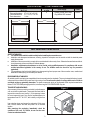
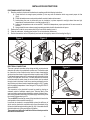
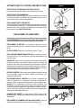
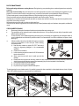
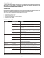
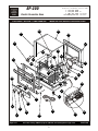
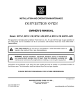
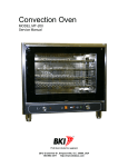
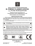
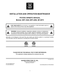
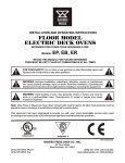
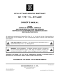
BAKERS
PRIDE
INSTALLATION AND OPERATING INSTRUCTIONS
Cyclone
SERIES
1/2-SIZE ELECTRIC CONVECTION OVEN
Model: BP-200
INTENDED FOR OTHER THAN HOUSEHOLD USE
RETAIN THIS MANUAL FOR FUTURE REFERENCE
OVEN MUST BE KEPT CLEAR OF COMBUSTIBLES AT ALL TIMES
!
FOR YOUR SAFETY: Do not store or use gasoline or other flammable vapors and
liquids in the vicinity of this or any other appliance.
!
!
WARNING: Improper installation, adjustment, alteration, service or maintenance
can cause property damage, injury or death. Read the Installation, Operating and
Maintenance Instructions thoroughly before installing or servicing this equipment.
!
!
WARNING: Initial heating of oven may generate smoke or fumes and must be
done in a well-ventilated area. Overexposure to smoke or fumes may cause
nausea or dizziness.
!
This equipment has been engineered to provide you with year round dependable service when used
according to the instructions in this manual and standard commercial kitchen practices.
ERTEK
INT
CM
VERIFIED
P/N U4162A 1-08
BAKERS PRIDE OVEN CO., INC.
30 Pine Street
New Rochelle, NY 10801
(914) 576-0200 Phone
(914) 576-0605 Fax
(800) 431-2745 US & Canada
www.bakerspride.com Web Address
1
INDEX
TECHNICAL DATA ................................................................................................................................................................ 2
Data plate ............................................. ......................................................................................................................... 2
Power supply terminal board .......................................................................................................................................... 2
After sales service .......................................................................................................................................................... 2
Specifications.................................................................................................................................................................. 3
PART RESERVED FOR INSTALLER......................................................................................................................................3
Safety standards .............................................................................................................................................................3
Environmental standards ................................................................................................................................................3
Transport and unpacking ................................................................................................................................................3
Installation instructions ................................................................................................................................................... 4
Electrical connections .....................................................................................................................................................4
Automatic safety and control devices of the oven .......................................................................................................... 5
Replacing spare parts .....................................................................................................................................................5
PART RESERVED FOR USER ...............................................................................................................................................6
General safety standards ................................................................................................................................................6
Use of the oven ...............................................................................................................................................................6
Routine maintenance ......................................................................................................................................................7
What to do in case of a breakdown or long periods of disuse ........................................................................................ 8
PARTS LIST & EXPLODED VIEW ......................................................................................................................................... 9
ELECTRICAL DIAGRAM ........................................................................................................................................................11
WARRANTY.............................................................................................................................................................................12
IMPORTANT FOR FUTURE REFERENCE
Please complete this information and retain this manual for the life of the equipment. For
Warranty Service and/or Parts, this information is required.
Model Number
Serial Number
Date Purchased
TECHNICAL DATA
DATA PLATE
The data plate containing the oven characteristics is glued to the back.
POWER SUPPLY TERMINAL BOARD
The power supply terminal block is inside the right side of the oven. A small data plate positioned near the terminal block
states the types of connections which are possible.
AFTER SALES SERVICE
Technical Service: Perfect operation over time of our convection ovens is ensured by a wide-ranging technical service
network. Specialized technicians are ready to intervene in a timely manner to ensure the work of food services professionals
continues uninterrupted.
Warranty: All our convection ovens undergo careful operating tests before they go on the market, as shown by the test
certificate that is enclosed with each one of them and by the one-year guarantee.
2
SPECIFICATIONS
Dimensions
WxDxL
External dimensions:
Internal dimensions:
Rack dimensions:
27”
½ Oven Technical Data
No. of pans
or racks
4
27” x 21 3/4” x 25 1/4”
21 ½” x 14 ½” x 16 1/8”
½ size
Power supply
1 Phase 15, Amp, 240V, 60Hz
Plug NEMA 6-20P standard
Power
Kw 3.2
21 3/4”
25 1/4”
For further electrical details, refer to the electrical diagram in this manual.
PART RESERVED FOR INSTALLER
SAFETY STANDARDS
The installer must read this booklet carefully before installing the convection oven.
Installation and subsequent maintenance, cleaning, inspection and repairs must be carried out with the electrical power
supply disconnected.
! Installation of the ovens must be in comply with current standards in the country of use. Otherwise the manufacturer shall not
honor the warranty in the event of direct or indirect damage.
! Installation, adjustment and assistance are to be carried out by qualified personnel in compliance with current
accident prevention legislation in the country of use. The installer must also check for any fire prevention
regulations.
! The manufacturer shall not be held liable for any damage arising from improper use of the convection oven, unauthorized
modifications and anything not covered by this manual.
!
!
ENVIRONMENTAL STANDARDS
All materials used for packaging are compatible with environmental protection standards. They may be stored without any hazard,
or disposed of in accordance with current laws in the country of use. Do not leave the plastic coverings within reach of children
or animals as they are potentially hazardous. The plastic components which can be disposed of and recycled are marked as
follows: POLYETHYLENE: packaging outer film, instructions bag, etc. POLYPROPYLENE: clips, etc.
TRANSPORT AND UNPACKING
Any movement of the oven must be carried out by suitable means
such as a forklift or pallet loader. These must be at least half as
large as the convection oven (see fig.1). If it is necessary to store
the oven temporarily, keep it in a covered, ventilated place at a
temperature from 14°F to 122°F, with humidity no higher than
95%.
Use protective gloves and remove the packaging. Lift the oven
with a forklift, remove the base and place it in its intended
location.
After removing the packaging, immediately check the
condition of the oven. If in doubt, do not use the oven.
Contact an authorized retailer.
3
Figure 1
INSTALLATION INSTRUCTIONS
POSITIONING AND SET-UP FOR USE
1) Place the machine in its place of intended use in compliance with the following instructions:
A) Check that there is enough space (minimum 8”) from any walls or obstacles which may prevent proper air flow
(fig.2).
B) Check that maintenance can be performed with a certain freedom of movement.
C) Avoid placing the oven in places with poor air circulation, in places exposed to sunlight, where there are high
temperatures, near heat sources or in windy locations (fig.3).
D) Ambient air temperature must not exceed 89°F. Above that temperature, proper operation of the oven cannot be
ensured.
E) Always install the oven under a properly operating aspiration hood for the extraction of vapors.
2) Remove the film which covers some parts of the oven before starting to use it.
3) Clean all substances, including glue residue. Do not use abrasive substances.
4) Position the machine so that it is perfectly level and set the height by means of the leveling feet (fig. 4).
Figure 2
8”
19
”
Figure 3
Figure 4
8””
19
8”
”
19
ELECTRICAL CONNECTIONS
The oven is setup for operation at the voltage set forth on the technical
data plate. All ovens are provided with a power cord. The flexible cable
for connection to the electrical mains must not have characteristics
which are less than those of a type with rubber insulation mod. H07RN
F and it must have a section which corresponds with that set forth in the
section “Technical Data” of the oven. The cable must also be anchored
to the frame with the cable clamp, the screw of which can be reached
through a hole in the frame. It must in any case be positioned in such a
way that at no point does it reach a temperature which is 122°F greater
than the ambient temperature. It must be type SJTO plug 20A 250V P
section 3xAWG12.
The connection to the electrical line must be made by placing an
automatic switch of sufficient capacity (see “Technical data” of the
oven) and with an opening distance between contacts of at least 3 mm.
Also, during operation of the oven, the power supply must not vary from
the nominal voltage value by ±10%.
The oven MUST be earthed by means of the terminal which carries the
earth symbol on the connection board (fig. 6).
It must also be inserted in an equipotential system (the efficiency of
which must be checked in accordance with current standards) using
the terminal with the equipotential symbol (fig. 6A). It is located near the
electrical cable entry on the panel of the oven bottom.
The manufacturer will not be held liable if this accident prevention
standard is not adhered to.
4
Figure 5
Figure 6
Figure 6A
AUTOMATIC SAFETY & CONTROL DEVICES OF OVEN
Figure 7
PROTECTION OF THE AUXILIARY ELECTRICAL CIRCUIT
It is checked by the fuses positioned on a terminal block at the line entry.
PROTECTION OF THE CHAMBER FAN
A remote switch stops the fan motor in the event of a malfunction or overload.
It is located behind the oven and must be reset manually. When it cuts in, it
stops the motor and shuts off the heating elements.
OVEN CHAMBER SAFETY THERMOSTAT
The safety thermostat disconnects the heating elements if the temperature in
the oven chamber is too high (644°F). It must be reset manually. If it activates,
technical service must be notified. All components are protected by the
following type of fuse: CLASS CC,G 600V 20A.
Figure 8
REPLACEMENT OF SPARE PARTS
Replacement of spare parts must be performed exclusively by qualified
and AUTHORIZED personnel. Turn the main switch OFF and unplug the
convection oven before carrying out any spare parts replacement.
REPLACEMENT OF MOTORS: It is necessary to remove the back by
removing the 4 fastening screws “A” and the 4 screws “B” that support them
(fig.8).
OUTER COVERING: Remove the 4 rear fastening screws “C” (fig.9).
2
11
2
A
A
B
B
BULB, HEATING ELEMENT AND MOTOR FAN: It is necessary to access
the inside of the oven, first removing pans, racks and related supports, and
then the conveyor.
30W MOTOR: Remove the fan by following the procedure outlined above,
disconnect the motor from the electrical system, loosen the 4 screws and
replace the motor. Before re-installing the fan, check that there is no friction
between the motor shaft and the ring nut located inside the oven. If there is,
loosen the fixing screws of the ring nut and re-tighten them after eliminating
the friction and having centered the ring nut on the motor shaft.
Figure 9
C
C
HEATING ELEMENTS: Disconnect the heating element connections outside
the oven chamber. Loosen the heating elements from inside the oven
chamber and replace them.
ELECTRO-MECHANICAL CONTROLS: All the electric components are
visible. To replace them it is necessary to disconnect the attachments,
remove the knobs, unscrew the fastening screws or nuts and replace them.
Attention: For theadjustable thermostat, safety thermostat and
thermometer, unscrew the guard and the supports and remove the bulbs.
Once they have been replaced use high-temperature resistant silicone to
seal the holes. After replacement, reseal the holes for the passage of the
capillaries with high temperature silicone.
CHAMBER FACE GASKET: It is simply pressed in. Pull to remove it. NB:
Before removing it, note its position carefully so as to place the new one in the
same position.
REPLACEMENT OF CHAMBER LIGHT AND GLASS GASKET: Check and
replace the glass gasket and any lights in the oven chamber (fig.10).
5
Figure 10
PART RESERVED FOR THE USER
GENERAL SAFETY STANDARDS
This manual is part of the documentation provided with the oven and contains all required
information for proper use and maintenance of the convection oven.
! Carefully read the user’s instructions contained in this manual before turning the oven
on. Special attention must be given to the standards concerning the automatic safety and
control devices.
! The user must carefully read the instructions in it and keep it where it is accessible to all
authorized users;
The ovens is of a professional type and must be used only by qualified personnel, which is the cooking of foods in food
service facilities.
Always turn off the main electrical switch after using the oven, especially during maintenance and repair or in the event of
long periods of disuse.
It is advisable to have the oven checked on a yearly basis by an authorized technical service center.
The owner of the oven must periodically train their staff on the use of the machines and provide them with safety instructions.
During cooking, the external parts of the oven (e.g. door glass) may get hot. Be careful when touching them.
!
!
!
!
!
!
GENERAL INSTRUCTIONS FOR USE
!
!
!
!
!
!
!
!
!
Figure 11
The oven may be used to bake creams, cookies, cakes, sauces and
pizza, for au gratin cooking and for defrosting frozen food convection ovens.
Avoid adding salt to foods in the cooking chamber.
Try to distribute foods evenly in the pans, avoiding accumulations.
Between one level and the next there must be a space of at least 1 ½”.
Hot air must be able to circulate both above and below the food in order for it.
Do not use pans with sides that are higher than necessary. The sides
Create a barrier to air circulation.
When using the oven for the first time, it is advisable to run it empty at maximum temperature for about an hour. This will
eliminate any unpleasant odors from protective lubricants used in the factory.
Leave room between dishes on the same level.
Preheat the oven. It is always better to place the food in a pre-heated oven.
During cooking, racks and pans reach very high temperatures. Use caution to prevent burns.
USE OF THE OVEN
2
3
1
KEY TO CONTROL PANEL SYMBOLS
1)
2)
3)
TIME SETTING KNOB: Sets cooking time from 0 - 120 minutes or to continuous operation.
TEMPERATURE SETTING KNOB: Sets chamber temperature from 50 to 520°F
ON/OFF MAIN SWITCH
START-UP AND USE
To start the oven, press the main switch (3) ON/OFF. Set the cooking time by turning the time setting knob (1) . Then use knob (2) to
set the desired cooking temperature. If knob (2) is left in position ‘0’, only the light and fan will operate, and the oven chamber will not
heat up.
SWITCHING OFF
Cooking ends automatically when the cooking time set on knob (1) has expired. Nonetheless, turn all knobs to “O” and turn off the
main switch (3) ON/OFF.
6
ROUTINE MAINTENANCE
Before performing maintenance, unplug the oven. During cleaning, use protective gloves, mask and garments as required by
standards.
At the end of each workday clean the inside of the oven with appropriate convection ovens following the suggestions of your
supplier. Do not use corrosive or acidic convection ovens, or convection ovens which are not suitable for this type of cleaning.
To make cleaning easier, remove the lateral diffusers by lifting them slightly so they are free of the holding pegs.
Clean the stainless steel parts daily with lukewarm soapy water, and rinse thoroughly. Then dry.
Absolutely do not clean the stainless steel with steel wool or common steel brushes, since they may leave ferrous particles which
may oxidize, thus causing rust spots.
Stainless steel wool can be used in the direction of the satin finish.
If the oven is not used for long periods, use a cotton ball to lay a coat of petroleum jelly on all surfaces; also regularly ventilate the
rooms.
OVEN CHAMBER CLEANING
Remove any food and/or fat residues from the oven chamber after each cooking cycle.
The combination of fat, heat and forced circulation dirties the oven. Only by cleaning the oven daily is it possible to avoid
difficult cleaning operations.
!
To clean the oven, use a suitable de-greasing convection oven (non-foaming) as suggested by your detergent retailer. A
spray is preferable to reach behind the protection shield. Do not use abrasive or corrosive substances, scrapers or steel
wool (fig.12).
Figure 12
!
Adhere to safety instructions included with cleaning convection
ovens for the protection of skin and eyes. When cleaning,
proceed as follows:
a) Heat the oven chamber to approx.158-176°F and clean it
using the de-greasing detergent in the recommended
quantities.
b) Close the oven and heat it.
c) Let the cleansing convection oven act for 20-30 minutes and
then turn the oven off.
d) Slowly open the oven with care to avoid eye and skin
damage.
e) Remove the racks or pans from the oven, remove the rack supports attached to the side and shield, remove the
shield by loosening the fastening screws. Wash separately (they can also be placed in the dishwasher).
f) Clean and rinse the oven and fan with water.
g) Re-install the shield and the rack supports.
h) Dry the oven by turning the CONVECTION cycle on.
!
!
To make cleaning the oven chamber easier, it is possible to remove the door completely in a few simple steps as shown in figures
13A & 13B. Follow the sequence in reverse order to re-install the door.
Figure 13A
Figure 14
Figure 13B
A
A
2
1
7
CLEANING DOOR GLASS
To reach the inside glass of the oven door, use the lower latch “A”, open outer glass “B” raising it from the bottom upwards. This will
make it possible to get inside the glass for normal cleaning. Upon completion, close the external glass by pushing it slowly
downwards until the click is heard of insertion in component “A”.
CLEANING THE FAN
Periodically check the condition of the fan. Make sure that there is not too much grease on the blades since it may slow motor
rotation (which in turn may lead to overheating) and uneven heat distribution (resulting in uneven cooking).
WHAT TO DO IN CASE OF A BREAKDOWN OR LONG PERIODS OF INACTIVITY
!
!
!
!
Switch off the main electrical switch.
Set all control panel knobs to zero.
Inform technical assistance (only in case of a malfunction).
Clean the oven inside and out.
TROUBLESHOOTING GUIDE
PROBLEM
PROBABLE CAUSE
REMEDY
Oven does not turn on
Unit unplugged
Check the plug connection and reconnect if necessary
Fuses
Check the fuses and replace them if necessary
Cables/terminal block
*Check the cables connection for loose wire and reconnect if
necessary
Switch
*Check the switch and the voltage at the inlet and outlet. Replace
switch if necessary
Safety thermostat
Check the safety thermostat and push the red button
Resistor contactor
*Check the voltage at the inlet and outlet of the contactor and replace
if necessary
Heating element burn out
*Replace the heating element
Thermostat
*Check the temperature with a manual thermometer and if
necessary replace the thermostat
Lights not lit
Switch/lights
*Check the switch and the lights and replace if necessary
Motors do not work
Motor contactor/Motor
*Check the voltage at the inlet and outlet of the contactor. Check the
motor and replace the contactor or the motor if necessary
Oven suddenly stops
Safety thermostat
Oven does not warm up
Short circuit
Push the red button on the thermostat
*Check the fuses and replace them if necessary, if the failure persists
check all parts with an appropriate tester in order to find which is the
part to replace
*NOTE: CALL BAKERS PRIDE FACTORY AUTHORIZED SERVICE CENTER
8
BP-200
BAKERS
PRIDE
30 Pine Street • New Rochelle • New York • 10801
1 - 914 / 576 - 0200
1 - 914 / 576 - 0605 fax
1 - 800 - 431 - 2745 US & Canada
www.bakerspride.com web address
Electric Convection Oven
EXPLODED / ÉCLATÉ / COMPONENTES
Model: BP-200 Electric Convection Oven
94AT
92AS
94AU
69AA
95
96U
10*
144Q
6AH
50D
33E
72*
1F*
146AG
71A
2AA*
136
51C
143Q
88H
129A
11Q
27G
146AG
11P
45I
47C
13
40G
40G
35D
153E
38A
37A
Page 1 of 2
79G
44
93AH
Note: When ordering, ALWAYS specify Part #, Model #, Serial #, Voltage/Phase & type of Gas.
9
U4167A 6/07
BP-200
BAKERS
PRIDE
30 Pine Street • New Rochelle • New York • 10801
1 - 914 / 576 - 0200
1 - 914 / 576 - 0605 fax
1 - 800 - 431 - 2745 US & Canada
www.bakerspride.com web address
Electric Convection Oven
PARTS LIST
Model: BP-200 Electric Convection Oven
POS.
CODE
DESCRIPTION (ENGLISH)
DESCRIPTION (FRENCH)
DESCRIPTIÓN (SPANISH)
1FI
0014
MONPHASE MOTOR
MOTEUR MONOPHASE
MOTOR MONOFÁSICO
2M I
0163
HEATING ELEMENT
RESISTANCE
RESISTENCIA
l1P
0596
THERMOSTAT
THERMOSTAT
TERMOSTATO
13
0050
TIMER
MINUTEUR
TEMPORIZADOR
l1Q
0166
THERMOSTAT
THERMOSTAT
TERMOSTATO
27G
10024
CONTACTOR
CONTACTEUR
CONTAGOR
38A
0616
GREEN LAMP
TEMOIN VERT
INDICADOR VERDE
37A
0617
RED LAMP
TEMOIN ROUGE
INDICADOR ROJO
33E
14075
GASKET
JOINT
JUNTA
79G
10338
FUSE
FUSIBLE
FUSIBLE
451
10339
FUSE-HOLDER TERMINAL
PORTE-FUSIBLES
PORTAFUSIBLES
44
0012
TERMINAL BOARD
BORNIER
BORN ERA
7Z1
1523.01
DOOR GLASS
VITRE PORTE
PUERTA CRISTAL
50D
10342
LAMP HOLDER
DOUILLE POUR AMPOULE
PORTA-BOMBILLA
101
35.0003.01
LAMP 15W
AMPOULE 15W
BOMBILLA 15W
6AH I
10304
GLASS SEAL
JOINT VITRE
JUNTA DE CRISTAL
71A
10305
GLASS FOR LAMP HOLDER
VERRE AMPOULE
VETTRO PORTALAMPADA
136
10306
OVEN LIGHT FIXING FRAME
ENCAD. LAMPE PORTE
ELEM. FIJACIÓN BOMBILLA
40G
15021
KNOB
MANETTE
MAN DO
35D
10353
SWITCH
INTERRUPTEUR
INTERRUPTOR
153E
10586
POWER CORD 3X12
CORDON D'ALIMENTATION
CABLE DE AUMENTACIÓN
51C
471
CABLE LOCK
SERRE-CABLE
SUJETA CABLES
47C
0364A
FOOT
PIED
PATAS
93AH
35365
ASSEMBLY DOOR KIT
KIT ENS. PORTE
CONJUNTO PUERTA HORNO
^
95
10951
WIRING
CABLAGE
CABLEADO
129A
20045
TRAY
BAC
CUBETA
146AG
0020
OVEN RUNG SUPP.
SUPPORT GRILLE
PORTABANDEJAS
143Q
16754AFO
CONTROL PANEL
BAN DEAU
PANEL DE CONTROL
96U
35350
BACK
PANNEAU POSTERIEUR
TRASERA
24
15062
OVEN DOOR HINGE
39P
35370
HANDLE
CHARNIÈRE PORTE DU FOUR BISAGRA PUERTA HORNO
TIRADOR
POIGNEE
69M
35379
PIPE
PIPE
TUBO
144Q
35355
CONVEYOR
CONVEGEUR
CONVEGOR
88H
12167
PIN
CHEVILLE
PERNO
92AS
35360
COVER
COUVERCLE
COBERTURA
94AT
35373
RH SIDE
COTE DROIT
LADO DERECHO
94AU
35374
LH SIDE
COTE GAUCH E
LADO IZQUIERDO
Page 2 of 2
Note: When ordering, ALWAYS specify Part #, Model #, Serial #, Voltage/Phase & type of Gas.
10
U4167A 6/07
ELECTICAL DIAGRAM / SCHÉMA ÉLECTRIQUE / ESQUEMA ELÉCTRICO
GROUND
F1
F2
1
3
5
4
6
KR
P2
2
1
3 5
KM
2
4
6
ON/OFF
R1
R2
M1
1
S2
2
M2
P1
LS2
A1 LCA
KM
A2
Notes:
11
LP1
A1
KR
A2
BAKERS PRIDE LIMITED WARRANTY
30 Pine Street New Rochelle, New York 10801
914 / 576 - 0200 ♦ US & Canada: 1 - 800 - 431 - 2745 ♦ fax 914 / 576 - 0605
WHAT IS COVERED
This warranty covers defects in material and workmanship under normal use, and applies only to the original purchaser
providing that:
♦ The equipment has not been accidentally or intentionally damaged, altered or misused;
♦ The equipment is properly installed, adjusted, operated and maintained in accordance with National and local codes. and
in accordance with the installation instruction provided with the product;
♦ The serial number rating plate affixed to the equipment has not been defaced or removed.
WHO IS COVERED
This warranty is extended to the original purchaser and applies only to equipment purchased for use in the U.S.A.
COVERAGE PERIOD
Full size gas and electric deck ovens: Two (2) year limited parts and labor: Cyclone Convection Ovens: BCO Models: One (1)
Year limited parts and labor; BP-200 Models: One (1) Year limited parts and labor; GDCO Models: Two (2) Year limited parts
and labor; CO II Models: Two (2) Year limited parts and labor; (5) Year limited door warranty.
All Other Products: One (1) Year limited parts and labor.
Warranty period begins the date of dealer invoice to customer or ninety (90) days after shipment date from BAKERS PRIDE whichever comes first.
WARRANTY
COVERAGE
This warranty covers on-site labor, parts and reasonable travel time and travel expenses of the authorized service
representative up to (100) miles. round trip, and (2) hours travel time. The purchaser. however, shall be responsible for all
expenses related to travel, including time. mileage and shipping expenses on smaller counter models that may be carried into
a Factory Authorized Service Center, including the following models: PX-14. PX-16, PI8, and BK-I8.
EXCEPTIONS
All removable parts in BAKERS PRIDE Char-broilers, including but not limited to: Burners, Grates. Radiants, Stones and
Valves, are covered for a period of SIX MONTHS.
All Ceramic Baking Decks are covered for a period of THREE MONTHS. The installation of these replacement decks is the
responsibility of the purchaser.
The extended Cyclone door warranty years 3 through 5 is a parts only warranty and does not include labor, travel, milage or
any other charges.
EXCLUSIONS
♦ Failures caused by erratic voltages or gas supplies,
♦ Unauthorized repair by anyone other than a BAKERS PRIDE
Factory Authorized Service Center,
♦ Damage in shipment,
♦ Alteration, misuse or improper installation,
♦ Thermostats and safety valves with broken capillary tubes.
♦ Accessories - spatulas, forks. steak turners, grate lifters,
oven brushes, scrapers, peels. etc.,
♦ Freight - other than normal UPS charges,
♦ Ordinary wear and tear.
♦ Negligence or acts of God,
♦ Thermostat calibrations after (30) days from equipment
installation date,
♦ Air and Gas adjustments,
♦ Light bulbs,
♦ Glass doors and door adjustments.
♦ Fuses,
♦ Char-broiler work decks and cutting boards,
♦ Tightening of conveyor chains,
♦ Adjustments to burner flames and cleaning of pilot burners,
♦ Tightening of screws or fasteners.
INSTALLATION
Leveling and installation of decks. as well as proper installation and check out of all new equipment - per appropriate
installation and use materials - is the responsibility of the dealer or installer, not the manufacturer.
REPLACEMENT
PARTS
BAKERS PRIDE genuine Factory OEM parts receive a (90) day materials warranty effective from the date of installation by a
BAKERS PRIDE Factory Authorized Service Center.
This Warranty is in lieu of all other warranties, expressed or implied, and all other obligations or liabilities on the manufacturers part. BAKERS PRIDE
shall in no event be liable for any special, indirect or consequential damages, or in any event for damages in excess of the purchase price of the unit. The
repair or replacement of proven defective parts shall constitute a fulfillment of all obligations under the terms of this warranty.
Form #U4177A 1/07
12