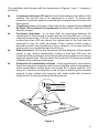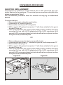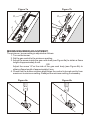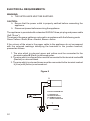
1
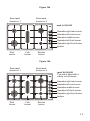
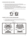
LGHS 90II
DGHS 90II
COOKTOPS
INSTALLATION and SERVICE INSTRUCTIONS
USE and CARE INSTRUCTIONS
distributed by
DèLonghi
Pty Ltd
Use and Care
INSTALLATION
CAUTION:
< This appliance must be installed in accordance with these installation
instructions, local gas fitting regulations, municipal building codes, water
supply regulations, electrical wiring regulations, AS5601 / AG 601 - Gas
Installations and ony other relevant statutory regulations.
< This appliance shall only be serviced by authorized personnel.
WARNING:
< This appliance is to be installed only by an authorised person.
< This appliance must be used only for the task it has explicity been designed for,
that is for cooking foodstuffs. Any other form of usage is to be considered as
inappropriate and therefore dangerous.
< Do NOT place combustible materials or products on this appliance at any time.
< Do NOT spray aerosols in the vicinity of this appliance while it is in use.
This hob has been designed and constructed in accordance with the following
codes and specifications:
AGA101
AS/NZS 3350-1
AS/NZS 3350-2-6
AS/NZS 1044
Approval requirements for Domestic Gas cooking appliances
General requirements for Domestic electrical appliances
Particular requirements for Domestic electrical cooking appliances
Electromagnetic Compatibility requirements
IMPORTANT NOTE: THIS APPLIANCE SHALL NOT BE USED AS A SPACE
HEATER, ESPECIALLY IF INSTALLED IN MARINE CRAFT OR CARAVANS.
NOMINAL GAS CONSUMPTION AND INJECTOR SIZES (Table 1):
Natural Gas
LPG
1.0
2.75
Test Point
Pressure (kPa)
Injector Orifice
[mm]
Gas Consumption
[MJ/h]
Injector Orifice
[mm]
Gas Consumption
[MJ/h]
Simmer
0.70
2.4
0.47
2.9
Semi-rapid no.1
0.90
4.0
0.60
4.7
Semi-rapid no.2
1.15
6.5
0.76
7.5
Wok burner
1.45
11.0
0.90
10.4
Fish burner
1.45
11.0
0.90
10.4
Burner
(Note: Gas type sticker and data are attached to the underside of the base of the
appliance.)
2
Figure 1
DIMENSIONS (Table 2):
(Note: Also refer to Figure 1)
General Dimensions
Width
860 mm
Depth
500 mm
Depth Below Mounting Surface
30 mm
Cut-out Dimensions
Width
840 mm
Depth
480 mm
3
Use and Care
INSTALLATION
Installation clearances and protection of combustible surfaces shall comply with
CLEARANCES:
the requirements of AS5601 / AG 601 - Gas Installations.
4
750 mm
450 mm
Figure 2
The installation shall comply with the dimensions in Figures 1 and 2 bearing in
mind that:
<
<
<
<
A minimum distance of 20 mm has to be kept between the bottom of the
cooking hob and the top of an appliance or a shelf. To ensure this
clearance, mount the spacers, supplied with the appliance as shown in the
figure below.
A partition between the base of the hob and the cupboard below should
be fitted 100 mm below the workbench surface if the cupboard is to be
used for storage.
Overhead clearances - In no case shall the clearances between the
highest part of the hob and a range hood be less than 600 mm, or for an
overhead exhaust fan, 750 mm. Any other downward facing combustible
surface less than 600 mm above the highest part of the hob shall be
protected for the full width and depth of the cooking surface area in
accordance with local regulations in force. However, in no case shall this
clearances to any surface be less than 450 mm.
Side clearances - Where the dimension from the periphery of the nearest
burner to any vertical combustible surface is less than 200 mm, the
surface shall be protected in accordance with local regulations in force to a
height of not less than 150 mm above the hob for the full dimension (width
or depth) of the cooking surface area.
Protection of combustible surfaces - Local regulations in force specify
that where required, protection shall ensure that the surface temperature
of the combustible surface does not exceed 50°C above ambient. The
fixing of 5 mm thick ceramic tiles to the surface or attaching fire resistant
material to the surface and covering with sheet metal with minimum
thickness of 0.4 mm would satisfy this requirement.
20 mm
<
Spacer
Double sided
adhesive tape
Figure 3
5
INSTALLATION (Refer to Figures 4a and 4b):
< Spread out the gasket “C” over the workbench of the edge of the cut out
taking care to overlap the gasket of the corners.
< Slot in the cooking hob into the cut out of the workbench and locate it
correctly.
< Adjust the clamps “A” and tighten the screws “B” until the hob is firmly
secured.
< Using a sharp tool, trim any excess gasket which protrudes from the edge
of the hob.
< Assemble the three piece burners. Take care to properly locate the
assembled burner on the burner base.
Figure 4a
B
A
Figure 4b
6
40 mm max.
40 mm max.
A
20 mm min.
B
20 mm min.
C
C
GAS SUPPLY:
< This appliance is suitable for use with Natural Gas or LPG. (Check the “gas
type” sticker attached to the appliance).
< For Natural Gas the gas supply must be regulated to obtain a pressure of 1
kPa with the two semi-rapid burners operating at maximum.
< For LPG models connect the gas supply directly to the appliance test point
adaptor (supplied with the conversion kit) and ensure that the supply
pressure is regulated to 2.75 kPa.
< Do NOT force the “elbow” rotation prior to loosening the nut.
< Do NOT over tighten the nut at the “elbow”.
1. After connecting the gas supply, check the piping and connections for leaks
using a soap and water solution. The presence of bubbles indicates a leak,
tighten or replace connections as appropriate.
2. Adjust the test point pressure or supply pressure to the value which is
appropriate for the gas type.
3. Turn on the appliance gas controls and light each burner. Check for a well
defined blue flame without any yellow tipping. If any abnormality is evident then
check that the burner cap is located properly and the injector nipple is aligned
correctly.
4. Check the minimum burner setting by quickly rotating the gas control knob from
the maximum to the minimum position, the flame must not go out. If adjustment
is required, carry out the “minimum burner setting adjustment” procedure
described below.
5. If satisfactory performance cannot be obtained, the installer shall check the
installation and notify the local gas supply authority for a gas supply problem, or
if it is an appliance problem, our Customer Service Centre should be called to
obtain the nearest authorised Service Agent.
6. Where the appliance data plate cannot be easily read with the appliance in the
installed position the duplicate data plate must be attached to adjacent surfaces
and the duplicate ULPG conversion label should also be included where a
ULPG conversion has been completed.
Gas connection for Natural Gas
Gas inlet pipe
Figure 5
Gas connection for LPG
Gas inlet pipe
Gasket
Gasket
Brass conical adaptor
(Thread tight: use suitable seal)
Brass conical adaptor
(Thread tight: use suitable seal)
Gas regulator
Test point adaptor
7
CONVERSION PROCEDURE
INJECTOR REPLACEMENT:
This appliance is suitable for use with Natural Gas or LPG. (Check the gas type”
sticker attached to the appliance.) The nominal gas consumption and injector size
details are provided in Table 1.
The conversione procedure must be carried out only by an authorised
person.
To replace injectors:
1. Remove the knobs and ignition push button.
2. Unscrew the “A” screw in Figure 6a.
3. Remove the control panel “B” in Figure 6a.
4. With a wrench “C” replace the injectors “J” with those suitable for the gas to
be used (Figure 7a).
5. Affix to the appliance the warning label stating that the cooktop has been
converted for use with ULPG (supplied with the ULPG conversion kit).A
second ULPG conversion label should also be affixed to an adjacent surface
along with the duplicate data plate.
OR
1. Remove the pan-supports, the burners and the knobs.
2. Unscrew the 8 side screws “C” indicated in figure 6b, and the top screws “D”.
3. Remove the 4 rear plugs “T”.
4. With a wrench “C” replace the injectors “J” with those suitable for the gas to
be used (Figure 7b).
5. Affix to the appliance the warning label stating that the cooktop has been
converted for use with ULPG (supplied with the ULPG conversion kit).A
second ULPG conversion label should also be affixed to an adjacent surface
along with the duplicate data plate.
Figure 6a
Figure 6b
D
T
T
C
8
Figure 7a
Figure 7b
C
C
J
J
J
J
MINIMUM BURNER ADJUSTMENT:
The minimum burner setting is adjusted as follows:
1. Turn on the burner.
2. Set the gas control to the minimum position.
3. Adjust the screw inside the gas cock shaft (see Figure 8a) to obtain a flame
length of approximately 4 mm.
OR
Adjust the screw “A”on the side of the gas cock body (see Figure 8b) to
obtain a flame length of approximately 4 mm.
4. Check that the burner remains alight when the control is turned quickly from
maximum to minimum setting. Readjust the minimum setting if necessary.
Figure 8a
Figure 8b
A
9
ELECTRICAL REQUIREMENTS:
WARNING:
4 THIS APPLIANCE MUST BE EARTHED.
CAUTION:
4 Ensure that the power outlet is properly earthed before connecting the
appliance.
4 Disconnect power before servicing the appliance
The appliance is provided with a standard 240VAC three pin plug and power cable
(3x0.75 mm2).
The wires in the power cable are coloured in accordance with the following code:
Green/Yellow = Earth, Blue = Neutral, Brown =Active
If the colours of the wires in the power cable to the appliance do not correspond
with the coloured markings identifying the terminals in the junction terminal,
proceed as follows:
1. The wire which is coloured green and yellow must be connected to the
terminal marked E (Earth) or coloured green.
2. The wire which is coloured blue must be connected to the terminal marked N
(Neutral) or coloured black.
3. The wire which is coloured brown must be connected to the terminal marked
L (Live) or A (Active) or coloured red.
Figure 9
A
ELECTRIC DIAGRAM KEY
A IGNITION COIL
PA IGNITION SWITCH
M TERMINAL BLOCK
T EARTH CONNECTION
PA
T
M
113930
10
Note: Servicing of this appliance is only to be carried out by
Authorised Persons.
REPLACEMENT OF IGNITION MODULE/ELECTRODES/GAS
COCKS:
1. Turn off and disconnect gas supply and electricity.
2. Lift off trivets and burner heads, and pull off ignition push button and control
knobs.
3. Undo the screws “B” and remove the clamps “A” shown in Figures 4a/4b and
remove the hob.
4. Remove screws securing the top of the hob to the base pan and lift it off.
5. To replace the electrode, unhook the locking spring and remove the
electrode and cable.
6. To remove the igniter module, disconnect the electrodes, power and igniter
switch wires, undo the two retaining screws and remove the module.
7. To remove the gas cock undo the two screws which secure it to the gas
manifold. On re-assembly ensure that the injectors are aligned with the
burner venturi.
8. Reassemble in reverse order.
9. Check all connections for gas leaks with soapy water (including gas cocks if
they have been removed).
GAS COCK LUBRICATION:
1. Turn off the gas supply and disconnect electricity.
2. Remove the knobs and ignition push button.
3. Unscrew the “A” screw and remove the control panel “B” (Figure 6a).
OR
Remove the hob top by following points 1-3 in REPLACEMENT OF
IGNITION MODULE/ELECTRODE/GAS COCKS section above.
4. Unscrew the two screws on top of the gas cock.
5. Lift out the valve cone, clean it with solvent and re-grease it with high
temperature grease.
6. Replace the valve cone, move it around and remove excess grease.
Remove it once again and check that internal holes or galleries are not
blocked.
7. Replace and reassemble in reverse order.
8. Check for gas leaks with soapy water.
11
Use and Care
USE and CARE
CAUTION:
4 This appliance must be used only for the task it has explicitly been
4
4
4
4
12
designed for, that is for cooking foodstuffs. Any other form of usage is to be
considered as inappropriate and therefore dangerous. Do not use this
appliance as a space heater.
Do NOT place combustible materials or products on this appliance at any
time.
Do NOT spray aerosols in the vicinity of this appliance while it is in use.
Before using for the first time, clean the cooktop with warm soapy water.
Use the coffee pot support to ensure that small cooking utensils are stable.
Figure 10a
Semi rapid
burner no. 1
Semi rapid
burner no. 2
mod. LGHS 90II
Operates right rear burner
Operates left rear burner
Operates middle burner
Operates left front burner
Operates right front burner
Ignition
Wok
burner
Fish
burner
Simmer
burner
Figure 10b
Semi rapid
burner no. 1
Semi rapid
burner no. 2
mod. DGHS 90II
The hob is fitted with a
safety cut-off device
Operates right rear burner
Operates left rear burner
Operates middle burner
Operates left front burner
Operates right front burner
Ignition
Wok
burner
Fish
burner
Simmer
burner
13
LIGHTING GAS BURNERS
4 Check that the electricity is switched on to allow spark ignition.
4 Make sure that all controls are turned to zero.
4 Model LGHS 90II: the gas flow to the burner is controlled by the knobs on
the safety taps.
4 Model DGHS 90II: the gas flow to the burner is controlled by the knobs on
4
the taps incorporating a safety cut-off device. If the burner flame should go
out, the safety cutoff valve will automatically stop the gas flow.
You control the flow by turning the knob indicator to line up with the
following symbols:
Symbol
: Off
Symbol
: Full on (maximum)
Symbol
: Minimum rate
4 Model LGHS 90 II: to ignite automatically, push the required knob down
4
4
4
4
14
and turn it to maximum then press the ignition button continuously until the
burner lights. When the flame is lit, you can control the temperature by the
knob.
Model DGHS 90 II: to ignite automatically, push the required knob down
and turn it to maximum, keeping the knob down, press the ignition button
continuously until the burner lights. When the flame is lit, wait for about ten
second with the knob down (safety cutoff device delay).
You can control the temperature by the knob to “maximum” from “minimum
rate”.
To switch off, turn the knob clockwise until you hear the safety click.
Note that, if you are using a burner at the minimum setting, you turn the
knob clockwise past the maximum setting before reaching the off position.
COOKING HINTS FOR GAS HOBS
4 The burners are different sizes, and can be used in different ways.
4 The largest can be used for boiling, to seal meat or foods that are cooked
quickly, and the smallest for stews and sauces.
4 Always ensure that you use the correct size of saucepan.
4 For fast boiling, make sure the flame just reaches the edge of the pan.
4
Flames going up the side of the pan means wasted heat and the contents
of the pan will take longer to boil.
For optimum efficiency use a wok or pan no smaller than 230mm diameter.
Figure 11
CORRECT USE OF DOUBLE-RING BURNER
4 The flat-bottomed pans are to be placed directly onto the pan-support.
4 To use the WOK you need to place the proper stand in order to avoid any
faulty operation of the wok burner.
Figure 12
WRONG
CORRECT
15
CLEANING AND MAINTENANCE
GENERAL ADVICE
4 It is advisable to clean when the appliance is cold and especially when
cleaning the enamelled parts.
4 Avoid leaving alkaline or acid substances (lemon juice, vinegar, etc.) on
the surfaces.
4 Avoid using cleaning products with a chlorine or acid base.
ENAMELLED PARTS
4 All of the enamelled parts must be washed only with a sponge and soapy
water or with non-abrasive products. Dry, preferably, with deer skin.
STAINLESS STEEL
4 Clean with a suitable product. Always dry fully with a soft cloth or chamois.
BURNERS AND RACKS
4 These parts may be removed and washed with suitable products.
4 Black burners (”OXI-BLACK” coating): They can be removed and
washed only with soapy water. Detergents can be used but must not be
abrasive or corrosive. Do not use abrasive sponges or pads. Do not put in
dishwasher.
4 The burners and their caps must be well dried after cleaning and put back
perfectly into their slots. It is very important to make certain the positioning
of the burner-caps because a misplacing in their slots can cause serious
damage.
4 In the appliances with electrical ignition for the burners, verify that the
electrode is always cleaned well to ensure a regular spark.
SERVICE AND MAINTENANCE
If the ignition spark fails to ignite or does not light the gas, check the following items
before calling our Customer Service Centre to obtain the nearest Authorised
Service Agent:
4 Burner is reassembled and located correctly.
4 Spark electrode and white ceramic are clean and dry.
4 240 VAC power supply is connected.
Contact the local gas utility or our Customer Service Centre to obtain the nearest
Authorized Service Agent.
4 You can smell gas when all burners are turned on.
4 The burners do not remain alight at the minimum marked setting.
4 The burner flame is yellow or emits an unusual odour.
Note that a bi-annual inspection of the appliance by an authorized service agent or
your locate gas utility will ensure many years of trouble free operation of your
appliance.
16
17
18
19
Code 1101579 - Ed.4 - b6
Descriptions and illustrations in this booklet are given as simply indicative.
The manufacturer reserves the right, considering the characteristics of the
models described here, at any time and without notice, to make eventual
necessary modifications for their construction or for commercial needs.