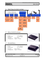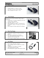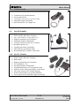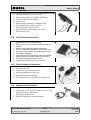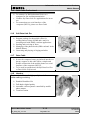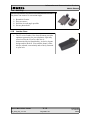
1
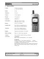
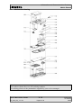
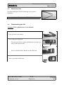
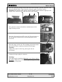
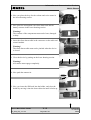
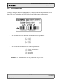
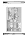
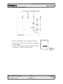
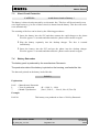
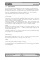
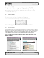
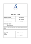
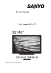
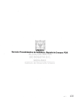
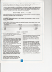
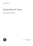
Information and Communication Products Mobile Phones Service Manual for S25 / S2588 V 1.1 Service Manual S25 / S2588 Sm_S25_lvl2_v11.doc V 1.1 Page 1 of 35 ICP CD ST R. Fleuren 02/00 Information and Communication Products Mobile Phones 1 Introduction The S25 is the first dualband handset (GSM-900 and GSM-1800) in the S-class. The S2588 is a special version for the asian market . It carries a different software which supports presentation of chinese character set in the phones display. This manual is intended to help you carry out repairs up to level 2 on the mobile telephones -S25 and S2588. For information on level 2.5 repairs or on the testequipment, please refer to the available documentation. The repairs for S25 and S2588 are identical unless otherwise noted, and therefore in the text only S25 is mentioned. Attention: It must be noted that all repairs have to be carried out in an environment set up according to the ESD (Electrostatic Discharge Sensitive Devices) regulations defined in international standards. If you have any questions or comments regarding repair procedures or this service manual, please do not hesitate to contact the technical support team in Kamp-Lintfort, Germany: : Ð: : Service Manual S25 / S2588 Sm_S25_lvl2_v11.doc +49 2842 95 4666 +49 2842 95 4302 [email protected] V 1.1 Page 2 of 35 ICP CD ST R. Fleuren 02/00 Information and Communication Products Mobile Phones 2 Table of Contents 1INTRODUCTION.................................................................................................................................................2 2TABLE OF CONTENTS......................................................................................................................................3 2 TECHNICAL DATA...........................................................................................................................................5 3 GENERAL INFORMATION.............................................................................................................................6 4 MECHANICAL CONCEPT...............................................................................................................................6 4.1 MECHANICAL DRAWING............................................................................................................................................8 4.2NECESSARY TOOLS....................................................................................................................................................9 4.3 DISASSEMBLING THE S25.........................................................................................................................................9 4.4 ASSEMBLING THE S25............................................................................................................................................13 4.5 HANDSET DATECODES............................................................................................................................................17 5 HARDWARE CONCEPT .................................................................................................................................................................................18 5.1 BLOCK DIAGRAM..................................................................................................................................................18 5.2 HARDWARE DESCRIPTION........................................................................................................................................19 5.3 POWER SUPPLY CONCEPT.......................................................................................................................................21 5.4 OVERVOLTAGE CONDITIONS ...................................................................................................................................21 6 SOFTWARE PROGRAMMING......................................................................................................................22 6.1HARDWARE OVERVIEW FOR SOFTWARE UPDATE..........................................................................................................23 6.2DESCRIPTION OF SOFTWARE BOOTING .................................................................................................................................................................................23 6.2 LANGUAGE GROUPS...............................................................................................................................................24 6.3CUSTOMER SPECIFIC INITIALISATIONS .................................................................................................................................................................................24 7 BATTERY...........................................................................................................................................................25 7.1SPECIFICATION........................................................................................................................................................25 7.2CHARGING.............................................................................................................................................................25 7.3 SCHEMATIC OF THE BATTERY...................................................................................................................................26 7.3SHORT CIRCUIT PROTECTION....................................................................................................................................27 7.4BATTERY DATECODES.............................................................................................................................................27 7.5DEEP DISCHARGE...................................................................................................................................................28 8 UNBLOCKING .................................................................................................................................................29 8.1 SIEMENS HOTLINE.................................................................................................................................................29 8.2 INTERNET SOLUTION...............................................................................................................................................29 9ACCESSORIES...................................................................................................................................................30 9.1RAPID CHARGER (INCLUDED IN PACKAGE)..................................................................................................................30 9.2BATTERY (INCLUDED IN PACKAGE)............................................................................................................................30 9.3EXTENDED BATTERY...............................................................................................................................................30 9.4RAPID CHARGER ....................................................................................................................................................31 9.5TRAVEL CHARGER..................................................................................................................................................31 9.6DESK TOP CHARGER...............................................................................................................................................31 9.7CAR CHARGER.......................................................................................................................................................31 9.8ANTENNA CRADLE...................................................................................................................................................32 9.9CAR KIT PORTABLE................................................................................................................................................32 9.10CAR KIT COMFORT..............................................................................................................................................32 9.11CAR HANDSET.....................................................................................................................................................33 Service Manual S25 / S2588 Sm_S25_lvl2_v11.doc V 1.0 Page 3 of 35 ICP CD ST R. Fleuren 06/99 Information and Communication Products Mobile Phones 9.12CAR KIT PROFESSIONAL VOICE..............................................................................................................................33 9.13PHONE ADAPTER PROFESSIONAL.............................................................................................................................33 9.14ADAPTER KIT PROFESSIONAL.................................................................................................................................33 9.15DATA CABLE PROFESSIONAL..................................................................................................................................34 9.16SOFT DATA LINK PRO..........................................................................................................................................34 9.17DATA CABLE.......................................................................................................................................................34 9.18HEADSET.............................................................................................................................................................34 9.19BELT CLIP...........................................................................................................................................................35 9.20LEATHER CASE....................................................................................................................................................35 Service Manual S25 / S2588 Sm_S25_lvl2_v11.doc V 1.0 Page 4 of 35 ICP CD ST R. Fleuren 06/99 Information and Communication Products Mobile Phones 2 Technical Data Length: 117 mm (w/o antenna) 137 mm (with antenna) Width: 47 mm Thickness: 23,5 mm Volume: 110 cm³ (approx.) Weight: 125 g (approx.) Standards: GSM Phase 2 Performance: GSM 900, Class 4 (2 Watt) GSM 1800, Class 1 (1 Watt) Battery: Li-Ion, 3.6V, 650mAh Standby time: Up to 200 hours (Standard battery) Up to 400 hours (Extended battery) Talk time: Up to 5 hours (Standard battery) Up to 10 hours (Extended battery) Display: Graphical colour display, 97*54 pixels SIM Card Type: Plug-In, 3V and 5V types supported Antenna: Non-retractable, Lambda/2 helix type, Plug-In Accessories: a) Standard: Rapid Charger, Standard Battery (3.6V, 650mAh) b) Optional: Extended Battery, Travel Charger, Desk Top Charger, Car Charger, Antenna Cradle, Car Kit Portable, Car Kit Comfort, Car Handset, Car Kit Professional Voice, DataCable,Phone Adapter Professional, Adapter Kit Professional, Data Cable Professional, Soft Data Link Pro, Headset, Belt Clip, Leather Case Service Manual S25 / S2588 Sm_S25_lvl2_v11.doc V 1.0 Page 5 of 35 ICP CD ST R. Fleuren 06/99 Information and Communication Products Mobile Phones 3 General Information With the S25/S2588 is the first dual band, E-GSM and triple rate telephone of the S-class of Siemens mobiles. The target consumer group of this class is the High-End customer who requires an attractive telephone capable of high operating times and equipped with an advanced set of features. This telephone is a so called Dual band telephone, meaning it is capable of operating in GSM 900 networks as well as in GSM 1800 ones. The S2588 is a special version of S25, which is designed for the asian market. The only difference between S25 and S2588 except the name is the different software inside. The software of S2588 supports presentation of chinese characters on the display, the S25 software does not. The mobile offers professional features to the customer, of which some are available for the very first time in a Siemens phone. Specific features are not available in every model of S25. The decision is taken by the relevant customer (network operator, service provider), and the phones he buys are programmed by Siemens in an appropriate way. This has also an effect on the repair process. Please refer to the chapter „Customer Specific Initialisations“ in this manual. 4 Mechanical Concept Note: All part numbers refer to mechanical drawing in section 4.1! The mechanical concept of the S25 differs in various points from the one of the other Siemens mobile telephones. The first thing you will experience is how the housing is locked. The housing concept is similar to the one of C25, meaning that in S25 no screws are used to keep the housing closed. Also inside the telephone no screws are used anymore. To open the housing, which is kept closed by catches only, the same opening tool as for C25 can be used. For details on disassembly please refer to the relevant chapter in this manual. In opposite to C25, in S25 the battery is part of the housing of the phone, so there no separate battery cover is necessary. Inside the housing the S25 consists of two separate boards, the MMI module (1010) and the RF/Control module (1000). The boards are interconnected not by a plug or an interconnector as known e.g. in S6 phones, but by a flexible cable (1030). This cable not soldered to the boards, but plugged into two connectors. Therefore it can be exchanged easily in case of being damaged. Service Manual S25 / S2588 V 1.0 ICP CD ST Sm_S25_lvl2_v11.doc Page 6 of 35 R. Fleuren 06/99 Information and Communication Products Mobile Phones The ringer (1120) of the phone is mechanically fixed on the RF/Control board by a special clip (1190) and electrically connected to the board by means of a cable and a plug. In the same way the vibra alert unit (1160) is connected, so both components can be exchanged without doing soldering work. In S25 the vibra alert unit is not a part of the battery but of the phone itself. Dust protection frame (1200), cover for IR-interface (1280) and loudspeaker (1140) including spacer (1250) are mounted to th upper housing (1060). The lower housing (1070) carries antenna (1150), battery contacts (1170), microphone (1130), vibra alert unit (1160) and the buttons for voice memo (1350) and side keys (1340). The antenna (1150) is of a plug-in type, as it is used in Siemens mobiles since C10/C11. Attention: The antenna of C10, C11, C25 and S25 are of different types. Be carefull not to mix them up. S25 carries the same type of external connector as it was introduced with C25. This new „Lumberg“-connector does not feature connecting an external antenna, and therefore there is a separate connector for external antenna located at the back side of the upper end of the mobile, close to the internal antenna (1150). This connector contains the mechanical antenna switch inside. The switch is operated by inserting the appropriate plug e.g. of a car kit comfort. To perform measurements on the S25 and for software updates the same adapter cable between bootadapter and mobile can be used as it was for C25. For further information on the testequipment please refer to the appropriate documentation or contact the technical support department. Service Manual S25 / S2588 Sm_S25_lvl2_v11.doc V 1.0 Page 7 of 35 ICP CD ST R. Fleuren 06/99 Information and Communication Products Mobile Phones 4.1 Mechanical drawing Note: The numbers shown above are NO ordering numbers. For ordering please use the partnumbers supplied by your service manager! Service Manual S25 / S2588 Sm_S25_lvl2_v11.doc V 1.0 Page 8 of 35 ICP CD ST R. Fleuren 06/99 Information and Communication Products Mobile Phones 4.2 Necessary tools For disassembling the S25 the following Case Opener is mandatory: Ordering number of Case Opener: 4.3 F30032-P46-A1 Disassembling the S25 Attention: ESD regulations have to be followed! 1. First you remove the battery. 2. Now remove the SIM card: First you open the lock of the card holder by moving it as shown in the figure beside. Then you lift the holder and take out the SIM card. 3. Then you pull the antenna out. Service Manual S25 / S2588 Sm_S25_lvl2_v11.doc V 1.0 Page 9 of 35 ICP CD ST R. Fleuren 06/99 Information and Communication Products Mobile Phones 4. Open the housing with the opening tool and carefully pull the lower housing section off. Warning! The silent alarm unit is mounted in the lower housing section. Be careful not to damage the cable while pulling the lower housing section off. Disconnect the silent alarm plug-in connector afterwards. 5. Now remove the battery contacts from the lower housing section. 6. Remove the silent alarm from the lower housing section. Warning! When disassembling, do not pull the silent alarm cable. 7. Remove the microphone from the lower housing section. 8. Remove the buttons for volume and voice memo from the lower housing section. 9. After that you disconnect the ringer plug-in connector. Service Manual S25 / S2588 Sm_S25_lvl2_v11.doc V 1.0 Page 10 of 35 ICP CD ST R. Fleuren 06/99 Information and Communication Products Mobile Phones 10.You then remove the ringer from the lower RF-screen. 11.Remove the clip from the lower RF-screen. 12. Remove the operating module and the radio and control module simultaneously from the upper housing section. Warning! The two modules are connected by means of a flexible cable. Be careful not to damage it during handling. 13.Then carefully remove the retaining clips of the plug-in connector on the operating module and pull the connector cable out. 14.If necessary, also remove the retaining clip of the connector on the radio and control module and pull the flexible cable out. 15.Now remove the keypad mat and the dust protection frame from the upper housing section. Service Manual S25 / S2588 Sm_S25_lvl2_v11.doc V 1.0 Page 11 of 35 ICP CD ST R. Fleuren 06/99 Information and Communication Products Mobile Phones 16.Finally, remove the IR interface window and the loudspeaker from the upper housing section. Service Manual S25 / S2588 Sm_S25_lvl2_v11.doc V 1.0 Page 12 of 35 ICP CD ST R. Fleuren 06/99 Information and Communication Products Mobile Phones 4.4 Assembling the S25 Attention: ESD regulations have to be followed! 1. First place the IR interface window and the loudspeaker in the upper housing section. WARNING! If there is no spacer on the loudspeaker, please glue one on beforehand. 2. Now place the dust protection frame in the upper housing section. Warning! The copper side of the dust protection frame must face the upper housing section. The dust protection frame clip must be bent so that it is lying on the receiver casing spacer. 3. Place the keypad mat in the upper housing section. 4. If necessary, open the plug-in connector on the radio and control module, insert the flexible cable and close the plug-in connector again (see figures below). Warning! The flexible cable must be inserted parallel in the connector right up to the stopper. The connector must snap into place at the stopper. Service Manual S25 / S2588 Sm_S25_lvl2_v11.doc V 1.0 Page 13 of 35 ICP CD ST R. Fleuren 06/99 Information and Communication Products Mobile Phones 5. Place the operating module on the radio and control module, open the connector, and insert the flexible cable. Then close the connector again. See figures below. Warning! The flexible cable must be inserted parallel in the connector right up to the stopper. The connector must snap into place at the stopper. 6. Now place the connected modules simultaneously in the upper housing section. 7. Place the clip on the lower RF-screen lid. The projection on the clip must be fitted into the corresponding hole in the screen lid. 8. Place the ringer on the clip. The retaining projections on the clip must be fitted exactly into the holes in the ringer. Warning! If there is no spacer on the clip, please glue one on beforehand. 9. Connect the ringer plug-in connector. Warning! The cable must be introduced between screen frame and the RF socket. Otherwise it could be damaged during assembling the housing of the phone. Service Manual S25 / S2588 Sm_S25_lvl2_v11.doc V 1.0 Page 14 of 35 ICP CD ST R. Fleuren 06/99 Information and Communication Products Mobile Phones 10. Now you place the keys for the volume and voice memo in the lower housing section. 11. Now place the microphone, the silent alarm unit and the battery contacts in the lower housing section. Warning! The contacts of the components must not be bent, damaged or dirty. 12. Insert the silent alarm cable in the connector on the radio and control module. Warning! The silent alarm cable must not be pinched when the device is closed. 13. Close the device by putting on the lower housing section. Warning! All catches must engage completely. 14. Now push the antenna in. 15. Now you insert the SIM card into the holder, and close the holder by moving it into the shown direction until it locks up. Service Manual S25 / S2588 Sm_S25_lvl2_v11.doc V 1.0 Page 15 of 35 ICP CD ST R. Fleuren 06/99 Information and Communication Products Mobile Phones 16. Finally you close the telephone by inserting the battery in the shown manner. Service Manual S25 / S2588 Sm_S25_lvl2_v11.doc V 1.0 Page 16 of 35 ICP CD ST R. Fleuren 06/99 Information and Communication Products Mobile Phones 4.5 Handset Datecodes Siemens is using the industrial standard DIN EN 60062 to indicate the production / service dates. The code is printed on the IMEI sticker located in the battery compartment. YY = Datecode • The first character of the datecode indicates the year of production: F H J K L • = 1995 = 1996 = 1997 = 1998 = 1999 The second character indicates the month of production: 1-9 O N D = january to september = october = november = december Example: “L5” means that the set was produced in may of 1999. Service Manual S25 / S2588 Sm_S25_lvl2_v11.doc V 1.0 Page 17 of 35 ICP CD ST R. Fleuren 06/99 Information and Communication Products Mobile Phones 5 Hardware Concept 5.1 Block Diagram Service Manual S25 / S2588 Sm_S25_lvl2_v11.doc V 1.0 Page 18 of 35 ICP CD ST R. Fleuren 06/99 Information and Communication Products Mobile Phones 5.2 Hardware Description The handset consists of the following major integrated circuits: 1) HiGOLD (PMB 2800) This IC is a combination of microprocessor and signalprocessor. The microprocessor part of this component is responsible for controlling the keyboard, SIMCard, Flash and RAM. Furthermore it controls the power up/power down of the RF module and sets the amplification of the PA. The signal processor part of PMB 2800 is responsible for processing the Rx I/Q signals (filtering, equalizing, speech and channel decoding). Furthermore it does the speech and channel encoding and the GSMK modulation of the Tx I/Q signals. 2) GOLD-SX (PMB 2709) The coprocessor PMB 2709 is used to realize advanced features regarding coding of the speech signal. These are: • • • • • • Halfrate-Encoding Halfrate-Decoding Enhanced Fullrate Encoding Enhanced Fullrate Decoding Voice Activity Detection Comfort Noise 3) GAIM (PMB 2905) The GAIM (GAIM = GSM Analog Interfacing Module) provides the interface between the analogue signals (I/Q, voiceband, PA-control, charging control signals) and its digital representation. 4) Receiver Circuit (PMB 2411) This circuit provides the following main functionalities: • • • Low Noise Amplifier (LNA) with a fixed amplification of +20dB to amplify the input RF signal. Mixer to mix down the RF signal to the Intermediate Frequency (IF) Programmable IF amplifier with a dynamic range of 60dB ( -10dB ... +50dB in steps of 2dB). Service Manual S25 / S2588 Sm_S25_lvl2_v11.doc V 1.0 Page 19 of 35 ICP CD ST R. Fleuren 06/99 Information and Communication Products Mobile Phones • • Mixer to mix down the IF signal to the baseband, generating and inphase (I) and a quadrature (Q) signal. Offset compensation for the I/Q signals. 5) Transmitter Circuit PMB 2255 This circuit provides the IF synthesizer, the I/Q modulator, prescalers to regulate the RF synthesizer and a buffer stage to feed the PA. The antenna switch is mechanical, located in the connector for the external antenna. Service Manual S25 / S2588 Sm_S25_lvl2_v11.doc V 1.0 Page 20 of 35 ICP CD ST R. Fleuren 06/99 Information and Communication Products Mobile Phones 5.3 Power Supply Concept The S25 has two main power inputs: 1) Battery Voltage (3.6 Volts) connected at the battery contacts 2) Charging Voltage (6.5 Volts) delivered by the different charger types (see accessory list) via the Lumberg connector at the bottom of the telephone. Since the battery voltage is supplying the power supply asic, it is always needed to operate the phone. You cannot switch on the handset if the battery voltage is not present or if no battery is inserted. From the battery voltage all other supply voltages of the S25 are derived, controlled by the power supply ASIC. The RF power amplifier needs an operation voltage of 5,4Volts, which is generated by a DCDC step-up converter. The logic module uses 2.9 V, generated by a regulator inside the ASIC. Furthermore the ASIC generates the supply voltage for the SIM card and the RESET signal for the logic devices. The ASIC also checks the presence of the watchdog signal from the µP and provides the switching on functionality (ON_OFF button or Ignition signal). During testing ist is advisable to use a battery dummy, connected to a power supply delivering +4V, max 3A. Make sure that you connect the battery dummy with the right polarity, the red plug to +4V and the blue plug to ground. If you use a voltage higher than +7V, or with wrong polarity, the phone can be damaged! 5.4 Overvoltage Conditions a) Battery Voltage: If the supply voltage rises above 6.2 Volts, the phone will switch off and it cannot be switched on again before the voltage is lower than 6.2 Volts. If the supply voltage rises above 7 Volts the phone can be destroyed. b) Charging Current: Service Manual S25 / S2588 Sm_S25_lvl2_v11.doc The charging current must not rise above 1 A or the phone (fuse) will be inoperable, meaning that charging the battery will not be possible anymore. V 1.0 Page 21 of 35 ICP CD ST R. Fleuren 06/99 Information and Communication Products Mobile Phones ➣ ➣ Be careful with foreign accessories or chargers! Make sure that the charging current is limited to a value below 1A! 6 Software programming In previous Siemens mobiles before C25 and S25 mostly the same mobile software was used for all telephones of this type in the worldwide market. The only difference were the languages supported by it. Customer specific values (e.g. ringing tones) were very seldom, but in case there were some, all of them were included in the common mobile software. For C25 and S25 this has changed. For these models as in the past there is a common software available, which is divided into different language groups. This software does not contain the operator or provider specific settings anymore, as there are ringing tones, greeting text, short dial lists, etc. Therefore it may occur that e.g. some menue items differ in different models or are not visible at all. These settings are stored in a different memory area of the mobile and become activated depending on the customer specific model of the phone by a separate test step during production process. Due to this separation of common mobile software and customer specific initialisations it is possible to fulfill the demands of the market regarding customization and flexibility. Attention: As a consequence the software programming process in the LSO is divided into two different steps now, which will be descriped in the following chapters: a) Software update to actual version and appropriate language group. b) Programming of Customer specific initialisations Service Manual S25 / S2588 Sm_S25_lvl2_v11.doc V 1.0 Page 22 of 35 ICP CD ST R. Fleuren 06/99 Information and Communication Products Mobile Phones 6.1 Hardware overview for Software Update The software of the S25 handset is programmed directly from a PC using a bootadapter as an interface between serial port of the PC and the mobile. Because of the new type of external connector used in C25 and S25 (Lumberg type) an additional adapter cable between mobile and bootadapter is required. Connection RS-232 Cable Adapter Cable Bootadapter AC-Adapter 6.2 Description of software booting Connect COM-port of PC to the bootadapter using the enclosed RS232-cable. V p Connect adapter cable to the connection cable of the bootadapter. ` Afterwards plug in AC-Adapter: If connected correctly the “Power” lamp on the bootadapter will be active. Switch off the handset and connect it to the adapter cable. + 0 Copy bootsoftware to the PC and follow the instructions in the file “readme.txt”. Ordering number of Adapter cable: V30146-A5004-D Ordering number of Bootadapter: L24857-F1006-A30 The bootadapter comes complete with AC-Adapter, RS-232 and handset connection cable. Service Manual S25 / S2588 Sm_S25_lvl2_v11.doc V 1.0 Page 23 of 35 ICP CD ST R. Fleuren 06/99 Information and Communication Products Mobile Phones 6.2 Language Groups For S25/S2588 the following languages will be available. They will be separated into different language groups. Arabian Cestina Danish English2 German Italian Portu Swedish Bulgar Chinese3 Dutch Finnish Greek Norweg Russian Taiwan Catalan Czech English French Hungar Polish Spanish Turkish Attention: This information is subject to change! Contact your service coordinator for the latest update and ordering numbers. 6.3 Customer Specific Initialisations After the actual software was booted into the telephone, the customer specific initialisations have to be programmed by the LSO. Attention: It has to be made shure by the LSO, that after repair the customer gets the mobile back with the same model specific initialisation activated as they were valid before repair was started. Because Siemens Germany normally is shipping swap boards which are carriing standard values only, besides booting the appropriate language group the customer specific initialisations have to be activated by the LSO. To perform this task a special software tool is available which is protected by a dongle. Besides this additional dongle the same hardware as for software update can be used. If you have further questions regarding this tool, please refer to the Service Information dated 30th of April, 1999 or contact the technical support team or your Siemens service manager. Service Manual S25 / S2588 Sm_S25_lvl2_v11.doc V 1.0 Page 24 of 35 ICP CD ST R. Fleuren 06/99 Information and Communication Products Mobile Phones 7 Battery 7.1 Specification The standard battery of S25 is of a Li-Ion type with a voltage of 3.6Volts and a capacity of 650mAh. There are four contact pads on the bottom side of the battery pack for supplying the phone, measuring the cell temperature and examining the battery type. 7.2 Charging The battery can only be charged if inserted into the telephone. The charging process is completely controlled by the mobile. Different kinds of Siemens chargers out of the accessory program for S25 models (also refer to chapter „Accessories“) can be used for this task: Rapid charger Desk top charger Travel charger Car charger Attention: Charging the battery can be impossible, if temperature of battery and/or environment is too high or too low (e.g. (e.g. in car use during summer, or outside during winter time). This is to prevent the battery from being damaged during fast charge process. To enable the charging process again, battery and phone only need to cool down/warm up. A replacement of battery is not necessary. Service Manual S25 / S2588 Sm_S25_lvl2_v11.doc V 1.0 Page 25 of 35 ICP CD ST R. Fleuren 06/99 Information and Communication Products Mobile Phones 7.3 Schematic of the battery • • • BATT+ and GND are used to supply the mobile BATT_TYP is used to detect the battery technology and cell capacity. BATT_TEMP is used to measure wether the battery temperature is within the allowed range. Service Manual S25 / S2588 Sm_S25_lvl2_v11.doc V 1.0 Page 26 of 35 ICP CD ST R. Fleuren 06/99 Information and Communication Products Mobile Phones 7.3 Short Circuit Protection CAUTION: Avoid short circuit of battery ! The battery is short-circuit protected by an electronic fuse. This fuse will be activated in case a too high current (e.g. in case of short circuit) is drawn from the battery. This fuse will not be reset automatically. The resetting of the fuse can be done by the following procedures: ˜ Insert the battery into the S25 and then connect the rapid charger to the phone Wait for approx. 10 seconds and afterwards the phone can be turned on again i Plug the battery separately into the desktop charger. The fuse is resetted immediately. Insert the battery into the S25 and put the phone into the desktop charger. Wait for approx. 10 seconds and afterwards the phone can be turned on again. 7.4 Battery Datecodes The battery pack is produced by the manufacturer Panasonic. The production date of the battery is printed on the housing, and looks like this: The datecode printed on the battery looks like this: PAN L3 Explanation: PAN = Manufacturer Panasonic L = Year of production 7 = Month of production (K = 1998, L = 1999) (Jan=1, Feb=2, .....Oct=O, Nov=N, Dec=D) Example: PAN L6 Service Manual S25 / S2588 Sm_S25_lvl2_v11.doc This battery was produced on June of 1999 by Panasonic V 1.0 Page 27 of 35 ICP CD ST R. Fleuren 06/99 Information and Communication Products Mobile Phones 7.5 Deep Discharge In case of a deeply discharged battery, the phone can not be turned on and the normal charging process can not be started. No charging symbol is visible in the display. This is because the voltage of the battery is too low to operate the charging circuit and the display controller. In this case, charging the battery is divided into two different steps, which do cannot be started automatically but have to be run subsequently by the user : a) Trickle charge Trickle charge mode is automatically started if the battery voltage is below a certain value when the charger is connected to the mobile. This mode is not terminated automatically but has to be terminated by disconnecting the charger. Trickle charge mode has to last minimum until the battery voltage has exceeded a certain level. During trickle charge the charging symbol will not be visible and the telephone can not be turned on. This is because the battery voltage is too low to operate the telephone Action: Insert battery into handset and connect travel charger to the telephone. Wait for appr. 1 hour, then disconnect and reconnect charger. If the battery voltage is high enough again, the charging symbol will come up. If the battery is discharched very deeply, the symbol may not come up and the trickle charge time possibly has to be extended up to 24 hours. b) Normal charge When the battery voltage is above the a.m. value (e.g. by trickle charge) the mobile will start the normal charging mode and show a charging symbol in the display. Action: Connect charger to the telephone (see chapter „Charging“) The charging symbol will come up as an indication that the normal charging process has been started by the mobile. Service Manual S25 / S2588 Sm_S25_lvl2_v11.doc V 1.0 Page 28 of 35 ICP CD ST R. Fleuren 06/99 Information and Communication Products Mobile Phones 8 Unblocking If the phone is disabled due to a wrong entry of the phonecode (not PIN1, PIN2, network code or service provider code!) it can only be resetted by entering the right unblocking code. This unblocking code is derived from the IMEI number of the mobile and can only be calculated in two different ways: 8.1 Siemens Hotline You can retreive the code from our hotline personell in Germany. If you need unblocking codes just send a fax with the IMEI numbers to: Siemens AG ICP CD SD CC Bocholt, Germany Fax: +49 2871 91 3007 Please use the appropriate form provided by your Siemens service coordinator. 8.2 Internet solution As an alternative to the a.m. procedure, since november 1997 an internet solution is offered to the LSO. It is a password protected internet homepage where you can enter the IMEI number of the affected handset. The page will then present Master Phone Codes, Master Network Codes and Master Service Provider Codes (if applicable to the relevant telephone). If you do not have access to this tool up to now, please contact your Siemens service manager for details. Service Manual S25 / S2588 Sm_S25_lvl2_v11.doc V 1.0 Page 29 of 35 ICP CD ST R. Fleuren 06/99 Information and Communication Products Mobile Phones 9 Accessories 9.1 Rapid Charger (included in package) Voltage: 8.0Volts max. Accessory Program Current: 1000 mA max Country specific version Desktop Batteries Car Environment Charging Charging time: Solutions 1.5 hours for Standard Battery Car Kit 2.25 hours for Extended Battery Li-Ion Battery Rapid Desktop 650 mAh Charger Li-Ion Battery 1300 mAh Travel Charger Charger Car Charger Professional Voice Antenna Cradle Phone Adpater Professional Car Kit Portable Adapter Kit Professional Car Kit Comfort Data Cable Professional Data Products Phone Support Design & Carry Soft Data Link Pro Headset Belt Clip Data Cable Leather Case Car Handset for CKC / CKP 9.2 Battery (included in package) Li-Ion Standby time: Talk time: Charging time: 9.3 3.6V, 650mAh up to 200 hours up to 5 hours Approx. 1.5 hours Extended Battery Li-Ion Standby time: Talk time: Charging time: 3.6V, 1300mAh up to 200 hours up to 10 hours Approx. 2.25 hours Service Manual S25 / S2588 Sm_S25_lvl2_v11.doc V 1.0 Page 30 of 35 ICP CD ST R. Fleuren 06/99 Information and Communication Products Mobile Phones 9.4 Rapid Charger Compact charger in 5 country versions (EU, UK, US/ Taiwan, China, Australia) Quick charging time: approx. 1.5 hrs 9.5 Travel Charger The Travel Charger is similar to the Rapid Charger, but enables the user to use the worldwide voltage range of 90-270 Volts. Compact size; 5 versions available (EU, UK, US/ Taiwan, China, Australia) Operating voltage: 90 – 270V Quick charging time: approx. 1.5 hours for 650 mAh Battery, approx. 2.25 hours for 1300 mAh Battery Power supply for: Phone and Desk Top Charger 9.6 Desk Top Charger Small attractive design Comfortable charging of the phone and of the batteries Dual slot for upright phone positioning Two LEDs indicate the charging level of the telephone and of the battery slot Power supply by Rapid Charger, Travel Charger 9.7 Car Charger Power supply and battery charging Quick charging with auto switch over to trickle charging Connection to cigar lighter (12V/24V) LED signalizing power supply Recommended use together with Antenna Cradle Service Manual S25 / S2588 Sm_S25_lvl2_v11.doc V 1.0 Page 31 of 35 ICP CD ST R. Fleuren 06/99 Information and Communication Products Mobile Phones 9.8 Antenna cradle Connection for external antenna Secure phone hold Comforatble, quick release for phone and cradle Adjustable angle positioning Park Position for Car Charger etc. 9.9 Car Kit Portable High quality (duplex) handsfree Power supply and battery charging Easy, quick installation in cigar lighter (12 V) Supports automatic call acceptance Permanent display illumination Volume control over side key or mobile Rotatable speaker, 90° Variable microfone positioning LED indicates operational mode Recommended use together with cradle 9.10 Car Kit Comfort High quality duplex handsfree Power supply and quick charging Radio mute Supports automatic call acceptance Fix installation, 12V Permanent display illumination Programmable power off via ignition switch Separate E-Box with plug and play connections Universal connector for external antenna Private functionality (via optional Handset) Secure phone hold, adjustable angle positioning Service Manual S25 / S2588 Sm_S25_lvl2_v11.doc V 1.0 Page 32 of 35 ICP CD ST R. Fleuren 06/99 Information and Communication Products Mobile Phones 9.11 Car Handset Additional handset for private calls Direct call acceptance by lifting up handset Volume control on the handset Curley cord Plug and play connector to handsfree unit For connection to Car Kit Comfort and Car Kit Professional Voice Push to talk key functionality for Car Kit Professional Voice 9.12 Car Kit Professional Voice High quality duplex handsfree Outstanding voice controlled functions Number and name voice dialing system (German or English) Phone number-selection speaker independant Voice controlled administration of car kit phone book Automatic synchronization with mobile phone book Full VDA-Compatibility Ignition detection and permanent display illumination Power supply and charging function for the phone Connection for Siemens Data Products Car Handset connection for privacy function 9.13 Phone Adapter Professional Secure phone hold Connection for external antenna Safety supplement for in car use Adjustable angle positioning For connection to Car Kit Professionnal Voice 9.14 Adapter Kit Professional Adapter set of Car Kit Professional Voice for cars without VDA-pre-installation Plug & play connections Separate loudspeaker and microphone Service Manual S25 / S2588 Sm_S25_lvl2_v11.doc V 1.0 Page 33 of 35 ICP CD ST R. Fleuren 06/99 Information and Communication Products Mobile Phones 9.15 Data Cable Professional To connect Car Kit Professional Voice to a computer for fax and data transmission Enables Soft Data Link Pro applications for in car use. For connection to a serial interface of the computer (RS232), please use Data Cable 9.16 Soft Data Link Pro Program package for the mobile office for sending and receiving of SMS and e-mail via incoming mail with MAPI-conform applications Sending and receiving of faxes Managing of the phone books (SIM-card and in the Mobile Phone) Generating and playing of ringing melodies 9.17 Data Cable In case the computer hasn‘t got infrared interface or doesn‘t support it, this cable offers a simple and flexible connection of the mobile phone to a serial interface of the computer (RS232). To be used in conjunction with Soft Data Link Pro or Data Cable Professional 9.18 Headset The headset offers safe high quality hands free use whilst walking or driving. Portable Handsfree Kit Full duplex digital quality Automatic call acceptance controlled by mobile phone menue Comfort fixation Service Manual S25 / S2588 Sm_S25_lvl2_v11.doc V 1.0 Page 34 of 35 ICP CD ST R. Fleuren 06/99 Information and Communication Products Mobile Phones 9.19 Belt Clip The belt clip allows easy and secure attachement to a belt. The phone can rotate to a convenient angle. Rotatable fixation Easy to remove Insertion in each angle possible Secure phone hold 9.20 Leather Case The 25 series Leather Case from Siemens provides optimum protection for your telephone. Specially conceived for the 25 series, this case is characterised by its functionality, its sleek, elegant design and its ideal fit. Your mobile phone is thus always at hand, conveniently and securely fastened to your belt. Service Manual S25 / S2588 Sm_S25_lvl2_v11.doc V 1.0 Page 35 of 35 ICP CD ST R. Fleuren 06/99