1
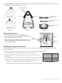
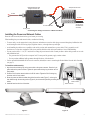
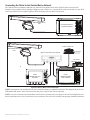
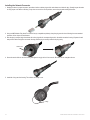
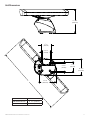
GMR™ 400/600/1200 xHD Radar Installation Instructions
Properly install your GMR 400/600/1200 xHD radar according to the following instructions. If you experience difficulty installing the
chartplotter, seek the assistance of a professional installer, or contact Garmin® Product Support.
Before installing your GMR 400/600/1200 xHD radar, confirm that the package contains the items listed on the box. If any parts are missing,
contact your Garmin dealer immediately.
Warning: Always wear safety goggles, ear protection, and a dust mask when drilling, cutting, or sanding.
Warning: The selected radar mounting location must be able to hold the weight of the radar and withstand any inertial forces.
Warning: The radar transmits electromagnetic energy. It is important that the radar is turned off or the DC power input is disconnected when
personnel are required to come close to the radar to perform work on the radar assembly or associated equipment. Electromagnetic energy is harmful.
CAUTION: When the radar is transmitting, do not look directly at the antenna at close range, because the eyes are the most sensitive part of the body to
electromagnetic energy.
Notice: When drilling or cutting, always check the opposite side of the drilling or cutting surface.
Product Registration
Help us better support you by completing our online registration today. Go to http://my.garmin.com. Keep the original sales receipt, or a
photocopy, in a safe place.
Contact Garmin
Contact Garmin Product Support if you have any questions while installing your GMR 400/600/1200 xHD radar. In the USA, go to
www.garmin.com/support, or contact Garmin USA by phone at (913) 397.8200 or (800) 800.1020.
In the UK, contact Garmin (Europe) Ltd. by phone at 0808 2380000.
In Europe, go to www.garmin.com/support and click Contact Support for in-country support information, or contact Garmin (Europe) Ltd. by
phone at +44 (0) 870.8501241.
Needed Tools
For Installing the Radar:
•
•
•
•
#2 Phillips screwdriver
5 mm Allen wrench
Drill and drill bits
Wrench and socket set
For Installing the Optional Field-Installable RJ-45 Network Connector:
•
•
•
•
Knife
Pliers
15 mm wrench
AMP modular-plug hand tool and die set or compatible equivalent
September 2012
190-01266-02 Rev. D
Printed in Taiwan
Selecting a Location
When selecting a location to install the GMR 400/600/1200 xHD radar, consider the following:
• An ideal mounting location is high above the keel line of the ship with a minimal part of the structure or rigging blocking the radar beam.
Obstructions in the path of the radar beam may cause blind and shadow sectors, or generate false echoes. The higher the installation position,
the farther the radar can detect targets.
• Avoid mounting on the same level as smoke stacks, horizontal spreaders, or crosstrees on a mast.
• Do not install the radar near heat sources where it may be exposed to smoke or hot air from smoke stacks or heat from lights.
• The mounting surface or platform should be sturdy enough to support the weight of the radar and any inertial forces, as flat as possible, and
parallel with the water line.
• Garmin recommends mounting the radar out of range of personnel (vertical beam width above head height). When properly installed and
operated, the use of this radar conforms to the requirements of ANSI/IEEE C95.1-1992 Standard for Safety Levels with Respect to Human
Exposure to Radio Frequency Electromagnetic Fields.
IEC 60936-1 clause 3-27.1 states maximum distances from the antenna at which Radio Frequency (RF) levels can be expected.
◦◦
◦◦
◦◦
◦◦
◦◦
◦◦
GMR 404 xHD (100W/m squared = 55 in. [1.4 m]) (10W/m squared = 178 in. [4.5 m])
GMR 406 xHD (100W/m squared = 65 in. [1.7 m]) (10W/m squared = 200 in. [5.1 m])
GMR 604 xHD (100W/m squared = 67 in. [1.7 m]) (10W/m squared = 217 in. [5.5 m])
GMR 606 xHD (100W/m squared = 79 in. [2 m]) (10W/m squared = 244 in. [6.2 m])
GMR 1204 xHD (100W/m squared = 99 in. [2.5 m]) (10W/m squared = 307 in. [7.8 m])
GMR 1206 xHD (100W/m squared = 111 in. [2.8 m]) (10W/m squared = 343 in. [8.7 m])
Caution: When the radar is transmitting, do not look directly at the antenna at close range (the eyes are the most sensitive part of the body to
electromagnetic energy).
• A compass safe distance must be maintained between the compass and the radar. The compass safe distance is measured from the center
point of the compass to the nearest point on the radar.
◦◦ Standard compass = 35 7/16 in. (90 cm)
◦◦ Standby Steering and Emergency compasses = 31 1/2 in. (80 cm)
• Mount other electronics and cables more than 7 ft. (2 m) from the path of a radar beam. A radar beam can spread 25° vertically above and
below the radiating element of the radar. For vessels with higher bow angles at cruise speed, you can lower the angle so that the beam points
slightly downward to the waterline while at rest. Shims may be used as necessary.
12.5°
12.5°
• Install the radar away from antennas or other electronics. GPS antennas should be located above or below the radar beam path of the radar.
Mount at least 3 ft. (1 m) from any equipment transmitting or cables carrying radio signals, such as VHF radios, cables, and antennas. In the
case of SSB radios, the distance should be increased to 7 ft. (2 m).
2
GMR 400/600/1200 xHD Installation Instructions
Installing the Mounting Studs and Seals
1. Remove the hatch on the front of pedestal by loosening the screw and lifting the hatch off of the hinges as shown in Figure 1.
2. Apply the included anti-seize compound to the threads of the four M10 x 71 mounting studs.
3. Use a 5 mm Allen wrench to install the M10 x 71 mounting studs (Figure 2) in the pedestal matching the hole pattern that was selected.
Tighten the mounting studs until they bottom out in the pedestal. Do not overtighten the studs to avoid damaging the pedestal. The mounting
studs have a thread-locking patch applied at the factory.
4. Install the seals onto the pedestal (Figure 3).
Figure 1
Figure 2
Figure 3
Important Steel-Structure Mounting Concerns
Notice: Improperly installing the radar on a steel surface will cause damage to the radar housing.
The radar housing will become corroded when improperly installed on a steel surface. To avoid corrosion of the radar housing, the housing
must be isolated from the steel surface using nylon washers, with enough space between the radar housing and the steel surface to allow water
to drain. Also, one of the four mounting studs must be properly connected to ground, and the ground connection must be properly isolated from
the steel surface with a nylon washer and coated with marine sealant (page 6).
Rubber seal
Steel surface
Nylon washers
Grounding wire (needed only
on one mounting stud)
Marine sealant
Mounting the Radar
Mount the radar with either end pointed toward the bow. Ensure it is mounted along the Bow-Stern Axis line indicated on the GMR
400/600/1200 Series Mounting Template. If the end with the hatch is pointed toward the bow, the Front of Boat Offset setting on the chartplotter
must be set to 180° (Figure 4). To adjust the Front of Boat Offset on the chartplotter, see page 8.
To mount the radar:
1. (Skip to step two if you are using a pre-drilled Garmin compatible Furuno® or Raymarine® mount.) Determine a suitable mounting location
and tape the Mounting Template in place. The Mounting Template has two hole patterns: Option A and Option B. Determine the most
appropriate patterns from the two patterns available on the Mounting Template (Option A or Option B). Use a 1/2 in. (13 mm) bit to drill the
four mounting holes.
2. Hoist the radar into position using the supplied strap. Position the strap over the ends of the antenna mount as shown in Figure 5. Ensure
that you position the strap as close to the radar as possible.
GMR 400/600/1200 xHD Installation Instructions
3
3. Fasten the radar to the mounting surface using the M10 hex nuts, spring washers, and flat washers in the order shown in Figure 6. The M10
nuts should be torqued to 130 lbf-in (11 lbf-ft) (1.5 kgf-m).
Bearing Offset = 0°
flat washer
Stern
Bow
Waveguide protective cover
spring washer
M10 hex nut
Bearing Offset = 180°
Figure 4
Figure 5
Figure 6
Mounting the Antenna
1. Remove the protective cover from the pedestal wave guide.
2. Verify that the antenna wave guide is aligned with the pedestal wave
guide. Slide the antenna onto the pedestal.
Align the
waveguide faces
3. Secure the antenna to the pedestal using the 8 mm hex bolts, flat
washers, and spring washers. The 8 mm bolts should be torqued to
70 lbf-in (6 lbf-ft) (.81 kgf-m).
Antenna
Pedestal
Installing the Voltage Converter Unit
The included voltage converter unit is needed to supply a specific constant voltage to the radar. When installing the voltage converter unit,
consider the following:
• The voltage converter requires an input voltage of 10–40 Vdc (20–40 Vdc for the GMR 1204 and GMR 1206).
• You must connect the converter to the boat battery through a 15 A slow-blow fuse.
Distance
Gauge
• Garmin recommends that you install the voltage converter as close as possible to the selected
9 ft. 10 in. (3 m)
12 AWG
power source.
16 ft. 4 in. (5 m)
10 AWG
• For optimal performance, connect the voltage converter housing to the RF ground of the vessel.
21 ft. 3 in. (6.5 m)
9 AWG
• If the input wires need to be extended, follow the recommendations in the wire gauge table.
26 ft. 2 in. (8 m)
8 AWG
◦◦ If the wires are extended, use the supplied heat-shrink butt connectors.
Wire Gauge Table
◦◦ After the connector is crimped, heat the connector to shrink it and provide a water resistant fit.
4
GMR 400/600/1200 xHD Installation Instructions
GMR 400/600/1200 xHD
Voltage Converter Unit
+
Sample boat fuse block
To radar
Voltage Converter Unit
To power
15 A slow-blow fuse
10–40 Vdc
(20–40 Vdc for
the GMR 1204
and 1206)
-
To RF ground
Connecting the Voltage Converter to a Boat Fuse Block
Installing the Power and Network Cables
Route the cable as needed, based on the type of mount you are using.
When installing the power and network cables, consider the following:
• To ensure safety, use the appropriate tie-wraps, fasteners, and sealant to secure the cable along a route and through any bulkhead or deck.
Avoid running the cable near moving objects, high-heat sources, or through doorways and bilges.
• Avoid installing the cable next to or parallel to other cables, such as radio antenna lines or power cables. This is essential to avoid
interference to or from other equipment. If this is not possible, shield the cable with metal conduit or a form of EMI shielding.
• You may need to drill a 1 1/4 in. (31.7 mm) hole for routing the power/network cable. Garmin provides a rubber cable grommet to cover the
cable installation hole.
◦◦ The grommet does NOT provide a waterproof seal. To waterproof the grommet, apply a marine sealant.
◦◦ You can purchase additional cable grommets through Garmin or a Garmin dealer.
• Use the optional field-installable RJ-45 network connector (included) to create a custom-length Garmin Marine Network cable if needed
(see page 9).
To install the cable assembly:
1. Align the notch and locking ring on the power cable to the power connector. Press the 2-pin
power cable to the power connector. Tighten the power-cable locking ring clockwise until it is
firmly sealed..
2. Press the RJ-45 marine network cable to the RJ-45 socket. Tighten the RJ-45 locking ring
clockwise until it is firmly sealed.
3. Route the power and network cables through the front of the radar (Figure 7), or through a
hole drilled through the mounting surface (Figure 8). Avoid excessively bending or twisting the
cables.
4. Install the hatch on the front of the radar.
Figure 7
GMR 400/600/1200 xHD Installation Instructions
RJ-45 network
cable connector
Power connector
Figure 8
5
Connecting the Radar to Power Through the Voltage Converter
Connect the radar power cable (red and black) to the voltage converter output cable (red and black) using the supplied heat-shrink crimp
connectors. After crimping the connections, heat the connectors to shrink the housing for a water resistant fit.
Notice: If you choose to cut the radar power cable, you must reconnect the in-line fuse holder.
Connect the radar to the water ground of the vessel using an 8 gauge copper cable (not included). Secure the ground wire to the radar housing
using one of the four mounting studs, an M10 nut, and flat washer. Cover the ground-wire connection, mounting stud, and nut in marine sealant.
GMR 400/600/1200 xHD radar
Garmin marine network cable
Radar power cable
7.5 A fuse
Power converter
+
-
To water ground
10–40 Vdc
(20–40 Vdc for
the GMR 1204
and 1206)
To RF ground
Power Wiring Diagram
6
GMR 400/600/1200 xHD Installation Instructions
Connecting the Radar to the Garmin Marine Network
For a stand-alone network (chartplotter and radar only), attach the RJ-45 marine network cable to the RJ-45 socket on the back of the
chartplotter. For an expanded network (including a chartplotter, radar, a GMS 10, etc.), attach the RJ-45 marine network cable to an open RJ-45
socket on the GMS 10 network expander. Tighten the RJ-45 locking ring clockwise until it is firmly sealed.
GMR 400/600/1200 xHD
radar
Garmin Marine Networkcompatible chartplotter
Stand-Alone Garmin Marine Network Example
GSD 22 sounder unit
GMR 400/600/1200 xHD
radar
xxxx
GMS 10 marine network port expander
To transducer
x x x x xxxxxxxxxxxxxxxxxxx
GDL 30/30A
XM weather receiver
Garmin
GPSMAP 3000 series
chartplotter
Garmin
GPSMAP 4000/5000
series chartplotter
Expanded Garmin Marine Network Example
NOTE: Each component of the expanded network must be installed according to its installation instructions. These diagrams only show how a
GMR 404/406 radar interacts with a network and do not show proper wiring for other network components.
NOTE: Every device connected to the Garmin Marine Network must be connected to the power supply for the boat. These diagrams show the
network connections; however, they do not show the power connections. Wire each device according to the appropriate installation instructions.
GMR 400/600/1200 xHD Installation Instructions
7
Configuring the Radar
After you install the radar, you must prepare the chartplotter or the Garmin Marine network to properly use the radar.
1. Update the chartplotter or Garmin Marine Network software.
2. Enter the radar antenna size.
3. Set the Front of Boat Offset if necessary.
Updating the Chartplotter or the Garmin Marine Network
If you have a GPSMAP 4000, 5000, 6000, 7000, or 700 series chartplotter, use a blank SD card to update the chartplotter or the network
according to the instructions in the chartplotter owner’s manual.
If you have a GPSMAP 3000 series chartplotter, use a blank Garmin Data Card to update the chartplotter or the network according to the
instructions in the chartplotter owner’s manual.
Download the latest software from www.garmin.com.
Entering the Radar Antenna Size
Using a chartplotter, specify the size of your radar antenna (4 foot or 6 foot). Until you specify the antenna size, the warning “Radar Needs
Configured” appears on the chartplotter.
NOTE: Ensure you specify the correct antenna size on your chartplotter to obtain optimum performance.
To enter the radar antenna size on a GPSMAP 4000,5000, 6000, 7000, or 700 series chartplotter:
1. From the Home screen, select Radar.
2 From the Radar screen, select Menu > Radar Setup > Antenna Size.
3. Select the correct antenna size, 4 foot or 6 foot.
To enter the radar antenna size on a GPSMAP 3000 series chartplotter:
1. Press the PAGE key to switch to the Radar page.
2. Press the Setup softkey to open the setup page.
3. Using the ROCKER, highlight the Advanced tab, then the Antenna Size field, and press ENTER.
4. Select the correct antenna size, 4 foot or 6 foot, and press ENTER.
Changing the Front of Boat Offset
To measure potential radar offset:
1. Using a magnetic compass, take an optical bearing of a stationary target located within viewable range.
2. Measure the target bearing on the radar.
3. If the bearing deviation is more than +/- 1°, further correct the Front of Boat Offset.
bow
To change the Front of Boat Offset on a GPSMAP 4000, 5000, 6000, 7000, or 700 series
chartplotter:
1. From the Home screen, select Radar.
2. From the Radar screen, select Radar Setup > Front of Boat.
3. Enter an offset value, then select Back.
To change the Front of Boat Offset on a GPSMAP 3000 series chartplotter:
1. From the Radar page, press the Setup softkey to open the setup page.
2. From the Setup page, using the ROCKER, select the Advanced tab.
3. Highlight the Front of Boat Offset slider, and press ENTER.
4. Adjust the value accordingly. The preview window changes as you adjust the slider.
5. After an offset is determined, press ENTER to save, and press QUIT to return to the Radar page.
8
Front of Boat Offset = 0°
stern
Depending on the radar installation, you may need to change the Front of Boat Offset. If the radar installation
requires a 180° offset, change the Front of Boat Offset to 180° and test the radar. If the Front of Boat Offset
needs further adjustment, measure the radar offset and change the offset using the following procedures.
Front of boat Offset = 180°
GMR 400/600/1200 xHD Installation Instructions
Installing the Field-Installable RJ-45 Network Connector (Optional)
A field-installable RJ-45 network connector is provided for you to create a network cable that is the correct length for your installation.
➊ O-Ring
➋ RJ-45 modular plug
➌ Ethernet cable termination
➌
Copper tape strip (not shown)
➊
➋
Preparing the Network Cable
1. Cleanly cut your Ethernet cable to the desired length. Retain the cut RJ-45 connector for Step 4.
2. Remove the strain-relief nut from the cable-connection housing and slide it onto the cut end of the cable as shown.
3. Feed the cut cable end through the connection housing as shown.
Cut end of cable
Strain relief
Connection
housing
4. Examine the RJ-45 connector removed in Step 1 and compare it to the wire positions in the table below. Note which cable side, A or B, was
removed in Step 1.
Position
Wire Color—Main/Stripe
Side A
Side B
1
White/Orange
White/Green
2
Orange
Green
3
White/Green
White/Orange
4
Blue
Blue
5
White/Blue
White/Blue
6
Green
Orange
7
White/Brown
White/Brown
8
Brown
Brown
Position 8
Position 1
NOTE: The Garmin Marine Network requires cross-over cables not exceeding 100 meters between devices. When constructing a custom cable
from bulk wire, you must create both a Side A and Side B.
5. Prepare the cable for plug installation:
• Using a sharp knife, insert the blade between the cable shield and jacket. Slit the jacket 5/8" back from the
trimmed end of the cable.
9/16 in.
(14 mm)
• Peel the jacket back and remove the slit portion.
• Trim the shield and Mylar film away from wires. Be careful not to cut any of the wires.
• Fold the drain wire back over the jacket and trim to approximately 9/16 in. (14 mm).
• Untwist the wire pairs enough to ensure a proper connection.
Drain
• Arrange individual wires in proper order according to the table shown above. For example, if you have identified
wire
the end of the cable in Step 4 as Side A, arrange the wires for Side A. If you are constructing a custom cable
from bulk wire, you need to make both a Side A and a Side B connection.
• Trim the wire ends to an even length, leaving approximately 9/16 in. (14 mm) from the ends to the jacket edge.
• Place the drain wire on the jacket. Wrap the supplied copper tape around cable as close to the edge of the jacket as possible.
• Using a pair of pliers, squeeze the copper tape to pre-form the cable jacket end for easier insertion into the plug. Use caution to avoid
damaging the copper tape.
GMR 400/600/1200 xHD Installation Instructions
9
Installing the Network Connector
1. Keeping the wires in proper sequence, insert them into the modular plug until the ends bottom out inside the plug. Visually inspect the wires
to verify proper order before continuing. If any wires are not in the correct position, remove the plug and rearrange the wires.
2. Using an AMP Modular Plug Hand Tool and Die Set (or compatible equivalent), crimp the plug onto the wires following the recommended
procedure of the crimp-tool manufacturer.
3. After the plug is crimped, align the release tab on the plug with the corresponding notch in the cable-connection housing. Depress the tab
and push the cable through the connection housing until the plug is securely seated in the plug cavity.
Release tab
4. Screw the strain relief nut onto the housing and tighten it snugly with a 15 mm wrench. Be careful not to overtighten the nut.
5. Install the O-ring onto the housing. The cable is now ready to use.
O-Ring
10 GMR 400/600/1200 xHD Installation Instructions
Unit Dimensions
17 11/32 in.
(440.8 mm)
7 7/8 in.
(200 mm)
5 29/32 in.
(150 mm)
5 33/64 in.
(140 mm)
L
7 7/8 in.
(200 mm)
12 11/32 in.
(313.5 mm)
12 7/8 in.
(326.8 mm)
Model
L
GMR 404/604/1204 xHD
51 19/32 in. (1310 mm)
GMR 406/606/1206 xHD
75 45/64 in. (1923 mm)
GMR 400/600/1200 xHD Installation Instructions
11
Specifications
Pedestal (Physical)
Weight: 45.9 lb. (20.82 kg)
Power Cable: 49 ft. 2 35/64 in. (15 m) long
Network Cable: 49 ft. 2 35/64 in. (15 m) long
GMR 400/600 xHD
Transmit Power: GMR 400 xHD: 4 kW
Transmit Power: GMR 600 xHD: 6 kW
Transmitter Frequency: 9410 ±30 MHz
Input Voltage: 10–40 Vdc (with the Voltage
Converter Unit)
Typical Input Power: 55 W
Input Power (100 kn wind):
145 W max
Range/Pulse Width/PRF (nm/nsec/Hz):
0.125 – 0.5/75/3980
0.750 - 1/185/3975
1.5/235/3200
2.0/283/2750
3.0/370/1970
4.0/440/1736
6.0 – 12/535/1407
16 – 36/1032/800
48 – 72/1032/500
Antenna Rotation: 24 rpm and 48 rpm
Max wind load: 100 knots
Receiver Noise Figure: Less than 4 dB
Environmental:
Temp: from 14 to 140º F
(from -10 to +60º C)
Humidity: 95% at 95º F (35º C)
Rel Wind: 100 kn
Waterproof to IEC 60529 IPX6
Range: 65.5 ft. (20 m) mini, 72 nm max
Range discrimination: 65.5 ft. (20 m)
Radar interference: Anti-jamming algorithm
Clutter suppression: Sea clutter and rain clutter
GMR 1200 xHD
Transmit Power: 12 kW
Transmitter Frequency: 9410 ±30 MHz
Input Voltage: 20–40 Vdc (with the Voltage
Converter Unit)
Typical Input Power: 65 W
Input Power (100 kn wind):
155 W max
12 Range/Pulse Width/PRF (nm/nsec/Hz):
0.125 – 0.5/75/3980
0.750 - 1/185/3975
1.5/235/3200
2.0/283/2750
3.0/370/1970
4.0/440/1736
6.0 – 12/535/1407
16 – 36/1032/800
48 – 72/1032/500
Antenna Rotation: 24 rpm and 48 rpm
Max wind load: 100 knots
Receiver Noise Figure: Less than 4 dB
Environmental:
Temp: from 14 to 140º F
(from -10 to +60º C)
Humidity: 95% at 95º F (35º C)
Rel Wind: 100 kn
Waterproof to IEC 60529 IPX6
Range: 65.5 ft. (20 m) min, 72 nm max
Range discrimination: 65.5 ft. (20 m)
Radar interference: Anti-jamming algorithm
Clutter suppression: Sea clutter and rain clutter
4 ft Open-Array Antenna
Type: End-fed slotted waveguide
Horizontal Beamwidth: 1.8 degrees
Horizontal Sidelobes:
-23 dB within ±10 degrees of main
-30 dB outside ±10 degrees of main
Vertical Beamwidth: 24 degrees
Antenna Gain: 29 dB
Polarization: Horizontal
Input Return Loss: Better than -20 dB
Weight: 12.2 lb. (5.53 kg)
6 ft. Open-Array Antenna
Type: End-fed slotted waveguide
Horizontal Beamwidth: 1.1 degrees
Horizontal Sidelobes:
-25 dB within ±10 degrees of main
-30 dB outside ±10 degrees of main
Vertical Beamwidth: 24 degrees
Antenna Gain: 30 dB
Polarization: Horizontal
Input Return Loss: Better than -20 dB
Weight: 16.9 lb. (7.67 kg)
Radar Display Features
Presentation Modes: North up, Course up,
Heading up
VRM/EBL: 1 user adjustable (GPSMAP
4000/5000/6000/7000/700 series
chartplotters)
2 user adjustable, capable of floating
(GPSMAP 3000 series chartplotters)
Bearing Accuracy: 1 degree
Controls: Auto & manual gain adjust; manual or
auto (AFC) receiver tuning;
manual adjust for rain clutter and for sea
clutter.
Radar/Chart Overlay: Overlay mode is
supported. Also has split overlay with
standard radar presentation
Harbor Mode: Optimized radar performance in
the harbor
Offshore Mode: Optimized radar performance
offshore
Dual Range Mode: Simultaneous operation of
two ranges displayed in split screen format
User selectable ranges of 1/8 nm to 3 nm on
left side and 1/8 nm to 72 nm on right side
Timed Transmit: (GPSMAP 3000 series
chartplotters) user-specified transmission and
standby time.
Sentry: (GPSMAP 4000/5000/6000/7000/700
series chartplotters) user-adjustable timedtransmit mode
Zoom Mode: 2x, 4x (GPSMAP 3000 series
chartplotters only)
Trails (Wakes): Short, Medium, Long (GPSMAP
3000 series chartplotters only)
Guard Zone Alarm: 2 guard zones—user
adjustable
Off center Function: Look ahead (GPSMAP
4000/5000/6000/7000/700 series
chartplotters)
Look ahead, Auto Shift and Manual
(GPSMAP 3000 series chartplotters)
Antenna RPM: Selectable to 24 or 48 rpm
MARPA: Tracks up to 10 MARPA targets for
radar plotting and collision avoidance
(Heading sensor is required)
GMR 400/600/1200 xHD Installation Instructions
Warnings
Failure to avoid the following potentially hazardous situations could result in
an accident or collision resulting in death or serious injury.
• The radar transmits electromagnetic energy. Ensure that the radar has been
installed according to the recommendations given in this guide, and that all
personnel are clear of the radar before switching to transmit mode.
• When navigating, carefully compare information displayed on the unit to all
available navigation sources, including information from visual sightings,
and maps. For safety, always resolve any discrepancies or questions before
continuing navigation.
• Use the electronic chart in the unit only to facilitate, not to replace, the use
of authorized government charts. Official government charts and notices to
mariners contain all information needed to navigate safely.
• Use this unit only as a navigational aid. Do not attempt to use the unit for any
purpose requiring precise measurement of direction, distance, location, or
topography.
WARNING: This product, its packaging, and its components contain chemicals known to the State of California to cause cancer, birth defects, or reproductive harm. This
Notice is provided in accordance with California’s Proposition 65. See www.garmin.com/prop65 for more information.
WARNING: Do not cut the fuse holder from the red wire. The fuse holder must remain in place for the Garmin radar to function correctly. Removing the inline fuse holder
may damage your boat's circuitry.
CAUTION: Check with local authorities for any operational restrictions or licensing requirements that may apply while using this device.
CAUTION: Do not use the GMR 400/600/1200 xHD radar on inland Belgium waters because the radars exceed authorized Belgian power transmission levels for inland
waters.
FCC Compliance
The GMR 400/600/1200 xHD radar complies with Part 80 of the FCC rules. It has received a grant of equipment authorization, issued under the
authority of the FCC.
This equipment generates, uses, and can radiate radio frequency energy and, if not installed and used in accordance with the instructions, may
cause harmful interference to radio communications. However, there is no guarantee that interference will not occur in a particular installation.
If this equipment does cause harmful interference to radio or television reception, which can be determined by turning the equipment off and
on, the user is encouraged to try to correct the interference by one of the following measures:
•
•
•
•
Reorient or relocate the receiving antenna.
Increase the separation between the equipment and the receiver.
Connect the equipment into an outlet on a circuit different from that to which the receiver is connected.
Consult the dealer or an experienced radio/TV technician for help.
Industry Canada Compliance
The GMR 400/600/1200 xHD radar complies with Industry Canada Standard RSS-138.
Declaration of Conformity (DoC)
Hereby, Garmin, declares that this product is in compliance with the essential requirements and other relevant provisions of Directive 1999/5/
EC. To view the full Declaration of Conformity, go to www.garmin.com/compliance.
Software License Agreement
BY USING THE GARMIN 600/1200 SERIES RADAR, YOU AGREE TO BE BOUND BY THE TERMS AND CONDITIONS OF THE
FOLLOWING SOFTWARE LICENSE AGREEMENT. PLEASE READ THIS AGREEMENT CAREFULLY.
Garmin grants you a limited license to use the software embedded in this device (the “Software”) in binary executable form in the normal
operation of the product. Title, ownership rights, and intellectual property rights in and to the Software remain in Garmin.
You acknowledge that the Software is the property of Garmin and is protected under the United States of America copyright laws and
international copyright treaties. You further acknowledge that the structure, organization, and code of the Software are valuable trade secrets of
Garmin and that the Software in source code form remains a valuable trade secret of Garmin. You agree not to decompile, disassemble, modify,
reverse assemble, reverse engineer, or reduce to human readable form the Software or any part thereof or create any derivative works based on
the Software. You agree not to export or re-export the Software to any country in violation of the export control laws of the United States of
America.
GMR 400/600/1200 xHD Installation Instructions
13
Limited Warranty
This Garmin product is warranted to be free from defects in materials or workmanship for one year from the date of purchase. Within this
period, Garmin will, at its sole option, repair or replace any components that fail in normal use. Such repairs or replacement will be made at
no charge to the customer for parts or labor, provided that the customer shall be responsible for any transportation cost. This warranty does not
apply to: (i) cosmetic damage, such as scratches, nicks and dents; (ii) consumable parts, such as batteries, unless product damage has occurred
due to a defect in materials or workmanship; (iii) damage caused by accident, abuse, misuse, water, flood, fire, or other acts of nature or external
causes; (iv) damage caused by service performed by anyone who is not an authorized service provider of Garmin; or (v) damage to a product
that has been modified or altered without the written permission of Garmin. In addition, Garmin reserves the right to refuse warranty claims
against products or services that are obtained and/or used in contravention of the laws of any country.
This product is intended to be used only as a travel aid and must not be used for any purpose requiring precise measurement of direction,
distance, location or topography. Garmin makes no warranty as to the accuracy or completeness of map data in this product.
THE WARRANTIES AND REMEDIES CONTAINED HEREIN ARE EXCLUSIVE AND IN LIEU OF ALL OTHER WARRANTIES
EXPRESS, IMPLIED, OR STATUTORY, INCLUDING ANY LIABILITY ARISING UNDER ANY WARRANTY OF MERCHANTABILITY
OR FITNESS FOR A PARTICULAR PURPOSE, STATUTORY OR OTHERWISE. THIS WARRANTY GIVES YOU SPECIFIC LEGAL
RIGHTS, WHICH MAY VARY FROM STATE TO STATE.
IN NO EVENT SHALL GARMIN BE LIABLE FOR ANY INCIDENTAL, SPECIAL, INDIRECT OR CONSEQUENTIAL DAMAGES,
INCLUDING, WITHOUT LIMITATION, DAMAGES FOR ANY TRAFFIC FINES OR CITATIONS, WHETHER RESULTING FROM THE
USE, MISUSE OR INABILITY TO USE THE PRODUCT OR FROM DEFECTS IN THE PRODUCT. SOME STATES DO NOT ALLOW
THE EXCLUSION OF INCIDENTAL OR CONSEQUENTIAL DAMAGES, SO THE ABOVE LIMITATIONS MAY NOT APPLY TO YOU.
Garmin retains the exclusive right to repair or replace (with a new or newly-overhauled replacement product) the device or software or offer a
full refund of the purchase price at its sole discretion. SUCH REMEDY SHALL BE YOUR SOLE AND EXCLUSIVE REMEDY FOR ANY
BREACH OF WARRANTY.
To obtain warranty service, contact your local Garmin authorized dealer or call Garmin Product Support for shipping instructions and an RMA
tracking number. Securely pack the device and a copy of the original sales receipt, which is required as the proof of purchase for warranty
repairs. Write the tracking number clearly on the outside of the package. Send the device, freight charges prepaid, to any Garmin warranty
service station.
Online Auction Purchases: Products purchased through online auctions are not eligible for warranty coverage. Online auction confirmations
are not accepted for warranty verification. To obtain warranty service, an original or copy of the sales receipt from the original retailer is
required. Garmin will not replace missing components from any package purchased through an online auction.
International Purchases: A separate warranty may be provided by international distributors for devices purchased outside the United States
depending on the country. If applicable, this warranty is provided by the local in-country distributor and this distributor provides local service
for your device. Distributor warranties are only valid in the area of intended distribution. Devices purchased in the United States or Canada
must be returned to the Garmin service center in the United Kingdom, the United States, Canada, or Taiwan for service.
Australian Purchases: Our goods come with guarantees that cannot be excluded under the Australian Consumer Law. You are entitled to a
replacement or refund for a major failure and for compensation for any other reasonably foreseeable loss or damage. You are also entitled to
have the goods repaired or replaced if the goods fail to be of acceptable quality and the failure does not amount to a major failure. The benefits
under our Limited Warranty are in addition to other rights and remedies under applicable law in relation to the products.
Garmin Australasia
Unit 19, 167 Prospect Highway
Seven Hills, NSW, Australia, 2147
Phone: 1800 822 235
Garmin’s Marine Warranty Policy: Certain Garmin Marine products in certain areas have a longer warranty period and additional terms
and conditions. Go to www.garmin.com/support/warranty.html for more details and to see if your product is covered under Garmin’s Marine
Warranty Policy.
14 GMR 400/600/1200 xHD Installation Instructions
GMR 400/600/1200 xHD Installation Instructions
15
All rights reserved. Except as expressly provided herein, no part of this manual may be reproduced, copied, transmitted, disseminated, downloaded or stored in any storage
medium, for any purpose without the express prior written consent of Garmin. Garmin hereby grants permission to download a single copy of this manual onto a hard drive or
other electronic storage medium to be viewed and to print one copy of this manual or of any revision hereto, provided that such electronic or printed copy of this manual must
contain the complete text of this copyright notice and provided further that any unauthorized commercial distribution of this manual or any revision hereto is strictly prohibited.
Information in this document is subject to change without notice. Garmin reserves the right to change or improve its products and to make changes in the content without
obligation to notify any person or organization of such changes or improvements. Visit the Garmin Web site (www.garmin.com) for current updates and supplemental
information concerning the use and operation of this and other Garmin products.
Garmin®, the Garmin logo, and GPSMAP® are trademarks of Garmin Ltd. or its subsidiaries, registered in the USA and other countries. GMR™ and myGarmin™ are
trademarks of Garmin Ltd. or its subsidiaries. These trademarks may not be used without the express permission of Garmin.
Furuno® is a registered trademark of Furuno Electric Co., Ltd. Raymarine® is a registered trademark of Raymarine Limited.
For the latest free software updates (excluding map data) throughout the life of your
Garmin products, visit the Garmin Web site at www.garmin.com.
© 2010–2012 Garmin Ltd. or its subsidiaries
Garmin International, Inc.
1200 East 151st Street, Olathe, Kansas 66062, USA
Garmin (Europe) Ltd.
Liberty House, Hounsdown Business Park, Southampton, Hampshire, SO40 9LR UK
Garmin Corporation
No. 68, Zhangshu 2nd Road, Xizhi Dist., New Taipei City, 221, Taiwan (R.O.C.)
www.garmin.com
September 2012
190-01266-02 Rev. D
Printed in Taiwan