1
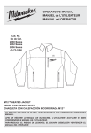
OPERATOR’S MANUAL
Cat. No.
2260-21
M12™ 160x120 Thermal Imager
To reduce the risk of injury, user must read and understand
operator’s manual.
Contents
Safety Information ................................................................................................................................. 1
Introduction............................................................................................................................................. 3
How to Use the Manuals........................................................................................................................ 4
Obtaining Technical Support or Service ................................................................................................ 5
Unpacking the System........................................................................................................................... 6
Charging and Installing the Battery........................................................................................................ 8
Installing the SD Memory Card.............................................................................................................. 8
Controls and Features............................................................................................................................ 9
Battery Life and Power-Saving Features.............................................................................................. 13
Taking a Basic Thermal Picture............................................................................................................ 14
Using the Built-In Visual Image Camera............................................................................................... 16
Reviewing Saved Images..................................................................................................................... 16
Optimizing Thermal Images.................................................................................................................. 17
Manual Range and Auto Range........................................................................................................... 19
Changing the Color Palette.................................................................................................................. 21
Changing the Settings.......................................................................................................................... 22
Specifications....................................................................................................................................... 23
Glossary............................................................................................................................................... 25
M12 160x120 Thermal Imager Operator’s Manual
Safety Information
WARNING
READ ALL SAFETY WARNINGS AND INSTRUCTIONS
Failure to follow the warnings and instructions may result in electric shock, fire and/or serious injury. Save these instructions - This
OPERATOR’S MANUAL contains important safety and operating instructions for this Thermal Imager. Before using the Thermal Imager, read
this OPERATOR’S MANUAL, the M12 Battery Charger and Battery OPERATOR’S MANUAL, and all labels on the battery pack, charger and
Thermal Imager.
•
Avoid dangerous environments. Do not use in rain, snow, damp or wet locations. Do not use in the presence of explosive atmospheres (gaseous
fumes, dust or flammable materials) because sparks may be generated when inserting or removing battery pack, possibly causing fire or explosion.
Battery Use and Care
•
Recharge only with the charger specified by the manufacturer. A charger that is suitable for one type of battery pack may create a risk of fire
when used with another battery pack.
•
Use power tools only with specifically designated battery packs. Use of any other battery packs may create a risk of injury and fire.
•
When battery pack is not in use, keep it away from other metal objects like paper clips, coins, keys, nails, screws, or other small metal
objects that can make a connection from one terminal to another. Shorting the battery terminals together may cause burns or a fire.
Service
•
Have your Thermal Imager serviced by a qualified repair person using only identical replacement parts. This will ensure that the safety of
the tool is maintained. MILWAUKEE Tool Company recommends service and calibration at a MILWAUKEE Service Center annually.
•
Do not disassemble. Incorrect reassembly may result in the risk of electric shock or fire. If it is damaged, take it to a MILWAUKEE service facility.
•
Store in a cool, dry place. Do not store where temperatures may exceed 120 °F (50 °C) such as in direct sunlight, a vehicle or metal building
during the summer.
•
Do not remove or deface labels. Maintain labels and nameplates. These carry important information. If unreadable or missing, contact a
MILWAUKEE service facility for a free replacement.
M12 160x120 Thermal Imager Operator's Manual
1
Federal Communications Commission WARNING: Changes or modifications to this unit not expressly approved by the party responsible for compliance
could void the user’s authority to operate the equipment. This equipment has been tested and found to comply with the limits for a Class B digital
device, pursuant to Part 15 of the FCC Rules. These limits are designed to provide reasonable protection against harmful interference in a residential
installation. This equipment generates, uses and can radiate radio frequency energy and, if not installed and used in accordance with the instructions,
may cause harmful interference to radio communications. However, there is no guarantee that interference will not occur in a particular installation. If this
equipment does cause harmful interference to radio or television reception, which can be determined by turning the equipment off and on, the user is
encouraged to try to correct the interference by one or more of the following measures:
• Reorient or relocate the receiving antenna.
• Increase the separation between the equipment and receiver.
• Connect the equipment into an outlet on a circuit different from that to which the receiver is connected.
• Consult the dealer or an experienced radio/TV technician for help.
2
M12 160x120 Thermal Imager Operator’s Manual
Introduction
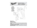
Model 2260-21 M12™ 160x120 Thermal Imager is an
ultra-rugged, hand-held battery-powered tool that takes
thermal pictures, called “thermal images.” Thermal images
reveal different temperatures as different colors. A bright
color display shows an image of hot and cold spots and
temperature gradients in-between. The temperature of the
object in the center target is shown at the top of the thermal
image. Information about the temperature range and color
palette settings for the image are on the bottom of the
image. See Figure 1.
You can optionally load the thermal images onto a
computer to prepare a report later. The Thermal Imager
and its supplied PC software satisfy the requirements
of industrial electricians and technicians new to thermal
imaging, as well as expert professional thermographers.
174.3˚F
MILWAUKEE Thermal Imager Report Software is included
on the CD (Compact Disk). Instructions for using the
software are in the MILWAUKEE Thermal Imager Report
Software Manual, which is on the supplied CD.
With the software, you can organize, choose, annotate
and adjust images and present results in a report. In your
report, you can write recommendations and add your
company logo.
98
226
Figure 1. Thermal Imager and a Thermal Image
M12 160x120 Thermal Imager Operator's Manual
3
How to Use the Manuals
All of the manuals needed to safely and properly operate
the Thermal Imager are available in Adobe® PDF (Portable
Document Format) on the CD. You can easily load these
PDF documents from the CD or from the MILWAUKEE
website onto your computer. There, you read them on the
computer screen, search for topics or keywords, or print
pages from them.
NOTE
To open and read the PDF manuals, your PC uses
Adobe® Acrobat®. If your PC does not already have
Acrobat Reader, you can install it at no cost by
following the prompts on the PC when you run the
CD supplied with your Thermal Imager. Adobe®
and Adobe Reader® are registered trademarks of
Adobe Systems Incorporated in the United States
and other countries.
The following manuals are supplied with the Thermal
Imager:
M12 160x120 Thermal Imager Operator’s Manual:
this explains how to use the Thermal Imager. Thermal
Imager Specifications and a Glossary of Terms are
located at the back of this manual.
4
Thermal Imager Report Software Manual: this
explains how to use MILWAUKEE Thermal Imager
Report Software to produce a report. You load this
manual onto your computer from the product CD when
you install the software. It opens for viewing whenever
you press F1 or “Help” while using the software.
M12 Battery Charger and Battery Operator’s
Manual: this is a printed booklet that you should read
and understand before using the product. It contains
important warnings and information for proper battery
handling and charging. Improper usage, handling or
charging of the batteries can cause risk of fire or injury.
You must first charge the battery before you use the
Thermal Imager.
Warranty and Safety Information: this is a printed
booklet with the Warranty, safety information from
the Operator’s Manuals for the battery, charger and
Thermal Imager and an explanation of symbols on the
product and in the documentation.
Reference Card: this is a printed, folded, pocket-sized,
picture-based guide. It gives you visual step-by-step
instructions for basic workflow using with the Thermal
Imager system.
M12 160x120 Thermal Imager Operator’s Manual
Obtaining Technical Support or Service
Visit www.milwaukeetool.com online and click on Service.
There you can search for the nearest factory authorized
Service Center. You can also find how to contact someone
at MILWAUKEE by email, telephone, or postal mail.
NOTE
Always contact a Service Center first for
instructions and a return authorization number
(RMA) before you ship any product for service or
calibration.
The mailing address for the main MILWAUKEE Service
Center is:
MILWAUKEE Service Center
13145 West Lisbon Rd.
Brookfield, WI 53003
USA
M12 160x120 Thermal Imager Operator's Manual
5
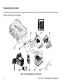
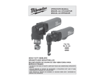
Unpacking the System
The complete system comes packed in a rugged portable hard case. Figure 2 and Table 1 identify each item. If anything is
missing, contact the point of purchase.
3
4
6
11
Y
NT TY N
RA FE IO
AR SA AT
W D RM
ANFO
IN
L
UR
UA ATE R
AN LIS DO
M
'S UTI RA
.
No t.
OR L' PE
t. Ca
AT de l O
Ca de 2401
0
ER EL de
No -59- -2
OP ANU UAL
48 2510
M AN
M
e
for
be
ed
le.
e
arg
ch
êtr initia ar
nt
be
rg
st
ive on ca
z.
n
do lisati
mu
be ve
s
es
'S
de era
rie
uv r uti
tte
se im
OR
ne leu
t
s
ba
AT
as r pr
EN
w use. rie an
ev
ER
BI
Ne rst
tte av
nu as po
OP
ba ées ías
fi
ET
EL
s
arl
ND
E
Le arg
ter us
ER
TA
LIR
ch s ba de
ND
RS
IT
V
TE
La tes
DE
12
DO
an
EN
UN
Y
D
DE
UR
AN
IO
ER
TE
LE
LIT
AD
ISA
RS
RE
BE
DE
TIL
GE
V
S
DE
ST
AR
L'U
12
NE
O
N
MU
CH
S,
RI
Y
-IO 12V DE IOV
RE
ER
UA
ER Y
SU .
UM N
12
US
TT ER
, US
AS
HI -IO
ES UR
EL
BA TT
BL TE
LIT UM TERÍ IO DEJURY
N BA
S,
IO
AU HI
IN
DE ISA NE
BA LIT
S LIT
TIL
Li- ION
OF
RA DE
V
UE L'U
SIO
12 V Li- GEUR AU PA S
LE
SQ
IE
S
NE RISK
RI DE DE
12
AR ER
E
EL
OR IO
LE
CH TT
TH
NU
GO
AD DE
E
BA RG RÍA
ES .
IR MA
CE
RI OR
DU LE
DU .
CA TE
EL AD
RÉ RE
RE AL
BA
TO NU DE ND CIROPER
MA IN
RE DU L
AF MP RE DE
CO RA AL
PA NU
MA
ION
markings
chargeur
du de PRECAUC
CAUTION
for le fond
mensajes
Vea
.
r
ge
T
2
5
7
16
0
12
0x
™
12
M
TO
AD
a
RE
Im
T
L.
al
US UA
M
erm
ER MAN
S
, US R’
RY TO
JU
IN PERA
O
OF
SK THIS
RI
E
ND
TH TA
CE RS
DU DE
UN
Th
RE
No t.
t. Ca
Ca de 2401
No -1148
of charger
GARDE los
EN
para
bottom
See le MISE
cargador
Voir del
el fondo
SD
USB 2.0
1
o.
. N -21
Cat 60
22
PRODUC
CD
rence
Refe ard
C
D
AN
SD CARD READER
8
10
9
Figure 2. Identifying Items in the Hard Case
6
M12 160x120 Thermal Imager Operator’s Manual
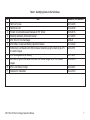
Table 1. Identifying Items in the Hard Case
No.
1
2
3
4
5
6
7
8
9
10
11
Item
Hard Carry Case
Reference Card
Product CD with software and manuals in PDF format
Warranty and Safety Information booklet
M12 160 x120 Thermal Imager
M12 Battery Charger and Battery Operator’s Manual
SD Memory Card Reader with USB (Universal Serial Bus) plug for attaching to a PC
to transfer images
M12 Rechargeable Li-Ion Battery
Mini USB to Type A USB cable to connect the Thermal Imager to a PC to transfer
images
M12 Li-Ion Battery Charger
Statement of Calibration
M12 160x120 Thermal Imager Operator's Manual
Model or Part Number
42-55-2265
58-22-0240
58-99-0015
22-74-3005
2260-20
58-14-2402
22-80-0110
48-11-2401
42-44-0205
48-59-2401
58-22-0190
7
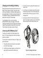
Charging and Installing the Battery
Read and understand the warnings and instructions in the
Battery Charger Operator’s Manual. Charge the battery
until the green indicator on the Battery Charger appears. It
takes approximately 30 minutes to reach a full charge with
the supplied M12 battery. Any MILWAUKEE M12 Series
battery will work with the Thermal Imager.
To avoid damage or injury, use only a genuine
MILWAUKEE M12 battery and charger, and follow the
charging and handling instructions supplied with the Battery
Charger. Snap the battery into place until it locks into the
Thermal Imager’s hand grip as shown in Figure 4.
3. To remove it, press it in gently and it releases so you
can pull it out.
4. If an SD card is not installed, insert the SD card with
the label facing the front of the Thermal Imager (the
side with the lens). It fits only one way. Do not use
excessive force.
5. Gently press it until the SD card clicks and locks in
place. Press it again to release it. Leave it locked into
place and close the rubber dust and water cover.
Accessing the SD Memory Card
The SD card is installed in the Thermal Imager at the
factory. The Thermal Imager does not store any images
without one installed.
To remove and re-install the SD card, refer to Figure 3 and
proceed as follows:
1. Flip open the rubber dust and water cover toward the
front of the Thermal Imager.
2. If an SD card is already installed, you will see it in the
upper half of the area under the rubber cover.
8
Figure 3. Installing the SD Card
M12 160x120 Thermal Imager Operator’s Manual
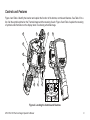
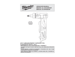
Controls and Features
Figure 4 and Table 2 identify the location and explain the function of the buttons, controls and features. See Table 3 for a
list of all the symbols printed on the Thermal Imager and the meaning of each. Figure 5 and Table 3 explain the meaning
of symbols and information on the display when it is showing a thermal image.
4
6
7
12
3
2
1
11
8
10
5
14
15
16
17
9
13
18
Figure 4. Locating the Controls and Features
M12 160x120 Thermal Imager Operator's Manual
9
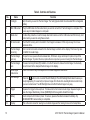
Table 2. Controls and Features
No.
1
Name
Hand grip
2
Mini USB socket
3
Media door
4
SD card socket
5
9
Thermal imager
focus ring
Thermal imager
lens cap
Thermal imager
lens
Visual digital
camera lens
LED flashlight
10
Trigger
11
Battery
12
Display
6
7
8
10
Function
Grip this when you use the Thermal Imager. The hand grip also holds the removable M12 rechargeable
battery.
Plug the USB cable into this socket when you want to connect the Thermal Imager to a computer. This
is one way to transfer images to a computer.
A rubber-flap protective cover that keeps dust and moisture out of the USB socket and SD memory card
socket when you are not using these sockets.
Push the SD memory card in to install it. Push it again to release it. It fits only one way. Do not use
excessive force.
Turn in small increments and wait for the thermal image to refresh on the display. This focus ring does
not affect the visual image.
To open for use, squeeze the side release tabs, lift the lens cap up and snap it in place on top of the
Thermal Imager. To protect the lens, replace the lens cap when you are not using the Thermal Imager.
Focuses incoming infrared (IR) radiation on to the IR sensor to make a thermal image. You manually
focus this lens for the sharpest thermal image on the display.
There is no need for any focus adjustment. All visual images are fixed-focus.
button to turn on and off the LED flashlight. The LED flashlight illuminates the area you
Press the
are photographing. It is used only to improve images from the built-in visual digital camera and to help
you see in a dark area. The LED flashlight does not affect thermal images in any way.
Squeeze the trigger to take a picture. This takes both a thermal and visual image. Squeeze it again to
save the image. Alternatively, choose [CANCEL] from the keypad to discard the image.
Insert and push until it locks in place. To remove, squeeze the sides to release the battery. Any
MILWAUKEE M12 series battery is compatible.
This is the color screen for viewing live or stored images and for making choices in the Setup Menu.
M12 160x120 Thermal Imager Operator’s Manual
Table 2. Controls and Features (continued)
No.
13
Name
(Toggle button)
14
(Back button)
15, 16
17
18
(LED
flashlight button)
(Review
button)
Function
Press
to toggle between thermal image display and visual image display. The toggle button works
in both live view and image review.
to revert to the most recent operating condition.
Press
This part of the keypad has up, down, left and right cursor movement buttons for selecting items in
menus and selecting images in image review mode. The center button turns the power on or off, opens
the Setup Menu, or confirms an action such as CANCEL or SAVE or a menu selection.
This button turns the LED flashlight on and off. The LED flashlight illuminates the subject area for the
visual digital camera and for the user. The default setting is off.
Calls up stored images for reviewing on the display. Press
to return to live operation.
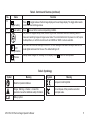
Table 3. Symbology
Symbol
Meaning
Symbol
Meaning
Read the Operator’s Manual.
European Conformity Mark
Danger, Warning, or Caution - Consult the
operators manual for additional safety information.
Do not dispose of this product as unsorted
municipal waste.
Battery symbol
M12 160x120 Thermal Imager Operator's Manual
11
1
2
3
4
5
174.3˚F
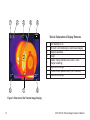
Table 4. Explanation of Display Elements
1
2
3
4
5
98
8
226
7
6
7
8
LED flashlight is on
SD card is not installed (you cannot save images)
Target temperature
Target
Battery charge indicator (more white = more
charge remaining)
Upper limit of range
Picture of color palette in use ("Iron" is shown)
Lower limit of range
6
Figure 5. Elements of the Thermal Image Display
12
M12 160x120 Thermal Imager Operator’s Manual
Battery Life and Power-Saving Features
To preserve battery life, the Thermal Imager goes into
Sleep Mode after 5 minutes of no activity. Sleep Mode
maintains a ready-to-go, warmed-up condition, but uses a
fraction of normal operating battery current. After another
15 minutes of no activity, the Thermal Imager turns itself
completely off. Although you can turn off the Thermal
Imager with the button, you never have to because of its
auto power-off feature.
Using the supplied M12 battery, continuous operating
time is at least 3 hours with the LED flashlight off. If you
are using the Thermal Imager intermittently, Sleep Mode
extends operating time to an entire work day or longer.
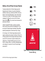
A Fuel Gauge on the Thermal Imager display shows the
capacity remaining in the battery. See Figure 6. When 10%
of charge remains, the Fuel Gauge reads empty and blinks
on and off. This is the time to replace the battery with a
charged one, or charge the battery as soon as you can.
When no charge remains, a Low-Battery Message appears
on the display for 3 seconds. Then the Thermal Imager
shuts itself off.
100%
75%
50%
25%
<10%
LOW BATTERY
Figure 6. Battery Fuel Gauge Levels and Imminent
Shutdown Warning
M12 160x120 Thermal Imager Operator's Manual
13
Taking a Basic Thermal Picture
Proceed as follows to capture and save a basic image set:
Note
An SD card must be installed for the Thermal
Imager to save images and data. If no SD card is
installed, you will see the error message on the
display: “NO SD CARD.”
1. Press and hold (center button on the directional
keypad) for 2 to 3 seconds until you see activity on the
display.
2. The Thermal Imager displays progress messages
about Sensor Calibration during warm-up. From Sleep
Mode, warm-up is almost instantaneous. Until warm-up
is complete, button presses are ignored.
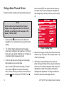
3. If the time and date are not already set, the Settings
Menu appears so you can set these.
Figure 7 shows TIME selected for setting. To set the
button to open the time setting
time, press the
menu. Use the arrow keys to set the current time, then
press the
button to return to SETTINGS. Press
14
twice to select DATE, then set the date the same way
you set the time. Once any settings are changed, the
new settings stay in memory when the power is turned
off.
SETTINGS
EMISSIVITY
0.95
10:45PM
TIME
12 HR
TIME FORMAT
09/29/2011
DATE
MM/DD/YYYY
DATE FORMAT
˚F
SCALE
BRIGHTNESS
ENGLISH
LANGUAGE
ERASE SD MEMORY CARD
Figure 7. Setting Time
4. Open the lens cap by pinching the buttons on the sides
of the lens cap. Flip it open until it snaps in place on top
of the Thermal Imager.
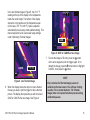
5. Observe the live thermal image on the display as
shown in Figure 8. Rotate the focus ring on the thermal
sensor lens for maximum sharpness. Make small focus
adjustments and wait for the image to settle before
making another adjustment. Focusing has a different
feel than it does with visual image cameras.
M12 160x120 Thermal Imager Operator’s Manual
In the live thermal image in Figure 8, the 411.3 °F
reading at the top of the display is the temperature
inside the center target. The bottom of the display
shows the color palette over the temperature span
(in this case, 370 °F to 446 °F). Span is adjusted
automatically in auto-range mode (default setting). This
manual explains how to use manual range settings
under “Optimizing Thermal Images.”
120.6˚F
CANCEL
230
Figure 9. SAVE or CANCEL a New Image
AUTO
86
SAVE
95
LOW BATTERY
LOW BATTERY
138.9˚F
MANUAL
122
Figure 8. Live Thermal Image
6. When the display shows the object or scene framed
the way you want it, pull the trigger to take a thermal
picture. The display then presents you with choices to
SAVE or CANCEL the new image. See Figure 9.
M12 160x120 Thermal Imager Operator's Manual
button
7. To write the image to SD card, press the
on the arrow keypad or pull the trigger again. Or, to
discard the image, press the arrow button to highlight
button.
CANCEL, then press the
NOTE
Every minute, the Thermal Imager pauses to
calibrate its thermal sensor. You will hear clicking
sounds. This is normal behavior. The Thermal
Imager does not respond to button presses during
calibration pauses.
15
Using the Built-In Visual Image Camera
Every time you take a thermal picture, the Thermal Imager
captures a visual image at the same time. When you save
a thermal image, the Thermal Imager saves the visual
image that goes with it as well. Just like with thermal
images, you can see live visual images on the display.
button to switch between thermal and visual
Press the
images.
Figure 10 shows a visual image as it would appear on
the display. This is the companion to the thermal image in
Figure 8. There is no temperature data associated with a
visual image. Visual images are to help you identify objects
in thermal images.
Figure 10. Live Visual Camera View
Press
again to return to the thermal image view.
The visual image camera has its own lens. It is fixed-focus.
(No focus adjustment is necessary.) The visual image
camera lens is a small rectangular window below the lens,
forward of and above the trigger.
NOTE
If visual images ever seem to have poor quality,
check to see if this lens is dirty. Clean it gently
with a camera lens tissue moistened with camera
lens cleaner fluid.
16
M12 160x120 Thermal Imager Operator’s Manual
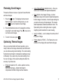
Reviewing Saved Images
•
Proceed as follows to review or “play back” saved thermal
and visual images:
Auto or Manual Range (default is Auto) – Gives you
control over the lowest and highest temperature.
•
Span (default is the Imager’s Range, or widest
temperature range from lowest to highest temperature
that the Imager can detect). A custom span setting lets
you narrow the range of temperatures. This reveals
small temperature variations as different colors. The
Span setting is like reducing the scale in a graph,
magnifying small variations for easier viewing.
•
Level (no default) – Level is always the center point of
the Span or Range.
•
Palette (default is “IRON”) – The Palette is the color
scheme for the display and saved thermal images.
1. Press the
button. This displays the most recent
thermal image. At any time during review, you can
to see its companion visual image.
press
2. Press
(directional arrow on the keypad) to continue
reviewing the next older image. Press to move to the
next more recent images.
3. To return to live view, press
.
Optimizing Thermal Images
Once you become familiar with basic operation, you’re
ready to discover the image enhancement and refinement
you can achieve using custom settings. The custom setting
that has the most impact on temperature reading accuracy
is Emissivity. If you select only one custom setting, this is
the one to change. All the custom settings that affect the
accuracy of your data are:
•
Emissivity (default is 0.95 - rubber, asphalt, concrete,
black electrical tape) – Adjusts the Imager to
compensate for different target surface materials.
M12 160x120 Thermal Imager Operator's Manual
17
Emissivity
Press , select SETUP, then press to get the Setup
Menu as shown in Figure 7. Press and as necessary
to select “EMISSIVITY.” This brings up the Emissivity Menu
as shown in Figure 11.
EMISSIVITY
0.95 DEFAULT
0.30 CUSTOM
MATERIAL
0.30 ALUMINUM
Figure 11. Emissivity Menu
This setting tells the Thermal Imager what surface
material it is measuring. This is important, because
setting the right emissivity has a significant effect on the
accuracy of temperature readings. See Table 5 for a list
of the materials in the Thermal Imager Emissivity menu,
and their corresponding emissivity ratios. You can also
select “CUSTOM” in the emissivity menu, and select any
emissivity value. In Figure 11, “CUSTOM” shows “0.30,” but
when you select CUSTOM, you can choose any value.
18
Emissivity is the ratio of a target surface’s infrared output
(radiance) to that of a blackbody at the same temperature.
A “blackbody” is a theoretical perfect radiator of infrared
radiation (IR).
What this means is you can set the sensitivity of the
Thermal Imager to determine the true temperature of an
object, no matter what its IR radiation characteristics are.
The poorest radiators (surfaces with the lowest emissivity
ratios) need the most correction. These materials are things
like shiny metal and glass.
When you have a low-emissivity surface that you need
a very accurate temperature reading from, placing black
electrical tape or even painting it with flat-black paint is
very effective. Black electrical tape and flat-black painted
surfaces have an emissivity ratio of 0.95.
WARNING
To minimize the risk of electric shock, burn or
fire, never apply electrical tape or paint to an
electrically live surface. Always check to ensure
the power has been turned off before touching a
surface.
M12 160x120 Thermal Imager Operator’s Manual
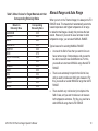
Table 5. Menu Choices for Target Materials and their
Corresponding Emissivity Ratios
Material in
Emissivity Menu
ALUMINUM
ASPHALT
BRICK
CONCRETE
COPPER
IRON
OIL (PETROLEUM)
PAINT
RUBBER
SAND
SOIL
STEEL
WATER
WOOD
Corresponding
Emissivity Ratio
0.30
0.95
0.83
0.95
0.60
0.70
0.94
0.93
0.95
0.90
0.92
0.80
0.93
0.94
M12 160x120 Thermal Imager Operator's Manual
Manual Range and Auto Range
When you turn on the Thermal Imager, it is always in AUTO
RANGE mode. This means that it automatically selects the
lowest temperature and highest temperature in its range
to make thermal images. Usually, this produces the best
results. However, if you want to use a narrower or wider
temperature range, you can select MANUAL RANGE.
Typical reasons for selecting MANUAL RANGE:
•
An area in the field of view that you want to focus on
has a narrow range of temperatures, and you want to
be able to resolve these small differences. For this,
you would set a narrower MANUAL range than AUTO
RANGE.
•
There is one extremely hot point in the field of view,
and you want to make sure that it gets measured. For
this, you would set a wider MANUAL range than AUTO
RANGE.
•
There are both very cold and very hot objects in the
field of view, and you want to make sure to measure
both temperature extremes. For this, you would set a
wider MANUAL range than AUTO RANGE.
19
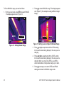
To Set a MANUAL range, proceed as follows:
1. From live view mode, press
then select RANGE.
.The display appears as in Figure 12:
2. Press
to select MANUAL range. The display appears
as in Figure 13 (this example is using a different target
image):
66.2˚F
120.6˚F
AUTO
86
MANUAL
122
Figure 12. Setting Manual Range
LEVEL
50
SPAN
70
Figure 13. Setting Level and Span for Manual Range
3. Press and to experiment with the SPAN setting
to choose the best looking display for the area you are
studying.
4. Press and to experiment with the LEVEL setting
to choose the best looking display for the area you are
studying. When you move the LEVEL, you shift the
whole fixed window of temperature range up or down.
to accept your custom LEVEL and SPAN
5. Press
settings and remain in MANUAL range mode.
20
M12 160x120 Thermal Imager Operator’s Manual
Changing the Color Palette
The default color palette is called “IRON.” IRON, RAINBOW and GREY are all shown in Figure 14. IRON is the default. It
is better at revealing small temperature differences.
99.0˚F
IRON
71
RAINBOW
110.0˚F
GRAY
111
IRON
RAINBOW
69
101.2˚F
GRAY
111
IRON
RAINBOW
71
GRAY
111
Figure 14. IRON, RAINBOW and GRAY Color Palette Choices
You can change to two other color palettes: “RAINBOW”
and “GRAY.” GRAY shows the most detail and is useful for
record keeping or reporting in formats that do not allow the
use of color. RAINBOW is an alternative to IRON, which
uses more colors. RAINBOW is better for show a very wide
range of temperatures because of the additional colors. To
change the color palette, proceed as follows:
M12 160x120 Thermal Imager Operator's Manual
1. From the live view mode, press
then if needed
to select COLOR, then . This opens the menu bar
shown in Figure 14. Press the and arrow buttons to
to confirm it.
make your selection, then press
21
Changing the Settings
Use the SETUP menu to set the TIME, TIME FORMAT,
DATE, DATE FORMAT, SCALE (˚F or ˚C), BRIGHTNESS,
LANGUAGE, and the way to erase images on the installed
SD memory card. To call up the SETTINGS menu, from
, then
if needed to select SETTINGS,
live mode press
to confirm your selection. The SETTINGS menu is
then
shown in Figure 15.
1 Press and to select the menu item to set, followed
t to confirm your slection.
by
2. Press and to change the setting, followed by
to confirm the change. Changes you make to settings
remain in effect even after you turn off the power and
turn it back on again.
SETTINGS
EMISSIVITY
0.95
10:45PM
TIME
12 HR
TIME FORMAT
09/29/2011
DATE
MM/DD/YYYY
DATE FORMAT
˚F
SCALE
BRIGHTNESS
ENGLISH
LANGUAGE
ERASE SD MEMORY CARD
Figure 15. The Settings Menu
22
M12 160x120 Thermal Imager Operator’s Manual
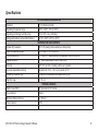
Specifications
Drop test
PHYSICAL AND ENVIRONMENTAL
3’ (1m) drop to concrete
Operating temperature range
Operating and storage humidity range
Storage temperature range without battery1
Infrared (IR) resolution
14°F to 122°F (-10°C to +50°C)
10% to 90%, non-condensing
-13°F to 140°F (-25°C to +60°C)
TEMPERATURE MEASUREMENT
160 X 120 pixels (picture elements, or data points)
Object temperature range2
Thermal sensitivity
Spatial resolution
14°F to 662°F (-10°C to 350°C)
0.1°C per 30°C Noise Equivalent Temperature Difference (NETD)
2.7 mrad Instantaneous Field of View (IFOV)
Accuracy
±4°F (2°C) or ±2% or reading, whichever is greater
On-board adjustable emissivity
Variable from 0.01 to 1.00, in increments of 0.01
Infrared (IR) detector type
Uncooled microbolometer focal-plane array (FPA)
Spectral range
8 to 14 μm
Field of view (FOV)
THERMAL IMAGING
25° Horizontal X 19° Vertical
Focus method
Manual
Minimum distance in focus
Screen refresh
3.9”.(10 cm)
60 Hz
M12 160x120 Thermal Imager Operator's Manual
23
VISUAL IMAGING
Visual digital camera resolution
1.3 Megapixels
Field of View
56º Horizontal X 46º Vertical
Minimum distance in focus
11.8 in. (30 cm)
Focus method
Fixed
Exposure control
Auto
LED flashlight3
User-selectable on or off
Battery system
Image storage system
Data communication interface
GENERAL
MILWAUKEE M12 Series rechargeable Li-Ion removable battery and M12 Series
drop-in battery charger
Removable 2 GB SD card installed, room for >300 image sets. The Thermal
Imager is tested to accommodate up to 32GB SD card (>4,800 image sets).
Mini USB with rubber flap called the media door to seal out dust and water
Display
Color TFT-LCD 3.5 in. (9 cm) measured diagonally
Note 1: For the M12 rechargeable battery temperature and humidity ranges, refer to its Operator’s Manual
Note 2: The Thermal Imager displays readings <10°C and >350°C, but these readings are not specified
Note 3: THe LED floodlight does not affect thermal images
24
M12 160x120 Thermal Imager Operator’s Manual
Glossary
Term
Definition
160x120
The number of pixels (picture elements or dots) in a saved thermal image. Each pixel has a
temperature associated with it. Each thermal image is 160 pixels wide by 120 pixels high.
accuracy
The guaranteed correctness of a temperature reading. For example, ± (2° or 2% of reading),
whichever is greater.
ambient temperature
The surrounding background or environmental temperature around the Thermal Imager.
blackbody
A blackbody absorbs all thermal radiation striking it and emits all of it back. This means that a
perfect blackbody has an emissivity of exactly 1. Surfaces that are closest to a blackbody in
real world applications are flat black paint and black electrical tape. (See “emissivity.”)
battery fuel gauge
A symbol on the display in the shape of a battery, with a bargraph indicating the level of
remaining charge. The more white bars showing, the more charge remaining.
brightness level
Refers to the display brightness, which you can adjust in the Setup Menu.
calibrate, calibration
Comparing a measurement device’s readings to a reference standard. Calibration usually
involves adjustment to correct for errors, but not always. In the Thermal Imager, an internal
reference standard calibrates the unit once per minute. Also see “Calibration interval.”
calibration interval
The period of time after production or re-calibration that a measurement device’s
specifications are valid --1 year for the Thermal Imager. After 1 year, contact a MILWAUKEE
Service Center for factory calibration to renew the calibration cycle.
camera
Refers to the built-in visual image digital camera.
camera lens
Refers to the front optical element in the built-in visual digital image camera, located between
the flashlight LEDs below the Thermal Imager lens. This is a fixed-focus lens – no adjustment
required.
M12 160x120 Thermal Imager Operator's Manual
25
CD
Compact Disk. Also called a CD ROM, for CD Read-Only Memory. The CD supplied with the
Thermal Imager contains software and manuals.
Celsius
A temperature scale based on 0 °C as the freezing point of water and 100 °C as the boiling
point of water at a reference barometric pressure.
color palette, palette
A thermal image color scheme. Generally, black is the coldest and white is the hottest, but you
can choose the colors that represent the intermediate temperatures in the scale. Palette is one
of the Setup menu choices in the Thermal Imager: IRON, RAINBOW and GRAY.
detector
Also called “sensor,” the component that detects infrared radiation to determine temperatures.
The Thermal Imager’s detector is a microbolometer. (See “microbolometer” and “FPA.”)
detector, Infrared
A transducer element that converts incoming radiant infrared energy striking its surface into an
electrical signal.
directional keypad
The round group of arrow keys and center function key on the keypad.
display
The screen on the Thermal Imager that presents thermal or visual images and operating menu
choices.
emissivity (ε)
The ratio of infrared emitted by an object divided by infrared emitted from a blackbody at the
same temperature. The Thermal Imager allows you to select from a list of surface materials
to maximize accuracy of the temperature readings. This is called “adjustable emissivity.” (See
also “blackbody.”)
Fahrenheit
A temperature scale based on 32 °C as the freezing point of water and 212 °C as the boiling
point of water at a reference barometric pressure.
field of view (FOV)
Stated in angular degrees, the width and height of the area that the Thermal Imager senses all
incoming infrared energy to produce a thermal image.
26
M12 160x120 Thermal Imager Operator’s Manual
fixed focus
An optical system for a camera or thermal imager that is set to one average distance, resulting
in an in-focus range that is not adjustable.
FPA (focal-plane
array)
A rectangular flat-panel matrix of detector elements on which the Thermal Imager’s optical
lenses and filters focus infrared energy to produce a thermal image. The type of FPA used in
the Thermal Imager is called a microbolometer. It produces signals that make a new complete
thermal image 60 times per second.
focal point
The distance from the lens at which the thermal imager is in focus.
focus distance
The closest distance at which you can focus the thermal image: 11.8 inches or 30 cm.
focusing ring
The movable ring around the front lens that you adjust for the sharpest thermal image. This
has no effect on the visual digital camera image.
frame rate
The number of times per second that the Thermal Imager displays a completely updated
thermal image: 60 times per second, or 60 Hz (Hertz).
full scale
The minimum temperature and the maximum temperature that the Thermal Imager can
measure. When in AUTO RANGE mode, the Thermal Imager adjusts itself to a portion of full
scale, called “span” that is somewhere within the full-scale endpoints. Using MANUAL RANGE
settings, you can set the Thermal Imager to cover full scale, but usually this makes it more
difficult to discern small temperature variations in the thermal image.
function key
The
button on the directional keypad. Its function changes depending on what activity is
happening. It is often used as the ENTER key to confirm a menu selection.
image
Either a thermal image or a visual image. The Thermal Imager captures both kinds every time
you pull the trigger. The pair of images are called an “image set.” When you save, erase, or
load an image to a PC, both the thermal and visual images always stay bundled together.
M12 160x120 Thermal Imager Operator's Manual
27
infrared (IR)
Electromagnetic energy in wavelengths that are between visible light and RF (radio
frequency).
infrared detector
A transducer element (sensor) that converts incoming radiant infrared energy striking its
surface into an electrical signal. The Thermal Imager measures this signal and translates it
into a thermal image (Also see “bolometer.”)
IP rating
An international standard rating system for a device’s resistance to water and dust
JPEG (.jpg)
A file format used for digital photographs.
LCD
Liquid-Crystal Display -- the type of color display on the Thermal Imager.
LED
Light-Emitting Diode – used as light-up indicators
LED floodlight
A floodlight to illuminate the work area. It helps with the visual images, but does not change
thermal images.
lens cap
A protective cover over the thermal imager lens.
level
The mid-way temperature point of the range in use. When you adjust the level, the width of the
window from lowest to highest temperature stays the same and the whole window moves up
or down in temperature.
Li-Ion
Lithium-Ion: the type of rechargeable battery used in the MILWAUKEE M12 series products.
load
The term for transferring images to a computer. You can load images directly from the SD card
using the SD card reader USB adapter, or from the Thermal Imager with the SD card installed,
using the USB cable.
M12
A family of MILWAUKEE 12V Li-Ion rechargeable battery powered tools, rechargeable
batteries and accessories.
media door
The rubber cover over the SD card slot and Mini USB socket on the side of the Thermal
Imager.
28
M12 160x120 Thermal Imager Operator’s Manual
menu
On the Thermal Imager, a menu is a list of choices you can make for settings, such as time,
date, color palette, span and emissivity.
microbolometer
The type of thermal infrared detector used in the Thermal Imager. It is an array of 160 by 120
thermal sensors that respond to infrared radiation (IR).
MILWAUKEE
Short for Milwaukee Electric Tool Corp., www.milwaukeetool.com. The mailing address for the
company headquarters is 13135 W. Lisbon Rd., Brookfield, WI 53005, USA.
mini USB
The small USB data socket on the Thermal Imager and small USB plug on the USB interface
cable. USB stands for Universal Serial Bus.
object temperature
range
Same as temperature range: the lowest measurable temperature to the highest measurable
temperature of a temperature measuring device such as the Thermal Imager.
operating
temperature
The lowest ambient temperature to the highest ambient temperature in which you can operate
the Thermal Imager.
palette
A thermal image color scheme. Generally, black is the coldest and white is the hottest, but you
can choose the colors that represent the intermediate temperatures in the scale. Palette is one
of the Setup menu choices in the Thermal Imager: IRON, RAINBOW and GRAY.
pixel
Picture element. One “dot” on the display or in a digital image. Many pixels are used to form
an image.
precision
In a measurement device, precision is how close tightly grouped readings are. Accuracy
combines precision and how close the reading is to a perfect measuring device or a calibration
laboratory standard.
radiation, thermal
Infrared emission from a target area. Thermal radiation intensity drops off predictably with
distance.
range
The lowest measureable temperature to the highest measureable temperature.
M12 160x120 Thermal Imager Operator's Manual
29
resolution
Same as “thermal sensitivity.” The number of meaningful digits in a temperature reading, for
example, “10 °C, 10.1 °C, or 10.01 °C.” For the 10.01 °C reading, the resolution is “0.01 °C.”
saved image
An image written (recorded) onto the SD card installed in the Thermal Imager. Once saved,
images stay intact on the SD memory card when you turn off the Thermal Imager power.
scale
The Thermal Imager uses your choice of two temperature scales: °C for Celsius or °F for
Fahrenheit.
SD Card
Removable, reusable flash memory storage cards commonly used in digital cameras. The
Thermal Imager accepts SD (up to 4 MB) and SDHC (for “High Capacity,” greater than 4 MB
up to 32 MB) SD cards. It does not accept mini-SD or micro-SD cards.
sensor
Also called “detector,” or “thermal sensor,” the component that detects temperatures
throughout the field of view. Model M12 160x120’s detector is a microbolometer. (See
“microbolometer.”)
sleep mode
Automatic battery-conserving mode that begins after 5 minutes with no activity. The Thermal
Imager remains ready to operate, so warm-up is not required when in sleep mode. This is not
the same as auto power-off, which occurs after 20 minutes of no activity.
span
The width of the measurement window from the lowest measured temperature to the highest
measured temperature. The “Level” setting moves this window up or down in temperature.
spectral range
The IR bandwidth, or longest to shortest infrared wavelengths that the Thermal Imager
detects.
storage
Electronic memory (also called “Flash memory”) for saving the images and data created in
the Thermal Imager during a work session. The Thermal Imager uses a standard SD (Secure
Digital) removable, re-usable memory card as its sole storage system. Once images are
loaded onto a computer, you can erase the SD card.
30
M12 160x120 Thermal Imager Operator’s Manual
storage temperature
The lowest ambient temperature to the highest ambient temperature in which you can store
the Thermal Imager while it is not being used.
target
The area in a thermal image in the center, defined by square corner markers on the display,
whose temperature is displayed in 0.1 degree resolution at the top of the display. The
temperature is the average of all the pixels contained within the brackets.
Thermal Imager
Shorthand name for the M12 160x120 Thermal Imager.
thermal imager lens
The main lens on the Thermal Imager that has the hinged lens cap. This lens focuses infrared
radiation (IR) on the thermal sensor. There is another, smaller lens for taking visual digital
images.
thermal mass
Objects with low thermal mass revert to ambient temperature more quickly than objects with
low thermal mass. For example, a cast-iron engine block has higher thermal mass than an
aluminum one. Thermal mass and mass are not the same thing.
thermal radiation
Infrared emission from a target area. Thermal radiation intensity infrared radiation drops off
predictably with distance. This is why fixed-focus thermal imagers are less accurate than ones
you focus. Focusing tells the Thermal Imager how far away the target is, so the imager can do
the math to calculate the readings accordingly.
thermal sensitivity
The smallest increment of temperature measurement resolved by the digital reading.
Equivalent to temperature resolution. (10 °C vs. 1 °C vs. 0.1 °C.)
thermal sensor
Also called “detector,” or “sensor,” the component that detects temperatures throughout the
field of view. The Thermal Imager’s detector is an uncooled microbolometer.
thermographic study
Taking thermal images and interpreting them to check for problems, or to create a periodic
record of temperatures for maintenance records.
M12 160x120 Thermal Imager Operator's Manual
31
toggle
button to switch between thermal visual image display and visual image
Press the
display. the display This works in live mode as well as in image review mode.
trigger
The finger-lever at the top of the hand grip that you to take a thermal image. Pull it once to
take the image and pull it again to save it to the SD card. (You have the choice after the first
pull to save or choose CANCEL to discard the image.)
Type A USB
The larger, flat USB data socket on a computer and larger flat plug on the Thermal Imager’s
USB interface cable.
USB
Universal Serial Bus. The most common computer interface for connecting cameras, external
disk drives and pocket-sized thumb drives.
visual image
A digital photograph that is saved with each thermal image, that provides visual context for
what is in the thermal image.
32
M12 160x120 Thermal Imager Operator’s Manual
M12 160x120 Thermal Imager Operator's Manual
33
USA - MILWAUKEE Service
Canada - Service MILWAUKEE
MILWAUKEE prides itself in producing a premium quality product that is
Nothing But Heavy Duty®. Your satisfaction with our products is very important to us! If you
encounter any problems with the operation of this tool, or you would like to locate the factory
Service/Sales Support Branch or authorized service station nearest you, please call:
1-800-SAWDUST (1-800-729-3878)
1-800-268-4015 Monday-Friday 7:00 AM – 6:30 PM Central
Monday-Friday 7:00 AM – 6:30 PM Central
or visit the MILWAUKEE website at www.milwaukeetool.com
In addition, authorized distributors are ready to assist you with your tool and accessory
needs. Check your local business-pages phone directory under "Tools-Electric" for the
names and adresses of distributors nearest you, or see the "Where to Buy" section of www.
milwaukeetool.com.
For Service Information, click on "Service Center Search" in the "Parts & Service" section of
the MILWAUKEE website. For technical support or questions about service, repair or
Warranty, contact MILWAUKEE Corporate After Sales Service Technical Support in any
of these ways:
call: 1-800-SAWDUST(1-800-729-3878), FAX: 1-800-638-9582
or email: [email protected]
Register your tool online at www.milwaukeetool.com and...
•receive important notifications regarding your purchase
•ensure that your tool is protected under the Warranty
•become a Heavy Duty club member
FAX: 1-866-285-9049, or visit the MILWAUKEE website at
www.milwaukeetool.com
In addition, authorized distributors are ready to assist you with your tool and accessory needs.
Call the numbers above or see the "Where to Buy" section of www.milwaukeetool.com.
Milwaukee Electric Tool (Canada) Ltd.
140 Fernstaff Court, Unit 4
Vaughan, ON L4K 3L87
18129 111th Ave NW
Edmonton, AB T5S 2P2
MILWAUKEE est fi er de proposer un produit de première qualité
Nothing But Heavy Duty®. Votre satisfaction est ce qui compte le plus! En cas de problèmes
d’utilisation de l’outil ou pour localiser le centre de service/ventes ou le centre d’entretien le
plus proche, appelez le : 1-800-268-4015 Lundi – Vendredi 7:00 – 4:30 Central.
FAX : 866-285-9049. Notre réseau national de distributeurs agréés se tient à votre
disposition pour fournir l’aide technique, l’outillage et les accessoires nécessaires.
Composez le 1-800-268-4015 pour obtenir les noms et adresses des revendeurs les plus
proches ou bien consultez la site web à l’adresse www.milwaukeetool.com
MEXICO - Soporte de Servicio MILWAUKEE
CENTRO DE ATENCIÓN A CLIENTES
Rafael Buelna No. 1, Col Tezozomoc, Delegación Azcapotzalco, México, D.F.
Telefono sin costo 01 800 832 1949, e-mail: [email protected]
Adicionalmente, tenemos una red nacional de distribuidores autorizados listos para
ayudarle con su herramienta y sus accesorios. Por favor, llame al 01 800 832 1949 para
obtener los nombres y direcciones de los más cercanos a usted.
58-14-2260
O consulte la sección <<Where to buy>> (Dónde comprar) de nuestro sitio web en:
www.ttigroupmexico.com
Registre su herramienta en línea, en www.ttigroupmexico.com y...
• reciba importantes avisos sobre su compra
• asegúrese de que su herramienta esté protegida por la garantía
• conviértase en integrante de Heavy Duty
MILWAUKEE ELECTRIC TOOL CORPORATION
13135 West Lisbon Road • Brookfield, Wisconsin, USA 53005
11/11