1
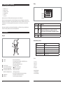
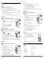
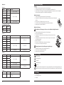
LCR-Messgerät UNI-T UT603 Best.Nr. 830 506 Auf unserer Website www.pollin.de steht für Sie immer die aktuellste Version der Anleitung zum Download zur Verfügung. ® Sicherheitshinweise • Diese Bedienungsanleitung ist Bestandteil des Produktes. Sie enthält wichtige Hinweise zur Inbetriebnahme und Bedienung! Achten Sie hierauf, auch wenn Sie das Produkt an Dritte weitergeben! Bewahren Sie deshalb diese Bedienungsanleitung zum Nachlesen auf! • Benutzen Sie das LCR-Messgerät nicht weiter, wenn es beschädigt ist. • Vergewissern Sie sich, dass die Messklemmen in einwandfreiem Zustand sind. Führen Sie auf keinen Fall Messungen durch, wenn die schützende Isolierung beschädigt ist. • Um einen elektrischen Schlag zu vermeiden, achten Sie darauf, dass Sie die zu messenden Anschlüsse / Messpunkte während der Messung nicht, auch nicht indirekt, berühren. • In Schulen, Ausbildungseinrichtungen, Hobby- und Selbsthilfewerkstätten ist das Betreiben durch geschultes Personal verantwortlich zu überwachen. • In gewerblichen Einrichtungen sind die Unfallverhütungsvorschriften des Verbandes der gewerblichen Berufsgenossenschaften für elektrische Anlagen und Betriebsmittel zu beachten. • Das Produkt darf nicht fallen gelassen oder starkem mechanischem Druck ausgesetzt werden, da es durch die Auswirkungen beschädigt werden kann. • Das Gerät muss vor Feuchtigkeit, Spritzwasser und Hitzeeinwirkung geschützt werden. • Betreiben Sie das Gerät nicht in einer Umgebung, in welcher brennbare Gase, Dämpfe oder Staub sind. • Dieses Gerät ist nicht dafür bestimmt, durch Personen (einschließlich Kinder) mit eingeschränkten physischen, sensorischen oder geistigen Fähigkeiten oder mangels Erfahrung und/oder mangels Wissen benutzt zu werden, es sei denn, sie werden durch eine für ihre Sicherheit zuständige Person beaufsichtigt oder erhielten von ihr Anweisungen, wie das Gerät zu benutzen ist. • Das Produkt ist kein Spielzeug! Halten Sie das Gerät von Kindern fern. ! Pollin Electronic GmbH • Max-Pollin-Str.1 • 85104 Pförring • Tel. (08403) 920-920 • www.pollin.de Stand 22.04.2013, rut (UT603 measurement mode. damaged insulation or Model UT602/603: OPERATING MANUAL only) Press L-C up to enter the Inductance measurement exposed metal. Check the test clips for continuity. the proper terminals, function, and range for Use The rotary switch should be test placed rightmodel Replace damaged clips in withthe identical mode. Display Bestimmungsgemäße Verwendung or electrical specifications your measurements. position and no number any changeover of range before shall using be the Display Symbols (see Das Digitale Messgerät eignet sich für folgende Messungen: Button Description Meter. made during measurement is conducted to prevent environment of Meter in an • Induktivität 0...20 H Do not use or store not apply voltage to the Meter. to turn Do the Press the Power down the Meter on. clips for Inspect Do not applytovoltage tothe thetest Meter. and damage the Meter. War To avoi test, di figure 2) high-vo Power continu a damage of the Meter. • Kapazität 0...600 µF high temperature, humidity, explosive, inflammable No. Symbol Meaning rotary switch should be placed in the right The • Widerstand 0...20 MΩ Do not Press the again to of turn Meter magnetic field. The performance ofthe the Do strong not apply more than 30Vrms between the and position and noPower any changeover range shall bepower off. ock or injury, • personal Durchgangsprüfung The battery is low. 1 to avoi b (figure 2) • Meter Dioden-Testor to the Mterminals e t e r m aand yHold d emade tgrounding ePress r iduring o r aHOLD t emeasurement a once favoid t e r todis aconducted m pthe en etod prevent .feature, the LCD the to electric shock enter hold e to the (figure 1) damage of the Meter. c • Transistor-Test Warning: To avoid false readings, Wa and damage to thepower Meter. and. discharge all highModel UT90C: OPERATING MANUAL e to the following rules: circuit Disconnect Testing not apply moreIII.than 30Vrms between the Do display d Das Gerät wird mit einer 9 V- Blockbatterie betrieben(UT602 und entspricht somit der Schutzklasse which could lead to possible electric shock (figure 2) terminals and function, the grounding to avoid electric Use thecapacitors proper terminals, and range forshock voltage To avo before testing resistance, Rotary Switch 1) ct the case. not use Press HOLD again to exit hold feature, the Model UT90C: (figure OPERATING MANUAL only) Eine andereDo Verwendung als angegeben ist nicht zulässig! Änderungen können zur Beschädigung dieses Produktes führen, Warning Use the d and damage to the Meter. or personal injury, Symbols replace the(see battery as 2) test, d your continuity, capacitance or diodes. darüber hinaus ist dies Gefahren, wiemeasurements. z.B. Kurzschluss, Brand, elektrischem Schlag etc. verbunden. Für alle Personen- und Display figure the case (or part ofmitthe Below table indicated for information about the rotary semicon disappear. the ist proper function, and range for Use the Me (figure 3) To avoid damages tohigh-v Rotary Switch Sachschäden, die aus nicht bestimmungsgemäßer Verwendung entstehen, nicht derterminals, Hersteller, sondern der Betreiber switch positions. as the battery indicator appears.test, disconnect through acks or missing plastic. Nummer Symbol soon Bedeutung environment Do not the usebattery or store Meter in an asthe soon as the battery indicatorof Replace circuit pow your measurements. verantwortlich. Display Symbols (see figure 2) Press L-C down to enter the Capacitancea L-C humidity, contin Below indicated for information about the rotary Rotary high-voltage capacitors befo around the connectors.high Transistor-Test temperature, explosive, inflammable appears. With low the Meter might Meaning No. Symbol Function of usebattery, or store the Meter in an environment Doanot β table Transistor Test the voltag 2 switch positions. Switch Bitte beachten Sie, dass Bedien- und/oder Anschlussfehler außerhalb unseres Einflussbereiches liegen. Verständlicherweise continuity. Do not Position Meaning measurement mode. high temperature, humidity, explosive, inflammable No. Symbol (UT603 andentstehen, strong magnetic field.can The performance of the produce false readings that lead to electric shock können wir für Schäden, dieor daraus keinerlei Haftung übernehmen. drops amaged insulation b Die is Batterie istoff. schwach Model UT90C:Rotary OPERATING MANUAL Do not input more than be DC OFF Power turned The battery is low. Test of diode. 1 3 and strong magnetic field. The performance of the to avo Function Model UT90C: OPERATING MANUAL battery is low. Switch The Achtung: Um falsche Messwerte zu vermeiden, sollten Sie die M e t e r m a y d e t e r i o r a t e a f t e r d a m p e n e d . and personal injury. 1 AC/DC voltage measurement. Press L-C up to enter the Inductance measurement to avoid electric shock an only)M e t e r m a y d e t e r i o r a t e a f t e r d a m p e n e d . est clips for continuity. To test a Position sobald das dem Display erscheint! Warning: To avoid false readings, continuity isSymbol on. auf Switch The :Batterien Diode test.wechseln, 4 RotaryOFF Warning: To avoidbuzzer false readings, Bedienelemente Power is turned off. with identical model test clips from the Meter and turn the Remove Disconnect circuit power and discharge allMeter highmode. circuit power and discharge all high Disconnect Testing Testing Diodes n safety and :Durchgangsprüfung Continuity test. cRotary Switch which AC/DC voltage measurement. could lead to possible electric shock 1. Insert Below table indicated for information about the to rotary which could lead possible electric shock voltage capacitors before testing resistance, ations before using the power off before opening the Meter case. voltage capacitors before testing resistance, :Diodentest test. the rotary :Capacitance Diode test. about on carefully switch positions. Measurement Operation Use the diode test to check dio dBelow table indicated for information Messgerät or personal injury, replace the battery as Use the the bla continuity, capacitance or diodes. switch positions. Ω or Ω Continuity test. personal injury, replace the battery as semiconductor devices. The d : Resistance measurement. When servicing the Meter, use only the same model continuity, capacitance or diodes. es strictly. RotaryHz soon as the battery indicator appears. semicon Replace the battery as soon as the battery indicator Frequency Test. Function Low Battery Display is notthrough on, the semiconductor Make : Capacitance test. jun Switchsure the 2. Set th Meter. Rotary 1 or identical electrical specifications soon as the battery indicator appears. Function Replace the battery appears. as soon as the battery number With a low battery,indicator the Meter might Transistor Test Drehwahlschalterpositionen the voltage drop across the junc Switch Ω 2PositionβΩ through AC DC Current Measurement may be provided. :orResistance measurement. otherwise false readings OFF Power is turned off. Position replacement produce falsebattery, readings that lead to might electric shock drops between 500mV and for 80 Hz Frequency Test. 3.the be placed in the right For appears.parts. With a low thecan Meter Test of diode. βAC/DC Transistor Test symbol, before carrying 3 extra volta OFF Power is turned off. 2 voltage measurement. Pay attention to the 2 and personal injury. 7 230V MAX: To test a diode out of a circuit, co (figure 4) PositionAC/DC: voltage Funktion ACCharge ortest. DC Current Measurement over of range measurement. The internal circuit of the Meter shalltonot be altered compo Diode produce false readings that can lead electric shock continuity buzzer is on. at 220VAC. 4 ry, read the shallbe drops b CHARGE The measurement, which is located besides the input Test of diode. Remove test clips from the Meter and turn the Meter 3 test. 12-36V : Charge at : Diode Manual covers information on safety and Diodentest/Durchgangstest : Continuity test. sng conducted to prevent 1. Insert the red test clip into th 6 damage at willpersonal to avoid thebefore Meteropening and anythe accident. and injury. 12-36V . Operation" powerofoff Meter case. Operation 230V MAX: Toanode test a ease read the relevant information carefully Measurement terminals of the Meter. : Continuity test. : Capacitance test. The continuity buzzer is on. the black test clip into the CO Charge at 220VAC. 200/2k/20k/200k/2M/20M (Ω) Widerstandsmessung 3 4 CHARGE cathod When servicing the Meter, use only the same model e all the Warnings and Notes strictly. Soft clothtest and mild detergent should be the used to 12-36V :ΩCapacitance test. : Charge at Remove clips from the Meter and turn Meter Ω sure n safety and : Resistance measurement. the Low Battery Display (Stromverstärkungsfaktor) is not on, hMake Model UT90C: OPERATING MANUAL 2. Set the rotary switch 12-36V . Transistor-Test to d number or identical electrical specifications 1.The FE Insert Ω Ω Hz Frequency Test. 30Vrms between the : Resistance measurement. clean the surface of the Meter when servicing. No Model UT90C: OPERATING MANUAL power off before opening the Meter case. A. Measuring Resistance (see figure 3) otherwise false readings may be provided. Measurement Operation gion carefully replacement parts. 600µ/200µ/20µ/2µ/200n/20n/2n 3. For forward voltage drop Hz Frequency Test. (F) Kapazitätsmessung (figure 2) T602/UT603 theread bl neares Switch attention to theMeasurement symbol, before carrying Pay extra AC or DC Current to avoid electric shock abrasive and Rotary solvent should be used to prevent the When servicing the Meter, use only the same model (figure 1) tes strictly. The internal circuit of the Meter shall not be altered component, place the red te 2mH/20mH/200mH/2H/20H (LMeasurement ) Induktivitätsmessung ectric shock or personal injury, read the Rotary AC or DC Warning Current x is located besides the input measurement, which 5 Switch 4 2 digits with sure the Low Battery Display is not anode on, and place the Make Warning 2. Set surface ofor the Meter from damage and at will to avoid damageabout ofspecifications the Meter accident. blackth te Below table indicated forcorrosion, information the rotary and any number identical electrical rmation" and "Rules for Safety Operation" MAX: terminalsof230V the Meter. switch positions. Note ghly reliable Below table indicated for information about the rotary Charge at 220VAC. otherwise readings may be provided. cathode. CHARGE 230V false MAX: fore using the Meter. Soft cloth and mild detergent should be used to accident. unction, and range forreplacement To12-36V avoid damages toor the or to theunder devices under 3. For fo parts. : Charge at switch positions. Charge at 220VAC. ToCHARGE avoid damages to Meter toMeter the devices The display shows the dio Einheiten: 12-36V . the of the Meter when servicing. No A. Measuring Resistance (see figure 3) Rotaryclean the surface Pay extra attention to symbol, before carrying 12-36V : Charge at the Function 1 LC-Display Dient zur Anzeige der Messwerte. a cir test, disconnect circuit power and discharge the Incomp the Meter power off when it is not in use and Turn ance Capacitance Meter Model UT602/UT603 Switch nearestall value. 12-36V . Display Symbols (see figure 2) The internal circuit of the Meter shall not be altered Rotary abrasive and solvent should be used to prevent the test,measurement, disconnect circuit power and discharge all input the ury, read the Function Position 2 L-C-Taste Zum Umschalten zwischen Kapazitätsund Induktivitätsmessung. -3 which is located besides the Switch UT603 m = Milli (10 Warning ) ferred to ascan "the Meter") is a 3take 1/2 digits high-voltage capacitors before measuring diodes and voltage outtowith the battery when not using forcorrosion, a long time. surface ofturned the(C). Meter from damage and OFF Power is off. environment ofat will r Operation" in an Position avoid damage of the Meter and any accident. anode Eingerastet: Kapazitätsmessung capacitors before measuring resistance. yey µ =high-voltage Microterminals (10-6) Note ations, fashionable design and highly reliable OFF of the Meter. both can Power is turned off. accident. continuity. reverse AC/DC voltage measurement. Nicht eingerastet: Induktivitätsmessung (L). -9 explosive, inflammable To (10 avoid Meaning No.mild Symbol n = Nano ) damages to the Meter or to the devices under catho constantly check the battery as it may leak Please easuring instrument. Soft cloth and detergent should voltage measurement. :the Diode test. , 200 2kall60V , the 20kor ,AC 200k The resistance are 20 circuit, a good diode sho In a, voltages 3 Transistor-Testsockel Zum Testen eines Transistors. Turn Meter power off whenbe it isused not in to use and AC/DC inuity buzzer Doranges not input more than,DC 30V resista k = Kilo (103) disconnect test, circuit power and discharge he performance of the : Diode test. The d can measure inductance, while UT603 can when itthe using for some time, replace the voltage drop reading of 500m :the Continuity test. 4 Anschlüsse für Widerstandsmessung, has Ω been -Buchse: Positiver Anschluss. clean surface of Meter when servicing. No 6 take out the battery when not using for a long time. A.,(1020M Measuring Resistance (seeresistance. figuredamage 3) The battery is low. and 2000M . M 2M = Mega ) 1 high-voltage capacitors before to avoid electric shock and toreverse the Meter. Conne 10 measuring : Continuity test. test. pacitance both can Diodentest Durchgangsprüfung COM-Buchse: Negativer Anschluss. UT602/UT603 voltage drop reading a f t e r and d ainductance. m pund en e dThey . : Capacitance neare battery as and soonsolvent as leaking appears. A the leaking battery constantly check battery as itthe may leak Please abrasive should beWarning: used toTo prevent , 2k connect , 20k , 200kthe , Meter resistance The resistance resistance, ranges are 20 , 200 measure please as :ΩCapacitance stance, 5 transistor, diode andund continuity avoid false readings, ΩTo Anschlussbuchsen Messsockelbuzzer für +-Buchse: Anschluss. test. of other above pathway Ω Positiver = Ohm (Widerstand) : Resistance measurement. 1/2 digits with when it has been using for some time, replace the will damage the Meter. , 20M and 2000M . 2M Warning nd discharge all highsurface of the Meter from corrosion, damage and 10 Induktivitätsund Kapazitätsmessung --Buchse: Negativer Anschluss. Testing Diodes Ω Ω Connect the test clips to the Hz Frequency measurement. Test. follows: : Resistance an extra Data Hold feature. F = Farad (Kapazität) indicat battery asAnschluss soon as leaking appears. leaking battery which could lead toApossible electric shock To measure resistance, please connect the Meter as Note highly reliable Messsockel: Ein direkter für Spule oder Kondensator. Hz Frequency Test. above to avoid error display testing resistance, H = Henry (Induktivität) accident. or DC Current Measurement willAC damage the Meter. g Inspection 1. follows: Insert redthe testdiode clipthe into thecheck terminal and diode 6 Drehwahlschalter Zum Electrical Umschalten der Messfunktionen (Siehe S.3). avoidthe damages to Meter or todiodes, the devices under Use test to transistors, and other International Symbols indicating open-circuit AC or DC Current Measurement or personal injury, replace the battery asTo eter. Check odes. Inforawrc off when it is not in use and Turn the Meter 7 POWER-Taste Zum Ein- power und Ausschalten des Messgeräts. the black test clip into COM terminal. voltage 1. Insert thesemiconductor red test clip into the terminal and test sends diode is Volt (V), displayin devices. The diode a current test, disconnect circuit power and discharge all the International Electrical Symbols 230V MAX: casecan and take out the Meter. Check or damaged eackage UT603 voltag Charge at 220VAC. soon as thefor battery indicator the battery when not using a long time. appears. 2.high-voltage CHARGE thethe blackrotary test clipswitch into COM as the battery indicatortake outGrounding 230V MAX: When through the semiconductor junction, resistance. and thenvoltage-drop measuresvalue. range.measuring Set toterminal. capacitors before 12-36V : Charge at items carefully to see any missing or damaged Charge at 220VAC. CHARGE Grounding When diode test has been 2. hey both can range. Set the rotary switch to . revers 12-36V Charge at tery, the Meter might 10 β12-36V.: the Transistor Test the voltage drop across the junction. A goodbeing silicon junction connec 3. Connect the test clips across with the object 2Insulated constantly check battery as it may leak Please Double 12-36VDouble connection between the testin 3. Connect the test clips across with the object being , 200 , 2k , 20k , 200k , The resistance ranges are 20 Insulated 10 tinuity resist 3test n lead2buzzer to electric shockwhen it has been using for some drops between 500mV and 800mV. an test and remove the testing measured. time, replace the measured. Test of diode. 3 of Built-In Deficiency of Built-In Battery. Description Qty 2M , 20M and 2000M . Deficiency Battery. Qty Conn component, place the red test clip on the componentís anode and place the black test clip on the componentís cathode. The display shows the diode forward voltage drop's nearest value. ated besides the input see figure 3) Messung Note or to the devices under Bevor Sie messen In a circuit, a good diode should still produce a forward and discharge all the voltage reading ofFall 500mV to 800mV; however, the Achtung: Messen Sie drop auf keinen Spannungen! measuring resistance. reverse voltage drop reading can vary depending on the 00 , 2k , 20k , 200k , of Messungen other pathways between probe tips. • Kontrollieren Sie vorresistance Beginn aller immer erst dastheMessgerät und alle Zusatzteile. Model UT90C: OPERATING the test clips to the proper terminals as said ConnectMANUAL • Achten Sie auf Schäden, Verschmutzung (Staub, Dreck, Fett, usw.) und Defekte. connect the Meter as above to avoid error display. The LCD will display "1" Model UT90C: OPERATING MANUAL • Schauen Sie nach, ob die Messkabel brüchig sind oder die Isolierung beschädigt ist, ersetzen Sie die Messleitungen indicating open-circuit for wrong connection. The unit of Rotary Switch terminal and diode umgehend, wenn dies der is FallVolt ist!(V), displaying the positive-connection Rotary Switch rminal. voltage-drop value. • Vergewissern sich, dass diefor Messleitungen gut in die passen. Versuchen Sie nicht eine Messung Below Sie table indicated information theAnschlussbuchsen rotary diode test has been about completed, disconnect the When ge. vorzunehmen, wenn es irgendwelche Fehlerabout gibt. clips switch positions. Below table indicated for information the rotary connection between the testing and the circuit under s with the object being switchSie positions. • Nehmen das Messgerät in Betrieb, wennclips sich beide test anderst remove the testing away Messleitungen from the input fest in den Messbuchsen befinden. terminals of theFunction Meter. ows on the display. Rotary ! Switch Rotary Widerstandsmessung Position Switch Model UT602/603: OPERATING MANUAL Function OFF Power is turned off. Position SiePower keine unter Spannung stehenden To test for continuity, connect the MeterWiderstände! as below: 0 range, the testMessen clips Description OFFButton is turned off. AC/DC voltage measurement. P/N:110401103689 tance. To obtain precise 1. Insert the red test clip into the terminal and measurement. : voltage Diode Model UT602/603: OPERATING MANUAL Press the test. Power down to turn the Meter on. • Stecken die AC/DC schwarze Messleitung in die COM-Buchse und die rote Messleitung in e measurement, that Model is SiePower the black test clip into the COM terminal. UT90C: OPERATING MANUAL : Diode test. C. Capacitance Measurement (UT603 only, see figure 5) : Continuity test. die Ω -Buchse. ! Testing for Continuity circuit the input terminals the Power again 2.Press Set the rotary switch to to turn . the Meter power off. sonal injury, Model UT90C: OPERATING MANUAL Model UT90C: OPERATING MANUAL : Continuity ing obtained (called this 3. Connect thetest. test clips across with feature, the being Description denButton Drehwahlschalter auf Widerstandsmessung mitobject dem gewünschten : Capacitance test. Press HOLD once to enter the hold ter or to • the Drehen Sie Hold Model UT90C: OPERATING MANUAL the LCD nal resistance from the Rotary Switch measured. Warning : Capacitance test. Messbereich. Press the Power down to turn the Meter on. Power owing rules: Ωdisplay Ω Switch : Resistance measurement. . Rotary (UT602 Rotary Switch 4. The beeper comes on continuously when the resistance clips, the test clips should be as short as possible a use the small value jack when measuring small value capacitance. The Meter cannot check the quality of the capaci For large capacitor, please make sure the contac Messung über Messsockel: stable and reliable. • Drehen Sie den Drehwahlschalter auf Kapazitätsmessung mit dem gewünschten Messbereich. When the tested capacitor is leaking or damaged a • Schalten Sie das Messgerät mit der Power-Taste 7 ein. the tested value is not stable, the capacitor may ha • Drücken Sie die LC-Taste 2 bis sie sich im eingerasteten Zustand befindet. problems. You need to use other tools or equipmen check and confirm. • Stecken Sie die Pins des Kondensators in den Messsockel 5. When capacitance measurement has been complet • Der Kapazitätswert lässt sich nun am Display ablesen. disconnect the connection between the testing clips a • Achten Sei bei Elektrolyt-Kondensatoren darauf, dass sich der Pluspol links und der Minuspol rechts befindet. the circuit under test and remove the testing clips aw from the input terminals of the Meter. Induktivitätsmessung ! Die Spule darf beim Messen nicht unter Spannung stehen! Messung über Messbuchsen: • Stecken Sie die schwarze Messleitung in die --Buchse und die rote Messleitung in die +-Buchse 5. • Drehen Sie den Drehwahlschalter auf die Induktivitätsmessung mit dem gewünschten Messbereich. Model UT602/603 • Schalten Sie das Messgerät mit der Power-Taste 7 ein. •Remarks: Drücken Sie die LC-Taste 2 bis sie sich im nicht eingerasteten Zustand Remarks: befindet. Overload protection: 250V DC or AC rms at all ranges. carrying out measurement at 2mH, short circuit When P/N:110401103689 At 20M range, short circuit test lead, LCD displaying • theVerbinden diethen Messklemmen mitthe dermeasurement. Spule. test clip Sie first, carrying out 125)digits is normal. During measurement minus these correct reading is Measurement the reading Remarks: C. Capacitance (UT603 only, see figure • The Deractual Induktivitätswert lässt sich nunmeasured am Display ablesen. (figure 6) • Schalten Messgerät mit der POWER-Taste 7 .ein. Press the Power again to10 turn the Meter power off.or To avoid damage to the Meter or to the equipment Ω Sie 12 digits fromthe obtained reading. minus the short circuit reading. When carrying out measurement at 2mH, sh Hz dasΩtable Frequency Test. Below indicated for information about the rotary :Press Resistance measurement. or personal The beeper may value of the tested circuit Rotary Switch Do not use injury, HOLD again to exit hold feature, the only) Messung Messsockel: test,the disconnect 200 range,carrying short circuit testmeas testing a small value inductance, it is better to use When measuring • toVerbinden Sie dieHold Messklemmen der Messleitung mitindicated demrotary Messobjekt. Whenüber the20 testand clip first, then out6)the positions. D. Inductance Measurement (see figure Hz switch Frequency Test. table indicated for information about the mayPress not come on when the resistance value the test under HOLD once to enter the hold feature, the LCD the the Below Below table forof information about rotary circuit power and discharge all (X) =Meter precision Warning part of theor readings AC disappear. or DC Current Measurement • theDrehen Sie denjack. Drehwahlschalter auf Induktivitätsmessung mit dem gewünschten Messbereich. high-voltage capacitors before measuring capacitance. clips to displayThe theactual resistance value of theistest small value correct reading the lead. measured (figure 3) switch positions. circuit>10 • Der Widerstandswert lässt sich nun am Display ablesen. he following rules: switch positions. Below table indicated for information about the rotary display . To test the inductance, please follow the following procedu (UT602 ing plastic. AC5.or DCMeter Current Measurement Subtract this value from measurement value to obtain Meter Sie cannot check quality ofthe theMeter inductance. minus thethe short circuit reading. Rotary ToMessgerät avoid the damage or to • The Schalten das mit dertoPower-Taste 7 ein.the equipment The displays the value ofthe the test resistance. Use the DC Voltage function to confirm that the Press L-CHOLD down to enter Capacitance switch positions. L-Conly) Function 1. Set the rotary switch to Lx measurement mod there input, eonnectors. case. is Dono not use for Press again to exit hold feature, the capacitor is discharged. Switch test,2 disconnect circuit power and discharge theallcorrect tested value. inductance measurement hassich been completed, testing a small value inductance, it is bet When 230V MAX: Rotary Rotary • When Drücken Sie dieunder LC-Taste bis sie im nicht eingerasteten Zustand befindet. 2. If the tested inductance value is unknown, use t Diodentest/Durchgangsprüfung Function ase (or part of the PositionNote measurement mode. (UT603 Charge atFunction 220VAC. Switch disappear. high-voltage capacitors before clips measuring Switch disconnect the connection between the testing and capacitance. the small value jack. CHARGE (figure The Meter's capacitance ranges are: 2nF, 20nF,3)200nF, ulation or 230V MAX: Rotary B. Continuity & Diodes • Stecken Sie die Pins der Spule in den Messsockel 5. maximum measurement position and decrease the ran or missing plastic. 12-36V : Charge at OFF Power is turned off. Function Position Position Charge atdisplays 220VAC. Use and the remove DC Voltage function confirm that the ent (>1M ), it is normal the circuit under test the testing clips to away quality of the ind L-C up to enter the measurement 2µF, 20µF, 200µF and 600µF. The Meter cannot check thereading Switch CHARGE only)L-C The LCD "1" indicating thethe circuit being tested Press continuity. Press L-C down to Inductance enter Capacitance Das Messobjekt darf beim Messen nicht unter Spannung stehen! 12-36V . off. step by step until a satisfactory is obtaine nd the connectors. • from Derthe Induktivitätswert lässt sich nun am Display ablesen. 12-36V : Charge at OFF Power is turned Overload OFF Power is turned off. AC/DC voltage measurement. (figure 3) capacitor is discharged. Position tain a stable reading. input terminals of the Meter. inductance measurement has been co When is open. cal model Function Range Resolution 3. Insert the test clips into the corresponding Lx inp measurement mode. mode. To measure capacitance, connect the Meter as follows: (UT603 12-36V . ged insulation or OFF Power is turned off. AC/DC voltage measurement. Diode test. Protection voltage measurement. continuity test hasCOM-Buchse been AC/DC completed, disconnect When:Messleitung disconnect the connection between the testing The Meter's capacitance ranges are: 2nF, 20nF, 200nF, •completed, Stecken Sie die schwarze in die und die rote Messleitung has been et using the terminals. Press L-C up to enter the Inductance measurement only) ips for continuity. the connection testing :clips andtest. the circuit 1. Set the rotary switch to F measurement mode. If the Transistor-Test 2µF, 20µF, 200µF and 600µF. : Diode test.between under testthe and remove the testing voltage measurement. Diode een the testing clips andΩ test clips to clip inductance to carry outct thecircuit : Continuity test.theAC/DC Diode 4. Usethe 1mV in die -Buchse. h identical model mode. under test and remove the testing clips away the 250V rms fromHilfe the eines input Datenblatts). terminals of the Meter. value of capacitor to be measured is unknown, use the e the testing clips away • Überprüfen SieToden Typ Ihres Transistors (PNP odertheNPN), sowie die Pinbelegung (mit : Diode test. from testing. : Continuity test. measure capacitance, connect Meter as follows: : Continuity test. • Drehen Sie den Drehwahlschalter auf . Continuity 1 : Capacitance test. s before using the input terminals of the Meter. maximum measurement position 600µF and decrease Meter. 5. The measured value shows on the displa • Drehen Sie den Drehwahlschalter auf "hFE". Continuity test. test. the range step by step until a satisfactory reading is :ΩCapacitance test. • Schalten Sie Ω das Messgerät mit der Power-Taste 7:ein. : Capacitance n the right 1. Set the rotary switch to F measurement mode.Remarks: If the : Resistance measurement. • Schalten Sie das Gerät mit der POWER-Taste 7 ein. . (figure 4) : Capacitance test. obtained and the overloading icon "1" is disappeared. • Diodentest: Verbinden Sie die rote Messklemme mit der Anode und die schwarze ge shall be Ω Hz Ω : Resistance value of capacitor to be measured is unknown, use the Frequency measurement. Test.Ω Ω : Resistance measurement. Diode: • Setzen Sie den Transistor inmeasurement den entsprechenden aced in the right maximum positionSockel 600µF3. and decrease to prevent Messklemme Kathode derTest. Diode. Wert Insert the red test clip into the CAP + terminal and black Hz mit der Frequency Ω Bei Ω Silizium-Diode Open Circuit Voltage around 5.8V, forward current around Hz einer Frequencysollte Test.ein 2. : Resistance measurement. (figure 4) AC or DC Current Measurement • Bitte beachten Sie Pinbelegung of range shall von be 500...800 mV angezeigt thedie range step by des stepTransistors: until a satisfactory reading is test clip into the CAP - terminal. For small value werden. Hz 1mA. Frequency Test. AC or DC Current Measurement nducted to prevent obtained and the overloading icon "1" is disappeared. AC or DC Current Measurement B = Basis (figure 7) Continuity • (figure Durchgangsprüfung: Verbinden Sie die Messklemmen mit dem Messobjekt. Dercapacitor measurement, insert the capacitor into the tween the 4) small value jack. AC(figure or DC2) Current Measurement 230V MAX: C = Collector 2. Insert the red test clip into the CAP + terminal and black 10 , beeper comes on continuously. ctric shock Summer ertönt bei einem Widerstandswert von ≤10 Ω. Der genaue Widerstandswert wird auf dem Display angezeigt. (figure 1) Charge at 220VAC. ms between the CHARGE 3. Use the red Warning test clip to clip the capacitor's positive and test clip into the CAP - terminal. For small value 230V MAX: 230V MAX: > 10 , beeper may or may not comes on. E = Emitter (figure 2) 12-36V : Charge at Charge(figure at 220VAC. void electric shock CHARGE capacitor measurement, Charge at 220VAC. the black test clip to clip the capacitor's negative when (see figureinsert 7) the capacitor into the E. Transistor hFE Measurement (figure 7) 230V MAX: 12-36V 1) . CHARGE Am Display ist nun der Stromverstärkungsfaktor hFE abzulesen. at 12-36V : Charge atthe capacitor d range for ToWarning avoid damages to the Meter or to the devices•under Kapazitätsmessung 12-36V : Charge has polarity. small value jack. C. Capacitance Test (UT603 only) To measure transistor, set up the Meter as follows: Charge at 220VAC. 12-36V . CHARGE 12-36V 12-36V: Charge . at test, disconnect circuit power and discharge all the measured valueto shows thethedisplay. on, and range for Use thetored testmeasurement clip to clip the capacitor's positive and avoid damages the Meteron or to devices under 1. Set the rotary3.switch Display Symbols (see figure 2) 4. The To hFE mode. 12-36V . Testing FrequAlle Kondensatoren müssen vor dem Messen entladen werden ! test, high-voltage before measuring disconnect capacitors circuit power and discharge alldiodes the Technische the black testisclipPNP to clip capacitor's Range Resolution Accuracy Daten E. Transistor hFE Measurement (see figure 7) 2.and orthe NPN type. negative when Check that the transistor Display Symbols (see figure 2) ronment of ency / Voltage Meter or to the devices under high-voltage capacitors before measuring diodes and 3. Insert the Insert the the capacitor has polarity. continuity. To measure transistor, set up the Meter as transistor to be measured to the environment of an flammable No. Symbol Meaning 10 über Allgemein power andMessung discharge allMessbuchsen: the continuity. Do not input more than DC 60V or AC 30V voltages 4. The measured value shows on the display. 0.001nF 2.000nF corresponding Transistor Jack osive, inflammable Meaning No. Symbol 10 1. Set the rotary switch to hFE measuremen ance of the • Stecken in die --Buchse und die rote Messleiefore measuring diodesSie anddie The battery is low. Dotonot inputelectric more than DC 60V or damage AC 30V voltages Betriebsspannung:9 V- (Blockbatterie) 1 schwarze Messleitung avoid shock and to the •Meter. 4. The Meter displays the tested transistor's nearest value erformance 2. Check that the transistor is PNP or NP 0.01nF 20.00nF (1%+5) 1kHz/150mV m p e n e d . of the The battery is low. 1 to avoid electric shock and damage to the Meter. • Display: 4-stellig, 1999 Zähleinheiten t e r d a m p e n etung d . in die +-Buchse 5. Warning: To avoid false readings, 3. Insert the Insert the transistor to be measur Note: 0.1nF 200.0nF DC 60V or AC 30V voltages Warning: To avoid false readings, e all highTesting Diodes • highDrehen Sie den Drehwahlschalter auf die Kapazitätsmessung mit dem gecorresponding Transistor Jack • When Sicherung: 0,315 A, 250 V, flink, 5x20 mm scharge all Testing Diodes which could lead to possible electric shock and damage to the Meter. transistor measurement has been completed, 2.000µF 0.001µF sistance, which could lead to possible electric shock 4. The Meter displays the tested transistor's near wünschten Messbereich. ting resistance, • Ausleserate: 2-3x pro Sek. Use the diode test to check diodes, transistors, and other disconnect the connection between the testing clips and Use the diode test to check diodes, transistors, and other or personal injury, the battery as 0.01µF 20.00µF (4%+5) 100Hz/15mV injury,replace replace . • Schalten Sie das Messgerät mitorderpersonal Power-Taste 7 ein. the battery as Note: semiconductor devices. The diode test sends a current • the Betriebstemperatur: °C circuit under test and remove the testing 0...40 clips away semiconductor devices. The diode test sends a current soon as as thethe battery indicator appears. ydiodes, indicator soon battery indicator appears. 0.1µF 200.0µF e battery indicator through semiconductor junction, andmeasures then measures When transistor measurement has been co transistors, and other • Drücken Sie die LC-Taste 2 bis sie sich im eingerasteten Zustand befindet. the input terminals of the Meter. through thethe semiconductor junction, and then • from Lagertemperatur:-10...50 °C eter might Meter β β Transistor Test ethe diode test sends a current Transistor Test voltage across the junction. good junction silicon junction thethe voltage dropdrop across the junction. A goodAsilicon 0.001mF 600µF Reference only 100Hz/1.5mV disconnect the connection between the testing • might Verbinden Sie2 die 2Messklemmen mit dem Kondensator. • Relative Luftfeuchte: ≤ 75 % (0...30 °C) General Specifications d to electric ctric shock junction, andshock then measures drops between 500mV and 800mV. drops between 500mV and 800mV. the circuit under test and remove the testing cl Test ofDisplay diode. ablesen. Test ofam diode. 3 lässt sich Remarks: • Der Kapazitätswert nun 3 ≤ 50 % (31...40 °C) Fused Protection for Inductance Input Terminal (UT602): unction. A good silicon junction ToTo testtest a diode out of a circuit, connect the Meter follows: from the input terminals of the Meter. a diode out of a circuit, connect theas Meter as follows: continuity buzzer on. Overload Protection 4 • Meter Achten Sie bei darauf, dassisis die rote Messklemme am TheThe continuity buzzer on. 800mV. 4 Elektrolyt-Kondensatoren • 0.315A, Maße (LxBxH): 250V, fast type fuse, 5x20 mm. 172x83x38 mm (figure 5) the nand theturn Meter 0.315A, 250V, fast type Specifications fuse, 5x20 mm General 1. Insert the red test clip into the terminalterminal and Pluspol und die Measurement schwarze Messklemme am Minuspol angeklemmt werden muss. Fuse Protection for Inductance and capacitance Input , connect the Meter as follows: he and Note 1. Insert the red test clip into the Operation er Meter case. case. Measure of Capacitance: the black test clip into the COM terminal. Measurement Operation Terminal (UT603): Fused Protection for Inductance Input Termina 10 y the same model the black test clip into the COM terminal. 12 o the model terminal and ame µF= 109250V, nF = 10 1F=103mF = 1060.315A, effect of capacitance is not on, To minimize Make sure the Low Battery Display 2. Set thethe rotary switch to . stored in the test mm.5) 0.315A, 250V, fast type fuse, 5x20 fastpF type fuse, 5x20 mm. (figure l specifications 10 10 Make sure the Low Battery Display is not on, COM terminal. 2. Set switch . clips, the test the clipsrotary should be as to short as possible and capacitors before and testing Discharge all high-voltage otherwise false readings may be provided. fications Display: 1999. Maximum Display: Fuse Protection for Inductance capacitan forward drop measuring readings onsmall any semiconductor Note 10 otherwise readings may be provided. use 3. theFor small valuevoltage jack when value of attention to the symbol, before carrying Pay extra false capacitance. ! ! 4 5 nd ly y. is discharged. Press thethe Power again temperature and strong magnetic field. correct tested value.to turn the Meter power off. inductance measurement has been completed, Wheninjury, To avoid capacitor possible electric shock or personal disconnect the connection between the testing clips and The Meter's capacitance ranges are: 2nF, 20nF, 200nF, B. Replacing the Battery (see figure 8) B. Continuity & Diodes Model UT602/603: P/N:110401103689 testing clips away 2µF, 20µF, 200µF and 600µF. Press HOLD once to enter the hold feature, the LCDOPERATING MANUAL and to avoid possible damage to the Meterthe orcircuit to under thetest and remove the Hold Overload from the input terminals of the Meter. Range Resolution To measure capacitance, connect the Meter as follows: equipment under test, adhere toonly,the following rules: Messwerte Wartung Function und Reinigung A. General Service Remarks: Protection C. Capacitance Measurement (UT603 see figure 5) .Remarks: (UT602 display Widerstand Before 1. Set the rotary switch to F measurement mode. If the When carrying out measurement at 2mH, short circuit Reinigung Overload protection: 250V DC or AC rms at all ranges. Diode 1mV Periodically wipe the case with a damp cloth LCDrms displaying At 20M range, short circuit test lead, 250V the test clip first, then carrying out the measurement. value ofWarning capacitor to be measured is unknown, the detergent. Do not use abrasives or s using the Meter inspect theuse case. Do not use again feature, the To only) Continuity 1 exitmeasurement •Press SchaltenHOLD Sie das12 Messgerät undto entfernen Siehold alle Messleitungen. digits is ab normal. During minus these The actual correct reading is the measured reading maximum measurement position 600µF and decrease clean the terminals with cotton bar with dete Bereich the Meter Auflösung Toleranz • Zur Reinigung verwenden Sie ein leicht angefeuchtetes und sauberesdirt Tuch. 12 digits from thetrockenes obtainedoder reading. minus the short circuit reading. damage theaMeter or to the equipment the step by steptountil satisfactory reading is(or part of or moisture in the terminals can affect ifTorange itavoid is damaged or the case the Remarks: disappear. under and test,the disconnect circuit and discharge all 200 range,Reinigungsalkohol short circuit test oder andere 20 and obtained overloading icon power "1" is disappeared. use When When testing a small value inductance, it is better the Meter power when it is not in use Turn chemische • toBenutzen auf keinenmeasuring Fall aggressive Reinigungsmitel, Mittel.off Dadurch Diode: Sie 200 Ω case) 0,1is Ω removed. ±(0,8 % + 3 Digit) Look for cracks or missing plastic. high-voltage capacitance. clipsangegriffen to display oder the resistance value of the test lead. the small value jack. out the battery when not using for a lo 2. Insert the red testcapacitors clip into thebefore CAP +measuring terminal and black könnte dasOpen Gehäuse die Funktion beeinträchigt werden. Circuit Voltage around 5.8V, forward current around Model UT90C: OPERATING MANUAL the DC functionFor to confirm that the Press L-C down to from enter the Capacitance Meter8)in a place of humi Do not store the(figure Subtract this value the measurement value to obtain of the inductance. The Meter cannot check the quality L-C 2 kΩ OPERATING 1attention Ω test Use clipto into the Voltage CAP - terminal. small value Model UT90C: 1mA. Pay MANUAL the insulation around the connectors. capacitor is discharged. temperature and strong magnetic field. the correct tested value. has been completed, When inductance measurement capacitor measurement, insert the capacitor into the Continuity (figure 7) Wechsel 20 kΩ 10 Ω small disconnect the connection between the testing clips andder Batterien The Meter's measurement mode. value jack.capacitance ranges are: 2nF, 20nF, 200nF, Rotary Switch Warning (UT603 B. Replacing the Battery (see figure 8) 10 , beeper comesDiodes on continuously. B. Continuity ±(0,8 %for + 1 Digit) Rotary Switch Inspect thethetest clips damaged insulation or under test and remove Schalten Sie das Messgerät ab &und entfernen Sie alle Messleitungen. the circuit the testing• clips away 20µF, 200µF red test clip toand clip600µF. the capacitor's positive and To avoid false readings, which could lead to poss 200 kΩ 100 Ω3. Use2µF, > 10 , beeper may or may not comes on. Overload from thehFE input terminals of the Meter. Schrauben die Schraube an der des Messgeräts ab und enfernenelectric Sie die shock Batterieabthe black test clip to clip the capacitor's negative when Below tableexposed indicated for information about the rotary or personal injury, replace the bat (see figure 7) •Press E. Transistor Measurement L-CSieup to enter theRückseite Inductance measurement Function Range Resolution only) To measure capacitance, connect the Meter as follows: metal. Check test clips for continuity. Below table indicated for information about the rotary the 2 MΩ Protection the capacitor has polarity. switch positions. 1 kΩ as soon as the battery indicator " " appe To measure transistor, set up the Meter as follows: deckung.C. Capacitance Test (UT603 only) switch positions. 1. Set the rotaryvalue switch shows F measurement mode. If the damaged test identical model measured on with the display. 1mVeine neue ein. To replace the battery: the rotary switch to hFE measurement mode. 1. Set •mode. Entfernen Sie die Diode 9 V- Blockbatterie und setzen 20 MΩ Replace 10 kΩ 4. The ±(2 % to+clips 5 Digit) Frequ250V rms value of capacitor to be measured is unknown, use the Rotary Range Resolution Accuracy undTesting 2. Check that the transistor is PNP or NPN • type. Verschließen 1. Turn the Meter power off and remove all connect Function SieContinuity wieder die Batterieabdeckung schrauben die Schraube zu. 1 Rotary ency / Voltage the or electrical specifications Switch numberFunction maximum measurement position 600µF andbefore decrease using Model UT90C: OPERATING MANUAL 3. from the terminals. Insert the Insert the transistor to be measured to the Switch Position • Das Messgerät ist nun wieder betriebsbereit. Durchgangsprüfung/Diodentest the range step by step until a satisfactory reading is Remarks: Position 0.001nF 2.000nF 2. Remove the screw from the battery compartment, corresponding Transistor Jack Meter. OFF Power is turned off. obtained and the overloading icon "1" is disappeared. OFF isAuflösung turned off. separate the battery compartment from the case bot Diode:0.01nF MANUAL 4. The Meter displays the tested transistor's Model OPERATING nearestUT90C: value 20.00nF (1%+5) 1kHz/150mV BereichPower AC/DC voltage measurement. Wechsel der Sicherung 2. Insert the red test clip into the CAP + terminal and black Open Circuit Voltage around 5.8V, forward current around 3. Remove the battery from the battery compartm Do not apply voltage to the Meter. AC/DC voltage measurement. Note: 0.1nF 200.0nF : Diode test. test clip into the CAP - terminal. For small value 4. Replace the battery with (figure a new 8) 9V alkaline bat 1mA. 1 mV : Diode test. When transistor measurement has been completed, Das Wechseln der Sicherungen sollte nur von einer Fachkraft durchgeführt werden! 0.001µF 2.000µF capacitor measurement, insert the capacitor into the Rotary Switch (NEDA1604 or 0062 or 6F22 or 006P) ! Continuity (figure 7) : Continuity test. switch should be placed in the right rotary The : Continuity 0,1 Ω test. small value jack. : Capacitance test. disconnect the connection between the testing clips and • Sie das Messgerät ab und entfernen Sie alle Messleitungen. the circuit under test and remove the testing clips away Schalten Switch reinstall the screw. Rotary 3. Useno the red test clip to clip the capacitor's of positive and To avoid false readings, which could lead to : Capacitanceand test. beeper may or may not comes on. > 10 ,0.1µF position any changeover range shall be from input terminals of the Meter. (see figure • Entfernen200.0µF Sie das Gummiholster. the black test clip to clip the capacitor's negative when Ω Ω : Resistance measurement. electric shock or (see personal replace th 7) E.the Transistor hFE Measurement C. Replacing the Fuse figureinjury, 9) Kapazität Ω : Resistance measurement. Ω 0.001mF 600µF Reference only 100Hz/1.5mV capacitor has polarity. made during is conducted toGeneral prevent asrotary the battery indicator " " a Capacitance Test (UT603 only) To measure transistor, set up the Meter as • follows: Schrauben SieC. dieindicated Schraube an der Rückseite des Messgeräts ab und enfernen Sie as die soon BatHz Frequency Test. themeasurement Specifications Below table for information about the Hz Frequency Test. Bereich Auflösung4. TheToleranz Testfrequenz/Testspannung measured value shows on the display. Remarks: To replace the battery: the rotary switch to Input hFE Terminal measurement mode. 1. Set terieabdeckung. Fused Protection for Inductance (UT602): Testing Frequdamage of the Meter. AC or DC Current Measurement table indicated information about 1.the rotary Range Resolutionfor Accuracy Protection Overload 2. Check that the transistor is PNP switch orBelow NPN type.positions. Turn the Meter power off and remove all con AC or DC Current Measurement 2 nF 0,001 nF (figure 5) 0.315A, 250V, fast type fuse, 5x20 mm. • , beeper comes(4%+5) on continuously. 20.00µF 10 0.01µF 100Hz/15mV 5. Rejoin the case bottom and battery compartment, Warning Schrauben Sie die 2 Schrauben auf der unteren Seite desency Messgeräts sowie die Schraube / Voltage 0.315A, 250V, fast type fuse, 5x20 mm 3. Insert the Insert the transistor to be measured the Model UT90C: OPERATING MANUAL Fuse Protection for Inductance and capacitance Inputtounter dem Batteriefach ab. Note notnF apply more the switch positions. 0.001nF 2.000nF 230V MAX: 20 nF Do 0,01 ±(1 %than + 5 Digit)30Vrms between 1 kHz/150 mV of Capacitance: Measure corresponding Transistor Jack Terminal (UT603): 230V MAX: • Öffnen Sie das Gehäuse. Charge at 220VAC. 2)1kHz/150mV CHARGE terminals 4. mF = 10 0.01nF µF= 10 nF = 10(figure pF 1F=10 minimize the effect of capacitance stored in the testelectric The250V, Meterfast displays the tested nearest value Toand 20.00nF (1%+5) 5x20transistor's mm. 0.315A, type fuse, the grounding to avoid shock CHARGE 12-36V : Charge at 200 nF Charge 0,1 at nF 220VAC. • Entfernen diehigh-voltage defekte Sicherung aus ihrer Halterung. (figure 1)vorsichtigall clips, the test clips should be as short as possible and Discharge capacitors before testing Sie 12-36V Rotary Note: Display: Display: 1999. Maximum 12-36V :. Charge at 0.1nF 200.0nF Rotary Switch 12-36V .µF use the small value jack when measuring small value of • Setzen Sie die neue Sicherung in die HalterungFunction ein. and damage to the Meter. capacitance. 2 µF 0,001 Speed: measurement Updates 2-3 times /second. Measurement When transistor Rotary has been completed, 3 20 µF 200 µF 600 µF Do not use or store the Meter in an environment of high temperature, humidity, explosive, inflammable Bereich and strong magnetic field. The performance of the 2 mH Meter may deteriorate after dampened. 20 mH No. 1 Disconnect circuit power and discharge all high200 mH voltage capacitors before testing resistance, 2H continuity, capacitance or diodes. 20 H Replace the battery as soon as the battery indicator appears. With a low battery, the Meter might Transistor Bereich produce false readings that can lead to electric shock and personal injury. hFE 200 H 6 9 12 from the terminals. 2. Remove the screw from the battery compartm separate the battery compartment efrom the cas uWb RraE 3. Remove the battery from the ScCh battery comp 4. Replace the battery with a new 9V alkalin (NEDA1604 or 0062 or 6F22 or 006P) 5. Rejoin the case bottom and battery (figure compartm 9) reinstall the screw. Switch Function ! Switch Position Position Display Symbols OFF Power is turned off.(see figure 2) OFF Power is turned off. AC/DC voltage measurement. Symbol Meaning AC/DC voltage measurement. Diode test. The battery is low.test. :: Diode Warning 2.000µF 0.001µF capacitance. Auto. (Display "-" when negative) Polarity: D. Inductance Test 0,01 µF The Meter cannot check ±(4 %the + quality 5 Digit)of the capacitor. 100 disconnect Hz/15 mV the connection between the testing clips and Achtung! Verwenden Sie nur Sicherungen Typs! 20.00µF (4%+5) des gleichen 100Hz/15mV Display "1" Overloading: Below table indicated for0.01µF information about the rotary the circuit under test and remove the testing clips away For large capacitor, please make sure the contact is Accuracy Tested Frequ0.1µF 200.0µF Manual Ranging Range: 0,1 µF stable and reliable. Range Resolution from the input terminals of the Meter. • Schrauben Sie nach dem Wechsel Sie die Abdeckungency wiederCurrent zu. switch positions. C. Replacing the Fuse (see figure 9) UT602Reference UT603 only /100Hz/1.5mV Temperature: 0.001mF 600µF wieder Warning leaking or damaged and o o o o • Ziehen Sie das Holster über das Gehäuse. 1 µF When the tested capacitor nicht isdefiniert 100Operating: Hz/1,5 mVSpecifications General 0 C~40 C (32 F ~104 F). 2mH 0.001mH the tested value is not stable, the capacitor may have To avoid electrical shock or arc blast, or perso o o o o • (UT602): Das MessgerätRemarks: ist wieder betriebsbereit. C (14 F~122 F). Storage: -10 C~50 for Inductance Input Terminal Fused Protection Rotary problems. You need to use other tools or equipment to injury or damage to the Meter, use specified fu 0.01mH 20mH (2%+8) Protection Overload Function Relative Humidity: 5x20 mm. 0.315A, 250V, fast type fuse, (figure 5) check and confirm. ONLY in accordance with the following proced Switch o o 1kHz/150µA 0.315A, 250V, fast type fuse, 5x20 mm 0.1mH 200mH 75% @ 0 C 30 C; Fuse Protection for Inductance and capacitance Input When capacitance measurement has been completed, Note Symbolerklärung To replace the Meter's fuse: Position o Measure of Capacitance: Auflösung Toleranz Testfrequenz/Teststrom 50% @ 31(UT603): - 40 C. Terminal 0.001H 2H (5%+5) disconnect the connection between the testing clips and 1. Turn the Meter power off and remove all connect 3 mF = 106µF= 109nF = 1012pF 1F=10 To minimize the effect of capacitance stored in the test OFF Batterie Power is0.01H turned off. Altitude: schwach 0.315A, 250V, fast type fuse, 5x20 mm. from the terminals. W under test and remove the testing clips away 20H (5%+15) capacitors before testing 0,001 mHthe circuit RE clips, the test clips should be as short as possible and SC Discharge all high-voltage 100Hz/15µA 2. Remove the screw from the battery compartment, Operating: m. Display: 1999. Display: Maximum2000 from the input terminals of the Meter. Reference only AC/DC voltage measurement. 0.1H 200H use the small value jack when measuring small value of capacitance. separate the battery compartment from the case bot Storage: 10000 m. 0,01 mH ±(2 % + 8 Digit) Speed: Updates 2-3 times /second. Durchgangsprüfung Measurement capacitance. 3. Remove the screws from the case bottom, and sepa 1 kHz/150 µAAuto.piece Type:One of 9V (NEDA1604 or Battery (Display "-"Alkaline when negative) Polarity: D. Inductance Test : Diode test. Remarks: Diodentest (figure 9) the case top from the case bottom. The Meter cannot check the quality of the capacitor. 0,1 mH 0062 or 6F22 or 006P). Display "1" Overloading: 3 mH = 106µΗ. Measure of Inductance: 1H=10 4. Remove the fuse by gently prying one end loose, t For large capacitor, please make sure the contact is Accuracy Tested FrequDeficiency: Battery ManualDisplay Ranging Range: Kapazitätsmessung : Continuity test. 1 mH ±(5 % + 5 Digit) Range Resolution take out the fuse from its bracket. Overload Protection: stable and reliable. UT602 UT603 ency / Current 5. Install ONLY replacement fuses with the identical (HxWxL): 172 x 83 x 38 mm. Dimensions Temperature: 10 0.315A, 250V, fast type fuse, 5x20 mm Warning leaking or damaged and o o o o Sicherung 10 mH10 When the tested ±(5capacitor % + 15 is Digit) and specification as follows and make sure the fus : Capacitance test. Approximate 310g included). Weight:Operating: C (32(battery F ~104 F). 0 C~40 2mH 0.001mH the tested value is not stable, the capacitor may have Tofirmly avoidin electrical shock or arc blast, or o o o 100 Hz/15 µA -10oEMC fixed the bracket. Safety/Compliances: EN61326. C~50 C (14 F~122 F). Storage: Das Symbol mit dem Ausrufezeichen im(2%+8) Dreieck weist auf wichtige Hinweise ininjury dieser or Bedienungsanleitung hin, die E. Transistor problems. You need use other tools or equipment to 100 mH nichttodefiniert damage to fast the Meter, use specifi 0.01mH 20mH 5x20 m Fuse 1: 0.315A, 250V, type fuse, Ω Ω Certification: . Relative Humidity: measurement. check and confirm. ONLY inbattery accordance with the following pr unbedingt:zuResistance beachten sind. Des Weiteren wenn Gefahr1kHz/150µA für Ihre Gesundheit besteht, durchcompartment elektrischen Schlag. 6. Rejoin thez.B. and the case top, o o Testing 0.1mH 200mH 75% @ 0 C - 30 C; Range Resolution Remarks When capacitance measurement has been completed, To replace the Meter's fuse: reinstall the screw. Accuracy Specifications o Hz Frequency Test. 50% @ 31 - 40 C. 0.001HCondition(5%+5) 2H 7. Rejoin the the caseMeter bottom and off case top, and reinstal disconnect the connection between the testing clips and 1. Turn power and remove all con Accuracy: (a% reading + b digits),guarantee for 1 year. Altitude: screws. from the terminals. The display value is the under test and remove the testing clips away o o 0.01H 20H (5%+15) Auflösung the circuit Testspannung/Teststrom Lieferumfang Operating temperature: 23 Cm. 5 C. Vce Measurement 5.8V AC or DC Current Replacement of the seldom required. Burnin 100Hz/15µA 2. Remove the fuses screwisfrom the battery compartm Operating: 2000 tested transistor's from the input terminals of the Meter. hFE 200H 1 0.1H Reference only Relative humidity: 75%. m. batteryfrom compartment fromoperat the cas a fuse separate always the results improper Storage:< 10000 1β VCE ≈ 5,8 VI bo 10µA (NPN, PNP) nearest •o LCR-Messgerät Temperature coefficient: 0.1piece x (specified accuracy) /1 C 3. Remove the screws from the case bottom, and value (0~1000 ) Type:One of 9V Alkaline (NEDA1604 or Battery Remarks: IB ≈ 10 µA ** END ** bottom. • Messleitungen (200 mm) the case top from the case A. Resistance Test 0062 or 6F22 or 006P). 3 6 This operating manual is subject to change without 230V MAX: Measure of Inductance: 1H=10 mH = 10 µΗ. 4. Remove the fuse by gently prying one endno lo • Anleitung (figure 6) Accuracy Battery Deficiency: Display Maintenance Charge 220VAC. take outUni-Trend the fuseGroup from Limited. its bracket. Copyright 2005 Protection: Overloadat Range Resolution CHARGE All rights reserved. Dimensions (HxWxL): 172 x 83 x 38 mm. 5. Install ONLY replacement fuses with the iden UT602 UT603 0.315A, 250V, fast typemaintenance fuse, section 12-36V : Charge at 5x20 mm This provides basic information D. Inductance Measurement (see figure 6) and specification as follows and make sure t Weight: Approximate 310g (battery included). including battery and fuse replacement instruction. 12-36V . 20 0.01 (1%+5) To test the inductance, please follow the following procedure: fixed firmly in the bracket. Safety/Compliances: EMC EN61326. E. Transistor (0.8%+3) Fuse 1: 0.315A, 250V, fast type fuse, 5 200 Certification: 0.1 1. Set the rotary switch to Lx measurement mode. . Warning 6. Rejoin the battery compartment and the case Testing 2. If the tested inductance value is unknown, use the 2k 1 Use the proper terminals, function, and range for your measurements. Induktiviät 6 Remove test clips from the Meter and turn the Meter power off before opening the Meter case. When servicing the Meter, use only the same model number or identical electrical specifications Warning: To avoid false readings, Continuity test. :: Continuity test. which could lead to possible electric shock Capacitancetest. test. :: Capacitance 2 ΩΩ ! Hz Hz β or personal injury, replace the battery as Ω Resistance measurement. Resistance measurement. soonΩas :the battery indicator appears. Frequency Test. Frequency Test. Transistor Test 3 Test of diode. 4 The continuity buzzer is on. AC or or DC DC Current CurrentMeasurement Measurement Measurement Operation 230V 230V MAX: MAX: Charge at CHARGE at220VAC. 220VAC. sure the Low Charge Battery Display is not on, Make CHARGE 12-36V 12-36V : :Charge Chargeatat otherwise false readings may be provided. To avoid damage test, disconnect high-voltage cap continuity. Do not input mo to avoid electric Testing Diodes Use the diode test semiconductor de through the semic the voltage drop ac drops between 500 To test a diode out o 1. Insert the red tes the black test cli 7 2. Set the rotary sw Problembehandlung Problem Mögliche Ursache Lösung Keine Funktion Batterie leer Batterie tauschen Display schwer zu abzulesen Batterie schwach Batterie tauschen Display zeigt "1" an Falsche Messfunktion Stellen Sie den Drehwahlschalter auf die richtige Messfunktion Falscher Messbereich Stellen Sie mit dem Drehwahlschalter den richtigen Messbereich ein Messleitungen in die falschen Messbuchsen eingesteckt Messleitungen in die richtigen Buchsen stecken Messleitungen stecken nicht richtig in den Messbuchsen Messleitungen fest in die Messbuchsen einstecken L-C Taste nicht richtig eingestellt L-C Taste 2 richtig einstellen Falsche Polarität bei einem Elko Auf Polarität achten Kein Durchgang beim Diodentest Diode umdrehen Sicherung defekt Sicherung wechseln (Siehe S. 7) Messbereich zu hoch/zu niedrig Auf Messbereich achten Transistor falsch eingesetzt Auf Transistortyp und -belegung achten Kein Wert beim Transistor-Test Technische Beratung Brauchen Sie Hilfe bei der Montage oder Installation? Kein Problem, unter der nachfolgenden Rufnummer erreichen Sie speziell geschulte Mitarbeiter, die Sie gerne bei allen technischen Fragen beraten. +49 (0) 8403 920 - 930 Montag bis Freitag von 8:00 bis 17:00 Uhr Entsorgung Elektro- und Elektronikgeräte, die unter das Gesetz “ElektroG“ fallen, sind mit nebenstehender Kennzeichnung versehen und dürfen nicht mehr über Restmüll entsorgt, sondern können kostenlos bei den kommunalen Sammelstellen z.B. Wertstoffhöfen abgegeben werden. Als Endverbraucher sind Sie gesetzlich (Batterien-Verordnung) zur Rückgabe gebrauchter Batterien und Akkus verpflichtet. Schadstoffhaltige Batterien/ Akkus sind mit nebenstehender Kennzeichnung versehen. Eine Entsorgung über den Hausmüll ist verboten. Verbrauchte Batterien/ Akkus können kostenlos bei den kommunalen Sammelstellen z.B. Wertstoffhöfen oder überall dort abgegeben werden, wo Batterien/ Akkus verkauft werden! Diese Bedienungsanleitung ist eine Publikation von Pollin Electronic GmbH, Max-Pollin-Straße 1, 85104 Pförring. Alle Rechte einschließlich Übersetzung vorbehalten. Reproduktion jeder Art, z.B. Fotokopie, Mikroverfilmung oder die Erfassung in elektronischen Datenverarbeitungsanlagen, bedürfen der schriftlichen Genehmigung des Herausgebers. Nachdruck, auch auszugsweise, verboten. Diese Bedienungsanleitung entspricht dem technischen Stand bei Drucklegung. Änderung in Technik und Ausstattung vorbehalten. Copyright 2013 by Pollin Electronic GmbH © 8