1
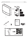
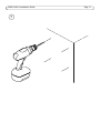
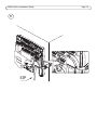
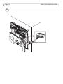
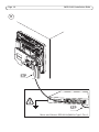
INSTALLATION GUIDE
AXIS A1001 Network Door Controller
Liability
Every care has been taken in the preparation of this
document. Please inform your local Axis office of any
inaccuracies or omissions. Axis Communications AB cannot
be held responsible for any technical or typographical errors
and reserves the right to make changes to the product and
manuals without prior notice. Axis Communications AB
makes no warranty of any kind with regard to the material
contained within this document, including, but not limited
to, the implied warranties of merchantability and fitness for
a particular purpose. Axis Communications AB shall not be
liable nor responsible for incidental or consequential
damages in connection with the furnishing, performance or
use of this material. This product is only to be used for its
intended purpose.
Intellectual Property Rights
Axis AB has intellectual property rights relating to
technology embodied in the product described in this
document. In particular, and without limitation, these
intellectual property rights may include one or more of the
patents listed at http://www.axis.com/patent.htm and one or
more additional patents or pending patent applications in
the US and other countries.
Equipment Modifications
This equipment must be installed and used in strict
accordance with the instructions given in the user
documentation. This equipment contains no user-serviceable
components. Unauthorized equipment changes or
modifications will invalidate all applicable regulatory
certifications and approvals.
System Considerations
The Axis product shall be installed within the secured area.
The Axis product, whether it is a standalone door controller
or a system of door controllers, shall not impair the intended
operation of the panic hardware used in conjunction with it.
The Axis product should be installed on a wall (preferred) or a
ceiling, with or without a junction box. It can also be
installed on a DIN rail.
Trademark Acknowledgments
AXIS COMMUNICATIONS, AXIS, ETRAX, ARTPEC and VAPIX
are registered trademarks or trademark applications of Axis
AB in various jurisdictions. All other company names and
products are trademarks or registered trademarks of their
respective companies.
Support
Should you require any technical assistance, please contact
your Axis reseller. If your questions cannot be answered
immediately, your reseller will forward your queries through
the appropriate channels to ensure a rapid response. If you
are connected to the Internet, you can:
• download user documentation and software updates
• find answers to resolved problems in the FAQ database.
Search by product, category, or phrase
• report problems to Axis support staff by logging in to your
private support area
• chat with Axis support staff (selected countries only)
• visit Axis Support at www.axis.com/techsup/
Learn More!
Visit Axis learning center www.axis.com/academy/ for useful
trainings, webinars, tutorials and guides.
Regulatory Information
Europe
This product complies with the applicable CE marking
directives and harmonized standards:
• Electromagnetic Compatibility (EMC) Directive
2004/108/EC. See Electromagnetic Compatibility (EMC).
• Low Voltage (LVD) Directive 2006/95/EC. See Safety.
• Restrictions of Hazardous Substances (RoHS) Directive
2011/65/EU. See Disposal and Recycling.
A copy of the original declaration of conformity may be
obtained from Axis Communications AB. See Contact
Information, on page 3.
Electromagnetic Compatibility (EMC)
This equipment has been designed and tested to fulfill
applicable standards for:
• Radio frequency emission when installed according to the
instructions and used in its intended environment.
• Immunity to electrical and electromagnetic phenomena
when installed according to the instructions and used in its
intended environment.
USA
This equipment has been tested using a shielded network
cable (STP) and found to comply with the limits for a Class B
digital device, pursuant to part 15 of the FCC Rules. These
limits are designed to provide reasonable protection against
harmful interference in a residential installation. This
equipment generates, uses and can radiate radio frequency
energy and, if not installed and used in accordance with the
instructions, may cause harmful interference to radio
communications. However, there is no guarantee that
interference will not occur in a particular installation. If this
equipment does cause harmful interference to radio or
television reception, which can be determined by turning the
equipment off and on, the user is encouraged to try to
correct the interference by one or more of the following
measures:
• Reorient or relocate the receiving antenna.
• Increase the separation between the equipment and
receiver.
• Connect the equipment into an outlet on a circuit different
from that to which the receiver is connected.
• Consult the dealer or an experienced radio/TV technician
for help.
Canada
This Class B digital apparatus complies with Canadian
ICES-003.
Europe
This digital equipment fulfills the requirements for RF
emission according to the Class B limit of EN 55022.
This product fulfills the requirements for immunity according
to EN 61000-6-1 residential, commercial and light-industrial
environments.
This product fulfills the requirements for immunity according
to EN 61000-6-2 industrial environments.
This product fulfills the requirements for immunity according
to EN 55024 office and commercial environments.
This product fulfills the requirements for immunity according
to EN 50130-4 residential, commercial, light-industrial and
industrial environments.
Australia/New Zealand
This digital equipment fulfills the requirements for RF
emission according to the Class B limit of AS/NZS CISPR 22.
Japan - この装置は、クラスB 情報技術装置です。
この装置は、家庭環境で使用することを目 的として
いますが、この装置がラジオやテレビジョン受信機
に近接して使用されると、 受信障害を引き起こすこ
とがあります。 取扱説明書に従って正しい取り扱い
をして下さい。
Safety
This product complies with IEC/EN/UL 60950-1, Safety of
Information Technology Equipment.
The power supply used with this product shall fulfill the
requirements for Safety Extra Low Voltage (SELV) and
Limited Power Source (LPS) to IEC/EN/UL 60950-1.
When used in systems that require UL certification, the
product shall be powered by a UL 294-listed or UL 603-listed
Class 2 low-voltage power limited power supply.
Disposal and Recycling
Europe
This symbol means that the product shall not be
disposed of together with household or commercial
waste. Directive 2012/19/EU on waste electrical
and electronic equipment (WEEE) is applicable in
the European Union member states. To prevent
potential harm to human health and the environment, the
product must be disposed of in an approved and
environmentally safe recycling process. For information
about your nearest designated collection point, contact your
local authority responsible for waste disposal. Businesses
should contact the product supplier for information about
how to dispose of this product correctly. This product
complies with the requirements of Directive 2011/65/EU on
the restriction of the use of certain hazardous substances in
electrical and electronic equipment (RoHS).
China
This product complies with the requirements of the
legislative act Administration on the Control of
Pollution Caused by Electronic Information Products
(ACPEIP).
Contact Information
Axis Communications AB
Emdalavägen 14
223 69 Lund
Sweden
Tel: +46 46 272 18 00
Fax: +46 46 13 61 30
www.axis.com
Safety Information
Read through this Installation Guide carefully before
installing the product. Keep the Installation
Guide for future reference.
Hazard Levels
Read through this Installation Guide carefully before
installing the Axis product. Keep the Installation Guide for
further reference.
Indicates a hazardous situation which, if not avoided, will
result in death or serious injury.
Indicates a hazardous situation which, if not avoided, could
result in death or serious injury.
Indicates a hazardous situation which, if not avoided, could
result in minor or moderate injury.
Indicates a situation which, if not avoided, could result in
damage to property.
Other Message Levels
Indicates significant information which is essential for the
product to function correctly.
Indicates useful information which helps in getting the most
out of the product.
Safety Instructions
The Axis product shall be installed by a trained professional.
• Never mount or make connections to the Axis product
while power is applied to the product. Always apply power
at the end of the installation.
• The Axis product shall be used in compliance with local
laws and regulations.
• To use the Axis product outdoors, or in similar
environments, it shall be installed in an approved outdoor
housing.
• Store the Axis product in a dry and ventilated environment.
• Avoid exposing the Axis product to vibration, shocks or
heavy pressure.
• Do not install the product on unstable or vibrating
brackets, surfaces or walls.
• Use only applicable tools when installing the Axis product.
Excessive force could cause damage to the product.
• Do not use chemicals, caustic agents, or aerosol cleaners.
Use a damp cloth for cleaning.
• Use only accessories that comply with technical
specification of the product. These can be provided by Axis
or a third party.
• Use only spare parts provided by or recommended by Axis.
• Do not attempt to repair the product by yourself. Contact
Axis support or your Axis reseller for service matters.
• The product shall be connected using a shielded network
cable (STP). All cables connecting the product to the
network switch shall be shielded (STP) and intended for
their specific use. Make sure that the network switch is
properly grounded. For information about regulatory
requirements, see Regulatory Information, on page 2.
• Use a Safety Extra Low Voltage (SELV) compliant limited
power source (LPS) with either a rated output power
limited to ≤100 W or a rated output current limited to
≤5 A.
• Each wire shall have an area that corresponds to AWG 28–
16 (CSA) or AWG 30–14 (CUL/UL). Select cables in
compliance with your local regulations.
• To allow for future maintenance, to avoid excessive strain
on wires and connectors, and to avoid damage to
conductor insulation, leave a service loop and make sure all
cables and wires are properly supported and secured. Use
the supplied cable ties.
• Make sure all the wires are connected correctly. Incorrect
wiring could cause damage to the product.
• To protect the circuits against electrostatic discharge
(ESD), use ESD protection when handling the product while
the components and contacts are exposed.
• If using Power over Ethernet, wait with connecting the
network cable to the network until the all the other wires
have been connected.
• If installing the door controller on a wall, make sure the
cut-out for the cables is facing downwards.
• The recommended maximum RS485 cable length is 30 m
(98.4 ft).
• Before installing the product, connect the product to the
network and configure the hardware in the product’s
hardware configuration pages. Use the generated hardware
pin chart. Make sure the product is disconnected from
power (PoE/DC) while connecting devices to the product.
• For information about how to connect other wires, such as
power wires to locks, readers and other devices, see the
manufacturers’ instructions.
Transportation
• When transporting the Axis product, use the original
packaging or equivalent to prevent damage to the product.
Battery
The Axis product uses a 3.0 V CR2032 lithium battery as the
power supply for its internal real-time clock (RTC). Under
normal conditions this battery will last for a minimum of five
years.
Low battery power affects the operation of the RTC, causing
it to reset at every power-up. A log message will appear
when the battery needs replacing.
The battery should not be replaced unless required, but if the
battery does need replacing, contact Axis support at
www.axis.com/techsup/ for assistance.
• Risk of explosion if the battery is incorrectly replaced.
• Replace only with an identical battery or a battery which is
recommended by Axis.
• Dispose of used batteries according to local regulations or
the battery manufacturer's instructions.
AXIS A1001 Installation Guide
Page 5
1x
5x
5x
1x
Owner Authentication Key
The authentication key on this label is used to authenticate the owner/administrator of
the product’s unique serial number (S/N), as
shown at the top of the label. The authentication key is used for registering the product
with an AVHS service provider for hosted services. For more information and help to find
a local AVHS Service Provider, go to:
http://www.axis.com/products/avhs/
Please keep this document for future reference.
Label here
©2006-2013 Axis Communications AB.
Axis is a registered trademark. All other company names and products are
trademarks or registered trademarks of their respective companies. We
reserve the right to introduce modifications without notice.
4x
1x
Part No. 52232
1x
www.axis.com/techsup
2x
Page 6
1
AXIS A1001 Installation Guide
AXIS A1001 Installation Guide
2
Page 7
Page 8
AXIS A1001 Installation Guide
3
STP
STP
Power over Ethernet IEEE 802.3af/802.3at Type 1 Class 3
AXIS A1001 Installation Guide
Page 9
4
192.168.0.90
AXIS IP Utility
www.axis.com/techsup
Page 10
5
6
AXIS A1001 Installation Guide
AXIS A1001 Installation Guide
7
Page 11
Page 12
8
AXIS A1001 Installation Guide
AXIS A1001 Installation Guide
9
STP
Page 13
Page 14
10
AXIS A1001 Installation Guide
AXIS A1001 Installation Guide
Reader I/O connectors
DC output: 12 V DC, max 300 mA
2x 4 configurable inputs/outputs:
Digital input: 0 to max 40 V DC
Digital output: 0 to max 40 V DC,
open drain, 100 mA
READER I/0 1 &2
Page 15
AWG 28–16 (CSA)
AWG 30–14 (CUL/UL)
Power & Relay connector
DC output: 12 V DC, max 500 mA
Relay: 30 V DC, max 700 mA
RELAY & PWR
Power lock connector
2x 12 V DC
0 V DC, floating, or 12 V DC,
max total load: 500 mA
LOCK
Power connector
DC input: 10–30 V DC,
max 26 W
Max load on
outputs: 14 W
DC IN
Auxiliary connector
DC output: 3.3 V DC, max 100 mA
Digital input: 0 to max 40 V DC;
Digital output: 0 to max 40 V DC,
open drain, 100 mA
AUX
Reader data connectors
Max cable length: 30 m (98.4 ft)
RS485 full duplex
RS485 half duplex
Wiegand
READER DATA 1 & 2
Door connectors
Digital input: 0 to max 40 V DC
DOOR IN 1 &2
Network Connector
RJ45, PoE IEEE 802.3af/
802.3at Type 1 Class 3
Max load on outputs: 7.5 W
Page 16
AXIS A1001 Installation Guide
11
STP
STP
Power over Ethernet IEEE 802.3af/802.3at Type 1 Class 3
AXIS A1001 Installation Guide
12
Page 17
Page 18
AXIS A1001 Installation Guide
13
T10
www.axis.com/warranty
Installation Guide
AXIS A1001 Network Door Controller
© Axis Communications AB, 2013
Ver.1.1
Printed: November 2013
Part No. 54595