1
BUNN
®
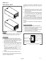
SYSTEM III
DISCONTINUED VERSION
The information in this manual
is no longer current.
OPERATING & SERVICE MANUAL
BUNN-O-MATIC CORPORATION
POST OFFICE BOX 3227
SPRINGFIELD, ILLINOIS 62708-3227
PHONE: (217) 529-6601 FAX: (217) 529-6644
27362.0000B 9/00 ©1996 Bunn-O-Matic Corporation
®
WARRANTY
Bunn-O-Matic Corp. (“Bunn”) warrants the equipment manufactured by it to be commercially free from defects
in material and workmanship existing at the time of manufacture and appearing within one year from the date of
installation. In addition:
1.) Bunn warrants electronic circuit and/or control boards to be commercially free from defects in material and
workmanship for two years from the date of installation.
2.) Bunn warrants the compressor on refrigeration equipment to be commercially free from defects in material
and workmanship for two years from the date of installation.
3.) Bunn warrants that the grinding burrs on coffee grinding equipment will grind coffee to meet original factory
screen sieve analysis for three years from date of installation or for 30,000 pounds of coffee, whichever comes first.
This warranty does not apply to any equipment, component or part that was not manufactured by Bunn or that,
in Bunn’s judgement, has been affected by misuse, neglect, alteration, improper installation or operation, improper
maintenance or repair, damage or casualty.
THE FOREGOING WARRANTY IS EXCLUSIVE AND IS IN LIEU OF ANY OTHER WARRANTY, WRITTEN OR
ORAL, EXPRESS OR IMPLIED, INCLUDING, BUT NOT LIMITED TO, ANY IMPLIED WARRANTY OF EITHER
MERCHANTABILITY OR FITNESS FOR A PARTICULAR PURPOSE. The agents, dealers or employees of Bunn are
not authorized to make modifications to this warranty or to make additional warranties that are binding on Bunn.
Accordingly, statements by such individuals, whether oral or written, do not constitute warranties and should not
be relied upon.
The Buyer shall give Bunn prompt notice of any claim to be made under this warranty by telephone at (217)
529-6601 or by writing to Post Office Box 3227, Springfield, Illinois, 62708-3227. If requested by Bunn, the Buyer
shall ship the defective equipment prepaid to an authorized Bunn service location. If Bunn determines, in its sole
discretion, that the equipment does not conform to the warranty, Bunn shall repair the equipment with no charge
for parts during the warranty period and no charge for labor by a Bunn Authorized Service Representative during
the warranty period. If Bunn determines that repair is not feasible, Bunn shall, at its sole option, replace the
equipment or refund the purchase price for the equipment.
THE BUYER’S REMEDY AGAINST BUNN FOR THE BREACH OF ANY OBLIGATION ARISING OUT OF THE SALE
OF THIS EQUIPMENT, WHETHER DERIVED FROM WARRANTY OR OTHERWISE, SHALL BE LIMITED, AS
SPECIFIED HEREIN, TO REPAIR OR, AT BUNN’S SOLE OPTION, REPLACEMENT OR REFUND.
In no event shall Bunn be liable for any other damage or loss, including, but not limited to, lost profits, lost sales,
loss of use of equipment, claims of Buyer’s customers, cost of capital, cost of down time, cost of substitute
equipment, facilities or services, or any other special, incidental or consequential damages.
Page 2
27362 092500
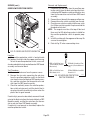
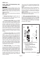
USER NOTICES
Carefully read and follow all notices in this manual and on the equipment. The notices on this brewer should
be kept in good condition. Replace any unreadable or damaged labels.
12364.0000
10044.0000
! WARNING
HOT WATER
20201.5600
00831.0000
03408.0000
00656.0000
03409.0000
Page 3
27362 092900
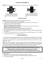
ELECTRICAL REQUIREMENTS
CAUTION - The brewer must be disconnected from the power source until specified in Initial Set-Up.
L2RED
WHITE
NEUTRAL
L2 RED
120V.A.C.
208 or 240V.A.C.
L1 BLACK
200 OR 240V.A.C.
120V.A.C.
BLACK
P2185
P1841
"A" & "B" models require 2-wire,
grounded service rated 200 volts ac
or 240 volts ac, 20 amp, single phase,
50 Hz.
Requires 3-wire, grounded service rated 120/208 volts or 120/240
volts ac, 20 amp, single phase, 60
Hz.
Electrical Hook-Up
CAUTION – Improper electrical installation will damage electronic components.
1. An electrician must provide electrical service as specified.
2. Using a voltmeter, check the voltage and color coding of each conductor at the electrical source.
3. Remove the front panel beneath the sprayhead.
Models with digital brewer control assembly:
Place the tank heater toggle switch at the bottom left of the control assembly in the "OFF" position.
Models with electro/mechanical thermostats:
Rotate the control thermostat knob fully counterclockwise to the "OFF" position.
4. Feed the cord through the strain relief and connect it to the terminal block.
5. Connect the brewer to the power source and verify the voltage at the terminal block before proceeding. Replace
the front panel.
6. If plumbing is to be hooked up later be sure the brewer is disconnected from the power source. If plumbing
has been hooked up, the brewer is ready for Initial Set-Up.
PLUMBING REQUIREMENTS
This brewer must be connected to a cold water system with operating pressure between 20 (138) and 90 psi
(620 kPa) from a 1⁄2" or larger supply line. A shut-off valve should be installed in the line before the brewer. Install
a regulator in the line when pressure is greater than 90 psi (620 kPa) to reduce it to 50 psi (345 kPa). The water
inlet fitting is 3⁄8" flare.
NOTE – Bunn-O-Matic recommends 3⁄8" copper tubing for installations of less than 25 feet and 1/2" for more than
25 feet from the 1⁄2" water supply line. A tight coil of copper tubing in the water line will facilitate moving the brewer
to clean the countertop. Bunn-O-Matic does not recommend the use of a saddle valve to install the brewer. The
size and shape of the hole made in the supply line by this type of device may restrict water flow.
This equipment must be installed to comply with the Basic Plumbing Code of the
Building Officials and Code Administrators International, Inc. (BOCA)
and the Food Service Sanitation Manual of the Food and Drug Administration (FDA).
Plumbing Hook-Up
1. Remove the 3⁄8" flare cap from the bulkhead fitting on the bottom of the brewer.
2. Flush the water line and securely attach it to the bulkhead fitting on the bottom of the brewer.
3. Turn on the water supply.
Page 4
27362 092900
INITIAL SET-UP
CAUTION – The brewer must be disconnected from the power source throughout the initial set-up, except when
specified in the instructions.
1. Remove the front panel beneath the sprayhead.
Models with digital brewer control assembly:
Place the tank heater toggle switch at the bottom left of the control assembly in the "OFF" position.
Models with electro/mechanical thermostats:
Rotate the control thermostat knob fully counterclockwise to the "OFF" position.
2. Connect the brewer to the power source. Water will begin flowing into the tank.
3. When water stops flowing into the tank, remove the front panel and proceed as directed.
Models with digital brewer control assembly:
Place the tank heater toggle switch at the bottom left of the control assembly in the "ON" position and replace
the front panel.
Models with electro/mechanical thermostats:
Rotate the control thermostat knob fully clockwise to the "ON" position and replace the front panel.
4. On 208V or 240V Models , wait approximately twenty-five minutes for the water in the tank to heat to the proper
temperature.
5. Place an empty server beneath the brew station. Place the Selector switch in the desired position, the ON/OFF
switch in the "ON" (upper) position and initiate a brew cycle. Each volume must be set individually.
6. Place the ON/OFF switch in the "OFF" (lower) position after water has stopped flowing from the funnel, and check
the water volume in the server. It should be 128 oz (1 gallon), 192 oz (1-1/2 gallon) or 256 oz (2 gallon).
7. (A) If not, adjust the brew timer as required. See Adjusting Brew Volumes for electro/mechanical brewers. See
Service - Digital Brewer Control Board for DBC Brewers. Allow the water to reheat, start, and measure another
brew cycle.
(B) If necessary adjust the needle valve to achieve water volume to be bypassed around the coffee filter in the
funnel.
NOTE: To increase the water bypass turn the needle valve counterclockwise, to decrease the water bypass turn
the needle valve clockwise. An adjustment to the needle valve will require a timer adjustment for desired
volume.
8. Repeat step 7 until the proper water volume is achieved.
9. The brewer is now ready for use in accordance with the coffee brewing instructions.
ADJUSTING BREW VOLUMES
electro/mechanical brewers
CAUTION - Disconnect the power source from the brewer prior to the removal of any panel for the replacement
or adjustment of any component.
NOTE: Prior to setting or modifying batch sizes, check that the brewer is connected to water supply, the tank is
properly filled, and a funnel and server are in place.
1. Modifying batch sizes. To modify a batch volume, first check that the SET/LOCK switch is in the “SET”
position on the circuit board. Select the batch volume to be set. (1, 1-1/2, or 2 gallons)
NOTE: Each batch setting must be adjusted separately.
To increase a batch size. Press and hold the START or BREW switch until three clicks are heard. Release the
switch (Failure to release the switch within two seconds after the third click causes the volume setting to be
aborted and previous volume setting will remain in memory) and press it again one or more times. Each time
the switch is pressed, two seconds are added to the brew time period. Allow the brew cycle to finish in order
to verify that the desired volume has been achieved.
Page 5
27362 092900
ADJUSTING BREW VOLUMES (cont.)
To decrease a batch size. Press and release the START or BREW switch once for every two-second interval
to be removed from the total brew time period; then immediately press and hold down the START or BREW
switch until three clicks are heard. Release the switch. (Failure to release the switch within two seconds after
the third click causes the volume setting to be aborted and previous volume setting will remain in memory).
Allow the brew cycle to finish in order to verify that the desired volume has been achieved.
2. Setting batch sizes. To set a batch volume, first check that the SET/LOCK switch is in the "SET" position on
the circuit board. Press and hold the START or BREW switch until three distinct clicks are heard, and then
release the switch. (Failure to release the switch within two seconds after the third click causes the volume
setting to be aborted and previous volume setting will remain in memory). View the level of the liquid being
dispensed. When the desired level is reached, turn the ON/OFF switch to "OFF" (lower). The brewer remembers this volume and will continue to brew batches of this size until the volume setting procedure is repeated.
NOTE: When brewing coffee, batch volumes will decrease due to absorption by the coffee grounds.
3. Setting programming disable feature. If it becomes necessary to prevent anyone from changing brew times
once programmed, you can set the SET/LOCK switch to the "LOCK" position. This will prevent any programming to be done until switch is once again placed in the "SET" position.
OPERATING CONTROLS
BREW SELECTOR SWITCH
Placing the switch in the 1Gal, 1-1/2Gal or 2Gal position selects the amount of coffee to be brewed in
subsequent brew cycles. Repositioning this switch after a brew cycle has been initiated does not change the brew
batch in progress.
ON/0FF (Warmer) SWITCH
Placing the switch in the unlighted lower position cuts power to the brew station warmer and stops brewing.
Stopping a brew cycle after it has been started will not stop the flow of water from the funnel. Placing the switch
in the lighted upper position supplies power to the brew station warmer and enables the brew circuit.
START SWITCH
Momentarily pressing and releasing this switch starts a brew cycle when the ON/OFF switch is in the lighted
upper position.
NOTE – The ON/OFF switch must be in the lighted upper position to initiate and complete a brew cycle.
COFFEE BREWING
1.
2.
3.
4.
5.
6
7.
Select the desired batch size.
Insert a BUNN® filter into the funnel.
Pour the proper amount of fresh coffee into the filter and level the bed of grounds by gently shaking.
Slide the funnel into the funnel rails.
Place an empty server under the funnel.
Place the ON/OFF switch in the lighted upper position. Momentarily press and release the Start switch.
When brewing is complete, simply discard the grounds and filter.
CLEANING
1. The use of a damp cloth rinsed in any mild, nonabrasive, liquid detergent is recommended for cleaning all
surfaces on Bunn-O-Matic equipment.
2. Check and clean the sprayhead. The sprayhead holes must always remain open.
NOTE – In hard water areas, this may need to be done daily. It will help prevent liming problems in the brewer and
takes less than a minute.
27362 092900
Page 6
TROUBLESHOOTING
A troubleshooting guide is provided to suggest probable causes and remedies for the most likely problems
encountered. If the problem remains after exhausting the troubleshooting steps, contact the Bunn-O-Matic
Technical Service Department.
•
•
•
•
•
•
•
WARNING
•
•
•
•
Inspection, testing, and repair of electrical equipment should be performed only by qualified service
personnel.
All electronic components have 120 - 240 volt ac and low voltage dc potential on their terminals.
Shorting of terminals or the application of external voltages may result in board failure.
Intermittent operation of electronic circuit boards is unlikely. Board failure will normally be
permanent. If an intermittent condition is encountered, the cause will likely be a switch contact or
a loose connection at a terminal or crimp.
Solenoid removal requires interrupting the water supply to the valve. Damage may result if
solenoids are energized for more than ten minutes without a supply of water.
The use of two wrenches is recommended whenever plumbing fittings are tightened or loosened.
This will help avoid twists and kinks in the tubing.
Make certain that all plumbing connections are sealed and electrical connections tight and isolated.
This brewer is heated at all times. Keep away from combustibles.
Exercise extreme caution when servicing electrical equipment.
Disconnect power source when servicing, except when electrical tests are specified.
Follow recommended service procedures.
Replace all protective shields or safety notices.
Problem
Probable Cause
Remedy
Equipment will not operate.
1. No power or incorrect voltage
(A1) Check the terminal block for
120 volts across the red and white
terminals and the black and white
terminals on 120/208 or 120/240
volt brewers.
(A2) Check the terminal block for
200 volts on "B Series" brewers or
240 volts on "A Series" brewers
across the red and black terminals.
(B) Check circuit breakers or fuses.
Brew cycle will not start.
1. No water
Check plumbing and shut-off valves
2. Water strainer/flow control (.500
GPM)
(A) Direction of flow arrow must be
pointing towards the right.
(B) Remove the strainer/flow
control and check for obstructions.
Clear or replace.
Page 7
27362 092996
TROUBLESHOOTING (cont.)
Problem
Probable Cause
Remedy
Brew cycle will not start (cont.)
3. ON/OFF switch
Refer to Service - ON/OFF switch for
testing procedures. See page 28
4. Start switch
Refer to Service - Start switch for
testing procedures. See page 32
5. Timer
Refer to Service - Timer for testing
procedures. See page 34 or 35
6. Dispense Valve
Refer to Service - Dispense valve for
testing procedures. See page 21
7. Digital Brewer Control
Refer to Service - Digital brewer
controls for testing procedures. See
page 22 step 4
1. No water
Check plumbing and shut-off valves.
2. Water strainer/flow control (.500
GPM)
(A) Direction of flow arrow must be
pointing towards the right.
Automatic refill will not operate
(B) Remove the strainer/flow control and check for obstructions. Clear
or replace.
3. Limit thermostat (Electro/mechanical and Digital Brewer Control)
Refer to Service - Limit thermostat
for testing procedures. See page 27
4. Overflow protection switch
Refer to Service - Overflow protection switch for testing procedures.
See page 29
5. (A) Level control board & level
probe. (Electro/mechanical)
Refer to Service - Level control board
for testing procedures. See page 25
(B) Digital Brewer Control Assembly (DBC)
Refer to Service - Digital brewer
control for testing procedures. See
page 22 step 2
Page 8
27362 092900
TROUBLESHOOTING (cont.)
Problem
Probable Cause
Remedy
Automatic refill will not operate 6. Solenoid Valve
(cont.)
Refer to Service - Solenoid valve for
testing procedures. See page 30
Beverage level will not adjust (Selec- 1. Selector switch
tor switch in any position)
Refer to Service - Selector switch for
testing procedures. See page 16
Water flows into tank continuously
(ON/OFF Switch "OFF")
Refer to Service - Level control board
for testing procedures. See page 25
Water from tank is not hot
1. (A) Level control board and level
probe (Electro/mechanical)
(B) Digital Brewer Control
Refer to Service - Digital brewer
control for testing procedures. See
page 23 step 10
2. Overflow protection switch
Refer to Service - Overflow protection switch for testing procedures.
See page 29
3. Solenoid valve
Refer to Service - Solenoid valve for
testing procedures. See page 30
1. Limit thermostat
CAUTION - Do not eliminate or bypass limit thermostat. Use only
B.O.M. part #23717.0001
Refer to Service -Limit thermostat
for testing procedures. See page 27
2. (A) Control Thermostat (Electro/
mechanical)
Refer to Service - Control thermostat for testing procedures. See page
20
(B) Digital Brewer Control
Refer to Service - Digital brewer
control for testing procedure. See
page 22 step 3
3. Contactor (Electro/mechanical)
Refer to Service - Contactor for test
procedures. See page 18
4. Tank heater
Refer to Service - Tank heater for
testing procedures. See page 33
Page 9
27362 092900
TROUBLESHOOTING (cont.)
Problem
Probable Cause
Remedy
Water from tank is not hot (cont.)
5. Triac assembly (DBC)
Refer to Service - Digital brewer control for testing procedures. See page
22
Server warmer is not hot.
1. ON/OFF switch
Refer to Service - ON/OFF switch for
testing procedures. See page 28
2. Warmer element
Refer to Service - Warmer element
for testing procedures. See page 37
1. (A) Control thermostat (Electro/
mechanical)
Refer to Service - Control thermostat for testing procedures. See page
20
Spitting or unusual steaming from
sprayhead or airvent.
(B) Digital Brewer Control
2. Triac assembly (DBC)
Refer to Service - Digital Brew Control for testing procedures. See page
22
3. Lime build-up
Inspect the tank assembly for excessive lime deposits. Delime as required.
CAUTION - Tank and tank components should be delimed regularly
depending on local water conditions.
Excessive mineral build-up on stainless steel surfaces can initiate corrosive reactions resulting in serious
leaks.
Inconsistent beverage level in server.
Refer to Service - Digital brewer control for testing procedures. See page
23 step 10
1. Strainer/flow control (.500 GPM)
(A) Direction of flow arrow must be
pointing towards the brewer.
2. Improper water pressure
(B) Remove the strainer/flow control and check for obstructions. Clear
or replace.
Check the operating water pressure
to the brewer. It must be between 20
(138) and 90 psi (620 kPa).
Page 10
27362 092900
TROUBLESHOOTING (cont.)
Problem
Probable Cause
Remedy
Inconsistent beverage level in server.
(cont.)
3. Dispense valve
Refer to Service - Dispense valve for
testing procedures. See page 21
Consistently high or low beverage
level in server.
1. (A) Time adjustment (Electro/ Refer to Service - Brew Timer for
mechanical)
testing and adjustment procedures.
See pages 34 or 35
(B) DBC volume adjustment
Refer to Service - Digital brewer
control for testing procedures. See
page 23 step 8
Dripping from sprayhead.
1. Dispense valve
Water overflows filter.
1. Bypass valve (Electro/mechani- Refer to Adjustments on page 5 step
cal)
#7. For test procedures see page 15.
Beverage overflows server.
Weak beverage.
Refer to Service - Dispense valve
for testing procedures. See page 21
2. Type of paper filters
BUNN® paper filters should be used
for proper extraction.
3. No sprayhead
Check sprayhead
1. Beverage left in server
The brew cycle should be started
only with an empty server under the
funnel.
2. Timer adjustment
Refer to Service - Timer for testing
procedures. See page 34 or 35
3. Dispense valve
Refer to Service - Dispense valve for
testing procedures. See page 21
1. Type of paper filters
BUNN® paper filters should be used
for proper extraction.
2. Coffee
A sufficient quantity of fresh drip or
regular grind should be used for
proper extraction.
Page 11
27362 092900
TROUBLESHOOTING (cont.)
Problem
Probable Cause
Remedy
Weak beverage (cont.)
3. Sprayhead
B.O.M. sprayhead #01082.0002
should be used to properly wet the
bed of ground coffee in the funnel.
4. Funnel loading
The BUNN® paper filter should be
centered in the funnel and the bed of
ground coffee leveled by gentle shaking.
5. Water temperature
Empty the server, remove its cover,
and place the server on the warmer.
Place empty funnel over the server
entrance, with ON/OFF switch in the
"ON" (upper) position press the start
switch and release it. Check the water temperature immediately below
the sprayhead with a thermometer.
The reading should not be less than
195˚F (91˚C).
1. Solenoid (Inlet)
The nut on back of the solenoid must
be tight or it will vibrate during operation
2. Plumbing lines
Plumbing lines should not be resting on the counter top.
3. Water supply
(A) The brewer must be connected
to a cold water line.
Brewer is making unusual noises.
(B) Water pressure to the brewer
must not be higher than 90 psi (620
kPa). Install a regulator if necessary
to lower the working pressure to
approximately 50 psi (345 kPa).
Temperature on the DBC display
varies.
4. Tank heater
Remove and clean lime off the tank
heater.
5. Contactor
Check for low voltage.
1. Digital brewer control
Refer to Service - Digital brewer
control for testing procedures. See
page 22 step 6
Page 12
27362 092900
TROUBLESHOOTING (cont.)
Problem
Probable Cause
Remedy
Cannot access the DBC
1. Digital brewer control
Refer to Service - Digital brewer control for testing procedures. See page
22 step 7
DBC display is blank
1. Digital brewer control
Refer to Service - Digital brewer control for testing procedures. See page
23 step 9
Page 13
27362 092900
SERVICE
This section provides procedures for testing and
replacing various major components used in this
brewer should service become necessary. Refer to
Troubleshooting for assistance in determining the
cause of any problem.
WARNING - Inspection, testing, and repair of electrical equipment should be performed only by qualified
service personnel. The brewer should be unplugged
when servicing, except when electrical tests are required and the test procedure specifically states to
plug in the brewer.
COMPONENT ACCESS
WARNING - Disconnect the brewer from the power
source before the removal of any panel or the replacement of any component.
All components are accessible by the removal of
the top cover, front inspection panel and warmer base
plate.
The top cover is attached with four #6-32 screws.
The front inspection panel is attached with five
#6-32 screws.
The warmer base is attached with four #6-32
screws.
Contents
Brewer Selector Switch....................................... 16
Bypass Valve ...................................................... 15
Contactor Assembly............................................ 18
Control Thermostat ............................................. 20
Digital Brewer Control (DBC) .............................. 22
Dispense Valve ................................................... 21
Level Control Board and Level Probe .................. 25
Limit Thermostat ................................................ 27
ON/OFF Switch (Warmer) ................................... 28
Overflow Protection Switch ................................ 29
Solenoid (Refill) .................................................. 30
Start Switch (Brew) ............................................ 32
Tank Heater ........................................................ 33
Timer (Early Models) .......................................... 34
Digital Timer (Late Models) ................................ 35
Triac/Heat Sink ................................................... 24
Warmer Element ................................................. 37
Wiring Diagrams ................................................. 38
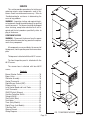
Page 14
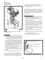
FIG. 1 COMPONENT ACCESS
P1095.40
27362 092900
SERVICE (cont.)
4. Disconnect the white/green wire and white/violet
wire. Check for continuity across the bypass valve
coil terminals.
BYPASS VALVE
LOCK
If continuity is present as described, reconnect the
white/green and white/violet wires to the bypass valve
and proceed to #5.
If continuity is not present as described, replace the
bypass valve.
LOCK
SET
SET
5. Check the bypass valve for coil action. Connect
brewer to the power source. With the "ON/OFF
(Warmer)" switch in the "ON" (upper)position press
the start switch. Listen carefully in the vicinity of
the bypass valve for a "clicking" sound as the coil
attracts and repels the plunger.
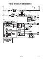
J2
TL1
TL2
TL4
TL3
TL5
J1
FLOW
sure
gpm pres
00
.500
0.05
ating
2230
500)
#
oper
rol
26.0
max
NN
Cont
#205 000)
psig
low
90
BU
her
21.0
ner/F
Strai
Was
en
l. Flow
l. Scre
(Rep
(Rep
#237
T WA
HO
!
CA
UT
TE
If the sound is heard as described, there may be a
blockage in the water line before the bypass valve or
the bypass valve may require inspection for wear and
removal of waterborne particles.
If the sound is not heard as described, replace the
bypass valve.
R
ION
FIG. 2 BYPASS VALVE
P2231.35
Location:
The bypass valve is located inside the hood on the
left side just in front of the tank.
Test Procedures:
1. Disconnect the brewer from the power source.
2. With a voltmeter, check the voltage across the
white/green wire and the white/violet wire on the
bypass valve. Connect the brewer to the power
source. With the "ON/OFF (Warmer)" switch in the
"ON" (upper) position, and the selector switch in
the 1-1/2 or 2 gallon position press the start
switch. The indication must be:
a.) 120 volts ac for three wire 120/208 volt models
and three wire 120/240 volt models.
b.) 200 to 240 volts ac for two wire 200 or 240 volt
models.
3. Disconnect the brewer from the power source.
Removal and Replacement:
1. Remove the wires from the bypass valve.
2. Drain enough water from the tank so bypass valve
is above the water line.
3. Remove water lines from valve.
4. Remove two nuts retaining bypass valve inside the
hood and remove bypass valve.
5. Install new bypass valve.
6. Reconnect the water tubes and the wires to the
bypass valve.
7. Refer to FIG. 3 when reconnecting the wires.
If voltage is present as described, proceed to #4.
If voltage is not present as described refer to the
Wiring Diagrams and check the brewer wiring harness.
Page 15
WHI/VIO to Brew Selector Switch
WHI/GRN to Dispense Valve
FIG. 3 BYPASS VALVE TERMINALS
P1096
27362 092900
5. Reattach the connector to the brew timer circuit
board or DBC connector.
SERVICE (cont.)
BREW SELECTOR SWITCH
Grinder Interface:
6. Disconnect pink, gray and tan wires on the selector
switch from the pink, gray and tan wires on the
interface socket.
7. Check for continuity across the pink wire and the
tan wire on the selector switch when the switch is
in the 1 gallon position. Continuity must not be
present in any other position.
8. Check for continuity across the pink wire and gray
wire on the selector switch when the switch is in
the 1-1/2 gallon position. Continuity must not be
present in any other position.
9. Reconnect the pink, gray and tan wires on the
selector switch to the pink, gray and tan wires on
the interface socket.
FIG. 4 BREW SELECTOR SWITCH
P1097.40
Location:
The brew selector switch is located in the front of
the hood on the lower right side on DBC models and to
the right of center on electro/mechanical models.
Test Procedure:
Timer or DBC
1. Disconnect the brewer from the power supply.
2. Separate the connector on the selector switch
harness from the brew timer circuit board or DBC
connector.
3. Check for continuity across the pink and tan wires
on the connector when the switch is in the 1 gallon
position. Continuity must not be present in any
other position.
4. Check for continuity across the pink wire and the
gray wire when the switch is in the 1-1/2 gallon
position. Continuity must not be present in any
other switch position.
Bypass Valve:
10. Disconnect the white/violet wire on the selector
switch from the bypass valve coil and disconnect
the white/red wire from the dispense valve coil.
11. Check for continuity across the white/violet wire
and white/red wire when the selector is in the 1-1/
2 gallon and 2 gallon position. Continuity must not
be present in any other position.
12. Reconnect the white/violet wire to the bypass
valve coil and the white/red wire to the dispense
valve coil.
If continuity is as described the switch is operating
properly.
If continuity is not present as described replace switch
assembly.
Removal and Replacement:
1. Disconnect the connector on the selector switch
harness from the brewer timer circuit board.
2. Disconnect wires from the selector switch, interface socket, dispense valve and bypass valve.
3. Loosen the set screw on the switch knob.
4. Remove the 9/16" nut and washer holding the
switch to the hood.
5. Remove the switch.
6. Install the new switch. The positioning tab must be
in the hole in the hood for proper switch and knob
alignment.
Page 16
27362 092996
SERVICE (cont.)
BREW SELECTOR SWITCH (cont.)
7. Install the knob so that the arrow lines up in the 2
gallon position when the switch is turned to the full
right position.
8. Reattach the connector to the brew timer circuit
board or DBC
9. Refer to Fig. 5 when reconnecting the wires.
WHI/VIO to By-Pass Valve
To Timer (Electro/mechanical Models)
WHI/RED to Dispense Valve
GRY to GRY Lead on Interface
Socket
PNK to PNK Lead on Interface
Socket
TAN to TAN Lead on Interface
Socket
TAN
GRY
PNK
ELECTRO/MECHANICAL
P1105.75
WHI/VIO to By-Pass Valve
To DBC Board (Digital Brewer Controlled Models)
WHI/RED to Dispense Valve
PNK
TAN
GRY to GRY Lead on Interface
Socket
GRY
PNK to PNK Lead on Interface
Socket
TAN to TAN Lead on Interface
Socket
DIGITAL CONTROL (DBC)
FIG. 5 BREW SELECTOR SWITCH TERMINALS
Page 17
P1112.75
27362 092996
SERVICE (cont.)
CONTACTOR ASSEMBLY (ELECTRO/MECHANICAL
ONLY)
b.) 200 to 240 volts ac for two wire 200 or 240 volt
models.
5. Disconnect the brewer from the power source.
If voltage is present as described, proceed to #6.
If voltage is not present as described, refer to the
Wiring Diagrams and check the brewer wiring harness.
6. Check for continuity between the two black wires
of the contactor coil.
LOCK
If continuity is present as described, reconnect one
black wire to the white wire or red wire from the
terminal block and the other black wire to the black
wire from the control thermostat. Reinstall capillary
tube into tank to line 7" above the bulb and proceed to
#7.
If continuity is not present as described, replace the
contactor.
LOCK
SET
SET
J2
TL1
TL2
TL4
TL3
TL5
J1
FLOW
sure
gpm pres
00
.500
0.05
ating
2230
500)
#
oper
rol
26.0
NN
max
Cont
#205 000)
psig
low
90
BU
her
21.0
ner/F
Strai
Was
en
l. Flow
l. Scre
(Rep
(Rep
#237
TE
T WA
HO
!
CA
UT
R
ION
FIG. 6 CONTACTOR ASSEMBLY
P2231.35
Location:
The contactor assembly is located inside the hood
to the right of the overflow cup.
Test Procedures:
Mechanical Thermostat
1. Disconnect the brewer from the power source.
2. Disconnect the white wire or the red wire and the
black wire of the contactor coil and disconnect the
black wire of the control thermostat from the
remaining black wire of the contactor coil.
3. Gently remove the capillary bulb and grommet
from the tank.
4. With a voltmeter, check the voltage across the
white wire from the terminal block on 120/208,
120/240 volt units or the red wire from 200, 240
volt units and the black wire from the control
thermostat when the thermostat is turned clockwise to the "FULL ON" position. Connect the brewer
to the power source. The indication must be:
a.) 120 volts ac for three wire 120/208 volt models
and three wire 120/240 volt models.
7. With a voltmeter, carefully check the voltage across
the red and black wires on L1 and L2. The indication must be:
a.) 208 volts ac for three wire 120/208 volt models
and 240 volts ac for three wire 120/240 volt
models.
b.) 200 to 240 volts ac for two wire 200 or 240 volt
models.
8. Disconnect the brewer from the power source.
If voltage is present as described, proceed to #9.
If voltage is not present as described, refer to the
Wiring Diagrams and check the brewer wiring harness.
9. Check for continuity across the terminals on the
left side of the contactor by manually closing the
contacts. Continuity must not be present when the
contact is released.
10. Check for continuity across the terminals on the
right side of the contactor by manually closing the
contacts. Continuity must not be present when the
contact is released.
If continuity is present as described, the contactor is
operating properly.
If continuity is not present as described, replace the
contactor.
Page 18
27362 092900
SERVICE (cont.)
CONTACTOR ASSEMBLY (ELECTRO/MECHANICAL
ONLY) (cont.)
Removal and Replacement:
1. Remove all wires from the contactor.
2. Remove the two #10-32 screws securing contactor
to the inside of the hood.
3. Securely install the new contactor inside the hood.
4. Refer to Fig. 7 when reconnecting the wires.
RED L1 to Terminal
Block (Red Insert)
BLK L2 to Limit Thermostat
BLK T2 to Tank Heater
RED T1 to Tank Heater
BLK to WHI Lead from the
Three Pole 120/208V or 120/
240V Terminal Block
BLK to RED Lead from the
Two Pole 200V or 240V Terminal Block
BLK to BLK Lead from Thermostat
MECHANICAL THERMOSTAT ONLY
P1113
FIG. 7 CONTACTOR ASSEMBLY TERMINALS
Page 19
27362 092900
b.) 200 to 240 volts ac for two wire 200 or 240 volt
models.
Voltage must not be indicated across these terminals when the thermostat is turned "OFF" (fully
counterclockwise).
6. Disconnect the brewer from the power source.
LOCK
SERVICE (cont.)
CONTROL THERMOSTAT (ELECTRO/MECHANICAL
ONLY)
LOCK
SET
SET
J2
If voltage is present as described, reinstall the capillary
tube into the tank to the line 7" above the bulb, the
control thermostat is operating properly.
If voltage is not present as described, replace the
thermostat.
TL1
TL2
TL4
TL3
TL5
J1
FLOWure
gpm press
0
.500 ting
0.050
opera
# 2230
00)
ol
26.05
NN
max
Contr
#205
psig
00)
w
er
90
BU
21.00
er/Flo
Strain
Wash
n #237
. Flow
. Scree
(Repl
(Repl
P2231.30
FIG. 8 CONTROL THERMOSTAT
Location:
The control thermostat is located inside the front
of the brewer in the center of the component bracket.
Test Procedures:
1. Disconnect the brewer from the power source.
2. With a voltmeter, check the voltage across the blue
wires on the control thermostat and the white
insert on the three pole 120/208V, 120/240V terminal block or the red insert on two pole 240V
terminal block. Connect the brewer to the power
source. The indication must be:
a.) 120 volts ac for three wire 120/208 volt models
and three wire 120/240 volt models.
b.) 200 to 240 volts ac for two wire 200 or 240 volt
models.
3. Disconnect the brewer from the power source.
Removal and Replacement:
1. Remove wires from the control thermostat.
2. Remove the thermostat capillary bulb by firmly
pulling up on the capillary tube on top of the tank
lid. This will disengage the grommet from tank lid.
3. Remove the #8-32 screw holding the control thermostat to the component bracket.
4. Slide the grommet to the line 7" above the bulb on
the new capillary tube.
5. Insert the capillary bulb through the hole in the
tank lid and press the grommet firmly and evenly
so that the groove in the grommet fits into the tank
lid.
6. Carefully bend the capillary tube so that the tube
and bulb inside the tank are in the vertical position.
NOTE - The capillary tube must be clear of any electrical termination and not kinked.
7. Using a #8-32 screw, fasten the control thermostat to the component bracket.
8. Refer to Fig. 9 when reconnecting the wires.
9. Adjust the control thermostat as required.
If voltage is present as described, proceed to #4.
If voltage is not present as described, refer to the
BLU to Ready Light
Wiring Diagrams and check the brewer wiring harBLU to RED Lead from Overflow
ness.
Protection Switch
4. Gently remove the capillary bulb and grommet
BLK to BLK Lead on Contactor Coil
BLK to Ready Light
from the tank.
5. With a voltmeter, check the voltage across the
black wires of the control thermostat and the white
insert on the three pole 120/208V or 120/240V
terminal blocks and the red insert on two pole
200V/240V terminal blocks when the control thermostat is turned "ON" (fully clockwise). Connect
the brewer to the power source. The indication
P1098
must be:
a.) 120 volts ac for three wire 120/208 volt models
FIG. 9 CONTROL THERMOSTAT TERMINALS
and three wire 120/240 volt models.
27362 092900
Page 20
SERVICE (cont.)
DISPENSE VALVE
5. Check the dispense valve for coil action. Connect
the brewer to power source. Place the "ON/OFF
(Warmer)" switch in the "ON" (upper) position,
press and release the start switch. Listen carefully
in the vicinity of the dispense valve for a "clicking"
sound as the coil magnet attracts and repels the
plunger.
6. Disconnect the brewer from the power source.
LOCK
If the sound is heard as described, there may be a
blockage in the dispense valve or the water line to the
dispense valve. Remove the dispense valve and inspect for wear, and remove waterborne particles.
If the sound is not heard as described, replace the
dispense valve.
LOCK
SET
SET
J2
TL1
TL2
TL4
TL3
TL5
J1
NNx
FLOW
sure
gpm pres
00
.500
0.05
ating
)
2230
l#
6 0500
oper
P2231.35
FIG. 10 DISPENSE VALVE
Location:
Dispense valve is located inside the hood directly
above the sprayhead.
Test Procedures:
1. Disconnect the brewer from the power source.
2. Disconnect the wires from the dispense valve and
check for continuity across the dispense valve coil
terminals.
If continuity is present as described, reconnect the
wires to the dispense valve and proceed to #3.
If continuity is not present as described, replace the
dispense valve.
Removal and Replacement:
1. Disconnect wires from dispense valve.
2. Drain enough water from the tank so the dispense
valve is above the water line.
3. Remove water lines and hose barb fitting from
dispense valve.
4. Remove dispense valve from the sprayhead panel.
5. Install new dispense valve .
6. Reconnect the water lines, hose barb fitting and
the wires to the dispense valve.
7. Refer to Fig. 11 when reconnecting wires.
3. With a voltmeter, check the voltage across dispense valve using the white/violet wire and white/
green wire on electro/mechanical models, or white/
red wire and white/green wire on DBC models.
Connect brewer to the power source. Place the
"ON/OFF (Warmer)" switch in the "ON" (upper)
position. Press and release the start switch. The
indication must be:
a.) 120 volts ac for three wire 120/208 volt models
and three wire 120/240 volt models.
b.) 200 to 240 volts ac for two wire 200 or 240 volt
models.
4. Disconnect brewer from the power source.
If voltage is present as described in step 3, proceed to
#5.
If voltage is not present as described, refer to the
Wiring Diagrams and check the brewer wiring harness.
Page 21
WHI/VIO to Timer TL1
WHI/VIO to ON/OFF Switch
WHI/RED to Brew Selector Switch
WHI/GRN to Timer TL4
WHI/GRN to By-Pass Valve
ELECTROMECHANICAL
WHI/RED to DBC Board J1-2
WHI/RED to Brew Selector Switch
WHI/GRN to Bypass Valve
WHI to DBC J1-3 (120/208 or 120/240 Volt
Models
RED to DBC J1-3 (200 or 240 Volt Models)
DIGITAL CONTROL (DBC)
P1106
FIG. 11 DISPENSE VALVE TERMINALS
27362 092900
SERVICE (cont.)
DIGITAL BREWER CONTROL BOARD AND DISPLAY
(DBC)
P1094.35
FIG. 12 DIGITAL CONTROL BOARD
Location
The digital control board is located inside the
upper front of the trunk on the component bracket.
The digital display is located in the upper center of
the front of hood.
NOTE: Check the function list (supplied) for FUNCTION, ENTRY AND DESCRIPTION.
1. If display indicates a "FAULT" use the list below to
troubleshoot the indicated fault.
FAULT 1 - main brew tank temperature probe is
shorted
FAULT 2 - main brew tank temperature probe is
open circuit
FAULT 3 - secondary water tank temperature
probe is shorted (used only in two-tank system)
FAULT 4 - secondary water tank temperature
probe is open circuit (used only in two-tank system)
FAULT 5 - main DBC board is defective
FAULT 6 - water overflow protection switch is
open circuit
FAULT 7 - dry plug-in condition (brewer is looking for connection between the water tank and the
dry plug-in probe.
2. If the brewer will not refill then use the function
list and test the refill solenoid and make sure that
the following functions are set properly.
A) set refill probe delay (larger values add more
delay time)
B) refill sensing probe ("no" means that there will
be no automatic refill)
C) refill solenoid separate from brew solenoid
(usually on gravity brewers) ("no" means that refill
will occur automatically only when not brewing.
D) set refill resistance threshold (only necessary
to change in pure water areas)(changing the setting to a value higher than 128 means the water will
be more likely to create a full condition).
E) check wiring to refill solenoid
F) replace Digital Brewer Control Board
3. If the brewer will not heat then check the following.
A) test the main tank heater
B) check the main brew tank temperature setting
C) check dry plug-in prevention probe setting
("yes" means that there must be a dry plug-in
prevention probe)
D) limit thermostat on top of the brewer tank
E) temporarily substitute a known working heater
triac assembly
F) replace Digital Brewer Control Board
4. If the brewer will not brew then use the function
list and test the brew solenoid and make sure that
the following functions are set properly.
A) set main brew tank temperature ( a setting that
is lower than the ready lamp value can prevent
brewing)
B) set main brew tank - ready lamp off temperature
(a setting that is higher than the brew value can
prevent brewing)
C) select brew lockout ("yes" requires the brewer
ready lamp to be "ON" in order to brew)
D) replace Digital Brewer Control Board
5. If the temperature reading on the display is higher
than 211˚F (99˚C), disconnect the two pin connector (blue wire and tan wire) from the heater triac.
If the heater remains on, the heater triac is defective and must be replaced.
B)
6. If the temperature on display varies by more than
one degree while the brewer is at idle, select main
Page 22
27362 092996
SERVICE (cont.)
DIGITAL BREWER CONTROL BOARD AND DISPLAY
(DBC) (cont.)
heater relay or triac. ("0" means the temperature
will be allowed to vary by the value in "set relay
temperature difference")
7. If you cannot access the DBC with the password
you have entered, the password has been changed.
If you know what the brew settings are you can
"reset" the memory back to the way it left the
factory, which is "0". This is accomplished by
disconnecting the brewer from the power source,
pressing the plus (+) and minus (-) buttons simultaneously and holding them in this position then
connecting the brewer to the power source. Continue pressing the buttons until the display shows
numbers counting upward rapidly. If this does not
occur press the plus (+) and minus(-) firmly and
repeat the procedure. The brew values can now be
set to your desired value.
8. If the brew volume does not match the programmed value then use the following list to
correct the error.
A) The coffee grounds naturally absorb some of
the brew water; typically between one and two
ounces of water per ounce of coffee (depending on
the grind).
B) The DBC calculates the amount of time the brew
solenoid must stay on to dispense the programmed
brew volume. It uses the sprayhead constant to
determine the rate of dispense. The sprayhead rate
can be measured by capturing the water coming
out of the sprayhead for 60 seconds. This value (in
gallons per minute) can be entered into memory.
C) The last reason can be the brew by-pass. If you
are using brew by-pass then the amount that
comes out of the by-pass must be subtracted from
the total desired volume to get the programmed
brew volume.
9. If your DBC display is blank, you should check the
following.
A) Make sure brewer is connected to the power
source.
B) Make sure connectors that go between the main
DBC and the DBC display are plugged into their
appropriate locations.
C) Restart the DBC program by disconnecting
brewer from the power source, wait 15 seconds
and reconnect the brewer to the power source.
D) If these do not remedy the problem, replace
Digital Brewer Control Board
10. If water is running out from the base of the brewer
check the following:
A) If the display shows temperature or FAULT 6 ,
disconnect the brewer from the power source. If
water continues to flow out of the base of the
brewer there may be an obstruction in the refill
solenoid valve. Refer to Refill Solenoid Valve service procedures.
B) With the brewer disconnected from the power
source, remove panels as necessary, dry inside of
brewer as needed, and reinstall panels on brewer.
C) Reconnect brewer to the power supply. If water
continues to flow out of the base, the Digital
Brewer Control Board is defective and must be
replaced.
Removal and Replacement:
DBC Control Board
1. Disconnect the brewer from the power source.
2. Disconnect all wires from the control board.
3. Remove the two #8-32 keps nuts securing control
board to component bracket inside the trunk.
4. Remove control board and discard,
5. Install new control board on the component bracket
using two #8-32 keps nuts.
6. Reconnect the multi-pin plugs to the control board.
DBC Display Assembly:
1. Disconnect the display assembly cord from the
display assembly.
2. Remove the two #6-32 locking screws securing
the display assembly to the display assembly
mounting bracket behind the front of the hood.
3. Remove display assembly from the front of the
hood and discard.
4. Install new display assembly on the front of the
hood using two #6-32 locking screws to secure it
to the display assembly mounting bracket.
5. Reconnect the display assembly cord to the display assembly.
NOTE: If necessary recalibrate the values of the
DBC using the FUNCTION LIST (supplied).
Page 23
27362 092900
SERVICE (cont.)
6. Apply heat sink compound and secure new triac
assembly on rear of the heat sink with one #6-32
screw.
7. Route the triac wires through the tank support
channel.
8. Secure triac/heat sink assembly to the lower rear
of the brewer with two #6-32 screws.
9. Reconnect the wires of the new triac assembly.
Refer to Fig. 14 when reconnecting wires.
TRIAC/HEAT SINK ASSEMBLY (DBC ONLY)
WHI/VIO to Terminal Block (Red Insert)
BLU to Tank Heater
BLU to DBC Board J1-17
TAN to DBC Board J1-16
FIG. 14 TRIAC/HEAT SINK TERMINALS
P1099
P1094.35
FIG. 13 TRIAC/HEAT SINK
Location
The triac/heat sink is located on the lower rear of
the brewer.
Removal and Replacement
NOTE - each triac installation requires the use of an
approved silicone heat sink compound. Bunn-OMatic recommends the use of Dow Corning 340 compound or equivalent. It can be purchased direct from
Bunn-O-Matic (part number M2522.1000).
1. Place the tank heater switch on the DBC board
assembly in the “OFF” position.
2. Disconnect triac wires, white/violet from terminal
block, blue from tank heater, blue and tan from the
DBC board assembly.
3. Remove the two #6-32 screws securing the triac/
heat sink assembly to the lower rear of the brewer.
4. Remove heat sink, triac and triac leads as an
assembly.
5. Remove the one #6-32 screw securing triac to the
heat sink and discard triac with leads.
Page 24
27362 092996
SERVICE (cont.)
LOCK
LEVEL CONTROL BOARD AND LEVEL PROBE (Electro/
mechanical only)
LOCK
SET
SET
J2
TL1
TL2
TL4
TL3
TL5
J1
FLOWure
gpm press
0
.500 ting
0.050
opera
# 2230
00)
rol
26.05
NN
max
Cont
#205
psig
00)
er
90
low
BU
21.00
Wash
ner/F
#237
Strai
en
l. Flow
Scre
l.
(Rep
(Rep
TER
T WA
HO
!
UTI
CA
ON
6. Carefully connect a piece of insulated jumper wire
to terminal 4. Keep the other end of this wire away
from any metal surface of the brewer.
7. With a voltmeter, check the voltage across terminals 1 & 3. Connect the brewer to the power
source. The indication must be:
a.) 120 volts ac for three wire 120/208 volt models
and three wire 120/240 volt models after a delay of
approximately 1 second.
b.) 200 to 240 volts ac for two wire 200 or 240 volt
models after a delay of approximately 1 second.
8. Touch the free end of jumper wire to the brewer
housing. The indication must be 0.
9. Move the jumper wire away from the brewer
housing. The indication must again be:
a.)120 volts ac for three wire 120/208 volt models
and three wire 120/240 volt models after a delay of
approximately 1 second.
b.) 200 to 240 volts ac for two wire 200 or 240 volt
models after a delay of approximately 1 second.
10. Disconnect the brewer from the power source and
remove the jumper wire from terminal 4.
P2231.30
FIG. 15 LIQUID LEVEL CONTROL
BOARD AND PROBE
Location:
The level control board is located inside the front
of the brewer on the lower left side of the component
bracket. The level probe is located inside the hood on
the left center rear of the tank lid next to the limit
thermostat.
Test Procedure:
1. Disconnect the brewer from the power source.
2. Remove the violet wire from terminal 1 & pink wire
from terminal 4 of the circuit board.
3. With a voltmeter, check the voltage across terminals 2 & 3. Connect the brewer to the power
source. The indication must be:
a.) 120 volts ac for three wire 120/208 volt models
and three wire 120/240 volt models.
b.) 200 to 240 volts ac for two wire 200 or 240 volt
models.
4. Disconnect the brewer from the power source.
If voltage is present as described, proceed to #5.
If voltage is not present as described, refer to the
Wiring Diagrams and check the brewer wiring harness.
5. Reconnect the violet wire to terminal 1.
If voltage is present as described, the level control
board is operating properly, proceed to #11.
If voltage is not present as described, replace the level
control board.
11. Reconnect the pink wire to terminal 4.
12. Gently pull the probe out of the tank lid and inspect
for corrosion. Replace it if necessary.
13. Place the probe so that neither end is in contact
with any metal surface of the brewer.
14. With a voltmeter, check the voltage across terminals 1 & 3. Connect the brewer to the power
source. The indication must be:
a.) 120 volts ac for three wire 120/208 volt models and three wire 120/240 volt models after a
delay of approximately 1 second.
b.) 200 to 240 volts ac for two wire 200 or 240 volt
models after a delay of approximately 1 second.
15. Move the probe's flat end to the brewer housing.
The indication must be 0.
16. Move the probe's flat end away from the brewer
housing. The indication should be:
a.)120 volts ac for three wire 120/208 volt models
and three wire 120/240 volt models after a delay of
approximately 1 second.
Page 25
27362 092996
SERVICE (cont.)
LEVEL CONTROL BOARD AND LEVEL PROBE (Electro/
mechanical only)(cont.)
b.) 200 to 240 volts ac for two wire 200 or 240 volt
models after a delay of approximately 1 second.
17. Disconnect the brewer from the power source.
If voltage is present as described, reinstall the probe,
the level control board and level probe are operating
properly.
If voltage is not present as described, check the pink
probe wire for continuity. If no continuity is present,
replace or repair pink wire.
Removal and Replacement:
1. Remove all wires from the level control board.
2. Remove two #8-32 screws and lockwashers holding level control board to component bracket.
3. Install the new level control board to the component bracket. Make certain that the lockwashers
are between the level control board and the component bracket.
4. Refer to Fig. 16 when reconnecting the wires.
T4 PNK to Probe
T3 WHI to Terminal Block (WHI
Insert on 120/208 or 120/240V
Brewers)
T3 RED to Terminal Block (RED
Insert on 200V or 240V brewers)
T2 BLU from Overflow Protection
Switch
T1 VIO to Solenoid Coil
FIG. 16 LIQUID LEVEL CONTROL BOARD
TERMINALS
P1100
Page 26
27362 092900
SERVICE (cont.)
LIMIT THERMOSTAT
LOCK
Removal and Replacement
1. Remove all wires from the limit thermostat terminals.
2. Carefully remove the two #8-32 nuts securing the
limit thermostat to tank lid and remove limit thermostat.
3. Carefully secure new limit thermostat to tank lid.
4. Refer to Fig. 18 when reconnecting the wires.
LOCK
SET
SET
J2
TL1
TL2
TL4
TL3
TL5
J1
BLK to Terminal Block
(Black Insert)
BLK to Tank Heater
FLOW
sure
gpm pres
00
.500
0.05
ating
2230
500)
#
oper
rol
26.0
max
NN
Cont
#205 000)
psig
low
90
BU
her
21.0
ner/F
Strai
Was
en
l. Flow
l. Scre
(Rep
(Rep
#237
FIG. 18 LIMIT THERMOSTAT TERMINALS
T WA
HO
!
CA
UT
TE
P833
R
ION
FIG. 17 LIMIT THERMOSTAT
P2231.35
Location:
The limit thermostat is located inside the hood on
the tank lid to the left of the tank heater.
Test Procedure:
1. Disconnect the brewer from the power supply.
2. Disconnect both black wires from the limit thermostat.
3. With an ohmmeter, check for continuity across the
limit thermostat terminals.
If continuity is present as described, reconnect the
black wires to the limit thermostat , the limit thermostat is operating properly.
If continuity is not present as described, press the
reset button on the limit thermostat and repeat step
#3.
After repeating step #3 and no continuity is shown,
replace the limit thermostat.
Page 27
27362 092900
SERVICE (cont.)
ON/OFF (Warmer) SWITCH
If voltage is not present as described, refer to the
Wiring Diagrams and check the brewer wiring harness.
5. With the black wire removed, remove the white/
violet wire or white/red wire on the switch from the
lower left terminal.
6. Check for continuity across the center and lower
left terminal with switch in the "ON" (upper) position. Continuity must not be present when switch
is in the "OFF" (lower) position.
If continuity is present as described, reconnect the
black wire to the center terminal and the white/violet
wire or white/red wire on the switch to the lower left
terminal.
If continuity is not present as described, replace the
switch.
FIG. 19 ON/OFF SWITCH
P1101.40
Removal and Installation:
1. Remove the wires from the switch terminals.
2. Compress the clips inside the hood and gently
push the switch through the opening.
3. Push the new switch into the opening and spread
the clips to hold switch in the hood.
4. Refer to Fig. 20 when reconnecting the wires.
Location:
The ON/OFF (Warmer) switch is located on the
front of the hood to the right of the start switch.
Test Procedure:
1. Disconnect the brewer from the power source.
2. Viewing the switch from the back remove the red
or white wire from the upper right terminal and the
black wire from the center terminal.
3. With a voltmeter, check the voltage across the red
or white wire and the black wire. Connect the
brewer to the power source. The indication must
be:
a.) 120 volts ac for three wire 120/208 volt models
and three wire 120/240 volt models.
b.) 200 to 240 volts ac for two wire 200 or 240 volt
models.
4. Disconnect the brewer from the power source.
BLK to Terminal Block
(Black Insert)
WHI/VIO to Timer TL1
(Electro/mechanical) or
WHI/RED to DBC Board
J1-1
WHI to Terminal Block (WHI
Insert) or
WHI to DBC J1-6 (120/208V
Models)
RED to Terminal Block (RED
Insert) or
RED to DBC J1-6 (200V 240V Models)
P1102
FIG. 20 ON/OFF SWITCH TERMINALS
If voltage is present as described, reconnect the red or
white wire, and proceed to #5.
Page 28
27362 092900
Removal and Replacement:
1. Disconnect the red leads from the overflow protection switch from the black wire from the terminal block or DBC board assembly and the blue wire
from the thermostat or red wire from DBC board
assembly.
2. Remove the nut beneath the copper overflow cup.
3. Remove the entire switch assembly from the cup.
4. Place the new switch assembly into the cup, wires
first. Make sure that a gasket is in place around the
threaded switch stem.
NOTE - The magnets must be at the top of float and
there must be NO adjusting washers installed for
the overflow protection switch to operate properly.
5. Install the nut beneath the copper overflow cup. Be
sure not to overtighten.
6. Refer to Fig. 22 when reconnecting wires.
SERVICE (cont.)
LOCK
OVERFLOW PROTECTION SWITCH
LOCK
SET
SET
J2
TL1
TL2
TL4
TL3
TL5
J1
FLOW
sure
gpm pres
00
.500
0.05
ating
500)
# 2230
oper
rol
26.0
NN
max
Cont
#205 000)
psig
90
low
BU
her
21.0
ner/F
Strai
Was
en
l. Flow
(Rep
l. Scre
(Rep
#237
P2231.35
FIG. 21 OVERFLOW PROTECTION SWITCH
Location:
The overflow protection switch is located inside
the hood on the tank inside the copper overflow cup.
To test the overflow protection switch, access will
also be needed to the level control board or DBC board
assembly and terminal block.
Test Procedure:
1. Disconnect the brewer from the power source.
2. Remove the wire nuts connecting the red wires
from the overflow protection switch to the black
wire from the terminal block or DBC board assembly, and blue wire from the thermostat or the red
wire from the DBC board assembly.
3. Check for continuity across the overflow protection switch red wires only until the plastic float is
raised and check that continuity returns when the
plastic float is again lowered.
RED to BLK Wire from
Terminal Block (Electro/
Mechanical)
RED to BLU Lead from Thermostat (Electro/Mechanical)
RED to BLK Wire from
DBC Board J3-12
RED to RED Wire from DBC
Board J3-11
FIG. 22 OVERFLOW PROTECTION
SWITCH TERMINALS
P1103
If continuity is present as described, reconnect the red
wires to the black wire from the terminal block or DBC
Board Assembly, and the blue wire from the thermostat or red wire from DBC board assembly.
If continuity is not present as described, replace the
overflow protection switch.
Page 29
27362 092996
SERVICE (cont.)
c.) Red and violet wires on 200 and 240V volt
electro/mechanical controlled models.
d.) Red and white/blue wires on 200 and 240 volt
DBC models.
Connect the brewer to the power source. The indication must be:
a.) 120 volts ac for three wire 120/208 volt models and three wire 120/240 volt models.
b.) 200 to 240 volts ac for two wire 200 or 240 volt
models.
4. Disconnect the brewer from the power source.
LOCK
SOLENOID VALVE (Refill)
LOCK
SET
SET
J2
TL1
TL2
TL4
TL3
TL5
J1
If voltage is present as described, proceed to #5.
If voltage is not present as described, refer to the
Wiring Diagrams and check brewer wiring harness.
FLOW
sure
gpm pres
00
.500
0.05
ating
2230
500)
#
oper
rol
26.0
max
NN
Cont
#205 000)
psig
low
90
BU
her
21.0
ner/F
Strai
Was
en
l. Flow
l. Scre
(Rep
(Rep
#237
T WA
HO
!
CA
UT
TE
R
ION
P2231.35
FIG. 23 REFILL SOLENOID VALVE
Location:
The inlet solenoid valve is located inside the trunk
on top of the flow control bracket.
Test Procedure:
1. Disconnect the brewer from the power source.
2. Disconnect both wires from the solenoid valve coil
terminals and check for continuity across the
solenoid valve coil terminals.
If continuity is present as described, reconnect the
white and violet wires on the electro/mechanical controlled 120/208 and 120/240 volt brewers, white and
white/blue on DBC 120/208 and 120/240 volt brewers, red and violet on electro/mechanical controlled
200 or 240 volt brewers and red and white/blue on
DBC 200 or 240 volt brewers.
If continuity is not present as described, replace the
solenoid valve.
3. With a voltmeter, check the voltage across the
solenoid valve terminal wires:
a.) White and violet wires on 120/208 and 120/
240 volt electro/mechanical controlled models.
b.) White and white/blue wires on 120/208 and
120/240 volt DBC models.
5. Check the solenoid valve for coil action. Connect
the brewer to the power source and draw water
from the faucet. Listen carefully in the vicinity of
the solenoid valve for a "clicking" sound after
approximately 1 second, as the coil magnet attracts.
6. Disconnect the brewer from the power source.
If the sound is heard as described and water will not
pass through the solenoid valve, there may be a
blockage in the water line before or after the solenoid
valve or, the solenoid valve may require inspection for
wear, and removal of waterborne particles.
If the sound is not heard as described, replace the
solenoid valve.
Removal and Replacement:
1. Remove all wires from the solenoid valve coil.
2. Turn off the water supply to the brewer.
3. Disconnect the water lines to and from the solenoid valve.
4. Disconnect water line from the flow control to the
solenoid and remove.
5. Remove the four #8-32 screws securing the flow
control bracket to the support bracket and slide
bracket and solenoid over flow control.
6. Remove bracket and solenoid as an assembly.
7. Remove the two #10-32 screws and lockwashers
securing the solenoid valve to the flow control
bracket.
8. Using two #10-32 screws securely install the new
solenoid valve to the flow control bracket.
Page 30
27362 092900
SERVICE (cont.)
SOLENOID VALVE (Refill) (cont.)
9. Slide flow control bracket and solenoid as an
assembly over flow control and secure with four
#8-32 screws to the support bracket.
10. Securely fasten the water lines to and from the
solenoid valve and flow control.
11. Refer to Fig. 24 when reconnecting the wires.
WHI to Level Control Board T3
(120/208V, 120/240V Electro/Mechanical)
or WHI to DBC Board J1-5
RED to Level Control Board T3 (200 or 240V Electro/
Mechanical) or RED to DBC Board J1-5 (200V or 240V)
VIO to Level Control Board T1 (Electro/Mechanical)
or WHI/BLU to DBC Board J1-23
FIG. 24 REFILL SOLENOID TERMINALS
P1107
Page 31
27362 092900
SERVICE (cont.)
START SWITCH
Removal and Replacement:
1. Remove all wires from the switch terminals.
2. Compress the clips inside the hood and gently
push the switch through the opening.
3. Push the new switch into the opening and spread
the clips to hold the switch in the hood.
4. Refer to FIG. 26 when reconnecting the wires.
WHI/ORN to Timer TL3 (Electro/Mechanical) or
BLK to DBC J3-6
WHI/YEL to Timer TL5 (Electro/Mechanical) or
BLU to DBC J3-21
FIG. 26 START SWITCH TERMINALS
FIG. 25 START SWITCH
P1108
P1104
Location:
The start switch is located in front of hood to the
left of the ON/OFF switch.
Test Procedure:
1. Disconnect the brewer from the power source and
remove the wires from both terminals of the switch.
2. Check for continuity across the two terminals on
the switch when it is held in the lower position.
Continuity must not be present across these terminals in the upper position.
If continuity is present as described, reconnect the
wires, the switch is operating properly.
If continuity is not present as described, replace the
switch.
Page 32
27362 092900
SERVICE (cont.)
TANK HEATER
If voltage is present as described, proceed to #4.
If voltage is not present as described, refer to the
Wiring Diagrams and check the wiring harness.
4. Disconnect wires from the tank heater.
5. Check for continuity across the terminals of the
tank heater.
LOCK
If continuity is present as described, reconnect the
wires, the tank heater is operating properly.
If continuity is not present as described, replace the
tank heater.
LOCK
SET
SET
J2
TL1
TL2
TL4
TL3
TL5
J1
NOTE - If the tank heater remains unable to heat,
remove and inspect the heater for cracks in the sheath.
DBC Models:
1. Disconnect the brewer from the power source.
2. Disconnect wires from heater.
3. Check for continuity across the tank heater terminals.
P2231.35
FIG. 27 TANK HEATER
Location:
The tank heater is located inside the hood on the
right rear of the tank lid.
If continuity is present as described, the tank heater is
operating properly.
If continuity is not present as described, replace the
tank heater.
NOTE - If the tank heater remains unable to heat,
remove and inspect the heater for cracks in the sheath.
Test Procedure:
Electro/Mechanical Models.
1. Disconnect the brewer from the power supply.
2 With a voltmeter, check the voltage across the
black and the red wire on the tank heater. With the
control thermostat turned to the "ON" position
(fully clockwise), connect the brewer to the power
supply and check the voltage across the wires. The
indication should be:
a.) 208 volts ac for three wire 120/208 volt models
and 240 volts ac for three wire 120/240 volt
models.
b.) 200 to 240 volts ac for two wire 200 or 240 volt
models.
3. Disconnect the brewer from the power supply.
Removal and Replacement:
1. Remove wires from tank heater.
2. Remove the four #8-32 nuts securing tank heater
to tank lid.
3. Remove tank heater and gasket.
4. Install new tank heater and gasket with four #8-32
nuts on tank lid.
5. Refer to Fig. 28 when reconnecting the wires.
RED to Contactor T1
BLK to Limit Thermostat
BLU Lead from Triac Assembly
BLK to Limit Thermostat
ELECTRO/MECHANICAL
DBC
P837
FIG. 28 TANK HEATER TERMINALS
Page 33
27362 092996
SERVICE (cont.)
TIMER (ELECTRO/MECHANICAL ONLY)(EARLY
MODELS)
OLD STYLE
P1093
FIG. 29 TIMER
Location:
The timer is located inside the right front of the
brewer on the upper part of the component bracket.
Test Procedures:
1. Disconnect the brewer from the power source.
2. Disconnect the wires from the timer terminals
TL3, TL4 and TL5 and rotate the dial(s) fully
counterclockwise.
3. With a voltmeter, check the voltage across terminals TL1 and TL2 when the "ON/OFF (Warmer)"
switch is in the "ON" (upper) position. Connect the
brewer to the power source. The indication must
be:
a.)120 volts ac for three wire 120/208 volt models
and three wire 120/240 volt models.
b.) 200 to 240 volts ac for two wire 200 or 240 volt
models.
4. Disconnect the brewer from the power source.
tion. Select the 2 gallon batch setting. Connect the
brewer to the power source and press the start
switch. The indication must be:
a.)120 volts ac for three wire 120/208 volt models
and three wire 120/240 volt models for approximately 1 minute 20 seconds for 2 gallon batch.
b.) 200 to 240 volts ac for two wire 200 or 240 volt
models for approximately 1 minute 20 seconds for
2 gallon batch.
7. Select a 1-1/2 gallon batch and repeat #6. The
voltage indication should remain for approximately
1 minute.
8. Select a 1 gallon batch and repeat #6. The indication should remain approximately 40 seconds.
If voltage is present as described the timer is functioning properly.
If voltage is not present as described, replace the timer
and adjust the dial(s) as required.
Removal and Replacement:
1. Remove all wires from the timer.
2. Remove the two #6-32 keps nuts holding circuit
board and two #8-32 keps holding dial plate on to
the component mounting bracket.
3. Remove circuit board, nylon spacers and dial
plate.
4. Install new timer directly to component mounting
bracket as described in Late Model Timer Section.
5. Refer to Fig. 32 when reconnecting wires.
6. Install the Timer Setting Decal, provided with the
replacement timer, on the inside of the front access panel.
7. Adjust the timer as required. Refer to Late Model
Timer Section on the following pages.
If voltage is present as described, proceed to #5.
If voltage is not present as described, refer to the
Wiring Diagrams and check the brewer wiring harness.
5. Check for continuity across the white/orange wire
and white/yellow wire when the start switch is
pressed.
If continuity is present as described, reconnect the
wires to terminals TL3, TL4 and TL5 of the timer board
and proceed to #6.
6. With a voltmeter, check the voltage across terminals TL1 and TL4 with a voltmeter when the "ON/
OFF (Warmer)" switch is in the "ON" (upper) posiPage 34
OLD STYLE
WHI/VIO TL1 to ON/OFF Switch
WHI TL2 to Terminal BLock (WHI Insert)
(120/208V or 120/240V Three Pole Terminal Block)
RED TL2 to Terminal Block (RED Insert)
(200V or 240V Two Pole Terminal Block)
WHI/ORN TL3 to Start Swtich
WHI/GRN TL4 to Dispense Valve
WHI/YEL TL5 to Start Switch
FIG. 30 TIMER TERMINALS
P1109
27362 092900
SERVICE (cont.)
DIGITAL TIMER (ELECTRO/MECHANICAL ONLY)
(LATE MODELS)
nals TL1 and TL4 when the "ON/OFF" switch is in
the "ON" (upper) position. Connect the brewer to
the power source. The indication must be 0 volts.
LOCK
If voltage is as described, proceed to #7.
If voltage is not as described, disconnect the brewer
from the power source and replace the timer.
LOCK
SET
SET
J2
TL1
TL2
TL4
TL3
TL5
J1
NEW STYLE
FLOW
sure
gpm pres
00
.500
0.05
ating
500)
# 2230
oper
rol
26.0
NN
max
Cont
#205 000)
psig
low
90
BU
her
21.0
ner/F
Strai
Was
en
l. Flow
l. Scre
(Rep
(Rep
#237
P2231.35
FIG. 31 DIGITAL TIMER
Location:
The timer is located inside the front of the trunk on
the top of the component bracket.
Test Procedure.
NOTE: Do not remove or install wires while timer board
is installed. Pressure applied to one side may cause
damage to the board.
1. Disconnect the brewer from the power source and
remove the front access panel.
2. Remove the two #8-32 screws securing circuit
board to the mounting bracket.
3. Remove circuit board and spacers (as required).
4. With a voltmeter, check the voltage across terminals TL1 and TL2 when the "ON/OFF" switch is in
the "ON" position. Connect the brewer to the power
source. The indication must be:
a) 120 volts ac for three wire 120/208 or 120/240
volt models.
b) 200 to 240 volts ac on two wire 200 or 240 volt
models.
5. Disconnect the brewer from the power source.
If voltage is present as described, proceed to #6.
If voltage is not present as described, refer to the
Wiring Diagrams and check the brewer wiring harness.
6. With a voltmeter, check the voltage across termi-
7. With a voltmeter, check the voltage across terminals TL1 and TL4 when the "ON/OFF" switch is in
the "ON" (upper) position. Select the 2 gallon batch
setting. Connect the brewer to the power source
and press the "START" switch. The indication must
be as follows:
a) 120 volts ac for three wire 120/208 or 120/240
volt models for approximately 1 minute 20 seconds for a 2 gallon batch.
b) 200 to 240 volts ac on two wire 200 volt or 240
volt models for approximately 1 minute 20 seconds for a 2 gallon batch.
8. Select the 1-1/2 gallon batch setting and repeat #7.
The voltage indication should remain for approximately 1 minute.
9. Select the 1 gallon batch setting and repeat #7. The
voltage indication should remain for approximately
40 seconds.
If voltage is present as described, the brew timer is
operating properly. Reset the timer as required, to
obtain the desired brew volume.
If voltage is not present as described, disconnect the
brewer from the power source and replace the timer.
Removal and Replacement:
1. Remove the two #8-32 screws securing circuit
board to the mounting bracket.
2. Remove circuit board and spacers (as required).
3. Remove all wires from the timer.
4. Attach all wires to the replacement timer board
prior to installation to the component mounting
bracket. Refer to FIG. 32 when reconnecting the
wires.
5. Install new circuit board with spacers (as required) to the component mounting bracket.
6. Adjust the timer as described below.
Page 35
27362 092900
SERVICE (cont.)
DIGITAL TIMER (ELECTRO/MECHANICAL ONLY)
(LATE MODELS)(cont.)
Timer Setting:
NOTE: Prior to setting or modifying volumes, check
that the brewer is connected to water supply, the tank
is properly filled, and a funnel and server are in place.
NOTE: All volume settings must be done with the
sprayhead installed.
NOTE: The timer must be adjusted for each individual
batch setting.
View the level of the liquid being dispensed. When
the desired level is reached, turn the ON/OFF switch
to "OFF".
NOTE: Several ounces of water will continue to syphon from the tank after turning the switch "OFF". The
brewer remembers this volume and will continue to
brew batches of this size until the volume setting procedure is repeated.
NOTE: When brewing coffee, volume will decrease due
to absorption by the coffee grounds.
1. Modifying brew volumes. To modify a brew volume, first check that the SET/LOCK switch is in the
"SET" position on the circuit board.
3. Setting programming disable feature. If it becomes necessary to prevent anyone from changing
brew time once programmed, you can set the SET/
LOCK switch to the "LOCK" position. This will prevent
any further programming until switch is once again
put into the "SET" position.
To increase a brew volume, place the ON/OFF
switch in the "ON" position, press and hold the START
switch until three clicks are heard. Release the switch
and press it again one or more times. (Failure to release the switch within two seconds after the third
click causes the volume setting to be aborted and previous volume setting will remain in memory.) Each
time the switch is pressed, two seconds are added to
the brew time period. Allow the brew cycle to finish in
order to verify that the desired volume has been
achieved.
To decrease a brew volume, place the ON/OFF
switch in the "ON" position, press and release the
START switch once for every two-second interval to
be removed from the total brew time period; then immediately press and hold down the START switch until
three clicks are heard. Release the switch. (Failure to
release the switch within two seconds after the third
click causes the volume setting to be aborted and previous volume setting will remain in memory). Allow
the brew cycle to finish in order to verify that the desired volume has been achieved.
2. Setting brew volumes. To set a brew volume,
first check that the SET/LOCK switch is in the "SET"
position on the circuit board. Place the ON/OFF switch
in the "ON" position, press and hold the START switch
until three distinct clicks are heard and then release
the switch. (Failure to release the switch within two
seconds after the third click causes the volume setting to be aborted and previous volume setting will
remain in memory.)
Page 36
TL1 - WHI/VIO to ON/OFF Switch
TL2 - WHI to Terminal BLock (WHI Insert)
(120/208V or 120/240V Three Pole
Terminal Block)
RED to Terminal Block (RED Insert)
(200V or 240V Two Pole Terminal Block)
TL3 - WHI/ORN to Start Switch
TL4 - WHI/GRN to Dispense Valve
TL5 - WHI/YEL to Start Switch
P2037
FIG. 32 DIGITAL TIMER WIRING
27362 092900
SERVICE (cont.)
WARMER ELEMENT
4. Disconnect wires from the warmer element.
5. Check the continuity across the two terminals on
the warmer element.
If continuity is present as described, reconnect the
white or red wire and white/red wires, or the white or
red wire and white/violet wires on the warmer element.
If continuity is not present as described, replace the
warmer element.
FIG. 33 WARMER ELEMENT
P1111.35
Location:
The warmer element is located on the bottom the
base (warmer) plate.
Test Procedures:
1. Disconnect the brewer from the power source.
2. On 120/208V or 120/240V models, with a voltmeter, check the voltage across the white wire and
the white/violet wire or white/red wire to the element with the "ON/OFF (Warmer)" switch in the
"ON" (upper) position. On 200V or 240V models,
with a voltmeter, check the voltage across the red
wire and the white/violet wire or white/red wire
with the "ON/OFF (Warmer)" switch in the "ON"
(upper) position. The indication must be:
a.)120 volts ac for three wire 120/208 volt models
and three wire 120/240 volt models.
b.) 200 to 240 volts ac for two wire 200 or 240 volt
models.
3. Disconnect the brewer from the power source.
Removal and Replacement:
1. Remove the four #6-32 screws securing the base
(warmer) plate to the brewer housing.
2. Turn base plate over and disconnect the two wires
from the warmer element.
3. Remove the #8-32 Keps nut, warmer retainer plate
and warmer element. Discard warmer element.
4. Place new warmer element on the center bottom
of the base plate with the warmer terminals pointing up and to the rear of the base plate.
5. Install warmer retainer plate and warmer element
over the stud in bottom of the base plate, secure
with #8-32 Keps nut.
6. Reconnect the two wires to warmer element terminals.
7. Turn base plate over and reinstall with four #6-32
screws to the brewer housing.
8. Refer to Fig. 34 when reconnecting wires.
If voltage is present as described, proceed to #4.
If voltage is not present as described, refer to the
Wiring Diagrams and check brewer wiring harness.
Page 37
WHI/VIO to ON/OFF Switch (Electro/Mechanical)
WHI/RED to ON/OFF Switch (DBC)
WHI to Terminal Block (120/208V or 120/
240V Brewers)
RED to Terminal Block (200V or 240V
Brewers
P1110
FIG. 34 WARMER ELEMENT TERMINALS
27362 092996
LOWER
Page 38
27362 092900
Page 39
27362 092900
LOWER
Page 40
27362 092900