1
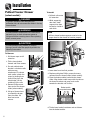
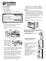
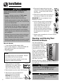
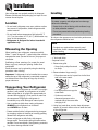
Installation
Your refrigerator was packed carefully for shipment.
Remove and discard shelf packaging and tape. Do not
remove the serial plate.
Location
• Do not install refrigerator near oven, radiator or other
heat source. If not possible, shield refrigerator with
cabinet material.
• Do not install where temperature falls below 55° F
(13° C) or rises above 110° F (43° C). Malfunction may
occur at this temperature.
• Refrigerator is designed for indoor household
application only.
Measuring the Opening
When installing your refrigerator, measure carefully.
Allow 1⁄2” space at top and 1⁄2” space behind the machine
compartment cover (located in the rear) for proper air
circulation.
Subflooring or floor coverings (i.e. carpet, tile, wood
floors, rugs) may make your opening smaller than
anticipated.
Some clearance may be gained by using the leveling
procedure under Leveling.
Important: If refrigerator is to be installed into a recess
where the top of the refrigerator is completely covered,
use distance from floor to top of hinge cap to verify
proper clearance.
Leveling
CAUTION
To protect property and refrigerator from damage,
observe the following:
• Protect vinyl or other flooring with cardboard, rugs,
or other protective material.
• Do not use power tools when performing leveling
procedure.
To enhance the appearance and maintain performance,
the refrigerator should be level.
Note
• Complete any required door reversal, panel
installation and/or a water supply connection,
before leveling.
Materials Needed:
• 3⁄8” hex head driver
• Carpenter’s level
1. Remove toe grille.
• Grasp firmly and pull outward
to unclip.
2. Remove bottom hinge cover(s).
• Place the eraser end of a pencil or similar blunt
tool in the cover notch.
Notch
Location
Transporting Your Refrigerator
• NEVER transport refrigerator on its side. If an upright
position is not possible, lay refrigerator on its back.
Allow refrigerator to sit upright for approximately 30
minutes before plugging it in to assure oil returns to
the compressor. Plugging the refrigerator in
immediately may cause damage to internal parts.
• Use an appliance dolly when moving refrigerator.
ALWAYS truck refrigerator from its side or
back–NEVER from its front.
• Use slight pressure to pry the
cover loose.
• Continue to maintain
downward pressure to the
notched side of the cover while
swinging it off.
3. Using hex head driver, turn the front adjustment
screws (A) on each side to raise or lower the front
of the refrigerator.
• Protect outside finish of refrigerator during transport
by wrapping cabinet in blankets or inserting padding
between the refrigerator and dolly.
3
• Secure refrigerator to dolly firmly with straps or
bungee cords. Thread straps through handles when
possible. Do not overtighten. Overtightening restraints
may dent or damage outside finish.
A B
C
BA
C
Installation
CAUTION
Note
• Some models only have adjustment screws “A.”
To avoid damage to walls and flooring, protect vinyl
or other flooring with cardboard, rugs or other
protective material.
4. Using the hex head driver, turn each of these
adjustment screws (B) to raise or lower the rear of
the refrigerator.
1. Unplug power cord from power source.
5. Using the carpenter’s level, make sure front of
refrigerator is 1⁄4” (6 mm) or 1⁄2 bubble higher than
back of refrigerator and that the refrigerator is level
from side to side.
6. Turn stabilizing legs (C) clockwise until firmly
against floor.
7. Turn adjustment screws (A) counterclockwise to
allow the full weight of the refrigerator to rest on
the stabilizing legs.
8. Replace hinge cover(s).
• Position cover into the outer edge of the hinge.
• Swing the cover toward the cabinet and snap it
into place.
9. Replace the toe grille.
Note
• For proper reinstallation, ensure the “top” marking
on the interior of the toe grille is oriented correctly.
• Align the toe grille mounting clips with the lower
cabinet slots.
• Push the toe grille firmly until it snaps into place.
Door and Drawer Removal
Some installations require door/drawer removal to
transport the refrigerator to its final location.
WARNING
To avoid electrical shock which can cause severe
personal injury or death, observe the following:
• Disconnect power to refrigerator before removing
doors or drawer. Connect power only after
replacing doors or drawer.
2. Remove toe grille and bottom hinge
cover(s) (see page 3).
3. Remove top hinge cover from
refrigerator door by removing Phillips
screw and retain screw and cover for
later use.
4. Unscrew 5⁄16” hex head screws from
top hinge to remove hinge and retain
all screws for later use.
5. Lift right side refrigerator door from
center hinge pin. Remove door
closure from center hinge pin on
the right side and retain for later
use.
6. Disconnect wire harness on top
of left side refrigerator door top
hinge.
right
side
door
closure
Release two-pin connector by
pressing junction point with a
flat blade screwdriver or
fingernail.
Green ground wire remains
attached to the hinge.
7. Unscrew 5⁄16” hex head screws from
top hinge to remove hinge and retain
for later use.
Lift left side refrigerator door, along
with top hinge, from center hinge pin.
Remove center hinge pin with a 5⁄16”
hex head driver and retain hinge pin
for later use.
8. Remove Phillips screws to remove
right and left hinges and retain all
screws for later use.
9. Remove both stabilizing brackets
with 3⁄8” hex head driver and retain
screws for later use.
4
Installation
Pullout Freezer Drawer
To Install:
1. Pull both rails out to
full extension.
(select models)
DANGER
To prevent accidental child entrapment or
suffocation risk, do not remove the divider in the top
freezer basket.
2. While supporting
door front, hook
supports into slots
located on inside of
each slide.
WARNING
To avoid electrical shock which can cause severe
personal injury or death, disconnect power to
refrigerator before removing doors. After replacing
doors, connect power.
Note
• All four drawer bracket supports must be in the
proper slots for the drawer to function properly.
CAUTION
To avoid possible injury, product, or property
damage, you will need two people to perform the
following instructions.
To Remove:
1. Pull drawer open to full
extension.
2. Tilt the lower basket
forward and lift to remove.
3. On each white drawer
bracket is a basket cradle
with two snap
attachments. To release
each cradle, unlatch the
snaps by pushing them
inward, away from the
side bracket. Lift the
cradles off of the rails.
4. Remove Phillips screw
from each of the drawer
slides (select models).
3. Lower door front into final position.
4. Replace and tighten Phillips screws that were
removed from the drawer slides (select models).
5. Place the basket cradles back onto the drawer
slides. Align basket cradle snaps with the slots on
the drawer brackets and press each cradle
towards the bracket until it clicks.
Basket cradle
snap attachments
5. Lift top of drawer front
to unhook the drawer
from the slides. Lift
door front out to
remove.
6. Tilt the lower basket front down and set it down
into the basket cradles.
5
Installation
Door Reinstallation
1. Install hinge assemblies:
3. Ensure the handle clips are
positioned slightly above the
door tabs.
Handle
Clip
• Install center hinge with Phillips screws.
2. Place hinge side of refrigerator door on center
hinge pin.
• Install top hinge with 5⁄16” hex head
screws.
Door
Tab
4. Rotate the handle so that the
handle is flat against the door.
3. While holding refrigerator door
upright, tighten down top hinge
with 5⁄16” hex head driver.
4. Reconnect two-pin connector.
5. Replace top hinge covers.
5. Push the handle down against the
upper door tab just enough to
allow it to hang unsupported.
Handles
If not installed, the handle is located in the interior of
the fresh food section or attached to the back of your
refrigerator.
Remove and discard handle packaging and tape.
Front Mount Handle
Materials Needed:
• Gloves to protect hands
• Phillips screwdriver
• Plastic door removal card (or 1⁄32” thick plastic card),
retain the card
Attach Extensions to Handle:
1. Align handle and
extension as shown.
2. Place extension in
handle opening.
3. Apply slight pressure
to both sides of the extension piece.
4. Slide extension until it stops on inside edge of
handle.
6. Align bottom of handle with lower
door tab. Press upper handle end to
door surface and firmly grasp lower
end of handle. Gently slide handle
upward until bottom of handle
settles on door surface, then
reverse direction, sliding downward
to almost engaging tab with clip.
7. Grasp the handle firmly and slide
down until it clicks. The audible
click indicates fastening clips are
securely interlocked.
To Remove:
1. Flex the handle away from the door
panel. Simultaneously place door
handle removal card underneath
the base of the lower handle. Insert
the card to the line or until it stops.
To Install:
1. The handles are to be oriented
as shown.
2. Align front mount door handle
clip with the door tabs.
2. Grasp the lower part of the handle
firmly and lift to remove.
6
Installation
engagement. Then firmly slide the handle to the
right until it clicks. The audible “click” indicates
that the fastening clips are securely interlocked.
Freezer Handle
Materials Needed:
• Gloves to protect hands.
• Phillips screwdriver.
• Plastic handle removal card (or 1⁄32” thick plastic
card). Retain the card.
Notes
• There is a slight curve to
the freezer handle.
To Remove:
1. At the right end, flex the handle base away from
the surface of the freezer drawer. Simultaneously
slide the door handle removal card that came with
your refrigerator under the right side base of the
handle. Slide the card to the line indication or until
it stops, which will be approximately 11⁄2”.
2. With both hands, firmly grasp the handle towards
the right base.
• For proper installation, be
sure handle is oriented as
shown.
3. Slide towards the left, lift and remove from the
surface.
To Install:
1. Align door handle clips slightly to the left of the
tabs attached to the freezer door.
2. Rotate the handle so the left base is flat against
the door.
Handle
Clip
Door
Tab
Handle
Base
3. Push the left handle
base against the left
door tab and slightly
to the right, just
enough to allow it to
hang unsupported.
4. While firmly supporting the left handle base against
the door, align the right base of the handle with the
right tabs that are attached to the door.
5. Now, while firmly holding the handle at the left and
right bases, gently slide the handle towards the
right until the right base settles in. The handle
should now be flat against the face of the freezer
door at both the left and right bases.
7
6. With hands still firmly keeping the handle flat
against the freezer door, you may have to reverse
directions momentarily to assure clip/tab
Installing Front-Mounted Handles for
Stainless Steel Doors
1. Loosen lower door clip on door with
a phillips screwdriver.
2. Locate predrilled hole at base of
handle, and fit hollow end of
handle over lower door clip.
3. Fit other end of handle over upper
door clip and slide up as far as
possible.
NOTE: If top of handle does not fit
over top clip, loosen lower clip
further until fit can be
accomplished.
4. Insert phillips screwdriver into
predrilled hole at base of handle
to tighten screw. Insert plastic
button plug into hole.
5. Repeat above steps to install
other handle.
Installation
Removing Front-Mounted Handles for
Stainless Steel Doors
Removing Front-Mounted Handles for
Stainless Steel Freezer Door
1. Remove plastic button plug at base
of handle with a very small flat-blade
screwdriver.
1. Remove right side plastic button
plugs at each end of handle
with a very small flat-blade
screwdriver.
• Insert phillips screwdriver into
predrilled hole to remove screw.
2. Slide handle down and remove
from door clip.
• Insert phillips screwdriver
into predrilled hole to remove
screw.
2. Slide handle right and
remove from door clip.
3. Repeat above steps to remove
other handle.
Installing Front-Mounted Handles for
Stainless Steel Freezer Door
1. Loosen lower door clip on door
with a phillips screwdriver
Connecting the Water Supply
WARNING
To reduce the risk of injury or death, follow
basic precautions, including the following:
2. Locate predrilled hole at base of
handle, and fit hollow end of
handle over left door clip.
• Read all instructions before installing ice maker.
• Do not attempt installation if instructions are not
understood or if they are beyond personal skill
level.
• Observe all local codes and ordinances.
3. Fit other end of handle over
left door clip and slide left as
far as possible.
NOTE: If end of handle does
not fit over left clip, loosen
right clip further until fit can
be accomplished.
4. Insert phillips screwdriver
into predrilled hole at end of
handle to tighten screw.
Insert plastic button plug into
hole.
• Do not service ice maker unless specifically
recommended in Use & Care Guide or published
user-repair instructions.
• Disconnect power to refrigerator before installing
ice maker.
• Water damage due to an improper water
connection may cause mold/mildew growth. Clean
up spills or leakage immediately!
cont.
8
Installation
4. Place end of copper tubing into water
valve inlet port. Shape tubing slightly. Do
not kink – so that tubing feeds straight
into inlet port.
CAUTION
To avoid property damage or possible injury,
follow basic precautions, including the
following:
5. Slide brass nut over sleeve and screw nut
into inlet port. Tighten nut with wrench.
• Consult a plumber to connect 1⁄4” O.D. copper
tubing to household plumbing to assure
compliance with local codes and ordinances.
• Confirm water pressure to water valve is between
35 and 100 pounds per square inch, 20 pounds per
square inch without filter.
• Do not use a self-piercing, or 3⁄16” saddle valve. Both
reduce water flow and can become clogged over
time, and may cause leaks if repair is attempted.
• Tighten nuts by hand to prevent cross threading.
Finish tightening nuts with pliers and wrenches. Do
not overtighten.
• Wait two to three hours before placing refrigerator
into final position to check and correct any water
leaks. Recheck for leaks after 24 hours.
• Verify the copper tubing under the sleeve is smooth
and free from defects. Do not reuse an old sleeve.
Materials Needed:
• 1⁄4” outer diameter flexible copper tubing
• Shut-off valve (requires a 1⁄4” hole to be drilled into
water supply line before valve attachment)
• Adjustable wrench
• 1⁄4” hex nut driver
Notes
• Use copper tubing only for installation. Plastic is
less durable and can cause damage.
• Add 8’ to tubing length needed to reach water
supply for creation of service loop.
1. Create service loop with copper
tubing (minimum 2’ diameter).
Avoid kinks in the copper tubing
when bending it into a service
loop. Do not use plastic tubing.
2’ diameter
minimum
9
6. Pull on tubing to confirm connection is
secure. Connect tubing to frame with
C
water tubing clamp (C) and turn on
water supply. Check for leaks and
correct if necessary. Continue to
observe the water supply connection
for two to three hours prior to moving
the refrigerator to its permanent
location.
7. Monitor water connection for 24 hours. Correct
leaks, if necessary.
Opening and Closing Your
Fresh Food Doors
Your new refrigerator is
uniquely designed with two
fresh food doors. Either door
can be opened or closed
independently of one another.
hinged
seal
There is a vertically-hinged
section on the left fresh food
door. When the left door is
closed, the hinged section
automatically forms a seal
between the two doors when
both doors are closed.
When the left door is opened,
the hinged seal automatically folds inward so that it is
out of the way.
WARNING
2. Remove plastic cap from water valve inlet port.
3. Place brass nut (A) and sleeve (B) on
copper tube end as illustrated.
Reminder: Do not use an old
sleeve. The nut and sleeve are
provided in the use and care packet.
IMPORTANT: Do not overtighten. Cross
threading may occur.
A
B
To avoid electrical shock which can cause severe
personal injury or death, DO NOT attempt to
remove the hinged seal from the fresh food
section.
CAUTION
To avoid possible product damage, ALWAYS verify
that the hinged seal is folded against the edge of
the door prior to closing.