1
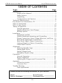
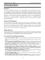
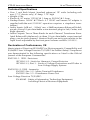
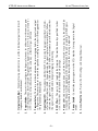
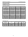
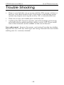
XTD-33
INSTRUCTION
MANUAL
Digital Crossover
Quality Cinema Products
Ultra★Stereo Labs, Inc. • 181 Bonetti Drive
San Luis Obispo, CA 93401
Telephone 805.549.0161 • e-mail [email protected]
XTD-33 INSTRUCTION MANUAL
ULTRA★STEREO LABS, INC.
One Year Limited Warranty
★★★★★
Ultra★Stereo Labs, Inc. warrants that each product manufactured by it will be free from defects in material and workmanship
under normal usage for a period of one (1) year after its purchase
new from an authorized dealer. Our obligation under this
warranty is limited to repairing or replacing any product or
component which we are satisfied does not conform with the
foregoing warranty and which is returned to our factory, freight
paid, or serviced by one of our authorized contractors. The
foregoing warranty is exclusive and in lieu of all other warranties, whether expressed or implied. Such warranty shall not
apply to any product or component (A) repaired or altered by
anyone other than Ultra★Stereo Labs or an authorized service
contractor; (B) tampered with or altered in any way or subjected
to misuse, negligence or accident or (C) which has been improperly connected, installed or adjusted other than in accordance
with Ultra★Stereo Labs instruction.
Quality Cinema Products
© 2000 All Rights Reserved
Ultra★Stereo Labs, Inc.
181 Bonetti Drive
San Luis Obispo, CA, 93401USA.
Telephone 805.549.0161
FAX 805.549.0163
e-mail: [email protected]
0100
-2-
XTD-33 INSTRUCTION MANUAL
ULTRA★STEREO LABS, INC.
Table of Contents
Topic
Page
Introduction ............................................................................. 5
Scope of this Manual ...................................................... 5
Safety Notices ................................................................ 5
Unpacking ..................................................................... 6
Configurations and Options ........................................... 6
Technical Specifications .......................................................... 7
Declaration of Conformance, CE.............................................. 7
XTD-33 Front Panel ................................................................. 8
XTD-33 Rear Panel ................................................................ 10
Theory of operation ............................................................... 12
Normal operation ......................................................... 12
Speaker Protection (Anti-Thump) .................................. 13
Backup System ............................................................. 13
Installation ............................................................................. 14
Equipment needed ....................................................... 14
System Hardware Mounting and Grounding ................ 14
Power Connection, Main Voltage Selection, and Fuse .. 15
Rear Panel Signal Input Connections ............................ 16
Rear Panel Signal Output Connections ......................... 17
Optional Signal to Chassis Grounding .......................... 17
Front Panel Controls ..................................................... 18
Alignment .............................................................................. 19
Selecting Speaker Type ................................................ 19
Setting Input levels ....................................................... 19
Setting Output levels .................................................... 20
Emergency Bypass setup .............................................. 20
Operation .............................................................................. 21
Normal Operation ........................................................ 21
Bypass Operation ......................................................... 21
Updating the Program and Crossover Files ................... 21
Appendix ............................................................................... 22
Connector pinouts ........................................................ 22
Crossover List ............................................................... 22
Trouble Shooting ................................................................... 23
Fuse replacement ......................................................... 23
Please record the following information for your records:
Model: ___________________ Serial Number: ___________
Date of Purchase: __________ Purchased from: __________
-3-
XTD-33 INSTRUCTION MANUAL
ULTRA★STEREO LABS, INC.
-4-
XTD-33 INSTRUCTION MANUAL
ULTRA★STEREO LABS, INC.
Introduction
General
The XTD is designed as an easy-to-set-up, high performance digital crossover.
It is designed to match the most commonly used speaker types currently
produced by several manufacturers. The 96kHz sample rate, 24-bit resolution and flexible firmware assures it will meet the demands of future speaker
designs. It may be used with other equipment, such as room equalization
equalizers, to isolate specific functions and provide a complete audio
processing system. The XTD is compatible with all commercially available
sound processors.
Scope of this Manual
This manual is to aid in the installation and operation of the XTD-33 Digital
Crossover. Because the XTD is designed for use with specific speaker systems,
there may be situations that the XTD cannot correct (e.g., a room with
excessive acoustic absorption or a power amplifier without sufficient power).
Please contact USL if you have any questions
Safety Notices
Review the following safety precautions to avoid injury and prevent damage
to this product. To avoid potential risk, use this product only as specified and
only for the purpose described in the instruction manual.
To Avoid Fire and Personal Injury:
• Use Correct Power Cable. Use only the power cable provided. Ensure
that the AC power outlet is located near the product and is easily accessible.
• Use a Correctly Grounded Power Source. The Power Supply earth ground
is established through the ground conductor in the power cable. To avoid
the potential of electric shock, the ground conductor must be correct.
• Observe Source Ratings. To avoid risk of fire or electric shock, the power
source must be 110 - 120 VAC, 60Hz or 220 - 240 VAC, 50 Hz.
• Do Not Operate this Product with Any Enclosures Opened or Removed.
• Avoid Exposed Circuitry. Do not attempt to open the Power Supply because its safety certification would be invalidated.
• Do Not Operate with Suspected Failures. If you suspect there is damage
or malfunction with this product, call the factory.
• Do Not Attempt Repair. Only a trained factory service person is authorized to repair this product.
• Do Not Operate this Product Near Heat Sources. This product should not
be located near heat sources such as radiators, heat registers, or stoves.
-5-
XTD-33 INSTRUCTION MANUAL
ULTRA★STEREO LABS, INC.
• Provide Proper Ventilation. The operating temperature should be between
0º C and 50º C. The humidity should be <90% at 40º C or below and
<60% at 41º C to 50º C. The cooling method is by convection.
• Keep Product Surfaces Clean and Dry. Disconnect the power cable from
the power source before cleaning. Do not use liquid cleaners or aerosol
cleaners. Use a damp cloth for cleaning.
• Do Not Push Objects Into Opening of this Product. Never insert objects
into the product through openings.
• Do Not Operate In Wet or Damp Conditions.
• Do Not Operate In an Explosive Atmosphere.
• Prevent the Spilling of Liquids onto the System Components.
• Inspect the power cable and all cables prior to use. Confirm that the
power cable and other interconnecting cables are free from damage.
Safety Standard
The EN 60065 standard specifies safety design requirements that reduce or
eliminate the risk of personal injury to both the product user and service
personnel. This product is designed and tested to meet the standards of the
International Electrotechnical Commission (IEC) European Norm (EN) 60065
(The Standard for Information Technology Equipment Including Electrical
Business Equipment).
Unpacking
The shipping box contains:
This Owner’s Manual
XTD-33 Screw Terminal Plugs (4)
Power Cord IEC type for the country specified when ordered
Backup Power Transformer (Stepdown Transformer also required for the
Backup Transformer in 230 VAC systems)
Configurations
The XTD has three available channels which may be configured with two or
three bands for each channel simultaneously. Inputs and outputs may
individually be configured as balanced or unbalanced. When an input or
output is used in the unbalanced mode, the negative signal should be
connected to signal ground (“E”).
Options
If the standard speaker selections do not match your configuration, USL may
be able to provide you with a customized program to optimize your audio.
-6-
XTD-33 INSTRUCTION MANUAL
ULTRA★STEREO LABS, INC.
Technical Specifications
• Size: 1 unit Rack Mount (standard reference) 19" wide (including rack
ears; 17.5" chassis only), 8" deep, 1.75" high
• Weight: 8 lbs.
• Electrical: AC mains 115VAC @ 1 Amp or 230VAC @ 1 Amp
• Backup Power: 16VAC @ 750mA. A 115VAC wall mount AC adapter is
supplied with the unit. (230VAC operation requires a stepdown transformer.)
• Audio Inputs: 0dB ref. - 300mV rms, +26dB maximum Balanced/Unbalanced via one 10-pin detachable screw terminal plug for Left, Center, and
Right channels
• Audio Outputs: Two or Three Bands for each Channel. Transformer Simulated Balanced/Unbalanced via three 10-pin detachable screw terminal
plugs, one for each channel. Nominal levels are unity gain relative to the
input levels adjustable by the front panel volume controls (0-100%).
Declaration of Conformance, CE
Meets intent of Directive 89/336/EEC for Electromagnetic Compatibility and
93/68/EEC Low-Voltage Directive 73/23/EEC for Product Safety. Compliance
was demonstrated to the following specifications as listed in the Official
Journal of the European Communities:
EN55103-1: 1999 - Emissions:
IEC1000-3-2 - Limits for Harmonic Current Emission
IEC1000-3-3, Part 3 - Limits of Voltage Fluctuations and Flicker in
Low Voltage Supply Systems
EN550103-2: 1999 - Immunity:
EN55013 Sec 3.2 - Mains Terminal Disturbance
EN55013 Sec 3.5 - Disturbance Power Test
Low Voltage Directive 73/23/EEC:
EN 60065 - Safety of Information Technology Equipment,
Including Electrical Business Equipment
-7-
THREE CHANNEL, THREE WAY
DIGITAL CROSSOVER
XTD-33
Ll
Cl
1
Cm Ch
Rl
Rm Rh
34 56
3
34 56
PROGRAM
SELECT
78 9A
2
DPU04
BYPASS
MODE
F 012
ON
OUTPUT LEVEL ADJUST
Lm Lh
B C DE
-8-
B C DE
F 012
8
LEFT
Yellow = 0Db Ref
CENTER
RIGHT
4
SIGNAL INPUT
5
RS-232
XTD-33 Front Panel
6
POWER
7
ON
Quality Cinema Products
XTD-33 INSTRUCTION MANUAL
ULTRA★STEREO LABS, INC.
78 9A
-9-
8. Access Panel Cover - Protects the XTD settings and keeps the dust out.
7. Power Switch - Controls the primary power to the XTD. Must be On to operate in the Digital
Mode.
6. Power LED - Under normal conditions, with the Power Switch On and no faults, the LED will be
Green and the unit will be operating in the Digital Mode. If the unit is operating in the Bypass
(analog) Mode, the LED will be Red and may indicate that servicing is required.
5. RS-232 Port - This port is used to update the firmware. This must be done by a qualified technician. Instructions are included in the update package.
4. Signal Input LED - These indicate whether the XTD is receiving the proper signal level. Off indicates the level is below -54 dB. Green indicates the signal is present at normal levels. Yellow
indicates the signal is within ± 0.5dB of the 0dB (300mV rms) reference point. Red indicates that
the signal is over +23dB and in danger of clipping or distorting.
3. Program Select - These two switches determine the processing applied to the signals and output
configuration. These must be set to match the speakers according to the chart in the Appendix or
the speakers may be damaged.
2. Bypass Mode - These switches configure the bypass electronics for either two-or-three-way operation (should always be set to match the speaker configuration). Up (or ON) is two-way; Down (or
OFF) is three-way. All switches must be set the same way - either all Up or all Down.
1. Output Level Adjust - Nine multi-turn potentiometers to set the individual output levels for each
frequency band in each channel.
XTD-33 INSTRUCTION MANUAL
ULTRA★STEREO LABS, INC.
1
2
115V
Main Power
115/230 VAC
50/60Hz, 40VA
3
FUSE 1A 250V
Emergency
Bypass
Power
16VAC
500MA
WARNING: TO REDUCE THE RISK OF FIRE
OR ELECTRIC SHOCK, DO NOT EXPOSE
THIS APPLIANCE TO RAIN OR MOISTURE.
DO NOT REMOVE COVER. NO USER
SERVICABLE PARTS INSIDE. REFER
SERVICING TO QUALIFIED PERSONELL.
FOR CONTINUED PROTECTION AGAINS
FIRE OR SHOCK HAZARD, REPLACE ONLY
WITH THE SAME FUSE TYPE AND RATING.
XTD-33
DIGITAL CROSSOVER
RIGHT
4
CENTER
INPUTS
LEFT
HIGH
5
MID
LOW
RIGHT CHANNEL OUTPUTS
HIGH
6
MID
LOW
CENTER CHANNEL OUTPUTS
XTD-33 Rear Panel
HIGH
7
MID
LOW
LEFT CHANNEL OUTPUTS
XTD-33 INSTRUCTION MANUAL
ULTRA★STEREO LABS, INC.
230V
- 10 -
- 11 -
7) Left Channel Outputs - Provides the signal outputs from the XTD in two or three bands as determined by the Program Select and Bypass Mode switches on the front panel. Balanced or Unbalanced signals may be used. In Unbalanced mode, the negative signal should be connected to
signal ground (“E”).
6) Center Channel Outputs - Provides the signal outputs from the XTD in two or three bands as
determined by the Program Select and Bypass Mode switches on the front panel. Balanced or
Unbalanced signals may be used. In Unbalanced mode, the negative signal should be connected
to signal ground (“E”).
5) Right Channel Outputs - Provides the signal outputs from the XTD in two or three bands as
determined by the Program Select and Bypass Mode switches on the front panel. Balanced or
Unbalanced signals may be used. In Unbalanced mode, the negative signal should be connected
to signal ground (“E”).
4) Inputs - Accepts the Left, Center, and Right signals from the Cinema Processor or other audio
source. Balanced or Unbalanced signals may be used. In Unbalanced mode, the negative signal
input should be connected to audio source ground.
3) Emergency Bypass Power - Connect the furnished external power supply here.
2) Fuse Holder - Determines AC Mains configuration. Must be set to match the local AC Mains
voltage or the XTD may be damaged or not operate properly.
1) IEC Power inlet - Accepts a standard IEC cord
XTD-33 INSTRUCTION MANUAL
ULTRA★STEREO LABS, INC.
XTD-33 INSTRUCTION MANUAL
Input
Buffers
A/D
Converters
ULTRA★STEREO LABS, INC.
Digital
Filters
D/A
Converters
Volume
Controls
DSP
Program
Select
Analog
Filters
Bypass
Circuitry
2 or 3
Way
XTD-33 Block Diagram
- 12 -
Bypass
Control
Output
Buffers
XTD-33 INSTRUCTION MANUAL
ULTRA★STEREO LABS, INC.
Theory of operation
Normal operation
Under normal operation, the input signal is conditioned and converted from
an analog waveform to digital information at a sample rate of 96 kHz (twice
that of a normal music CD). The digital data is then processed in a single chip
Digital Signal Processor (DSP) which analyzes the waveform, breaks the
signal into the appropriate audio bands and impresses the desired acoustic
curve onto the information. These acoustic curves are shaped to match a
manufacturer’s specific speaker response selected by the switches on the
XTD front panel. The data is then converted back to analog waveforms and
passed through individual volume controls to the output Transformer Simulators. The Simulators provide a balanced line output which may also be used
in an unbalanced configuration by shorting the unused output to ground
Speaker Protection (Anti-Thump)
To minimize damage to the speakers, an anti-thump system shorts the
balanced line outputs together during power on or off. However, to assure the
best protection, it is recommended that the power amplifiers always be the
last to be turned on and the first to be turned off.
Backup System
It is USL’s policy to try to provide a “safety net” when possible. The backup
system here allows the XTD to continue to operate if the primary XTD power
supply fails or there is a malfunction in the Digital Signal Processing part of
the unit. The Backup Power Transformer constantly feeds into the analog
portion of the circuitry, should the primary supply fail, the backup will take
its place and the Power Supply LED will change from green to red. The Input
signals will be rerouted around the digital portion of the circuitry and into a
conventional analog crossover. This crossover can be configured as either a
two-or-three-band type by means of front panel switches. The signals are then
directed to the volume controls as noted in the Normal Operation above.
These crossovers are of a generic 12dB per octave type but would not be
optimized for all models of speakers. The crossover points are located at
approximately 500 Hz and 1800 Hz in the three-band mode and 500 Hz in
the two-band mode. Should the digital processing malfunction for some
unforeseen reason, turning the power switch off will activate the bypass
system. Obviously, the Backup System is intended for temporary use until the
unit can be restored to proper operation.
- 13 -
XTD-33 INSTRUCTION MANUAL
ULTRA★STEREO LABS, INC.
Installation
Equipment needed
Small Phillips screwdriver
Straight blade screw driver with 1/8" wide tip (or slightly smaller) or
alignment tool
Wire strippers
Audio Cable - (determine your configuration first)
For Balanced and Unbalanced Lines - Individual two-conductor
with shield or
three pairs cable with individual shield per pair
Two AC mains Outlets (one for mains power, one for the backup
power adapter)
System Hardware Mounting and Grounding
Rack mount the XTD with bolts (not supplied) appropriate to your setup. To
assure good chassis grounding, use a star washer between at least one bolt
head and XTD.
Power Connection, Main Voltage Selection, and Fuse
Determine whether 115 or 230 VAC operation.
For 115VAC Operation:
(A 1 Amp fuse has been installed in the fuse holder at the factory.)
1) Verify that the fuse holder is installed into the IEC connector housing
so that the “115” is correctly oriented and readable.
2) Insert the IEC power cord with the appropriate plug into the IEC
connector and the AC mains source
3) Emergency Power Supply - Plug the power adapter16VAC plug into
the jack on the rear of the XTD.
4) Insert the adapter into the AC mains source
- 14 -
XTD-33 INSTRUCTION MANUAL
ULTRA★STEREO LABS, INC.
For 230VAC Operation:
1) Insert/verify a 1 amp fuse is in the fuse holder.
2) Insert the fuse holder into the IEC connector housing so that the “230”
is correctly oriented and readable.
3) Insert the IEC power cord with the “Euro” plug into the IEC connector
and the AC mains source
4) Emergency Power Supply - Plug the power adapter16VAC plug into
the jack on the rear of the XTD.
5) Plug the power adapter into a stepdown transformer.
6) Insert the transformer/adapter into the AC main source.
FUSE 1A 250V
230V
115V
Emergency
Bypass
Power
16VAC
500MA
Main Power
115/230 VAC
50/60Hz, 40VA
XTD-33 Power Connection
- 15 -
XTD-33 INSTRUCTION MANUAL
ULTRA★STEREO LABS, INC.
Rear Panel Signal Input Connections
Balanced Inputs
The XTD has balanced inputs for the cleanest possible signal. For each
channel, connect the audio source positive output to the positive input of the
XTD. Connect the audio source negative output to the negative input of the
XTD. Connect the cable shield only to the XTD signal ground (“E”) to
minimize hum due to ground loops.
INPUTS
INPUTS
RIGHT
CENTER
RIGHT
LEFT
CENTER
LEFT
GND
Balanced Input
Unbalanced Input
Unbalanced Inputs
For each channel, connect the audio source positive output to the positive
input of the XTD. Connect the audio source negative output to the negative
input of the XTD. Connect the cable shield only to the XTD signal ground (“E”)
to minimize hum due to ground loops.
- 16 -
XTD-33 INSTRUCTION MANUAL
ULTRA★STEREO LABS, INC.
Rear Panel Signal Output Connections
Three-Way Crossover Connection - use all three output bands: Low, Mid, High
Two-Way Crossover Connection - use only Low and High bands
Balanced Outputs
For each band in each channel, connect the XTD positive output to the
positive input of the Amplifier. Connect the XTD negative output to the
negative input of the Amplifier. Connect the cable shield only to the Amplifier
signal ground to minimize hum due to ground loops
LEFT CHANNEL OUTPUTS
HIGH
+
GND
MID
LEFT CHANNEL OUTPUTS
LOW
HIGH
NO SHIELD
CONNECTION
Channel 1
Channel 1
MID
LOW
+
GND
Unbalanced Output
Balanced Output
Unbalanced Outputs
The outputs of the XTD use a solid state transformer simulator. BOTH
POSITIVE AND NEGATIVE OUTPUTS MUST BE CONNECTED SOMEWHERE. (If your Amplifier does not have balanced inputs, the XTD negative
output needs to be connected to the XTD signal ground [“E”] by a short piece
of wire.) For each band in each channel, connect the XTD positive output to
the positive input of the Amplifier. Connect the XTD negative output to the
signal ground output (“E”) with a short piece of wire. Connect the cable shield
only to the Amplifier to minimize hum due to ground loops
Optional Signal to Chassis Grounding
If you wish to connect the Signal Ground (“E”) to the Chassis Ground, install
a jumper between the two left terminal block pins on only one of the terminal
blocks (any terminal block).
Optional Chassis Grounding
- 17 -
XTD-33 INSTRUCTION MANUAL
ULTRA★STEREO LABS, INC.
Front Panel Controls
• The only control designed to always be available is the Power Switch. In
the ON position power is supplied via the AC Mains, the Power LED will be
Green, the Digital Crossover section of the XTD is enabled, and the Analog
crossover is disabled. When the Power Switch is in the OFF position, power
is supplied by the Emergency Bypass Supply, the Power LED will be Red, the
Digital Crossover section of the XTD is disabled, and the Analog crossover is
enabled.
• Behind the access panel are the Digital Configuration switches, Analog
Crossover Mode selector switches, and the volume controls for the nine
outputs. Digital Configuration switches allow for 100 different speaker
configurations as identified in the Appendix.
Analog Crossover Mode selector switches allow the emergency bypass
circuitry to be configured for two-way or three-way systems and should be set
to match the Digital Configuration. Up (or On) is two-way; Down (or Off) is
three-way.
The Volume Controls allow the nine output signal levels to be adjusted. These
work in either the Normal or Bypass modes and adjustment should not be
needed when switching between the two.
- 18 -
XTD-33 INSTRUCTION MANUAL
ULTRA★STEREO LABS, INC.
Alignment
Rm Rh
BYPASS
MODE
PROGRAM
SELECT
34 56
78 9A
78 9A
DPU04
34 56
F 012
Rl
F 012
Cm Ch
ON
Cl
B C DE
Lm Lh
B C DE
OUTPUT LEVEL ADJUST
Ll
Selecting Speaker Type
CAUTION: Incorrectly setting the Speaker Type selector switches can
damage speakers. Verify settings before activating amplifiers.
1) Turn the amplifiers off.
2) Turn the XTD off.
3) Use the chart in the Appendix to determine the setting that matches
your speakers. If your speakers are not listed, please contact USL.
4) Use a small screwdriver to set the rotary switches to the matching
setting.
5) Set the Bypass Mode switches to match the speaker configuration,
two-or-three-way. Up (or ON) is two-way; Down (or OFF) is threeway. All switches must be set the same way - either all Up or all
Down.
6) Turn the XTD Volume pots fully counter-clockwise.
7) Set the Cinema Processor equalizer (or room equalizer) to “flat” (no
gain or attenuation) for all channels.
Setting Input levels
1) Turn on the XTD (but not the amplifiers).
2) Use a Pink Noise generator or other 0dB reference signal in the
Cinema Processor.
3) Note: The XTD is designed to accept signal levels up to +26dB
(6.25V rms) with a 0dB reference of 300 mV rms.
- 19 -
XTD-33 INSTRUCTION MANUAL
ULTRA★STEREO LABS, INC.
4) Adjust the output level of the Cinema Processor Left Output Level
Control until the Channel Signal Level LED on the XTD just turns
yellow (The Signal Level LEDs will be Green ± 0.5dB above or below
0dB, Yellow within ± 0.5dB of 0dB, and Red when above +23dB and
in danger of clipping)
5) Repeat for the Center and Right Channels.
Setting Output levels
Note: The XTD Volume Controls are factory-set fully counterclockwise (off
or zero) for shipping to prevent accidental damage to your speakers.
1) Set up a Sound Pressure Meter, set to “C” weighting, and a Spectrum
Analyzer in the audience area.
2) Turn on the Left Channel Low Frequency Amplifier. NOTE: The
amplifier volume should be set as it would normally be set. Some
facilities merely set the amplifier volume to maximum (or other
standard level) to facilitate amplifier swap out.
3) Adjust the XTD Left Channel Low Frequency Volume pot until the
Sound Pressure Level is approximately 80dB.
4) Turn off (or down all the way) the Low Frequency Amplifier.
5) If you are using a two-way system, skip the mid range adjustment and
leave the mid volume fully counter-clockwise.
6) Turn on the Left Channel Mid Frequency Amplifier.
7) Adjust the XTD Left Channel Mid Frequency Volume pot until the
Sound Pressure Level is approximately 80dB.
8) Turn off (or down all the way) the Mid Frequency Amplifier.
9) Turn on the Left Channel High Frequency Amplifier.
10) Adjust the XTD Left Channel High Frequency Volume pot until the
Sound Pressure Level is approximately 80dB.
11) Turn on the Low, Mid, and High Frequency Amplifiers.
12) Re-adjust Left Channel volumes for the best flat response.
13) Repeat Steps 2-12 for the Center and Right Channels.
14) EQ the room per the Cinema Processor or room equalizer instructions
(without further adjustment of the XTD).
15) Install the Access Panel Cover.
Emergency Bypass setup - None. Refer to Installation section.
- 20 -
XTD-33 INSTRUCTION MANUAL
ULTRA★STEREO LABS, INC.
Operation
Normal Operation
•
Power Switch - During the first 15 seconds after the XTD is turned on,
it will function in the Backup Mode and audio signals will be processed by the analog crossover. Once the system has stabilized and
the firmware programs have been loaded, it will set itself to the
configuration determined by the speaker selection switches.
•
Power LED - Should be green indicating normal operation.
•
Crossover Presets - DO NOT ADJUST WITH THE UNIT ON (see
Alignment Section). The unit only recognizes changes when it is first
turned on. Changing the switches while the power is on may result in
an incompatible configuration that may not be noticed until the next
time the unit is turned on.
•
Signal Level LEDs - The three LEDs indicate the signal levels of the
three input channels to the XTD as shown in the chart below. Note:
0dB = 300mV rms
•
LED Color
Signal Level
Signal Measurement
Off
No Signal
< -54dB
Green
Signal present
-54dB to -0.5dB
Yellow
Reference level
-0.5dB to +0.5dB
Green
Signal present
+0.5dB to +23dB
Red
Clipping
> +23dB
Output Signal Level Adjustment - Should be already set (see the
Alignment Section).
Bypass Operation
•
Backup power - If the primary Power Supply fails the Power LED will
be red, Contact USL. If the digital processing fails (or to check the
processing) turn the Power Switch Off and the unit will go into Bypass
mode, Contact USL
•
Backup Crossover Type (Two-or-Three-Way) - Should be already set
(see Alignment) Up (or On) is two-way; Down (or Off) is three-way.
Updating the Program and Crossover Files
Updating the XTD firmware requires special knowledge and training provided with update package, please contact USL.
Please make note of the firmware version number on the rear of the unit.
- 21 -
XTD-33 INSTRUCTION MANUAL
ULTRA★STEREO LABS, INC.
Appendix
Connector pinouts
Inputs
Right Output
Center Output
Left Output
(Right to Left)
(Right to Left)
(Right to Left)
(Right to Left)
Left Channel +
Low Band +
Low Band +
Low Band +
Left Channel –
Low Band –
Low Band –
Low Band –
Left Channel E
Low Band E
Low Band E
Low Band E
Center Channel +
Mid Band +
Mid Band +
Mid Band +
Center Channel –
Mid Band –
Mid Band –
Mid Band –
Center Channel E
Mid Band E
Mid Band E
Mid Band E
Right Channel +
High Band +
High Band +
High Band +
Right Channel –
High Band –
High Band –
High Band –
Right Channel E
High Band E
High Band E
High Band E
Chassis Gnd
Chassis Gnd
Chassis Gnd
Chassis Gnd
Crossover List
Speaker
Manufacturer
EAW
EV 3 Way
JBL 3 Way
Type
MC4953/MC4973
Variplex
5672/5674
- 22 -
Switch
A
2
3
5
Switch
B
0
0
0
Bypass
Switch
Off
Off
Off
XTD-33 INSTRUCTION MANUAL
ULTRA★STEREO LABS, INC.
Trouble Shooting
•
There is very little that can go wrong with the XTD except a failure of
the fuse. Any other instance such as activation of the backup power
system may require servicing the unit by USL or trained technician.
•
There are no user serviceable parts inside the unit.
•
Updating the XTD firmware requires special knowledge and training
provided with the update package, please contact USL. Please make
note of the firmware version number on the rear of the unit.
Fuse replacement - Remove the power cord and pull out the fuse holder.
Replace the fuse with the same type and rating. Reinstall the fuse holder
making sure it is correctly oriented.
- 23 -
Quality Cinema Products
© 2000 All Rights Reserved
Ultra★Stereo Labs, Inc.
181 Bonetti Drive
San Luis Obispo, CA, 93401USA.
Telephone 805.549.0161
FAX 805.549.0163
e-mail: [email protected]