1
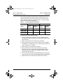
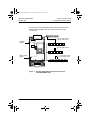
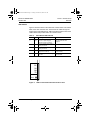
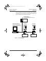
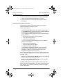
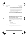
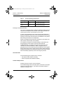
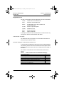
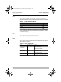
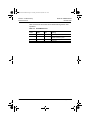
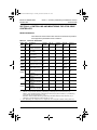
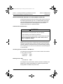
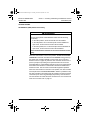
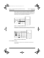
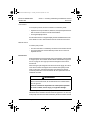
053Cover.fm Page 1 Tuesday, November 28, 2000 9:04 AM
Instruction Bulletin
VVDED397053US
November 2000
Raleigh, NC, USA
ALTIVAR® 58 Adjustable Speed
Drive Controllers
Interbus-S Communication Card
User’s Guide
Retain for Future Use.
053Cover.fm Page 2 Tuesday, November 28, 2000 9:04 AM
DANGER
HAZARDOUS VOLTAGE
•
Read and understand this bulletin in its entirety before installing
or operating ALTIVAR 58 drive controllers. Installation,
adjustment, repair, and maintenance of the drive controllers must
be performed by qualified personnel.
•
Disconnect all power including external control power that may be
present before servicing the drive controller. WAIT THREE
MINUTES for the DC bus capacitors to discharge. Then follow the
DC bus voltage measurement procedure on page 3 to verify that
the DC voltage is less than 45 V. The drive controller LEDs are
not accurate indicators of the absence of DC bus voltage.
•
DO NOT short across DC bus capacitors or touch unshielded
components or terminal strip screw connections with voltage
present.
•
Install and close all covers before applying power or starting and
stopping the drive controller.
•
User is responsible for conforming to all applicable code
requirements with respect to grounding all equipment.
•
Many parts in this drive controller, including printed wiring boards,
operate at line voltage. DO NOT TOUCH. Use only electrically
insulated tools.
Before servicing the drive controller:
•
Disconnect all power.
•
Place a “DO NOT TURN ON” label on the drive controller
disconnect.
•
Lock disconnect in open position.
Electrical shock will result in death or serious injury.
VVDED397053USBook Page i Tuesday, November 28, 2000 9:01 AM
Bulletin No. VVDED397053US
November 2000
Interbus-S Communication Card User’s Guide
Contents
SECTION 1—HARDWARE SETUP . . . . . . . . . . . . . . . . . . . . . . . . . . . . . . . . . . . . . . . . . 1
INTRODUCTION . . . . . . . . . . . . . . . . . . . . . . . . . . . . . . . . . . . . . . . . . . . . . . . . . . . . . . . . 1
REVISION LEVEL . . . . . . . . . . . . . . . . . . . . . . . . . . . . . . . . . . . . . . . . . . . . . . . . . . . . . . . 2
ADDITIONAL DOCUMENTATION . . . . . . . . . . . . . . . . . . . . . . . . . . . . . . . . . . . . . . . . . . . 2
INSPECTING THE OPTION CARD . . . . . . . . . . . . . . . . . . . . . . . . . . . . . . . . . . . . . . . . . . 2
BUS VOLTAGE MEASUREMENT PROCEDURE . . . . . . . . . . . . . . . . . . . . . . . . . . . . . . . 3
INSTALLATION . . . . . . . . . . . . . . . . . . . . . . . . . . . . . . . . . . . . . . . . . . . . . . . . . . . . . . . . . 6
LED STATES . . . . . . . . . . . . . . . . . . . . . . . . . . . . . . . . . . . . . . . . . . . . . . . . . . . . . . . . . . . 7
CONNECTIONS . . . . . . . . . . . . . . . . . . . . . . . . . . . . . . . . . . . . . . . . . . . . . . . . . . . . . . . . . 8
Standard RS-485 Bus . . . . . . . . . . . . . . . . . . . . . . . . . . . . . . . . . . . . . . . . . . . . . . . . . . 9
Cable Routing Practices . . . . . . . . . . . . . . . . . . . . . . . . . . . . . . . . . . . . . . . . . . . . . . . 10
Connection Example . . . . . . . . . . . . . . . . . . . . . . . . . . . . . . . . . . . . . . . . . . . . . . . . . . 11
NOTES . . . . . . . . . . . . . . . . . . . . . . . . . . . . . . . . . . . . . . . . . . . . . . . . . . . . . . . . . . . . . . . 12
SECTION 2—SOFTWARE SETUP . . . . . . . . . . . . . . . . . . . . . . . . . . . . . . . . . . . . . . . . 13
PARAMETER CONFIGURATION . . . . . . . . . . . . . . . . . . . . . . . . . . . . . . . . . . . . . . . . . . 13
SETUP WITH IBS PC SOFTWARE . . . . . . . . . . . . . . . . . . . . . . . . . . . . . . . . . . . . . . . . . 15
Device Description for ALTIVAR 58 Drive Controllers . . . . . . . . . . . . . . . . . . . . . . . . 15
Configuration of the Read Again Function . . . . . . . . . . . . . . . . . . . . . . . . . . . . . . . . . 15
Configuration of the Edit/Insert Function . . . . . . . . . . . . . . . . . . . . . . . . . . . . . . . . . . . 16
INTERBUS-S PROTOCOL . . . . . . . . . . . . . . . . . . . . . . . . . . . . . . . . . . . . . . . . . . . . . . . . 17
Principle . . . . . . . . . . . . . . . . . . . . . . . . . . . . . . . . . . . . . . . . . . . . . . . . . . . . . . . . . . . 17
Accessible Data . . . . . . . . . . . . . . . . . . . . . . . . . . . . . . . . . . . . . . . . . . . . . . . . . . . . . 18
Control and Supervision . . . . . . . . . . . . . . . . . . . . . . . . . . . . . . . . . . . . . . . . . . . . . . . 18
Supported Services . . . . . . . . . . . . . . . . . . . . . . . . . . . . . . . . . . . . . . . . . . . . . . . . . . . 19
SECTION 3—CONTROLLING AND MONITORING
THE ATV58 DRIVE CONTROLLER . . . . . . . . . . . . . . . . . . . . . . . . . . . . . . . . . . . . . . . . 23
DRIVECOM PROFILE . . . . . . . . . . . . . . . . . . . . . . . . . . . . . . . . . . . . . . . . . . . . . . . . . . . 23
DRIVECOM STANDARD ADAPTED TO THE ATV58 DRIVE CONTROLLER . . . . . . . . 24
Communication Fault Detection . . . . . . . . . . . . . . . . . . . . . . . . . . . . . . . . . . . . . . . . . 24
Controlling the Drive Controller—State Machine . . . . . . . . . . . . . . . . . . . . . . . . . . . . 24
Enabling Periodic Data . . . . . . . . . . . . . . . . . . . . . . . . . . . . . . . . . . . . . . . . . . . . . . . . 24
Speed Function . . . . . . . . . . . . . . . . . . . . . . . . . . . . . . . . . . . . . . . . . . . . . . . . . . . . . . 25
Maintaining Communication . . . . . . . . . . . . . . . . . . . . . . . . . . . . . . . . . . . . . . . . . . . . 26
CONTROL MODES . . . . . . . . . . . . . . . . . . . . . . . . . . . . . . . . . . . . . . . . . . . . . . . . . . . . . 29
Hand/Off/Auto (HOA) Switch Functionality . . . . . . . . . . . . . . . . . . . . . . . . . . . . . . . . . 29
Local and Remote Control . . . . . . . . . . . . . . . . . . . . . . . . . . . . . . . . . . . . . . . . . . . . . 30
Forced Local . . . . . . . . . . . . . . . . . . . . . . . . . . . . . . . . . . . . . . . . . . . . . . . . . . . . . . . . 31
© 2000 Schneider Electric All Rights Reserved
i
VVDED397053USBook Page ii Tuesday, November 28, 2000 9:01 AM
Interbus-S Communication Card User’s Guide
Contents
ii
Bulletin No. VVDED397053US
November 2000
© 2000 Schneider Electric All Rights Reserved
VVDED397053USBook Page 1 Tuesday, November 28, 2000 9:01 AM
Bulletin No. VVDED397053US
November 2000
Section 1—Hardware Set-Up
Introduction
SECTION 1—HARDWARE SETUP
INTRODUCTION
The Interbus-S VW3A58304EU communication card is used to connect
an ALTIVAR 58® drive controller to an Interbus-S network. A 24 Vdc
external power supply must be provided by the customer.
Data exchanges enable all functions of the ALTIVAR 58 drive controller:
• Function configuration
• Remote downloading of settings
• Control and supervision
• Monitoring
• Diagnostics
The card manages the Interbus-S communication protocol. The card has
two 9-pin SUB-D connectors, one male and one female, used for daisychaining the Interbus-S network (1 “IN” and 1 “OUT” port). The
connection cable for the Interbus-S network must be ordered separately.
The card also has screw terminal connections for the external 24 Vdc
power supply (22 Vdc minimum to 25 Vdc maximum, 200 mA minimum)
which must be ordered separately.
A Hand/Off/Auto operator must be installed as illustrated on page 30, see
Table 1 for operators.
Table 1:
Hand/Off/Auto Operators
Description
Selector switch
Collar
Contact block
Part No.
Operator
22 mm
30 mm
ZB4BD3
1
—
KS42B
—
1
ZB4BZ009
1
—
ZBE1026P
1
—
ZBE1016P
2
—
KA32
—
1
KA33
—
1
The drive controller controls processes using a communication network
with the “Drivecom 21” profile. All ALTIVAR 58 internal registers are
accessed through exchanges via message handling services using the
Peripheral Communication Protocol (PCP) standard.
© 2000 Schneider Electric All Rights Reserved
1
VVDED397053USBook Page 2 Tuesday, November 28, 2000 9:01 AM
Section 1—Hardware Set-Up
Revision Level
Bulletin No. VVDED397053US
November 2000
WARNING
LOSS OF CONTROL
• The control scheme designer must consider the potential failure
modes of control paths.
• Certain critical control functions, provide a means to achieve a safe
state during and after a path failure.1
• Separate or redundant control paths must be provided for critical
control functions.
• System control paths may include communication links.
Consideration must be given to the implications of unanticipated
transmission delays or failures of the link.2
Failure to follow this instruction can result in death, serious injury,
or equipment damage.
1.
2.
Examples of critical control functions are emergency stop and overtravel stop.
For additional information, refer to NEMA ICS 1.1 (latest edition), “Safety Guidelines for
the Application, Installation, and Maintenance of Solid State Control” and to NEMA ICS7.1
(latest edition), “Safety Standards for Construction and Guide for Selection, Installation
and Operation of Adjustable-Speed Drive Systems.”
REVISION LEVEL
This is the initial release of this manual. The information contained in this
document is based on ATV58 firmware version V2.1 or greater.
ADDITIONAL DOCUMENTATION
For register description and address locations refer to the ATV58 Register
Access Guide for Communication Networks, VVDED397058US.
For more information about drive controller functions and operation,
please refer to the Installation Guide, VVDED397048US, supplied with
your controller and the Keypad Display manual, VVDED397047US.
INSPECTING THE OPTION CARD
After receiving the VW3A58304EU communication option card:
• Ensure that the catalog number printed on the box label is the same
as that on the packing slip and corresponding purchase order. Contact
your local Square D representative if there are any errors.
• Observe the following precautions for handling static sensitive
components as the card is removed from its packaging for inspection.
2
© 2000 Schneider Electric All Rights Reserved
VVDED397053USBook Page 3 Tuesday, November 28, 2000 9:01 AM
Bulletin No. VVDED397053US
November 2000
Section 1—Hardware Set-Up
Bus Voltage Measurement Procedure
— Keep static producing material (plastic, upholstery, carpeting, etc.)
out of the immediate work area.
— Avoid touching exposed conductors and component leads with
skin or clothing.
• If any damage is found, notify the carrier and your local Square D
representative.
• To store the option card, replace it in its original package (including the
anti-static bag) and store it at -40 to 185 °F (-40 to 85 °C).
BUS VOLTAGE MEASUREMENT PROCEDURE
Before installing the Interbus-S communication card in the ALTIVAR 58
drive controller, measure the bus voltage as described in this section.
DANGER
HAZARDOUS VOLTAGE
• Read and understand the bus voltage measurement procedure
before performing the procedure. Measurement of bus capacitor
voltage must be performed by qualified personnel.
• Do not short across DC bus capacitors or touch unshielded
components or terminal strip screw connections with voltage
present.
• Many parts in this drive controller, including printed wiring boards,
operate at line voltage. DO NOT TOUCH. Use only electrically
insulated tools.
Electrical shock will result in death or serious injury.
© 2000 Schneider Electric All Rights Reserved
3
VVDED397053USBook Page 4 Tuesday, November 28, 2000 9:01 AM
Section 1—Hardware Set-Up
Bus Voltage Measurement Procedure
Bulletin No. VVDED397053US
November 2000
The DC bus voltage level is determined by monitoring the (+) and (–)
measurement points. Their location varies by drive controller model
number as listed in Table 2 and shown in Figure 1. The drive controller
model number is listed on its nameplate.
Table 2:
(+) and (–) Measurement Points
(+) Measurement Point
Drive Controller
ATV58•
(–) Measurement Point
Terminal
Designation
Terminal
Block or
Connector
Terminal
Designation
U09M2• and U18M2• J2
(+)
J2
(–)
U29M2• to D12M2
U18N4 to D23N4
J2
PA
J18
7
D16M2• to D46M2•
D28N4• to D79N4•
J2
(+)
J2
(–)
Terminal
Block or
Connector
To measure the DC bus capacitor voltage:
1. Disconnect all power from the drive controller including external
control power that may be present on the control board and the option
board terminals.
2. Wait 3 minutes for the DC bus capacitors to discharge.
3. Read the model number of the drive controller from the nameplate
and identify the corresponding (+) and (–) measurement points from
Table 2 and Figure 1 (on page 5).
4. Open the door or cover of the drive controller.
5. Set the voltmeter to the 1000 Vdc scale. Measure the voltage
between the (+) and (–) measurement points identified in step 3.
Verify that the DC bus voltage has discharged below 45 V before
servicing the drive controller.
6. If the DC bus capacitors will not discharge below 45 V, contact your
local Square D representative. Do not operate the drive controller.
7. Replace all doors or covers after servicing the drive controller.
4
© 2000 Schneider Electric All Rights Reserved
VVDED397053USBook Page 5 Tuesday, November 28, 2000 9:01 AM
Bulletin No. VVDED397053US
November 2000
Section 1—Hardware Set-Up
Bus Voltage Measurement Procedure
The J18 connector is in the upper left hand corner of the main control
board behind the flexible shield. Use a thin probe to access the
connector pin.
J18-7
Flexible
Shield
–
+
J18
} ATV58•U29M2–D12M2
ATV58•U18N4–D23N4
L1 L2 L3 PA PB U
+
–
L1 L2 +
–
Main Control
Board
} ATV58•U09M2–U18M2
U
V W
+
–
L1 L2 L3 +
V W
} ATV58•D16M2–D46M2
ATV58•D28N4–D79N4
– PA PB U
V W
Power
Terminal
Block
Figure 1:
DC Bus Voltage Measurement Point Locations
(ATV58HU09M2 shown)
© 2000 Schneider Electric All Rights Reserved
5
VVDED397053USBook Page 6 Tuesday, November 28, 2000 9:01 AM
Section 1—Hardware Set-Up
Installation
Bulletin No. VVDED397053US
November 2000
INSTALLATION
To install the Interbus-S communication card in the ALTIVAR 58 drive
controller, perform the following steps.
1. Verify that DC bus voltage is not present. See “Bus Voltage
Measurement Procedure” on page 3.
2. Place the 50/60 Hz switch in the position corresponding to the motor
as indicated in the drive controller user’s manual.
3. Open the flexible protective cover ① over the option card connector.
4. Mount the option card on the control card support by plugging it into
the connector ➁. Secure it with the three screws ➂ provided.
5. Close the flexible protective cover back over the option card.
6. Replace all doors or covers when installation is complete.
7. Affix the supplied self-adhesive label ➃ on the cover of the drive
controller above the existing power and fault label.
4
3
U
RC
Rd
BA
TR
POWER z
1
2
FAULT
Self-Adhesive Label
3
3
Figure 2:
6
Installing the Communication Card
© 2000 Schneider Electric All Rights Reserved
VVDED397053USBook Page 7 Tuesday, November 28, 2000 9:01 AM
Bulletin No. VVDED397053US
November 2000
Section 1—Hardware Set-Up
LED States
LED STATES
Figure 3 shows the LEDs on the Interbus-S communication card and the
label on the drive controller door. These LEDs are visible through the
window of the ALTIVAR 58 cover. Table 3 describes what the state of the
LEDs indicate and provides advice for corrective action.
Table 3:
LED
What Status LEDs Indicate
Color Meaning
Corrective Action
U
Green
When On, the card is energized.
When off, no power supply is
connected or reset is required.
RC
Green
When On, the bus remote input is
correctly connected.
Rd
Red
When On, the bus remote input is not
If On, check the connection.
correctly connected.
BA
Green
When On, the card is transmitting
data (time-out = 640 ms).
If Off, check that the PLC initializes
the bus correctly.
TR
Green
When flashing, there is a message
on the bus.
If Off, check that the communication
link is initialized.
If Off, check that the unit is
energized.
If Off, check the connection.
U
RC
Rd
BA
TR
POWER z
FAULT
Figure 3:
LEDs on the Interbus-S Communication Card
© 2000 Schneider Electric All Rights Reserved
7
VVDED397053USBook Page 8 Tuesday, November 28, 2000 9:01 AM
Section 1—Hardware Set-Up
Connections
Bulletin No. VVDED397053US
November 2000
CONNECTIONS
VW3A58304E
1
2
24 Vdc supply (22 V minimum to 25 maximum), 200 mA minimum
+24 V 0 V
Ground the external 24 Vdc supply to the same ground as the
drive chassis.
Figure 4:
External Power Supply for VW3A58304EU Card
The transmission interface is electrically isolated from the drive controller
in accordance with standard RS-485. It is available on a 9-pin SUB-D
connection.
8
Table 4:
Male 9-pin SUB-D Connector Pin (Input) on the Card
Pin
Signal
Pin
Signal
Pin
Signal
7
DI1/
1
DO1
4
No
Connection
2
DI1
5
No
Connection
8
No
Connection
3
GNDI
6
DO1/
9
No
Connection
© 2000 Schneider Electric All Rights Reserved
VVDED397053USBook Page 9 Tuesday, November 28, 2000 9:01 AM
Bulletin No. VVDED397053US
November 2000
1
2
6
Section 1—Hardware Set-Up
Connections
3
7
4
8
5
5
9
4
9
Male
3
8
2
7
1
6
Female
Figure 5:
Male and Female 9-pin SUB-D Connections
Table 5:
Female 9-pin SUB-D Connector Pin (Output) on the Card
Pin
Signal
Pin
Signal
Pin
Signal
7
DI2/
1
DO2
4
No
Connection
2
DI2
5
VCCO
8
No
Connection
3
GNDO
6
DO2/
9
RBST
Standard RS-485 Bus
Use the following recommendations to construct a standard RS-485 bus:
• Use the Phoenix Contact cable (reference IBS RCBxxxM, where
xxx = length of cable in meters).
• Maximum length of line: 42,640 ft (13,000 m).
• Maximum length of drop cable: 1,312 ft (400 m).
• Do not connect more than 256 devices to one bus.
• When routing cable, keep the bus away from the power cables (at least
12 in [30.5 cm]), and make any crossovers at right angles.
© 2000 Schneider Electric All Rights Reserved
9
VVDED397053USBook Page 10 Tuesday, November 28, 2000 9:01 AM
Section 1—Hardware Set-Up
Connections
Bulletin No. VVDED397053US
November 2000
Cable Routing Practices
When wiring the ATV58 drive controllers to an Interbus-S network, follow
all wiring practices required by national and local electrical codes.
When routing cable:
• Avoid areas of high temperature, moisture, vibration, or other
mechanical stress.
• Secure the cable where necessary to prevent its weight and the weight
of other cables from pulling or twisting the cable.
• Use cable ducts, raceways, or other structures for protecting the cable.
These structures should be used for signal wiring paths and should not
contain power wiring.
• Avoid sources of electrical interference that can induce noise into the
cable. Use the maximum practicable separation from such sources.
When planning cable routing within a building, follow these guidelines:
• Maintain a minimum separation of 3.3 ft (1 m) from the following
equipment:
— air conditioners and large blowers
— elevators and escalators
— radios and televisions
— intercom and security systems
— fluorescent, incandescent, and neon lighting fixtures.
• Maintain a minimum separation of 10 ft (3 m) from the following
equipment:
— power wiring
— transformers
— generators
— alternators
When wiring in electrical equipment rooms or large electrical equipment
line-ups, observe the following guidelines for cable segregation and
separation of circuits:
• Use metallic conduit for drive controller wiring. Do not run control
network and power wiring in the same conduit.
10
© 2000 Schneider Electric All Rights Reserved
VVDED397053USBook Page 11 Tuesday, November 28, 2000 9:01 AM
Bulletin No. VVDED397053US
November 2000
Section 1—Hardware Set-Up
Connections
• Separate non-metallic conduits or cable trays used to carry power
wiring from metallic conduit carrying low-level control network wiring
by at least 12 in (305 mm).
• Separate metallic conduits carrying power wiring or low-level control
network wiring by at least 3 in (80 mm).
• Cross the metallic conduits and non-metallic conduits at right angles
whenever power and control network wiring cross.
• Attenuate conducted emissions from the drive controller to the line in
some installations to prevent interference with telecommunication,
radio, and sensitive electronic equipment. Such instances may require
attenuating filters. Consult the ATV58 catalog for selection and
application of these filters.
Connection Example
Figure 6 provides an example of ALTIVAR 58 drive controllers connected
to an RS-485 bus. Note that the network has a ring topology and that
transmission speed is 500 Kbits/s.
ALTIVAR 58
Drive Controller
PLC
Interbus-S
Module Card
ALTIVAR 58
Drive Controller
Male/Female RS-485 Cable
(Phoenix Contact IBS RCB xxxM)
+24 Vdc
Figure 6:
0V
+24 Vdc
0V
Connection Example
© 2000 Schneider Electric All Rights Reserved
11
VVDED397053USBook Page 12 Tuesday, November 28, 2000 9:01 AM
Section 1—Hardware Set-Up
Notes
Bulletin No. VVDED397053US
November 2000
NOTES
12
© 2000 Schneider Electric All Rights Reserved
VVDED397053USBook Page 13 Tuesday, November 28, 2000 9:01 AM
Bulletin No. VVDED397053US
November 2000
Section 2 — Software Set-Up
Parameter Configuration
SECTION 2—SOFTWARE SETUP
PARAMETER CONFIGURATION
Apply 24 Vdc to the Interbus-S communication card before powering up
the ATV58 drive controller. When first powered-up, the ALTIVAR 58 drive
controller automatically recognizes the Interbus-S communication card.
The card provides access to the configuration 8—COMMUNICATION
menu from the keypad display (VW3A58101), handheld programming
terminal (VW3A58102U), or PC software (VW3A8104). (Cable
VW3A8106 is required to connect the PC to an ATV58 drive controller.)
To configure the Interbus-S communication card, select the
8—COMMUNICATION menu and access the configuration parameter,
AdrC.
Parameter AdrC may be set to 0 or 1.
• When set to 0, the drive controller is independent from the bus. In this
state, the Interbus-S card exchanges process data and messages with
the bus, but does not send them to the drive controller. This status can
be verified by a STATUS service. The “logical status” parameter in the
reply is equal to 2 (L_STAT_NBR_SVC_LIMIT).
• When the parameter is set to 1, the Interbus-S card sends process
data and messages from the bus to the drive controller. This state
represents normal operation and can also be verified by a STATUS
service. The “logical status” parameter in the reply is equal to 0
(L_STAT_COMM_READY).
Set the value of the AdrC parameter to 1 to enable transmission of data
from the bus to the drive controller. This allows the card to perform
modifications within the drive controller without interference from the bus
or interruption of communication.
NOTE: If parameter PrO equals “INTERBUS-S,” this indicates that the
card has been recognized.
See Figure 7 for reference and observe the following guidelines:
• Using the Phoenix Contact IBS CMD G4 software, the Interbus-S
module in the logic controller must be configured to recognize the
Interbus-S communication card in the ALTIVAR 58 drive controller.
• The communication bus cables (in and out) must be connected to the
communication card in the ALTIVAR 58 drive controller.
© 2000 Schneider Electric All Rights Reserved
13
VVDED397053USBook Page 14 Tuesday, November 28, 2000 9:01 AM
Section 2 — Software Set-Up
Parameter Configuration
Bulletin No. VVDED397053US
November 2000
• The PLC program must be written in accordance with the predefined
configuration (Drivecom Profile 21) to access the drive controller. The
card is considered to be a standard I/O interface.
Phoenix Contact
Interbus-S module card
for programmable logic controller (PLC)
RS-485 Bus
Personal computer using
Phoenix Contact IBS CMD G4
software for configuring and
programming the logic controller.
ALTIVAR 58
Drive Controller
ALTIVAR 58
Drive Controller
PC
In
Out
In
Out
RS-232
+24 Vdc
Figure 7:
14
0V
+24 Vdc
0V
Network Diagram
© 2000 Schneider Electric All Rights Reserved
VVDED397053USBook Page 15 Tuesday, November 28, 2000 9:01 AM
Bulletin No. VVDED397053US
November 2000
Section 2 — Software Set-Up
Set-Up with IBS PC Software
SETUP WITH IBS PC SOFTWARE
To assist users familiar with Phoenix Contact IBS CMD G4 > V4.3
software (English version), this section describes the setup procedures
for the ALTIVAR 58 drive controller.
Device Description for ALTIVAR 58 Drive Controllers
Table 6:
Device Description
Interface Type
Device Number
Automatic
Group Number
—
Station Number
—
Device Name
ALTIVAR 58 Profile 21 (RB)
Manufacturer Name
Schneider Electric
Device Type
ALTIVAR 58
Order Number
Undefined
Ident Code
227 (decimal)
Profile Number
21 (hex)
Process Data
32 bits
Parameter Channel
1 word
CR
Automatic
Incoming Interface (IN1)
Remote
Outgoing Interface (OUT1)
Icon
Parameter Channel
Remote
Drivecom 227
Message Lengths
Transmit: 128
Receive: 128
Supported Parameter
Channel Services
Read code: 80 30 00
Write
Get-OD (long format)
Configuration of the Read Again Function
An ATV58 drive controller can be inserted into a project using the
automatic read function for the bus configuration: Read Again. This
function automatically recognizes the ATV58 as a drive controller which
conforms to the Drivecom Profile 21 (RemoteBus) with identification code
227.
To configure this function:
1. Right-click on the icon.
2. In the menu which appears, choose Description.
© 2000 Schneider Electric All Rights Reserved
15
VVDED397053USBook Page 16 Tuesday, November 28, 2000 9:01 AM
Section 2 — Software Set-Up
Set-Up with IBS PC Software
Bulletin No. VVDED397053US
November 2000
3. Click on the Parameter Channel button and change the Message
Lengths Transmit and Receive parameters to 128 bytes.
4. Add the Get-OD service to the Supported Parameter Channel
Services list.
Configuration of the Edit/Insert Function
An ATV58 drive controller can be inserted into a project using the
Edit/Insert with Device Description function.
To edit or insert devices:
The Schneider Automation (ASA) *.mbd catalog is located in the
C:\IBSCMD\BIN directory and the icons specific to Schneider devices
are located in the C:\IBSCMD\PICTURE directory.
If you have the Schneider catalog and icons file, make the following
screen selections:
— Data Source: Other, External_Device_Database
— Group: SE and Search button
— Output: Type ALTIVAR 58, OK
If you do not have the Schneider catalog and icons file, make the
following screen selections:
— Data Source: Internal Database
— Group: Drivecom and Search button
— Output: Type Profile 21 (RB), OK
The bookmark for the description appears. Click on Parameter
Channel, change the Message Lengths Transmit and Receive
parameters to 128 bytes and add the Get-OD service to the
Supported Parameter Channel Services list.
After you have edited all the devices you wish to add to the project, the
next step depends on whether or not the PLC controller board contains
parameter memory.
• If it does, click on Parameterization Memory and Save. The board must
have been previously formatted using Format.
• If it does not have parameter memory, right-click on the Controller
Board icon, then Parameterization, Execute.
The CMD software switches to Online operating status in both cases
following successful parameterization. In Monitoring operating status the
drive controller can be controlled using Drivecom Monitor and Digital
Process Data Monitor.
16
© 2000 Schneider Electric All Rights Reserved
VVDED397053USBook Page 17 Tuesday, November 28, 2000 9:01 AM
Bulletin No. VVDED397053US
November 2000
Section 2 — Software Set-Up
Interbus-S Protocol
• If you are already in Monitoring operating status, and return to sending
messages to the drive controller, the communication link is already
established and it is not necessary to send an INITIATE service
message.
• If you wish to access the ATV58 drive controller via message handling
before switching to Monitoring operating status, right-click on the
Controller Board icon, then Control, Other... and select messages,
beginning with an INITIATE service message.
For more details on using the IBS CMD G4 software, refer to the Phoenix
Contact user's manual (reference: IBS CMD SWT G4 UM E) or contact
your local Phoenix Supplier.
INTERBUS-S PROTOCOL
Principle
Interbus-S is a communication protocol which creates a hierarchical
structure consisting of one master and one or more slave devices. It is
used to interrogate one or more intelligent slaves from the master. A
multidrop link connects the master and the slaves.
The master manages the exchanges and has sole responsibility for them.
The master repeats the interrogation when an incorrect exchange occurs
and declares the interrogated slave absent when there is no reply within
the allotted time. No slave may transmit a message without having been
interrogated.
Interbus-S protocol uses two types of data exchange between master
and slave:
• periodic exchange
• exchanges via message handling.
Periodic Exchange
The Interbus-S card supports two input periodic words and two output
periodic words which are assigned to the parameters shown in
Table 7 on page 18.
© 2000 Schneider Electric All Rights Reserved
17
VVDED397053USBook Page 18 Tuesday, November 28, 2000 9:01 AM
Section 2 — Software Set-Up
Interbus-S Protocol
Table 7:
Bulletin No. VVDED397053US
November 2000
Periodic Exchange Parameters
Periodic Type
Index
Meaning
Input
0x6041
0x6044
Status word (StatusWord)
Motor speed (SpeedActValue)
Output
0x6040
0x6042
Control word (ControlWord)
Speed reference (SpeedSetP)
Exchanges via Message Handling
The maximum message length is 128 bytes. Message handling services
conform to the Peripheral Communication Protocol (PCP) standard for
communication services. This is without an error check.
In order to send messages to both output periodic words (6040h and
6042h) ProcDatEnab must be set to zero. This disables the periodic data
exchange. If the periodic data exchange is not disabled the next periodic
data exchange overwrites the message data.
NOTE: All messages pass through all of the slaves on the network, but
slave-to-slave communication is not possible.
The variables exchanged via message handling are described in the
ATV58 Register Access Guide for Communication Networks,
VVDED397058US. To command and control the speed of the drive
controller, the command variables in Tables 14 (page 23) and 15
(page 26) must be used. Interbus-S protocol assigns the control register
and the speed setpoint to the output periodic words by default. Message
handling must therefore not be used to transmit these commands, as they
will be immediately replaced by the next exchange of periodics.
Accessible Data
The two following types of objects can be accessed:
• User objects (Index 0x5FE0 to 0x5FFF)
• Drivecom objects (Index 0x6000 to 0x6049)
Control and Supervision
Interbus-S protocol is used to control exchanges.
If an invalid message is sent to the slave device, it transmits an exception
response to the master device. The master then decides whether to
repeat the exchange or not.
18
© 2000 Schneider Electric All Rights Reserved
VVDED397053USBook Page 19 Tuesday, November 28, 2000 9:01 AM
Bulletin No. VVDED397053US
November 2000
Section 2 — Software Set-Up
Interbus-S Protocol
Supported Services
The PCP communication services supported by the card are as follows:
Initiate
: Initializes the communication link.
Abort
: Aborts the communication link.
Status
: Provides status on the drive controller and
communication links.
Get-OV : Reads an object description.
Identify : Identifies the card.
Read
: Reads a parameter.
Write
: Writes a parameter.
A description of these services and data which the network master may
use is given in the list of communication links below.
Communication Link (KBL)
The Interbus-S card only supports one communication link between a
device (server) and the bus master.
Parameter Settings for an ATV58 Communication Link
A communication link defines the data which can be exchanged between
two devices by means of the services and transmission/reception buffers.
Both devices must know which services are supported and the length of
the buffers.
The structure of the Interbus-S card communication link is shown in
Table 8.
Table 8:
ATV58 Communication Link Parameter Settings
Communication reference
2
Maximum length of buffer in transmission mode (low priority)
128
Maximum length of buffer in transmission mode (high priority)
0
Maximum length of buffer in reception mode (low priority)
128
Maximum length of buffer in reception mode (high priority)
0
Supported services (client)
00 00 00 (hex)
Supported services (server)
80 30 00 (hex)
Maximum number of parallel services
1
© 2000 Schneider Electric All Rights Reserved
19
VVDED397053USBook Page 20 Tuesday, November 28, 2000 9:01 AM
Section 2 — Software Set-Up
Interbus-S Protocol
Bulletin No. VVDED397053US
November 2000
Initiate
This is used to establish communication on the bus and authorize
transmission of other services. Initiate parameters are shown in Table 9.
Table 9:
Initiate Parameter Settings
Object dictionary version
10
Profile number
21 (hex)
Supported access rights
True
Password
0
Supported group access rights
0
NOTE: Sending an INITIATE message when the communication link is
already established will stop the communication (equivalent to sending
an ABORT message).
Abort
This is used to stop communication on the bus.
Status
This is used to show the device status. It is composed of three types of
data as shown in Table 10.
Table 10:
Types of Status Data
Data
Possible Values
Meaning
0
2
4
Communication Status:
Ready to communicate
Limited number of services
Not ready to communicate
Physical Status
0
2
Drive Controller Status:
Drive Controller ready
Drive Controller not ready
Local Details
—
Logical Status
20
bytes 1 and 2: drive controller fault register
3rd byte: not used. See Table 11 below.
© 2000 Schneider Electric All Rights Reserved
VVDED397053USBook Page 21 Tuesday, November 28, 2000 9:01 AM
Bulletin No. VVDED397053US
November 2000
Table 11:
Word
Section 2 — Software Set-Up
Interbus-S Protocol
Word 483 Display Register
Code
W483
or
DF1
0x5FE8/34
Description
Possible Values or Range
Bit 0 = 1: Incorrect calibration constants (INF)
Bit 1 = 1: Unknown drive controller rating (INF)
Bit 2 = 1: Unknown or incompatible option (INF)
Bit 3 = 1: HD (ASIC) initialization incorrect (INF)
Bit 4 = 1: EEPROM control board fault (EEF)
Bit 5 = 1: EEPROM power board fault (EEF)
Bit 6 = 1: Incorrect configuration (CFF)
Bit 7 = 1: Invalid configuration (CFI)
Register of active Bit 8 = 1: Normal communication link fault (SLF)
faults no. 1 (no fault Bit 9 = 1: Fast communication link fault (ILF)
if the bits = 0)
Bit 10 = 1: Fast communication “NET” fault (CNF)
Bit 11 = 1: External fault via normal serial link
(EPF)
Bit 12 = 1: External fault via fast serial link (EPF)
Bit 13 = 1: Motor short circuit fault (SCF)
Bit 14 = 1: Precharge relay closure too long
(CRF)
Bit 15 = 1: Precharge relay command cut-off
(CRF)
Get-OV
This is used to display how the parameters listed in Tables 8 and 9 on
pages 19 and 20 are setup.
Identify
This is used to identify the device, and is comprised of three types of data
as shown in Table 12.
Table 12:
Types of Identify Data
Name of Device Manufacturer
Schneider Electric
Name of Model
ATV58••••••
Device Version Number
Example: V1.0
Read/Write
This is used to read or write the value of a drive controller or Drivecom
object via its index and sub-index. The ATV58 Register Access Guide for
Communication Networks, VVDED397058US provides information for
making the connection between the index/sub-index and the drive
controller or Drivecom object details.
© 2000 Schneider Electric All Rights Reserved
21
VVDED397053USBook Page 22 Tuesday, November 28, 2000 9:01 AM
Section 2 — Software Set-Up
Interbus-S Protocol
Bulletin No. VVDED397053US
November 2000
Table 13 shows the errors that can be detected during read or write
operations.
22
Table 13:
Read/Write Errors
Error
Class
Error
Code
Additional
Code
6
7
0
Nonexistent parameter.
Meaning
6
6
0
Request to write an object which can be
accessed in Read-Only mode.
5
3
0
Request to write a parameter in local forcing.
8
0
0
No response.
© 2000 Schneider Electric All Rights Reserved
VVDED397053USBook Page 23 Tuesday, November 28, 2000 9:01 AM
Bulletin No. VVDED397053US
November 2000
Section 3 — Controlling and Monitoring the ATV58 Drive Controller
Drivecom Profile
SECTION 3—CONTROLLING AND MONITORING THE ATV58 DRIVE
CONTROLLER
DRIVECOM PROFILE
The Interbus-S communication card conforms to the Drivecom profile 21
and supports the parameters shown in Table 14.
Table 14:
Drivecom Parameters
Index Sub- Parameter
(Hex) Index Name
Access
No. of
Length
Rights [1] Elements (Bytes)
Type of
Data [2]
Type of
Structure [3]
0x6002 0
ProcDatEnab
(Enabling of Periodics)
Ra/W
1
1
SIMPLE
BS
0x603F 0
ErrorCode
(Error Code)
Ra
2
2
SIMPLE
BS
0x6040 0
Controlword
(Control Word)
Ra/W
2
2
SIMPLE
BS
0x6041 0
Statusword
(Status Word)
Ra
2
2
SIMPLE
BS
0x6042 0
SpeedSetP
Ra/W
(Speed Reference in rpm)
1
2
SIMPLE
I16
0x6043 0
SpeedRef
Ra
(Reference Speed in rpm)
1
2
SIMPLE
I16
0x6044 0
SpeedActV
(Output Speed in rpm)
Ra
1
2
SIMPLE
I16
1
SpdMinMax
(Minimum Speed in rpm)
Ra/W
2
8
ARRAY
U32
2
SpdMinMax
Ra/W
(Maximum Speed in rpm)
2
8
ARRAY
U32
1
SpeedAcc
(Frequency ramp is rpm)
Ra/W
2
6
RECORD
RAMP
2
SpeedAcc
(Ramp time in seconds)
Ra/W
2
6
RECORD
RAMP
1
SpeedDec
(Frequency ramp is rpm)
Ra/W
2
6
RECORD
RAMP
2
SpeedDec
(Ramp time in seconds)
Ra/W
2
6
RECORD
RAMP
0x6046
0x6048
0x6049
1.
Ra = Access in Read mode. W = Access in Write mode.
2.
SIMPLE = Simple variable addressing is addressing a variable by index or index+sub-index (= 0).
ARRAY = Array variable addressing is addressing the entire array by index+sub-index (= 0) or addressing
part of the array by index+sub-index (= 1 or 2).
RECORD = Record variable addressing is addressing a recorded element by index+sub-index (= 0) or
addressing a recorded element by index+sub-index (= 1 or 2).
3.
BS = Byte String; I16 = Integer 16; U16 = Unsigned 16; U32 = Unsigned 32; RAMP = Ramp (Index 21H)
© 2000 Schneider Electric All Rights Reserved
23
VVDED397053USBook Page 24 Tuesday, November 28, 2000 9:01 AM
Section 3 — Controlling and Monitoring the ATV58 Drive Controller
Drivecom Standard Adapted to the ATV58 Drive Controller
Bulletin No. VVDED397053US
November 2000
DRIVECOM STANDARD ADAPTED TO THE ATV58 DRIVE CONTROLLER
The ATV58 control process using the communication options conforms to
the DRIVECOM standard state chart. The DRIVECOM standard state
chart, the DRIVECOM standard, and the bypass for the DRIVECOM
standard are explained in the ATV58 Register Access Guide for
Communication Networks, VVDED397058US.
Communication Fault Detection
WARNING
LOSS OF CONTROL
Provide alternate control paths (Start, Stop, and Speed):
• When disabling communication loss detection.
• When motor control is required while a communication fault exists.
Failure to follow this instruction can result in death, serious
injury, or equipment damage.
Setting CMI (word W402) bit 14 to 1 disables communication loss
detection. As a result, loss of communication does not cause the drive
controller to generate a fault. The drive controller continues its present
operation. Alternate control paths must be provided for starting, stopping,
and controlling the motor. No control commands are received during loss
of communication.
Controlling the Drive Controller—State Machine
The following Word designations can be used to initiate communication
to verify proper connection.
“Controlword” : 6040h
“Statusword”
: 6041h
Enabling Periodic Data
“ProcDatEnab” : 6002h
The assignment of periodic data to the drive controller is enabled by the
default factory setting. Setting 6002h to 1 enables the periodic data.
Setting 6002h to 0 disables the periodic data.
24
© 2000 Schneider Electric All Rights Reserved
VVDED397053USBook Page 25 Tuesday, November 28, 2000 9:01 AM
Bulletin No. VVDED397053US
November 2000
Section 3 — Controlling and Monitoring the ATV58 Drive Controller
Speed Function
Speed Function
unit : rpm
range : -32768...32767
SpeedSetP
Index 6042h
Speed
Limit
Function
SpdMinMax
Index 6046h
Subindex 1 and 2:
unit : rpm
range : 0...3600
Statusword/limit value
Index 6042h/Bit 11
SpeedAcc
Index 6048h
Ramp
Function
Adjustment
and Control
Function
Subindex 1: delta V
unit : rpm
range : 0...65535
SpeedDec
Index 6049h
Subindex: delta t
unit : seconds
range : 0...65535
SpeedRef
Index 6043h
unit : rpm
range : -32768...32767
SpeedActV
Index 6044h
unit : rpm
range : -32768...32767
Motor
Figure 8:
Speed Function
© 2000 Schneider Electric All Rights Reserved
25
VVDED397053USBook Page 26 Tuesday, November 28, 2000 9:01 AM
Section 3 — Controlling and Monitoring the ATV58 Drive Controller
Speed Function
Bulletin No. VVDED397053US
November 2000
Maintaining Communication
After communication has been established, the drive controller must
receive a communication request (read or write) every seven seconds or
the drive controller generates a communication fault. Also, a
communication request must not be issued before the previous request
has been completed or the communication requests can cause the drive
controller’s memory to overflow, resulting in a communication fault.
If an Interbus-S communication fault is generated, the fault will prevent
starting the controlled motor until the fault is cleared. Cycling power will
clear the fault.
Table 15:
DRIVECOM Parameters
Word
Code Units Parameter Name and Description Possible Values or Range
W600
or
16#603F
ERRD
ErrorCode
Fault Code
Read/Write
26
16#0 = NOF: No fault
16#1000 = CRF: Load relay fault
or = OLF: Motor overload
(calculation or PTC probes)
or = SOF: Overspeed
16#2310 = OCF: Overcurrent (prolonged
ICL)
16#2320 = SCF: Motor short-circuit (phase/
earth)
16#3110 = OSF: Line supply overvoltage
16#3120 = USF: Line supply undervoltage
(> 200 ms)
16#3130 = PHF: Line supply phase loss
(> 1s)
16#3310 = OBF: DC bus overvoltage
or = OPF: Motor phase loss
16#4210 = OHF: Drive overheating
16#4310 = OTF: Motor overheating (PTC
probes)
16#5520 = EEF: EEPROM memory fault
16#6100 = INF: Internal fault
16#6300 = CFF: Configuration incorrect (on
initialization)
or = CFI: Configuration invalid (if
writing a configuration)
16#7300 = ANF: Load veering
or = LFF: Loss of 4–20 mA signal
or = TSF: PTC probes fault
16#7310 = SPF: Speed feedback cut-off
16#7510 = SLF: Serial link fault (cut-off)
16#7520 = ILF: Fast serial link fault (cut-off)
or = CNF: Fast serial link
communication fault
16#9000 = EPF: External fault
© 2000 Schneider Electric All Rights Reserved
VVDED397053USBook Page 27 Tuesday, November 28, 2000 9:01 AM
Bulletin No. VVDED397053US
November 2000
Table 15:
Section 3 — Controlling and Monitoring the ATV58 Drive Controller
Speed Function
DRIVECOM Parameters (Continued)
Word
Code Units Parameter Name and Description Possible Values or Range
W601
or
16#6040
CMDD
Control Word
DRIVECOM control register
(Same as parameter “CMD”)
W602
or
16#6041
ETAD
Status Word
DRIVECOM status register
(Same as parameter “ETA”)
Bit 0: Switch on
Bit 1: Disable voltage
Bit 2: Quick stop
Bit 3: Enable operation
Bit 4 to 6: Set to 0
Bit 7: Fault reset
Read/Write
Bit 8 to 10: Set to 0
Bit 11 = 0: Forward direction command
Bit 11 = 1: Reverse direction command
Parameter reinitialized at the end of the Bit 12 = 0: No action
“time-out” unless bit 14 of CMI is set to 1 Bit 12 = 1: Stop on ramp command
(W402 or 16#5FE7/3)
Bit 13 = 0: No action
Bit 13 = 1: Injection stop command
Bit 14 = 0: No action
Bit 14 = 1: Fast stop command
Bit 15: Set to 0
Read only
W603
or
16#6042
LFRD 1 rpm
Nominal Speed
Speed reference (Reference not peak
limited)
Bit 0: Ready to switch on
Bit 1: Switched on
Bit 2: Operation enabled
Bit 3 = 0: Fault absent
Bit 3 = 1: Malfunction, fault present (FAI)
Bit 4: Voltage disabled
Bit 5: Quick stop
Bit 6: Switch on disabled
Bit 7 = 0: Alarm absent
Bit 7 = 1: Alarm present
Bit 8: Reserved
Bit 9 = 0: Forced local mode in progress
(FLO)
Bit 9 = 1: Line control, i.e. using the bus or
connector port (Forced local mode absent)
Bit 10 = 0: Reference not reached (transient
state)
Bit 10 = 1: Reference reached (steady state)
Bit 11 = 0: LFRD reference normal
Bit 11 = 1: LFRD reference exceeded
(< LSP or > HSP). Caution: LFRD is
expressed in rpm, LSP and HSP in Hz
Bit 12 and 13: Reserved
Bit 14 = 0: No stop from keypad STOP key
Bit 14 = 1: Stop from keypad STOP key
Bit 15 = 0: Forward rotation (output
frequency)
Bit 15 = 1: Reverse rotation (output
frequency)
-32768 to 32767
Read/Write
© 2000 Schneider Electric All Rights Reserved
27
VVDED397053USBook Page 28 Tuesday, November 28, 2000 9:01 AM
Section 3 — Controlling and Monitoring the ATV58 Drive Controller
Speed Function
Table 15:
Bulletin No. VVDED397053US
November 2000
DRIVECOM Parameters (Continued)
Word
Code Units Parameter Name and Description Possible Values or Range
W604
or
16#6043
FRHD 1 rpm
W605
or
16#6044
RFRD 1 rpm
Speed Reference Value
Signed ramp output
Read only
Actual Speed
Motor Speed
Read only
W606
SMIL
or
16#6046/1
1 rpm
Speed Min Max Amount
Low speed, equivalent to LSP (W251),
but in rpm
0 to HSP in rpm
Read/Write
W607
SMIH
Reserved
0
W608
SMAL 1 rpm
or
16#6046/2
Speed Min Max Amount
High speed, equivalent to HSP (W250),
but in rpm
LSP to TFR
W609
Reserved
0
Speed Acceleration
Speed for calculation of acceleration
ramp
1 to 65535
Read/Write
SMAH
SPAL
W610
or
16#6048/1
1 rpm
Read/Write
W611
SPAH
W612
SPAT
or
16#6048/2
Reserved
1s
0
Speed Acceleration
0 to 65535
Time for calculation of acceleration ramp:
Time required to go from 0 to SPAL
(W610)
Read/Write
W613
SPDL 1 rpm
or
16#6049/1
Speed Deceleration
Speed for calculation of deceleration
ramp
W614
Reserved
1 to 65535
Read/Write
SPDH
W615
SPDT 1 s
or
16#6049/2
0
0 to 65535
Speed Deceleration
Time for calculation of deceleration ramp:
Time required to go from SPDL (W613) to
0
Read/Write
28
© 2000 Schneider Electric All Rights Reserved
VVDED397053USBook Page 29 Tuesday, November 28, 2000 9:01 AM
Bulletin No. VVDED397053US
November 2000
Section 3 — Controlling and Monitoring the ATV58 Drive Controller
Hand/Off/Auto (HOA)
CONTROL MODES
Hand/Off/Auto (HOA) Switch Functionality
WARNING
LOSS OF CONTROL
The user must provide a Hand/Off/Auto switch with the following
functionality:
•
In the Hand position, forced local mode must be enabled.
•
In the Off position, all run terminal inputs must be disabled via
open circuit, and forced local mode must be enabled.
•
In the Auto position, the run terminal inputs must be disabled via
open circuit, and forced local mode must be disabled.
Failure to follow these instructions can result in death or serious
injury.
When the control switch is in the auto position, all local run and start
commands to the drive controller must be removed. During power-up,
the ATV58 drive controller defaults to local control. (See “Local and
Remote Control” on page 30.) After the drive controller recovers from a
power up sequence (including such unplanned events as an AC line
power disturbance), it immediately responds to any local controls that are
active before the Interbus-S communication board has initialized and
assumed control. This can result in unintended equipment operation.
When the control switch is in the hand or off position, the drive controller
must be placed into the forced local mode . While it is possible to stop
the drive controller in the remote mode by activating one of the local stop
commands (such as the keypad display stop button), commands sent
over the network can restart the drive controller if it is not in forced local
mode. See “Forced Local” on page 31.
© 2000 Schneider Electric All Rights Reserved
29
VVDED397053USBook Page 30 Tuesday, November 28, 2000 9:01 AM
Section 3 — Controlling and Monitoring the ATV58 Drive Controller
Hand/Off/Auto (HOA)
Bulletin No. VVDED397053US
November 2000
Refer to Figures 9 and 10 for assistance in designing Hand/Off/Auto
control. For the run reverse and forced local functions, select any unused
logic inputs on the main control board. Assign a logic input to the run
reverse function only if appropriate for the application.
+24
Hand
Off
Auto
LI1 Run Forward
User
Control
Scheme
LIx Run Reverse
LIy Forced Local
Figure 9:
Example of 2-Wire Control
NOTE: When the HOA switch is in the auto position, removing the local
run forward or run reverse commands does not stop the drive controller.
+24
Hand
Stop
Off Auto
LI1 Stop
Fwd
Rev
LI2 Run Forward
LIx Run Reverse
LIy Forced Local
Figure 10: Example of 3-Wire Control
Local and Remote Control
The ATV58 drive controller can be commanded in local and remote
control modes.
30
© 2000 Schneider Electric All Rights Reserved
VVDED397053USBook Page 31 Tuesday, November 28, 2000 9:01 AM
Bulletin No. VVDED397053US
November 2000
Section 3 — Controlling and Monitoring the ATV58 Drive Controller
Forced Local
Local Control
In local (hand) control, the drive controller is controlled by either:
• Operators such as push buttons, switches, and a speed potentiometer
that are wired to the drive controller terminal block
• The keypad display buttons
See the latest revision of keypad display manual VVDED397047US for
more details on how to select between the two modes of local control.
Remote Control
In remote (auto) control:
• The drive controller is controlled by the serial communication network.
• The speed reference and the start/stop control cannot come from
separate sources.
Forced Local
Switching between local and remote control is achieved by a switch wired
to a logic input on the controller terminal block as illustrated in Figures 9
and 10 on page 30. The logic input must be assigned to the function,
forced local.
When the logic input assigned to forced local is active (high), all control
of the drive controller is assigned to the selected local (hand) control
mode. In this case, command requests by the network are refused.
Command parameters can be monitored. All other parameters can be
read/write accessed.
WARNING
UNINTENDED EQUIPMENT ACTION
When in forced local mode, all commands from the communication
ports are ignored.
Failure to consider the implications of unanticipated operation
can result in death, serious injury, or equipment damage.
When the logic input is not active (low), all control of the drive is
transferred to the network if wired as shown in Figures 9 or 10. The only
local (hand) controls that are still monitored by the drive controller include
© 2000 Schneider Electric All Rights Reserved
31
VVDED397053USBook Page 32 Tuesday, November 28, 2000 9:01 AM
Section 3 — Controlling and Monitoring the ATV58 Drive Controller
Forced Local
Bulletin No. VVDED397053US
November 2000
the logic input assigned to Forced Local and any input assigned to a drive
stop function. Examples include :
• the stop button on the keypad display
• logic input one (LI1) which is assigned to the function STOP if the
ATV58 drive controller is configured for 3-wire control
• any logic input assigned to the functions freewheel stop, DC injection
braking, and fast stop.
See the keypad display manual VVDED397047US (latest revision) for
more details.
32
© 2000 Schneider Electric All Rights Reserved
VVDED397053USBook Page 33 Tuesday, November 28, 2000 9:01 AM
Bulletin No. VVDED397053US
November 2000
Interbus-S Communication Card User’s Guide
Index
card output 9
Numerics
50/60 Hz switch 6
to network 8–11
control
local and remote ??–32
A
L
label 6
LEDs 7
CRF 21
M
Abort 19, 20
AdrC 13
D
ASIC 21
DF1 21
attenuating filters 11
master-slave 17
P
E
PCP communication 18
B
Edit/Insert 16
power supply
bus
EEF 21
connection to 8
cable connection 13
electrical interference 10
grounding 8
max. length 9
environment 10
max. number of devices 9
EPF 21
requirements 1
PrO 13
ProcDatEnab 18, 24
C
cabling
electrical interference 10
routing 10
G
Get-OD 16
Get-OV 19, 21
CFI 21
CMI 24
Read 19, 21
Read Again 15
trays 11
CFF 21
R
receiving 2
H
handling 2
routing
cable 10
CNF 21
I
S
Identify 19, 21
SCF 21
ILF 21
shipping damage 3
INF 21
slave-to-slave 18
drive controller 13
Initiate 19, 20
SLF 21
PLC 14
installation
Status 19, 20
communication
fault 26
loss of 24
request 26
configuration
in drive 3–6
connection
card input 8
storage 3
interference 11
© 2000 Schneider Electric All Rights Reserved
33
VVDED397053USBook Page 34 Tuesday, November 28, 2000 9:01 AM
Interbus-S Communication Card User’s Guide
Index
Bulletin No. VVDED397053US
November 2000
T
terminal locations 5
W
wiring
control 11
network 11
power 10
Write 19, 21
34
© 2000 Schneider Electric All Rights Reserved
053Cover.fm Page 3 Tuesday, November 28, 2000 9:04 AM
053Cover.fm Page 4 Tuesday, November 28, 2000 9:04 AM
91598276011101
W915982760111A01
Interbus-S Communication Card User’s Guide
Square D Company
8001 Hwy 64 East
Knightdale, NC 27545 USA
1-888-SquareD (1-888-778-2733)
www.squared.com
Bulletin No. VVDED397053US November 2000