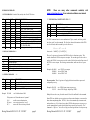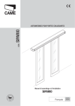
1
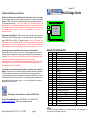
Version 4.22
RN-24 Usage Guide
COMMON PROBLEMS and QUESTIONS:
My Bluetooth client can see the RN-24 and its serial service, but I can’t connect:
This is most likely caused by a security setting on your client. If a pincode is required, the
default is “1234”. Some clients have these settings off by default, others have them on.
To check and disable security: From your PC desktop, click My Bluetooth Places, goto
the Bluetooth Device configuration (or Advanced Configuration) drop down menu, click on
the client applications tab, Select the Bluetooth serial port application name, and click on
the properties button, if “secure connection”, or “authentication”, or “encryption” is
checked, un check it.
Changing the clients COM port: Widcomm stack, (and others) allows you to connect to
RN-24 using a “Virtual COM” port mapper. The software installs with a default COM port,
usually COM3, COM4, or COM5. To change this setting: From your PC desktop, click
My Bluetooth Places, goto the Bluetooth Device configuration (or Advanced Configuration)
drop down menu, click on the client applications tab, Select the Bluetooth serial port
application name, and click on the properties button, then you can change the com port.
Connecting to more than one RN-24 from the same client at the same time:
Bluetooth allows 7 devices at a time in a piconet. Widcomm stack allows you to create
multiple instances of serial port profile and connect to multiple RN-24s at the same time.
To do this: From your PC desktop, click My Bluetooth Places, goto the Bluetooth Device
configuration (or Advanced Configuration) drop down menu, click on the
client applications tab, Select the Bluetooth serial port application name, and click on the
ADD COM port button, then you can add another Bluetooth serial port and assign it to
another virtual com port (such as COM9).
Connections can be made but during data transfer, no characters flow, or bytes are
dropped. Check to see if your flow control signals are properly connected, and enabled
in the serial software you are using. A common mistake is to connect during the boot
config timer window, in this case, all characters will be ignored until a $$$ is seen, and no
characters are forwarded to the remote device. If remote configuration is enabled, a safe
way to be sure to be in data mode is to issue “---“<cr> at the beginning of a connection
and before any user data is sent.
431 Monterey Avenue, Suite 5, Los Gatos, CA 95030 USA
Contact Roving Networks: phone 408-395-6539 fax 603-843-7550
[email protected] http://www.rovingnetworks.com
24 23 22 21 20 19 18 17 16 15 14 13
ANT
RN-24S (ANT)
RN-24E (SMA)
Class2
DIP module
SMA
LEDs
1 2
3 4 5 6 7 8 9 10 11 12
MODULE PIN CONFIGURATION
PIN
1
2
3
4
5
6
7
8
9
10
11
12
13
14
15
16
17
18
19
20
21
22
23
24
Name
RESET
GND
VCC
SPI_CS
SPI CK
SPI MO
SPI MI
CTS
TX
RTS
RX
VDD
TXO
RXI
RTSO
CTSI
PIO7
PIO6
PIO4
PIO3
PIO2
Function
Active HIGH
Option
Has 1k pulldown
3.3V power IN/OUT
NOTE A
Programming only
NO connect
Programming only
NO connect
Programming only
NO connect
Programming only
NO connect
Input TTL
Tie to RTS for 3 wire
Output TTL
Transmit data
Output TTL
Tie to CTS for 3 wire
Input TTL
Received data
4-20V DC power in
NOTE A
TX out RS232
Disable-remove R7
RX in RS232
Disable-remove R7
RTS out RS232
Disable-remove R7
CTS in RS232
Disable-remove R7
(default baudrate) HIGH= 9600, LO=115KGPIO
(auto master mode= HIGH)
GPIO
(factory defaults=HIGH, then toggle 3x)
GPIO
(auto discovery = HIGH)
GPIO
(connection status HIGH=connected)
GPIO
NOT USED
NOT USED
GND
NOTES:
Roving Networks RN-24 V 4.22 5/31/2007
page 8
A: The Power can be applied to EITHER pin 12, or pin 3, but NOT both. If pin 12 is powered, Pin 3
can be used as a 3.3V regulated supply output.
WARNING: take care not to exceed the voltage limits to the VCC, TTL SERIAL, and PIO pins.
0 negative voltage or voltage e xceeding 3.30VDC can permanently damage the device.
INSTANT CABLE REPLACEMENT EXAMPLE:
OPERATING MODES
0-Slave Mode - The default mode, other devices can discover and connect to the RN-24.
1 - Master Mode (SM,1<CR>) Enables outbound connections. To connect, use the “C” command.
2-Trigger Mode (SM,2<CR>) Automatically connects to stored address, when data is received on
local serial port of master.
3-Auto Master Mode (SM,3<CR>) Automatically connects to stored address on power up.
4-DTR Auto Master Mode (SM,4<CR>) Automatically connects/disconnects using PIO6 pin.
MASTER
SLAVE
1- PIO3 pulled High
2- PIO6 pulled High
1- PIO3 pulled High
1.
2.
3.
4.
Set PIO as shown above.
Power up both devices
Master finds and store slave address, and auto connects.
Remove Pullup on PIO3 (so that they don’t try to re-pair each time power is
cycled).
NOTE: In all master modes the device will not be discoverable or remote configurable.
LED
MODE
GREEN LED BLINK
Configuring
Boot up, Remote Configurable
Discoverable/Idle
Connected
Fast, 10 x per second
2 times per second
1 time per second
On Solid
YELLOW LED is driven by PIO8 and can be turned ON and OFF with software
commands. RED LED blinks when characters are received in command and slow data
modes.
DATA INTERFACE
The RN-24 can communicate via serial port using either TTL (0-3.3V DC) or RS-232 Levels.
Factory default enables the on-board RS232 chip. To Disable RS-232 and use TTL pins,
remove resistor R7 located on the bottom side of the module, near the tab of the power regulator.
PIO Pins
PIO
0
1
2
3
4
5
6
7
INPUT
INPUT
OUTPUT
INPUT
INPUT
OUTPUT
INPUT
INPUT
Powerup state
0
Not used
0
Not used
0
Goes high when connected
0
Auto discover mode when high
0
Factory reset when toggled 3 times
blinks
System status LED
0
Auto master mode/DTR mode when high
0
0=115K, 1=9600 default baudrate
These settings can be overridden by commands and the PIO pins can be used as general purpose
Input and output pins.
Roving Networks RN-24 V 4.22 5/31/2007
page 2
Roving Networks RN-24 V 4.22 5/31/2007
page 7
Making a Connection
The Power-up settings for the GPIO can also be viewed using the “E” (extended settings)
command.
WARNING:
GPIO-4 is used by the system to reset stored parameters to factory defaults. If GPIO4 is
pulled high on power-up, and then toggled 3 times, all user settings will return to default
values. Therefore this pin should not be used as an output, and should not be driven high
at power-up time (first 1 second of operation).
NOTE:
GPIO2 and 5 are driven by the embedded software as outputs, they can be disabled using
the direction command, (to save power, for example) and used as inputs. If set to
outputs the software will override any user values.
SETTING GPIO 8-9-10-11:
RN-24 shows up under Service discovery as “FireFly-zpdq” where the zpdq is the last 2
bytes of the Bluetooth address. To connect to RN-24, browse for services, you should
see: “SPP on Blueport-zpdq”. Default baudrate is 115200, no parity, 8 bits, 1 stop.
RN-24 uses Serial Port Profile and can be connected to as a Virtual COM port on PCs,
Palms, PocketPCs, or other clients.
NOTE: Only one client can connect to RN-24 at a time, and there is a limit of 7 total
devices in a Bluetooth Piconet network.
Changing Configuration
FROM LOCAL SERIAL PORT- Connect a null-modem cable (pins 2,3 swapped) from a
PC or a straight cable from an ASCII terminal to the RN-24. Communication settings of
your program should match the stored settings, for example: the default is 115,200Kbps,
8 bits, No Parity, 1 stop bit. Once you change these parameters, they will be stored
permanently.
S*,<hexword> = MASK[11..8] VALUE[11..8]
For the upper 4 GPIO, a single word controls the mask and values, and only the lower 4
bits of each byte are used. The first time this command is used, all 4 GPIO are driven as
outputs and remain so until a power cycle. There is no powerup command for these bits,
only the interactive one.
Run your favorite terminal emulator, hyperterminal or other program. (a free emulator for
the PC is available at www.rovingnetworks.com /support/teraterm.zip) ) Type $$$ on your
screen (3 dollar signs). You should see CMD returned to you. This will verify that your
cable and settings are correct. Valid commands will return an AOK. Errors in format will
return ERR, and unrecognized commands will return a ?. Type “h”<cr> to see a list of
commands, and “d”<cr> to see a summary of current settings.
Examples:
S*,0101
S*,0100
S*,0202
REMOTE VIA BLUETOOTH- Make a connection via bluetooth, then use your favorite
terminal emulator, and follow the directions above for local configuration. To return to data
mode, type a final “---“ ( 3 minus signs) <cr>, or reset the device and connect again.
GPIO-8 driven HIGH.
GPIO-8 driven LOW.
GPIO-9 driven HIGH.
GPIO8 pulls the YELLOW LED on when low, GPIO9 pulls the RED LED on when low
(and is driven in command mode and manual data mode),
NOTE: remote configuration can only occur if the bootup configuration timer (default 60
seconds) has not expired. This timer is set to 0 ( remote config disabled) for master
mode, and auto-connect slave mode, so that data can immediately flow between the 2
devices in cable replacement fashion.
GPIO10 and 11 are available on the 8 pin thru hole header on the
board edge. GPIO11 is the SQUARE pin, and GPIO 10 is the 3rd
pin down from GPIO11.
Roving Networks RN-24 V 4.22 5/31/2007
page 6
Roving Networks RN-24 V 4.22 5/31/2007
page 3
COMMAND SUMMARY
***SET COMMANDS ***stored in flash, and only take effect AFTER reboot
NOTE:
There are many other commands available, visit
www.rovingnetworks.com for an extensive software user manual.
VALUE
TYPE
DEFAULT DESCRIPTION
*** COMMANDS to MANIPULATE GPIO ***
SA
SE
SF
SL
SM
SN
SO
SP
SR
ST
SU
0,1
0,1
1
E,O,N
0,1,2,3
string
string
string
string
word
string
dec
dec
dec
char
dec
1-16 char
1-8
1-16 char
12 chars
seconds
2-4 char
0
0
CMD
SX
0,1
dec
CMD
Enable Authentication
Enable encryption
Reset to Factory Defaults
N
Parity, Even, Odd, or None
0
Mode (0-slav,1=mstr, 2=trig,3=auto ,4=DTR)
Blueport-x Bluetooth Name
NULL
Send connect/disconnect status string
1234
Security Pin Code
NOT SET Remote Address (123456789ABCDEF)
60
Config Timer(0=no config, 255=always on)
115K
Baudrate:1200,2400,4800,9600,19.2,38.4,
57.6,115k,230k,460k)
0
Bonding (locks to a single remote address)
*** DISPLAY COMMANDS ***
CMD
DESCRIPTION
D
E
G<X>
GB
&
V
Basic Settings
Extended Settings
A single setting matching the commands above
Bluetooth Address of this device
I/O Ports (shows the value of the switches)
Firmware Revision
*** OTHER COMMANDS
CMD
C
H
R
U
VAL1
VAL2
1
<rate> <E,O,N>
Example: SU,9600
Set direction bits for GPIO
Set values for GPIO
Store powerup direction bits for GPIO
Store powerup values for GPIO
Set values for PIO8,9,10,11
The GPIO command interface uses combination of 2bytes, a mask, and value, packed
into a hex word for each command. The first byte, the mask, determines which GPIO
are to be affected, and the second byte is the value to set.
15 --------- 8 7 -------- 0
<hexword> = MASK[7...0] VALUE[7..0]
Examples: S@,8080
S&,8080
S&,8000
***
Connect to Remote Address
Help, Show list of commands
Reboot device immediate
Temporary UART Change, immediate, not stored
sets Uart Baudrate to 9600
sets GPIO-7 to an output
drives GPIO-7 high
drives GPIO-7 low
Power-up values: These 2 registers will apply the direction and values upon each
subsequent power-up:
Examples: S%,0101
S^,0303
sets GPIO-0 to an output on power-up
drives GPIO-0 high, and pulls up GPIO-1.
Multiple bits can be set, any bits with a mask of 0 are left unaffected for the command.
SN,myname sets Bluetooth name to “myname”
SA,1
enables secure authentication
SP,secret
sets security pincode to “secret”
SF,1
restores all values to factory defaults
Roving Networks RN-24 V 4.22 5/31/2007
<hexword>
<hexword>
<hexword>
<hexword>
<hexword>
DESCRIPTION
There are 2 registers used to control the GPIO, the first is a direction register. This
controls whether the GPIO is an input or an output. The second register is the value to
apply to the GPIO if set to an output, or is the value of the built-in weak pull-up resistor if
the GPIO is set to an input. These settings are immediate, and do not survive a power
cycle.
DESCRIPTION
<addr>
@
&
%
^
*
VALUE
Some GPIO are checked at power-up time to perform certain functions, so care must be
taken when manipulating them. GPIO3, 6, are used to automatically set master mode,
and auto discovery. If it is desired to use these GPIO for other purposes at power-up, a
special command must be used to disable their being sensed at power-up time. This
command is “SQ,4<cr>” this will set a flag in a stored register that is read at power-up.
page 4
Roving Networks RN-24 V 4.22 5/31/2007
page 5