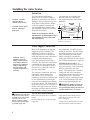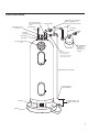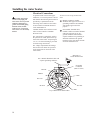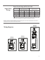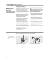
1
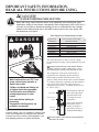
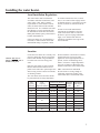
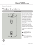
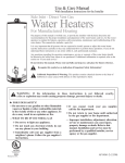
Use & Care Manual With Installation Instructions for the Installer Electric Water Heaters Single and Double Element Models, 15–105 Gallon The purpose of this manual is twofold: one, to provide the installer with the basic directions and recommendations for the proper installation and adjustment of the water heater; and two, for the owner–operator, to explain the features, operation, safety precautions, maintenance and troubleshooting of the water heater. This manual also includes a parts list. ■■■✦■■■ ■■■✦■■■ ■■■✦■■■ ■■■✦■■■ It is imperative that all persons who are expected to install, operate or adjust this water heater read the instructions carefully so they may understand how to perform these operations. If you do not understand these instructions or any terms within it, seek professional advice. Any questions regarding the operation, maintenance, service or warranty of this water heater should be directed to the seller from whom it was purchased. If additional information is required, refer to the warranty. Do not destroy this manual. Please read carefully and keep in a safe place for future reference. ! ! Recognize this symbol as an indication of Important Safety Information! alifornia Proposition 65 Warning: C This product contains chemicals known to the State of California to cause cancer, birth defects or other reproductive harm. Printed in USA 1298-001 (01/10) Safety Information Safety Precautions. . . . . . . 3, 4 FOR YOUR RECORDS Write the model, serial numbers, and installation details on the back cover of the manual. This information is located on the rating plate (silver label) on the unit. Staple sales slip or cancelled check here. Installation Instructions Location. . . . . . . . . . . . . . . . . . 5 Proof of the original purchase date is needed to obtain service under the warranty. Water Connections . . . . . . . . . 8 Electrical Connections. . . . . 10 Wiring Diagram. . . . . . . . . . 11 READ THIS MANUAL Operating Instructions Inside you will find many helpful hints on how to use and maintain your water heater properly. Just a little preventive care on your part can save you a great deal of time and money over the life of your water heater. Safety Controls . . . . . . . . . . 14 Water Temperature . . . . . . . . 14 You’ll find many answers to common problems in the Before You Call For Service section. If you review our chart of Troubleshooting Tips first, you may not need to call for service at all. READ THE SAFETY INFORMATION Care and Cleaning Draining. . . . . . . . . . . . . . . . 16 Your safety and the safety of others are very important. There are many important safety messages in this manual and on your appliance. Always read and obey all safety messages. Maintenance. . . . . . . . . . . . . 16 ! Extended Shut-Down. . . . . 16 Troubleshooting Tips Before You Call For Service. . . . . . . . . . . . . . 17 This is the safety alert symbol. Recognize this symbol as an indication of Important Safety Information! This symbol alerts you to potential hazards that can kill or hurt you and others. All safety messages will follow the safety alert symbol and either the word “DANGER”, “WARNING”, “CAUTION” or “NOTICE”. These words mean: An imminently hazardous situation ! DANGER that will result in death or serious injury. WARNING A potentially hazardous situation that could result in death or serious injury and/or damage to property. Replacement Parts. . . . . . 19, 20 A potentially hazardous situation that may result in minor or moderate injury. Element Replacement. . . . . 21 Notice: ! Customer Service Parts List. . . . . . . . . . . . . . . . 18 Warranty. . . . . . . . . . . . . . . . . 22 2 ! CAUTION Attention is called to observe a specified procedure or maintain a specific condition. IMPORTANT SAFETY INFORMATION. READ ALL INSTRUCTIONS BEFORE USING. DANGER! water temperature setting Safety and energy conservation are factors to be considered when selecting the water temperature setting of water heater’s thermostat. Water temperatures above 125°F (51°C) can cause severe burns or death from scalding. Be sure to read and follow the warnings outlined on the label pictured below. This label is also located on the water heater near the thermostat access panel. Time/Temperature Relationship in Scalds ! DANGER Temperature Time To Produce a Serious Burn 120°F (49°C) 125°F (51°C) 130°F (54°C) 135°F (57°C) 140°F (60°C) 145°F (63°C) 150°F (66°C) 155°F (68°C) More than 5 minutes 1½ to 2 minutes About 30 seconds About 10 seconds Less than 5 seconds Less than 3 seconds About 1½ seconds About 1 second Table courtesy of Shriners Burn Institute T ESE NOTICE: Mixing valves are available for reducing point of use water temperature by mixing hot and cold water in branch water lines. Contact a licensed plumber or the local plumbing authority for further information. Reset button R Children, disabled and elderly are at highest risk of being scalded. See instruction manual before setting temperature at water heater. Feel water before bathing or showering. Temperature limiting valves are available, see manual. The temperature of the water in the heater is regulated by the adjustable surface mounted thermostat(s) located behind the jacket access panel(s). Dual element heaters have two thermostats. To comply with safety regulations the thermostat(s) were set at 120°F before the water heater was shipped from the factory. Canadian models are set to 140°F (60°C). ESE Water temperature over 125°F can cause severe burns instantly or death from scalds. ! DANGER: Households with small children, disabled, or elderly persons may require a 120°F (49°C) or lower thermostat setting to prevent contact with “HOT” water. R BURN The chart shown above may be used as a guide in determining the proper water temperature for your home. T HOT Thermostat dial pointer 150°F (66°C) Thermostat protective cover 90°F (32°C) 125°F (52°C) TURN OFF POWER BEFORE SERVICING The illustration at the left shows the temperature adjustment dial used for setting the water temperature. Refer to the Operating Instructions in this manual for detailed instructions in how to adjust the thermostat(s). ! DANGER: Hotter water increases the potential for Hot Water SCALDS. 3 IMPORTANT SAFETY INFORMATION. READ ALL INSTRUCTIONS BEFORE USING. WARNING! For your safety, the information in this manual must be followed to minimize the risk of fire or explosion, electric shock, or to prevent property damage, personal injury, or loss of life. Be sure to read and understand the entire Use and Care Manual before attempting to install or operate this water heater. It may save you time and cost. Pay particular attention to the Safety Instructions. Failure to follow these warnings could result in serious bodily injury or death. Should you have problems understanding the instructions in this manual, or have any questions, STOP, and get help from a qualified service technician, or the local electric utility. FOR INSTALLATIONS IN THE STATE OF CALIFORNIA California Law requires that residential water heaters must be braced, anchored or strapped to resist falling or horizontal displacement due to earthquake motions. For residential water heaters up to 52 gallon capacity, a brochure with generic earthquake bracing instructions can be obtained from: Office of the State Architect, 1102 Q Street, Suite 5100, Sacramento, CA 95811 or you may call 916-445-8100 or ask a water heater dealer. However, applicable local codes shall govern installation. For residential water heaters of a capacity greater than 52 gallons, consult the local building jurisdiction for acceptable bracing procedures. SAFETY PRECAUTIONS Have the installer show you the location of the circuit breaker and how to shut it off if necessary. Turn off the circuit breaker if the water heater has been subjected to overheating, fire, flood, physical damage or if the ECO (Emergency Cut Off) on the thermostat fails to shut off. of your water heater unless it is specifically ● Read this manual entirely before installing recommended in this manual. All other or operating the water heater. servicing should be referred to a qualified ● Use this appliance only for its intended technician. purpose as described in this Use and Care ● All replacement parts used on this Manual. product must be manufacturer authorized ● Be sure your appliance is properly installed components. in accordance with local codes and the provided installation instructions. ● Do not attempt to repair or replace any part Read and follow this Safety Information carefully. SAVE THESE INSTRUCTIONS 4 Installing the water heater. Local Installation Regulations This water heater must be installed in accordance with these instructions, local codes, utility codes, utility company requirements or, in the absence of local codes, the latest edition of the National Electrical Code. It is available from some local libraries or can be purchased from the National Fire Protection Association, Batterymarch Park, Quincy, MA 02269 as booklet ANSI/NFPA 70. If the water heater is to be installed in a restaurant, or other location where NSF International listing is required, it must be weather sealed to the floor, a raised base, or on a shelf so that seepage cannot accumulate under it; or elevated to provide at least (6) inches of clearance from the floor. In order to meet NSF International requirements for Standard 5, the base of the water heater must be sealed to the floor to prevent seepage underneath. Apply a 3/8" bead of RTV Silicone completely around the floor edge of the base of the tank. The location chosen for the water heater must take into consideration the following: Location NOTICE: DO NOT use fittings on top of the unit as handles or lift points. Locate the water heater in a clean dry area as near as practical to the area of greatest heated water demand. Long un-insulated hot water lines can waste energy and water. Place the water heater in such a manner that the thermostat and element access panels can be removed to permit inspection and servicing such as removal of elements or checking controls. The water heater and water lines should be protected from freezing temperatures. Unit Capacity (Gallons) 15 20 30 40 50 50S 75 85 105 1 Unit Capacity (Imperial Gallons) 13 17 25 33 42 63 71 88 Do not install the water heater in outdoor, unprotected areas or near any other appliances where high temperatures are present, such as wood burning stoves, boilers, or furnaces. High temperatures can warp or otherwise damage the nonmetallic construction of this water heater. Make certain the floor underneath the water heater is strong enough to sufficiently support the weight of the water heater once it is filled with water. Dimensions (Inches) Height 1 Diameter 35 5/8 34 1/2 53 65 1/2 66 3/4 47 1/4 62 5/8 70 1/4 70 3/4 21 5/8 23 1/2 21 5/8 21 5/8 23 1/2 28 1/4 28 1/4 28 1/4 30 1/4 Shipping Approximate Weight Full Weight (lbs) (lbs) 58 183 61 228 75 325 90 424 100 517 95 512 122 748 134 843 152 1,028 Height includes factory installed Temperature and Pressure Relief Valve. 5 Installing the water heater. Thermal Expansion Determine if a check valve exists in the inlet water line. Check with your local water utility. It may have been installed in the cold water line as a separate back flow preventer, or it may be part of a pressure reducing valve, water meter or water softener. A check valve located in the cold water inlet line can cause what is referred to as a “closed water system”. A cold water inlet line with no check valve or back flow prevention device is referred to as an “open” water system. As water is heated, it expands in volume and creates an increase in the pressure within the water system. This action is referred to as “thermal expansion”. In an “open” water system, expanding water which exceeds the capacity of the water heater flows back into the city main where the pressure is easily dissipated. A “closed water system”, however, prevents the expanding water from flowing back into the main supply line, and the result of “thermal expansion” can create a rapid and dangerous pressure increase in the water heater and system piping. This rapid pressure increase can quickly reach the safety setting of the relief valve, causing it to operate during each heating cycle. Thermal expansion, and the resulting rapid and repeated expansion and contraction of components in the water heater and piping system can cause premature failure of the relief valve, and possibly the heater itself. Replacing the relief valve will not correct the problem! The suggested method of controlling thermal expansion is to install an expansion tank in the cold water line between the water heater and the check valve (refer to the illustration on page 9). The expansion tank is designed with an air cushion built in that compresses as the system pressure increases, thereby relieving the over pressure condition and eliminating the repeated operation of the relief valve. Other methods of controlling thermal expansion are also available. Contact your installing contractor, water supplier or plumbing inspector for additional information regarding this subject. Inspect Water Heater Inspect the water heater for possible damage. Check the markings on the rating plate of the water heater to be certain the power supply corresponds to the water heater requirements. 6 Temperature and Pressure Relief Valve A new combination temperature and pressure relief valve, complying with the Standard for Relief Valves and Automatic Gas Shut-Off Devices for Hot Water Supply Systems, ANSI Z21.22, is supplied and must be installed in the opening provided and marked for the purpose on the water heater. No valve of any type should be installed between the relief valve and the tank. Local codes shall govern the installation of relief valves. ! WARNING: The pressure rating of the relief valve must not exceed 150 PSI, (1034 KPA), the maximum working pressure of the water heater as marked on the rating plate. The BTUH rating of the relief valve must not be less than the input rating of the water heater as indicated on the rating label located on the front of the heater (1 watt=3.412 BTUH). Connect the outlet of the relief valve to a suitable open drain so that the discharge water cannot contact live electrical parts or persons and to eliminate potential water damage. Piping used should be of a type approved for hot water distribution. The discharge line must be no smaller than the outlet of the valve and must pitch downward from the valve to allow complete drainage (by gravity) of the relief valve and discharge line. The end of the discharge line should not be threaded or concealed and should be protected from freezing. No valve of any type, restriction or reducer coupling should be installed in the discharge line. Vacuum Relief Valve NOTICE: Do NOT remove or tamper with the vacuum relief valve for any reason. Doing so will void the manufacturer’s warranty. The vacuum relief valve, which must be used when installing the water heater, is factory installed. The cold water inlet has a vacuum relief valve connected to it. Certain conditions in the field may produce a vacuum or negative pressure condition inside the water heater’s tank. This negative pressure can cause the tank to fail. The vacuum relief valve provides a means to eliminate the negative pressure or vacuum by admitting air into the tank to equalize the pressure. It is not recommended to pull a vacuum on the unit. If a vacuum is pulled on the unit, refer to the "To Fill the Water Heater" section to ensure the unit is full of water before operating. 7 Installing the water heater. Drain Pan NOTICE: Auxiliary catch pan MUST conform to local codes. NOTICE: Water heater must be centered in drain pan. The water heater should not be located in an area where leakage of the tank or connections will result in damage to the area adjacent to it or to lower floors of the structure. Where such areas cannot be avoided, it is recommended that a suitable catch pan, adequately drained, be installed under the water heater. Under no circumstance will the manufacturer be held liable for any water damage in connection with this water heater. Catch pan kits are available from the store where the water heater was purchased, or any water heater distributor. B = Max 2″ B A = Diameter of water heater plus 2″ min. A To open drain, this line should be at least 3/4″ ID and pitched for proper drainage. Water Supply Connections NOTICE: Do not attempt to turn any fitting connected to the water heater union hex nuts that are tightened. Doing so will damage the water heater and void the manufacturer’s warranty. ! WARNING: The tank must be full of water before heater is turned on. The water heater warranty does not cover damage or failure resulting from operation with an empty or partially empty tank. 8 Refer to the illustration on right for suggested typical installation. The installation of unions or flexible copper connectors is recommended on the hot and cold water connections so that the water heater may be easily disconnected for servicing if necessary. The HOT and COLD water connections are clearly marked and are 3/4″ NPT on all models. Install a shut-off valve in the cold water line near the water heater. The cold water connection, hot water connection, and the temperature and pressure relief valve may be temporarily disconnected from the unit to ease installation by loosening the union hex nuts connecting the fittings to the water heater. The connection of these parts to the unit use seal rings to form a water tight connection. Re-use the rubber seal rings that are provided with the heater when re-installing To Fill the Water Heater Make certain the drain valve is completely closed. Open the shut-off valve in the cold water supply line. the components. Do NOT use pipe sealant on this joint. Do NOT torque the union hex nuts to over 35 ft-lbs when reinstalling the components. Failure to properly reconnect the fittings provided with the water heater will void the manufacturer’s warranty. SOLDER WITH CARE!!! If sweat connections are used, do NOT apply heat directly to any component directly connected to the water heater. This includes the cold water connection, hot water connection, temperature and pressure relief valve and the drain valve. Assemblies should be built to a minimum length of 12” before attaching to the water heater to avoid damaging the unit. WARNING: Failure to follow the instructions provided in this manual may permanently damage the unit and void the manufacturer’s warranty. ! Open each hot water faucet slowly to allow the air to vent from the water heater and piping. A steady flow of water from the hot water faucet(s) indicates a full water heater. Typical Installation Temperature & Pressure Relief Valve Pre-solder 12" minimum stub pipes before installing to unit. Support the relief valve drain pipe using metal strapping or wire fastened to the structure overhead Cold Inlet Shut Off Hot Water Outlet Heat Trap 6" Minimum Seal Ring (Inside nut) Hex Union Nut (Relief Valve) Top of Water Heater Junction Box Thermal Expansion Tank (if required) See thermal expansion section on page 6. ■■■✦■■■ Union (The addition of a union at this point will help in the replacement of the T & P Relief Valve should the need arise.) Drain Pipe -(3/4" minimum) No threads permitted on end of Drain Pipe. Drain Valve 6” Maximum distance from drain pipe to suitable open drain. Drain Pan 9 Installing the water heater. Electrical Connections ! CAUTION: The presence of water in the piping and water heater does not provide sufficient conduction for a ground. Non-metallic piping, dielectric unions, flexible connectors etc. can cause the water heater to be electrically isolated. A separate branch circuit with copper conductors, over current protective device and suitable disconnecting means must be provided by a qualified electrician. All wiring must conform to local codes or latest edition of National Electrical Code ANSI/NFPA 70. Canadian models must conform to local codes or latest edition of Canadian Electrical Code. The water heater is completely wired to the junction box inside jacket at the top front of the water heater. An opening for 1/2″ or 3/4″ electrical fitting is provided for field wiring connections. The branch circuit wiring should include either: etallic conduit or metallic M sheathed cable approved for use as a grounding conductor and installed with fittings approved for the purpose. on-metallic sheathed cable, N metallic conduit or metallic sheathed cable not approved for use as a ground conductor shall include a separate conductor for grounding. It should be attached to the ground terminals of the water heater and the electrical distribution box. The voltage requirements and wattage load for the water heater are specified on the rating plate on the front of the water heater. Main Fuse or Circuit Breaker Panel Non - Metallic Sheathed Cable with separate grounding conductor. Grounding Conductor (Bare or Green) BLACK GREEN RED Wire Nut Wire Nut BLACK Top of Water Heater Junction Box 10 RED Branch Circuit Sizing and Wire Size Guide Single Phase Wiring Total Water Heater Wattage 2,000 3,000 3,800 4,500 Recommended Over Current Protection Copper (fuse or circuit breaker amperage rating) 120V 240V 20 ------20 ---20 ---25 Wire Size AWG Based on N.E.C. Table 310-16 (75°C) 120V 12 ---------- 240V ---12 12 10 ! DANGER: Elements should only be replaced with an element of the same power rating that was factory installed, and corresponds to the rating label on the unit. NOTICE: This guide recommends minimum branch circuit sizing and wire size based on National Electric Code. Refer to wiring diagrams in this manual for field wiring connections. 240 Volt Wiring Diagrams DOUBLE ELEMENT L2 1 240 Volt SINGLE ELEMENT RED 2 4 1 4 UPPER THERMOSTAT & HIGH TEMP. LIMIT (ECO) 2 YELLOW 120 Volt 3 BLUE * G BLACK L1 JUNCTION BOX BRANCH CIRCUIT TO ELECTRICAL DISTRIBUTION PANEL SINGLE ELEMENT BRANCH CIRCUIT TO ELECTRICAL DISTRIBUTION PANEL 3 2 4 THERMOSTAT & HIGH TEMP. LIMIT (ECO) YELLOW BLUE YELLOW RED BLACK N THERMOSTAT & HIGH TEMP. LIMIT (ECO) 2 1 HEATING ELEMENT * 1 1 2 G LOWER THERMOSTAT 1 2 YELLOW RED 1 H WHITE L2 BLACK * JUNCTION BOX G BLACK L1 UPPER HEATING ELEMENT JUNCTION BOX BRANCH CIRCUIT TO ELECTRICAL DISTRIBUTION PANEL 2 HEATING ELEMENT LOWER HEATING ELEMENT 11 Installing the water heater. Insulation Blankets ! WARNING: If local codes require external application of insulation blanket kits the manufacturer’s instructions included with the kit must be carefully followed. Insulation blankets, available to the general public, for external use on electric water heaters are not necessary. The purpose of an insulation blanket is to reduce the standby heat loss encountered with storage tank heaters. This water heater meets or exceeds the National Appliance Energy Conservation Act standards with respect to insulation and standby loss requirements making an insulation blanket unnecessary. The manufacturer’s warranty does not cover any damage or defect caused by installation, attachment or use of any type of energy saving or other unapproved devices (other than those authorized by the manufacturer) into, onto or in conjunction with the water heater. The use of unauthorized energy saving devices may shorten the life of the water heater and may endanger life and property. ! CAUTION: If local codes require the application of an external insulation blanket to this water heater, pay careful attention to the following so as not to restrict the proper function and operation of the water heater: Do not cover the operating or warning labels attached to the water heater or attempt to relocate them on the exterior of insulation blanket. Do not apply insulation to the top of the water heater. This could interfere with the safe operation of the electrical junction box. Do not cover the jacket access panel(s) to the thermostat(s) and heating element(s), vacuum valve, or pressure and temperature relief valve. Inspect the insulation blanket frequently. The manufacturer disclaims any responsibility for such loss or injury resulting from the use of such unauthorized devices. Hot and Cold Pipe Insulation Installation Notice: Do not cover or block opening on vacuum valve 12 Vacuum Valve Vacuum Valve Typical vertical piping arrangement Typical horizontal piping arrangement For increased energy efficiency, some water heaters have been supplied with two 24” sections of pipe insulation. Please install the insulation, according to the illustrations above, that best meets your requirements. Installation Checklist A. Water Heater Location ❑ Close to area of heated water demand. ❑ Indoors and protected from freezing temperatures. ❑ Area free of flammable vapors. ❑ Provisions made to protect area from water ❑ Sufficient room to service heater. damage. B. Water Supply ❑ Water heater completely filled with water. ❑ Air purged from water heater and piping. ❑ Water connections tight and free of leaks. C. Relief Valve ❑ Temperature and Pressure Relief Valve properly installed and discharge line run to open drain. ❑ Discharge line protected from freezing. D. Wiring ❑Power Supply voltage agrees with water heater rating plate. ❑Branch circuit wire and fusing or circuit breaker of proper size. ❑Electrical connections tight and unit properly grounded. 13 Operating the water heater. Safety Precautions o turn off power to water heater if D it has been subjected to over heating, fire, flood, physical damage. o Not turn on water heater unless it D is filled with water. o Not turn on water heater if cold D water supply shut-off valve is closed. Care and Cleaning section, it is recommended that a qualified person or serviceman perform the work. The unit must be completely filled with water before turning on the power. there is any difficulty in If understanding or following the Operating Instructions or the Safety Controls NOTICE: It is important that the fiberglass insulation is replaced to maintain water heater's performance. WARNING: If the water heater has been subjected to flood, fire, or physical damage, turn off power and water to the water heater. Do not operate the water heater again until it has been thoroughly checked by qualified service personnel. The water heater is equipped with a combination thermostat and temperature limiting control (ECO) that is located above the heating element in the upper control box. If for any reason the water temperature becomes excessively high, the temperature limiting control (ECO) breaks the power circuit to the heating element. Once the control opens, it must be reset manually. CAUTION: The cause of the high temperature condition must be investigated by qualified service technician and corrective action must be taken before placing the water heater in service again. To reset the temperature limiting control: urn off the power to the water T heater. emove the jacket access panel(s) R and insulation from the top control box. he thermostat protective cover T should not be removed. Press the red RESET button. eplace the insulation and jacket R access panel(s) before turning on the power to the water heater. Water Temperature Setting ! DANGER: There is a hot water scald potential if the thermostat is set too high. Households with small children, disabled, or elderly persons may require a 120°F (49°C) or lower thermostat setting to prevent contact with HOT water. ! DANGER: The water heater will experience the highest water temperatures the first time the unit is operated as it is conditioned and the temperature stabilizes. 14 The temperature of the water in the water heater can be regulated by setting the temperature dial of the adjustable surface mounted thermostat(s) located behind the jacket access panel(s). Dual element heaters have two thermostats. Safety and energy conservation are factors to be considered when selecting the water temperature setting of the water heater’s thermostat(s). The lower the temperature setting, the greater the savings in energy and operating costs. To comply with safety regulations the thermostat(s) are factory set at 120°F or less where local codes require. Canadian models are set to 140° F (60° C). These are the recommended starting points. Water temperatures above 125°F (51°C) can cause severe burns or death from scalding. Be sure to read and follow the warnings outlined in this manual and on the label on the water heater. This label is located on the water heater near the thermostat access panel. Mixing valves for reducing point of use water temperature by mixing hot and cold water in branch water lines are available. Contact a licensed plumber or the local plumbing authority for further information. The chart on the next page may be used as a guide in determining the proper water temperature for your home. If adjustment is necessary… To increase the water temperature, it is recommended to adjust the bottom thermostat only. Turn off the power to the water heater. ! DANGER: Make certain power to the water heater is "OFF" before removing any jacket access panel for any reason. Failure to do so could result in property damage, bodily injury, or death. Thermostat dial pointer HIGH (66°C) LOW MED T R E R emove the snap-in access panel R cover. Insert finger into latch hole on the bottom of the cover and push up to release the latch. Pull forward and remove the cover and insulation. Reset button ESE T T R ESE To decrease water temperature, all thermostats on the unit need to be adjusted to the lower setting. 15 0°F (32°C) (52°C) 12 5°F 90 °F TURN OFF POWER BEFORE SERVICING TURN OFF POWER BEFORE SERVICING Thermostat protective cover Bottom Thermostat (Dual Thermostat Models) Top Thermostat or Single Thermostat Models emove the (4) screws that secure R the jacket access panel to the unit. Remove the jacket access panel and insulation exposing the thermostats. Use care when removing insulation pads. he thermostat protective cover should T not be removed. sing a small screwdriver, set the U thermostat dial pointer to the desired temperature by turning the screw. Do not pry or move the white plastic pointer. HIGH ≈ 150°F (66° C) Water Temperature eplace the rectangular insulation and R thermostat access panel. Secure the panel to the unit using the (4) screws provided. Tighten the screws until only snug. It is important that the fiberglass insulation is replaced to maintain water heater's performance and safety. Turn on the power to the water heater. LOW ≈ 90°F (32° C) Water Temperature MED ≈ 120°F (49° C) Water Temperature eplace the access panel cover and R insulation and snap in position. Time/Temperature Relationship in Scalds Temperature Time To Produce a Serious Burn 120°F (49°C) 125°F (51°C) 130°F (54°C) 135°F (57°C) 140°F (60°C) 145°F (63°C) 150°F (66°C) 155°F (68°C) More than 5 minutes 11/2 to 2 minutes About 30 seconds About 10 seconds Less than 5 seconds Less than 3 seconds About 11/2 seconds About 1 second Table courtesy of Shriners Burn Institute 15 Care and cleaning of the water heater. Draining the Water Heater Shut off power to the water heater. Open the drain valve. pen a hot water faucet nearest the O water heater. Run water until cold. Drain water heater completely. urn off the cold water supply to T the water heater. Close the relief valve. Leave the hot water faucet open. ttach a garden hose to the drain A valve on the bottom of the water heater and direct the hose to a drain. ift open the handle on the relief L valve, and leave open. (top center fitting on water heater) (some water may be released) Close the drain valve. NOTICE: Additional instructions for draining the unit are located on the water heater. Please reference the "To Fill the Water Heater" section (see page 8) for instructions on how to refill the unit. Routine Preventative Maintenance DANGER: Before manually operating the relief valve, make certain no one will be exposed to the danger of coming in contact with the hot water released by the valve. The water may be hot enough to create a scald hazard. The water should be released into a suitable drain to prevent injury or property damage. NOTICE: If the temperature and pressure relief valve on the hot water heater discharges periodically, this may be due to thermal expansion in a closed water system. Contact the water supplier or your plumbing contractor on how to correct this. Do not plug the relief valve outlet. Properly maintained, your water heater will provide years of dependable troublefree service. It is suggested that a routine preventive maintenance program be established and followed by the user. It is further recommended that a periodic inspection of the operating controls, heating elements and wiring should be made by service personnel qualified in electric appliance repair. Most electrical appliances, even when new, make some sound when in operation. If the hissing or singing sound level increases excessively, the electric heating element may require cleaning. Contact a qualified installer or plumbing contract to inspect. At least once a year, lift and release the lever handle on the temperature pressure relief valve, located near the top of the water heater, to make certain the valve operates freely. Allow several gallons to flush through the discharge line to an open drain. A water heater’s tank can act as a settling basin for solids suspended in the water. It is therefore not uncommon for hard water deposits to accumulate in the bottom of the tank. It is suggested that a few quarts/ liters of water be drained from the water heater’s tank every month to clean the tank of these deposits. Rapid closing of faucets or solenoid valves in automatic water using appliances can cause a banging noise heard in a water pipe. Strategically located risers in the water pipe system or water hammer arresting devices can be used to minimize the problem. Vacation and Extended Shut-Down If the water heater is to remain idle for an extended period of time, the power and water to the appliance should be turned off to conserve energy. If the water heater is installed in a location where it could freeze when not operational, all water must be drained from the unit and piping If the tank is full of water and freezes, the tank will break. See the "Draining the Water Heater" 16 section for details on draining the unit. Freeze damage is not covered under the manufacturer's warranty. After a long shut-down period, the water heater’s operation and controls should be checked by qualified service personnel. Make certain the water heater is completely filled again before placing it in operation. Before You Call For Service… Troubleshooting Tips Save time and money! Review the chart on this page first and you may not need to call for service. Problem Possible Causes Rumbling noise Water conditions in your home caused R emove and clean the heating elements. Contact a qualified service technician. a build up of scale or mineral deposits on the heating elements. Relief valve producing popping noise or draining Pressure build up caused by thermal expansion in a closed system. Not enough or no hot water Water usage may have exceeded the capacity of the water heater. A fuse is blown or a circuit breaker tripped. Electric supply may be off. The thermostat may be set too low. Leaking or open hot water faucets. Electric service to your home may be interrupted. Improper wiring. Water is too hot What to Do T his is an unacceptable condition and must be corrected. Contact the water supplier or plumbing contractor on how to correct this. Do not plug the relief valve outlet. W ait for the water heater to recover after an abnormal demand. R eplace fuse or reset circuit breaker. M ake sure electric supply to water heater and disconnect switch, if used, are in the ON position. S ee the Temperature regulation of the water heater section of this manual. M ake sure all faucets are closed. C ontact the local electric utility. S ee the Installing the water heater section Manual reset limit (ECO). Cold water inlet temperature may be colder during the winter months. Top element defective (no hot water) Bottom element defective (small quantity of hot water) The thermostat is set too high. Covers and / or insulation missing. of this manual. S ee the Temperature regulation of the water heater section of this manual. T his is normal. The colder inlet water takes longer to heat. R eplace element. R eplace element. S ee the Temperature regulation of the water heater section of this manual. R einstall covers and insulation. ! CAUTION: For your safety DO NOT attempt repair of electrical wiring, thermostats, heating elements or other safety devices. Refer repairs to qualified service personnel. 17 Replacement Parts. Key No. 1 2 3 4 5 6 7 8 9 10 11 12 13 14 15 16 17 18 19 20 21 22 23 24 25 26 27 28 ▲ ▲ ▲ ▲ 18 Description Dip Tube Grommet, Large Grommet, Small Seal Ring, Large Seal Ring, Small Vacuum Valve Assembly Temperature and Pressure Relief Valve Nipple, 3/4" NPT x 3" Reducer Bushing, 3/4" NPT x 1" NPT Knock-Out Bracket Screw, #8 x 3/4" Junction Box Cover Screw #8-16 x 5/8" Upper Thermostat Upper Protector Screw, #10-16 x 5/8" Thermostat Cavity Insulation Upper Access Panel Screw, #10-16 x 5/8" Access Panel Cover Insulation Access Panel Cover Element Gasket Upper Heating Element (Includes Key No. 20) Lower Thermostat Lower Protector Lower Access Panel Lower Heating Element (Includes Key No. 20) Drain Valve 5/16-18 Cap Screw Lock Washer Element Wrench Pipe Wrap Energy Kit Use and Care Manual Not Illustrated Replacement Parts. 30-105 gallon models. 6 5 7 8 9 10 11 13 15 12 14 ................ 20 16 19 21 18 17 23 22 15 14 ................ 20 24 19 18 17 3 25 7 26 19 Replacement Parts. 15-20 gallon models. ................ 20 Element Replacement Instructions on the unit are clean. Brush debris off of threads with a toothbrush if needed. 1. Turn off power to the unit. ! DANGER: Make certain power to the water heater is “OFF” before removing any jacket access panel for any reason. Failure to do so could result in property damage, bodily injury, or death. 2. O pen a hot water faucet and allow water to flow until the water is cold. 3. E mpty the water out of the unit by following the instructions given in the “Draining the Water Heater” section (see page 16) of this manual. 4. R emove the snap-in access panel cover. Insert finger into latch hole on the bottom of the cover and push up to release the latch. Pull forward and remove the cover and insulation. 30-105 GALLON 5. R emove the (4) screws that secure the jacket access panel to the unit. Remove the jacket access panel and insulation exposing the thermostat and element. Use care when removing the insulation pads. 6. F lip up the bottom of the plastic protector up to expose the head of the heating element. 7. L oosen the terminal screws on the element to disconnect the two wires and slightly bend them away from the element. 8. U sing a wrench or socket to fit the 1 7/8 inch hex nut, remove the old element. For 15 and 20 gallon units use a 1/2 inch socket and remove the (4) bolts and lock washers on the element. NOTICE: An element wrench is available for purchase through your water heater distributor. NOTICE: Make sure the threads OTICE: The elements are unique N to the upper and lower port. Make certain the replacement element is correct for the port into which you are installing it. 9. O n the new element make certain the element gasket is in place and not twisted. 10. Thread the new element into the tank and tighten with a wrench or socket to 13 – 15 ft-lbs. For 15 and 20 gallon units install the element with the arrow on the head pointing “UP” using the same bolts and lock washers that were removed in step 8. OTICE: Do not over tighten the N element. Do not apply torque over 18 ft-lbs. 11. Reconnect the two wires to the element and tighten the terminal screws. 12. Reference the “To Fill the Water Heater” section of this manual for instructions on refilling the unit. 13. After the unit is completely filled with water and under pressure, verify the element is properly installed with no water leakage. 14. Lower the protector to cover the head of the heating element. 15. Replace the rectangular insulation and thermostat access panel. Secure the panel to the unit using the (4) screws provided. Tighten the screws until only snug. 16. Replace the access panel cover and insulation and snap in position. 17. Turn on power to the water heater. 15/20 GALLON 21 LIMITED WARRANTY Marathon Electric Water Heaters EXCLUSIVE WARRANTY – LIMITATION OF LIABILITY This Limited Warranty is the only Warranty for this unit given by Water Heater Innovations, a subsidiary of Rheem Manufacturing Company. No one is authorized to make any other warranties on our behalf. ANY IMPLIED WARRANTIES, INCLUDING MERCHANTABILITY, OR FITNESS FOR A PARTICULAR PURPOSE, SHALL NOT EXTEND BEYOND THE APPLICABLE WARRANTY PERIODS SPECIFIED PREVIOUSLY. RHEEM’S SOLE LIABILITY, WITH RESPECT TO ANY DEFECT, SHALL BE AS SET FORTH IN THIS LIMITED WARRANTY, AND ANY CLAIMS FOR INCIDENTAL OR CONSEQUENTIAL DAMAGES (INCLUDING DAMAGE FROM WATER LEAKAGE) ARE EXCLUDED. Some states do not allow limitations on how long an implied warranty lasts, or for the exclusion of incidental or consequential damages, so the above limitations or exclusions may not apply to you. This Limited Warranty gives you specific legal rights, and you may also have other rights, which vary from state to state. We suggest you immediately complete the information below and retain it in the event warranty service is needed. Reasonable proof of the date of installation of your water heater may be required to establish its “in-warranty” status. Otherwise, the Effective Date of this Limited Warranty will be the date of manufacture of the water heater plus ninety (90) days. GENERAL Water Heater Innovations, Inc. warrants its products to be free from factory defects in materials and workmanship, under normal use and service, for the Applicable Warranty Period. At its option, Water Heater Innovations will repair or replace the defective water heater, or defective component part(s), in accordance with the terms of this Limited Warranty, if it fails in normal use and service during the Applicable Warranty Period. The replacement water heater must be manufactured by Water Heater Innovations. The replacement component part(s) must be Water Heater Innovations authorized component part(s). The replacement unit will be warranted only for the unexpired portion of the original unit’s Applicable Warranty Period. WARRANTY EXCLUSIONS This Limited Warranty will not cover: a) Service trips to your home to teach you how to install, use, or maintain this water heater or to bring the water heater installation into compliance with local building codes and regulations. b)Damages, malfunctions or failures resulting from failure to install the water heater in accordance with applicable building codes/ordinances or good plumbing and electrical trade practices. c) Damages, malfunctions, or failures resulting from improper installation or failure to operate and maintain the water heater in accordance with the manufacturer’s instructions provided. d)Performance problems caused by improper sizing of the water heater or electric service voltage, wiring, or fusing. e)Damages, malfunctions, or failures caused by operating the water heater with modified, altered, or unapproved parts installed. f) Damages, malfunctions, or failures caused by abuse, accident, fire, flood, freeze, lightning, acts of God, and the like. g) Tank failures (leaks) caused by operating the water heater in a corrosive or contaminated atmosphere. h)Damages, malfunctions, or failures caused by operating the water heater with an empty, or partially empty, tank (also known as “dry firing”). i) Damages, malfunctions, or failures caused by operating the unit at water temperatures exceeding the maximum setting of the operating, or high limit, control. j) Tank failures caused by operating the water heater when it is not supplied with potable water, free to circulate at all times. k) Damages, malfunctions or failures caused by subjecting the tank to pressures greater than those shown on the rating label. l) Damages, malfunctions or failures resulting from the use of any attachment, including any energy saving device, not authorized by Water Heater Innovations. m)Units installed outside the fifty states (and the District of Columbia) of the United States of America and the provinces of Canada without prior authorization from Water Heater Innovations. n)Units that have had their rating labels removed. A water heater should not be operated if the rating label is removed. LABOR, SHIPPING, AND PROCESSING COSTS This Limited Warranty does not cover any labor expenses for service, repairs, reinstallation, permits, or removal and disposal of the failed water heater, or defective component part(s). All such expenses are your responsibility. Water Heater Innovations will pay the transportation costs for an “in-warranty” replacement water heater, or “in-warranty” replacement component part(s), to a convenient delivery point (selected by Water Heater Innovations) near the place the original water heater, or original component part(s), is located. You must pay any local freight charges, including the cost of returning the failed water heater, or defective component part(s) to a convenient shipping location (selected by Water Heater Innovations). Water Heater Innovations does not authorize, recommend, or receive any benefit from any claims processing or similar fees charged by others to process warranty claims for any Water Heater Innovations water heater or component part(s). Water Heater Innovations will not reimburse any party for these, or any other, fees not specifically covered in this Limited Warranty document. 22 THE EFFECTIVE DATE The Effective Date of warranty coverage (or the beginning of the Applicable Warranty Periods) is the date of installation of the water heater, if properly documented. If you are not able to provide the documentary proof of the date of original installation, the Effective Date will be the date of manufacture of the water heater plus 90 days. APPLICABLE WARRANTY PERIODS MR, CMR, & MTS Series Category Tank Residential: a single family dwelling Commercial Agricultural Industrial MHD Series Typical Application • Owned by the original purchaser with proof of purchase • The original purchaser does not have proof of purchase; or • Home is not owned by the original purchaser • The unit is part of a rental program; or • The unit is moved from its original installation location • A residential rental property; or • Installed in a commercial building • Any agricultural application (ex dairy barn) • Any application where the water is used as a part of an industrial or commercial process Parts Tank Parts 10 YEARS 5 YEARS 5 YEARS 1 YEAR LIFETIME 6 YEARS 15 YEARS 5 YEARS 10 YEARS 3 YEARS 5 YEARS 1 YEAR HOW TO MAKE A CLAIM Any claim for warranty assistance must be made promptly. First, determine if your water heater is “in-warranty” (that is, within the Applicable Warranty Period). You can determine your unit’s warranty status by obtaining the complete model number, the complete serial number, and the date of installation of your water heater by contacting Water Heater Innovations Water Heaters’ Warranty Department (telephone (800) 321-6718) during normal business hours to determine if the Applicable Warranty Period has expired. If your water heater is “in-warranty”, contact the plumber, or mechanical contractor, that installed it for assistance with the warranty repairs, or replacement, required. You may also select a plumber, or mechanical contractor, from your local Yellow Pages to assist you. Water Heater Innovations Technical Service personnel are available to assist you by telephone (800) 3216718 to answer your questions about the operation or repair of your water heater during normal business hours. Be prepared to provide the plumber, mechanical contractor, or Water Heater Innovations Technical Service person you call with the complete model number, the complete serial number, and the date of installation of your water heater in addition to an explanation of your water heater problem. If an exact replacement is not available, Water Heater Innovations will provide you with the current model of your water heater, or component part(s), or a replacement unit with comparable operating features. If government regulations or industry certification or similar standards require the replacement water heater, or replacement component part(s), to have features not found in the defective water heater, or the defective component part(s), you will be charged for the difference in price represented by those required features. If you pay the price difference for those required features and/or to upgrade the size and/or other features available on a replacement new water heater, you will also receive a complete new Limited Warranty (with the full Applicable Warranty Period) for the replacement new water heater. Water Heater Innovations reserves the right to inspect, or require the return of, the failed water heater or the defective component part(s). Each “in-warranty” failure water heater must be made available to Water Heater Innovations (with the rating label and all the component parts intact) in exchange for the replacement water heater. Each defective “in-warranty” component part to be replaced may be required to be returned to Water Heater Innovations in exchange for the replacement component part. Warranty compensation is subject to validation of “in-warranty” coverage by Water Heater Innovations Claims Department personnel. • To obtain warranty compensation for an “in-warranty” water heater failure, you must provide Water Heater Innovations with: (at Water Heater Innovations option) either the failed water heater (with the rating label and all the component parts intact) or the complete original rating label (photocopies are not acceptable) removed from the failed water heater; the complete model number and the complete serial number of the Marathon water heater that replaced the failed unit; and the date the original water heater failed. You may also be required to provide documentary proof of the failed water heater’s date of installation to establish its “in-warranty” status. • To receive warranty compensation for an “in-warranty” defective component part, you must provide WHI with: (at Water Heater Innovations option) either the defective component part or the part number on the failed component part; the complete model number and the complete serial number of the Marathon water heater from which the defective component part was removed; and the date the defective component part failed. You may also be required to provide documentary proof of the date of installation of the Marathon water heater from which the defective part was removed – or the date of purchase of the part (if it was purchased separately) - to establish the “in-warranty” status of the defective component part. Warranty claim documentation should be mailed promptly to Water Heater Innovations, Warranty Department, 3107 Sibley Memorial Highway, Eagan, MN 55121 Water Heater Innovations Inc. 3107 Sibley Memorial Highway Eagan, MN 55121-1604 23 FOR YOUR RECORDS Owner Information Name Address Plumber / Mechanical Contractor – Installer Information Name Address Telephone Number Water Heater Information Model Number NOTES: 24 Serial Number Date of Installation