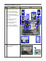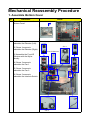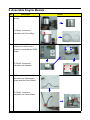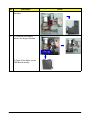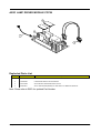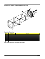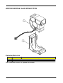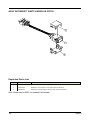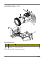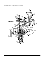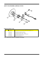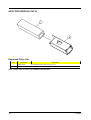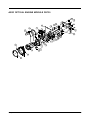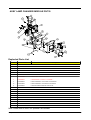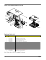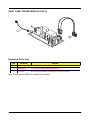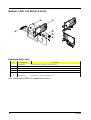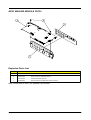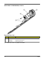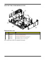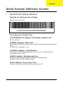
1
PD726 & PH730
Service Guide
Service guide files and updates are available
on the AIPG/CSD web; for more information,
please refer to http://csd.acer.com.tw
PRINTED IN TAIWAN
Revision History
Please refer to the table below for the updates made on PD726 & PH730 service guide.
Date
II
Chapter
Updates
Copyright
Copyright © 2005 by Acer Incorporated. All rights reserved. No part of this publication may be reproduced,
transmitted, transcribed, stored in a retrieval system, or translated into any language or computer language, in
any form or by any means, electronic, mechanical, magnetic, optical, chemical, manual or otherwise, without
the prior written permission of Acer Incorporated.
Disclaimer
The information in this guide is subject to change without notice.
Acer Incorporated makes no representations or warranties, either expressed or implied, with respect to the
contents hereof and specifically disclaims any warranties of merchantability or fitness for any particular
purpose. Any Acer Incorporated software described in this manual is sold or licensed "as is". Should the
programs prove defective following their purchase, the buyer (and not Acer Incorporated, its distributor, or its
dealer) assumes the entire cost of all necessary servicing, repair, and any incidental or consequential
damages resulting from any defect in the software.
Acer is a registered trademark of Acer Corporation.
Intel is a registered trademark of Intel Corporation.
Pentium 4 and Celeron are trademarks of Intel Corporation.
Other brand and product names are trademarks and/or registered trademarks of their respective holders.
III
Conventions
The following conventions are used in this manual:
IV
Screen messages
Denotes actual messages that appear
on screen.
NOTE
Gives bits and pieces of additional
information related to the current
topic.
WARNING
Alerts you to any damage that might
result from doing or not doing specific
actions.
CAUTION
Gives precautionary measures to
avoid possible hardware or software
problems.
IMPORTANT
Reminds you to do specific actions
relevant to the accomplishment of
procedures.
Preface
Before using this information and the product it supports, please read the following general information.
1.
This Service Guide provides you with all technical information relating to the BASIC CONFIGURATION
decided for Acer's "global" product offering. To better fit local market requirements and enhance product
competitiveness, your regional office MAY have decided to extend the functionality of a machine (e.g.
add-on card, modem, or extra memory capability). These LOCALIZED FEATURES will NOT be covered
in this generic service guide. In such cases, please contact your regional offices or the responsible
personnel/channel to provide you with further technical details.
2.
Please note WHEN ORDERING FRU PARTS, that you should check the most up-to-date information
available on your regional web or channel. If, for whatever reason, a part number change is made, it will
not be noted in the printed Service Guide. For ACER-AUTHORIZED SERVICE PROVIDERS, your Acer
office may have a DIFFERENT part number code to those given in the FRU list of this printed Service
Guide. You MUST use the list provided by your regional Acer office to order FRU parts for repair and
service of customer machines.
V
Table of Contents
Chapter 1 System Introduction
1
Technical Specification
Product Overview
System Block Diagram
1
3
7
Chapter 2 Firmware Upgrade
8
Equipment Needed
Installation Procedure
Firmware Upgrade Procedure
8
9
13
EDID Upgrade
16
EDID Introduction
Equipment Needed
Setup Procedure
EDID Key-in Procedure
16
16
17
17
Chapter 3 Mechanical Disassembly and Reassembly
Equipment Needed
General Information
Mechanical Disassembly Procedure
Mechanical Reassembly Procedure
Chapter 4 Troubleshooting
Equipment Needed
LED Lighting Message
Main Procedure
21
21
21
22
32
42
42
42
43
Function Test and Alignment Procedure
45
Product / Test Equipment / Test Condition
Guide to Entering Service Mode and Factory Reset
Inspection Procecdure
45
45
46
Chapter 5 Exploded Overview
Exploded Overview
Appendix Serial Number Definition System
I. Serial Number System Definition
II. PCBA Code Definition
III.The Different Parts PD726 / PH730
48
48
91
91
92
93
Chapter 1
System Introduction - PD726
Technical Specification
Item
Description
Dimensions (LxWxH)
350 x 282 x 118.75 mm
Weight
Approx. 7.7 lbs (3.5 Kg)
Tilt Angle
6 degree with elevator mechanism
Keystone correction
+/-16 degree (32 degree)
Lamp Door Projection
Lamp power supply shut off automatically when door is opened
Power Supply
- Universal AC 100-240V ~ 50-60Hz with PFC input
- 300W for OSRAM E21.8 (G2) Lamp @ normal operation
- Variance FAN speed control (Depends on temperature variant)
Projection Lens
[email protected], F/[email protected], 1.2X Manual Zoom Lens (WT41)
Throw Distance
1.2 - 12m (Mechanical Travel)
Brightness
- 3060 ANSI Lumens Typical @ Normal Mode
- 2450 ANSI Lumens minimum @ Normal Mode
Contrast
- 1200 : 1 Full White and Black (Minimum)
- 2000 : 1 Full White and Black (Typical)
Uniformity
- 70% Japan standard (Minimum)
- 85% Japan standard (Typical)
Temperature
Opterating : 5~35oC
Maximum Humidity
Operating : 5~35oC, 80%RH (Max.), non-condensing
Storage : -20~60oC, 80%RH (Max.), non-condensing
Acoustic noise level
Typical 35 dB(A) and maximum 37 dB(A) at 23+/- deg C for the full power (300W) mode
Typical 32 dB(A) and maximum 34 dB(A) at 23+/- deg C for the eco (250W) mode
Lamp Life
2000 hours min, 50% survival rate (Full Power Mode)
2500 hours min, 50% survival rate (Eco Mode)
Storage : -20~60oC
Operating : 0~2,500 ft for 5 oC~35oC
Altitude
2,500~5,000 ft for 5 oC~30oC
5,000~10,000 ft for 5 oC~25oC
Storage : 40,000 ft (Max.)
1
MTBF
Operating more than 12,000 hours (90% Confidence Level)
Resolution
1024(H) x 768(V)
Color Wheel
- Four segments: R(92) / G(83) / W(110) / B(75)
- 7200 rpm
DMD Chip
- 0.7” 12o LVDS XGA Digital Mirror Device
Chapter 1
System Introduction - PH730
Technical Specification
Item
Description
Dimensions (LxWxH)
350 x 282 x 118.75 mm
Weight
Approx. 7.7 lbs (3.5 Kg)
Tilt Angle
6 degree with elevator mechanism
Keystone correction
+/- 6 Degree
Lamp Door Projection
Lamp power supply shut off automatically when door is opened
Power Supply
- Universal AC 100-240V ~ 50-60Hz with PFC input
- 230W for OSRAM E20.5 Lamp @ normal operation
- Variance FAN speed control (Depends on temperature variant)
Projection Lens
f=22.25mm~26.69mm, F/2.5~2.8, 1.2X Manual Zoom Lens (YM10-M)
Throw Distance
1.5 - 10m (Mechanical Travel)
Brightness
- 1020 ANSI Lumens -- Typical
- 820 ANSI Lumens -- Engineering Minimum
Contrast
- 2500 : 1 Full White and Black -- Typical
- 1500 : 1 Full White and Black -- Engineering Minimum
Uniformity
- 75% Japan standard (Minimum)
- 85% Japan standard (Typical)
Temperature
Opterating : 5~35oC
Maximum Humidity
Operating : 5~35oC, 80%RH (Max.), non-condensing
Storage : -20~60oC, 80%RH (Max.), non-condensing
Acoustic noise level
Typical 32 dB(A) & maximum 34 dB(A) at 23+/-2 deg C for the full power (230W) mode
Typical 29 dB(A) & maximum 31 dB(A) at 23+/-2 deg C for the eco (180W) mode
Lamp Life
2000 hours min, 50% survival rate (Full Power Mode)
4000 hours min, 50% survival rate (Eco Mode)
Storage : -20~60oC
Operating : 0~2,500 ft for 5 oC~35oC
Altitude
2,500~5,000 ft for 5 oC~30oC
5,000~10,000 ft for 5 oC~25oC
Storage : 40,000 ft (Max.)
MTBF
Operating more than 12,000 hours (90% Confidence Level)
Resolution
1280(H) x 768(V)
Color Wheel
- Seven segments: B(47) / R(62) / G(56) / W(30) / B(47) / R(62) / G(56)
- 7200 rpm
DMD Chip
- 0.65” LVDS WXGA Digital Mirror Device
Chapter 1
2
Product Overview
Main Unit
Item
3
Description
1
Focus Ring / Zoom Ring
2
Zoom Lens
3
Elevator Button
4
Remote Control Receiver
5
Lens Cap Switch
6
Elevator Foot
7
Connection Ports
8
Power Socket
9
Control Panel
10
Detachable cable holder
Chapter 1
Control Panel
Item
Chapter 1
Description
1
Temp Indicator LED
2
Lamp Indicator LED
3
Power and Indicator LED (Power LED)
4
Source
5
Resync
6
Empowering Key
7
Menu
8
Back
9
Four Directional Select Keys (Keystone)
4
Connection Ports
Item
5
Description
1
USB Connector
2
HDMI Connector
3
DVI Input Connector
4
VGA Input Connector (PC Analog Signal)
5
Component Video Input Connector
6
S-Video Input Connector
7
RS232 Connector
8
KensingtonTM Lock Port
9
Power Socket
10
VGA Output Connector (Monitor Loop-through Output Connector)
11
Audio Input Connector
12
Composite Video Input Connector
Chapter 1
Connecting the Projector
Item
Chapter 1
Description
1
Power Cord
2
VGA Cable
3
Composite Video Cable
4
USB Cable
5
HDMI Cable (Optional Accessory)
6
S-Video Cable
7
Audio Cable Jack / Jack or Audio Cable Jack / RCA
8
DVI Cable (Optional Accessory)
9
3 RCA Component Cable
10
RS232 Cable (Optional Accessory)
6
CLOCK
GENERATION
FLASH BOOT/
EEPROM
RLDRAM
ADC
VGA
30
Video
Video
Decoder
8
PORT3
PORT2
PORT1
DVI/HDMI
LVDS DMD
I/F
DDP3020
ASIC
USB
RS232
Keypad
DAD1000
reset ASIC
IR Remote
WIRELESS I/F
CW index
DC-DC
1.5V
13V
uP8051
2.5V
5V
3.3V
POWER
SUPPLIES
CW
DRIVER
CW Motor
1.8V
Ballast
3.3V
3.3V ANALOG
5V
THERMAL SENSER
FANs
ballast control
Chapter 2
Firmware Upgrade
Equipment Needed
Software : (DDP 3020- USB)
- DLP Composer Lite (6.0)
- Firmware (PD726 & PH730)
Hardware :
Item
Photo
Item
Projector
(PD726 &
PH730)
USB Cable
Power Cord
PC or Laptop
Chapter2
Photo
8
Installation Procedure
DLP Composer Lite Setup Procedure
No
9
Step
Procedure
1
Execute
FW program
Choose
“DLP Composer Lite
v6.0 Setup” program.
2
Next
Click “Next” button.
3
Next
1. Reading the “License
Agreement” rules.
2. Choose “I accept and
agree to be bound by
all the terms and
conditions of this
License Agreement”
icon.
3. Click “Next” button.
4
Next
Click “Next” button.
Photo
Chapter 2
No
Step
Procedure
5
Next
1. Choose “All” icon.
2. Click “Next” button.
6
Next
Click “Next” button.
7
Processing
The program is executing “Initializing” status.
Chapter2
Photo
10
USB Driver Upgrade Procedure
No
1
Step
Set-up
Procedure
Photo
1. Hold on “Menu” button
and plug in Power
Cord while holding on
“Menu”.
2. Wait for about 5 secs.
3. Once Power, Lamp,
Temp LED lights up,
then, plug in USB
Cable into the
Projector.
(Note: The system fan
will operate in full speed.
The light will not function
as well.)
2
Execute
Program
Execute the C:\Program
files\DLP Composer
6.0\usbupdata.cmd
(Note: The “DLP Composer” program must be
closed first.)
3
11
Type any
key to
continue
Press any key to continue. Then, wait for about
1 minute.
Chapter 2
No
Step
4
Update
Successfully
In 1 minute, click “OK”.
The USB driver is updated successfully.
5
Device
Manager
1. Right click “My
computer” on the
desktop.
2. Select “Properties”
on the popup menu
to launch the “System
Properties” window.
3. Choose “Hardware”
and then click “Device
Manager”.
6
Ensure
“DDP3020”
& “WinDriver” are
properly
installed
Click “Jungo” to ensure
“Texas Instruments
DLPTM Processor”, then,
click “General” and
check if the Location is
“DDP3020” or not. Also,
“Windriver” are properly
installed. If not, repeart
Step 1~5.
Chapter2
Procedure
Photo
Device Manager
12
Firmware Upgrade Procedure
No
1
Step
Set-up
Procedure
Photo
1. Hold on “Menu” button and
plug in Power Cord while
holding on “Menu”.
2. Wait for about 5 secs.
3. Once Power, Lamp, Temp
LED lights up, plug in USB
Cable into the Projector.
(Note: The system fan will be
operated in full speed. The
light will not function as well.)
2
Set-up
Link PC USB and projector
3
Execute the “DLP
Compose(TM) Lite 6.0”.
4
Click “Edit” and “Preferences”.
1
2
5
1. Click “Library”.
2. The library path in
the default installation
directory is
C:\Program Files\DLP
Composer Lite 6.0
If not, press “Browse” to
select the right path.
6
1. Select “Edit\Prefer
ences\Communi
cations” and choose
“USB”.
2. Click “OK”.
1
USB
Vendor: 0x451
Product: 0x2000
2
13
OK
Chapter 2
No
7
Step
Procedure
1. Choose “Flash
Loader”
2. Click “Browse” to
search the firmware
file. (PD726 / PD730)
3. Select the item “Skip
Boot Loader Area
(load all but the first
64KB).”
4. Click “Reset Bus” to
erase the flash
memory.
(Note: If the error message “cannot open USB
driver - No projectors
found” appears, please
unplug the USB Cable
and replug, then check
Driver. Finally, re-do
4. Click “Reset Bus” to
erase the flash memory.)
8
Photo
1
2
3
4
Note:
1. If the firmware is
ready, click “Start
Download” to process
the firmware upgrade.
2. Click “Yes” to erase
the flash memory.
2
1
Chapter2
14
No
Step
9
Proceeding
10
11
Procedure
Photo
Proceeding Picture
1. When Firmware
Upgrade Process is
finished, the LED
power flashs.
2. Unplug USB Cable
and Power Cord.
Re-plug in Power
Cable.
Check
Firmware
Restart the unit and
enter the Service Mode
to check the Firmware
Version.
(For entering Service
Mode, please refer to
Chapter 4 Function Test
and Alignment Procedure.)
15
Chapter 2
EDID Upgrade
EDID Introduction
Extended Display Identification Data is a VESA standard data format that contains
basic information about a display device and its capabilities, including vendor information,
maximum image size, color characteristics, factory pre-set timings, frequency range limits,
and character strings for the model name and serial number.
The information is stored in the display and is used to communicate with the system
through a Display Data Channel (DDC), which sites between the display device and the PC
graphics adapter. The system uses this information for configuration purposes, so the unit
and system can work together.
Note:
If a display device has digital input ports, like DVI or HDMI, but without EDID in its
main board, the display device will show no image while the input source is digital signal.
Equipment Needed
Software:
- EDID Software (Generic V0.51)
- EDID Table (*.ini) -- PD726 or PH730
Hardware:
- V3 Fixture for EDID Key-in
(Fixture: JP3 must be closed)
Item
Photo
Item
RS-232
Cable
(F - M)
Power
Adapter for
Fixture
DVI Cable
Generic
Fixture
VGA Cable
Power Cord
Chapter2
Photo
16
Item
Photo
Item
Photo
One additional
monitor (for
PC
checking the program execution)
Projector
(PD726 /
PH730)
DVI-HDMI
Connector
Setup Procedure
No
Step
Procedure
Photo
1
Connect
All Ports
1. Power Adapter to Fixture JP1
2. Fixture P1 to PC COM1 Port
3. Fixture P2 to Projector Analog Port
4. Fixture P3 to Projector Digital Port
Adapter
To Digital Port
JP1
P3
P1
P2
RS-232 Cable
To Analog Port
2
Power On
Fixture
3
Notice: When installing the EDID in PD726 or PH730, please plug in power cord, but don’t power
on the unit.
Power on Fixture
EDID Key-In Procedure
No
Step
1
Execute
EDID
Program.
Click on “EDID” to execute EDID Program.
2
Choose
Model
1. In the Port Selection
Bar, please choose
the Port that you use.
Ex: If you use “COM
1”, choose COM 1 in
the Port selection.
2. Click on “Model”.
3. Choose the EDID that
responses to the
model that you
choose.
17
Procedure
Photo
1
2
3
Chapter 2
No
3
Step
Key in
Serial
Number
Procedure
1. Key in the Serial
Number into the
Barcode blank space.
2. In “Write Source
Select”, make a check
in “Analog” and
“Digital”.
3. Click “Program”.
Photo
1
3
2
4
Change
Cable to
Analog
“Please change the
Cable to Analog” message is shown on the
screen, then click “OK”.
(Note: “RUN” message will appear on the
screen.)
5
Change
Cable to
Digital
“Please change the
Cable to Digital” message is shown on the
screen, then click “OK”.
(Note: “RUN” message will appear on the
screen.)
6
Chapter2
Finished
When the EDID program
is completed, the message, “OK”, will appear
on the screen.
18
No
7
8
Step
Install
HDMI
EDID
Change
Cable to
Digital
Procedure
For the HDMI EDID
Installation:
1. Plug “DVI-HDMI
Connector” in the
HDMI port.
2. Connect the DVI
Cable.
3. Once the Cable is
connected, please
follow the step 3 and
choose the Digital
pattern to execute the
EDID installation.
Photo
1
3
2
“Please change the
Cable to Digital” message is shown on the
screen, then click “OK”.
(Note: “RUN” message will appear on the
screen.)
9
19
Finished
When the EDID program
is completed, the message, “OK”, will appear
on the screen.
Chapter 2
No
Step
Procedure
10
Check
the whole
process
1. In the “Read Item”
Selections, choose
the Port that you use.
Ex: If you use the
Analog Port, choose
“Analog” in the “Read
Item”.
2. Click on “Read” to
read EDID
information.
3. The “EDID
Informations” will
show the result.
Photo
3
2
4
1
(Note: After pressing “Read”, if the code
in the Serial Blank is
scrambled, please make
a check in “Trans”.)
4. Click “Reset” to do the
next unit or “Exit” to
close the EDID
program.
Note
PS.
Both Analog and Digital are needed to be
checked.
Chapter2
20
Chapter 3
Mechanical Disassembly & Reassembly
This section provides disassembly & Reassembly procedures for PD726 & PH730 DMD
Projector. Before you begin any of these procedures, be sure to turn off the power, computer
system, and other attached devices; then disconnect the power cable from the electrical
outlet. Moreover, when you disassemble the projector, be sure to put the screws in a safe
place and separate them according to their category.
Equipment Needed
Item
Photo
Item
Philips (+) : 107
Philips (+) : 102
Philips (+) : 101
Hex Screw :
5mm
Screw Bit :
6.0 X 100
Side Cutter
Pliers
Long Nose
Pliers
Tweezers
Photo
Hexagon Keys
General Information
Before You Begin
Before proceeding with the disassembly procedure, make sure that you do the following
procedures:
1. Turn off the power of the system and all the peripherals.
2. Unplug the AC adapter and all power and signal cables from the system.
3. Anti-static wrist strap.
21
Chapter 3
Mechanical Disassembly Procedure
1. Remove Lamp Module
No
Procedure
1 Loosen 2 tenons to remove
the Lamp Cover.
2
Photo
Unscrew 3 screws to remove
the Lamp Module.
Chapter 3
22
2. Remove and disassemble Top Cover Module
No
Procedure
1 Unscrew 6 screws in the
Bottom Cover, then, unplug 1
IR Receiver wire and 1 FPC
connector to remove Top
Cover Module.
23
2
Remove Keypad Board:
(1) Unscrew 4 screw and
unplug 1 FPC to remove the
Keypad Board.
(2) Separate all the keypad
components.
3
IR Receiver:
Tear off the mylar to remove
the IR Receiver directly.
Photo
Chapter 3
No
Procedure
4 Remove Assy Manual Lens
Cap Module:
(1) Remove 4 screws to
remove the Lens Cap Module.
Photo
(2) Unscrew 2 screws in the
front & 2 screws in the back to
remove the Lens Cap.
(3) Unscrew 1 screw to
disassemble the Lens Cap;
then, loosen 6 tenons to
separate the Lens Cap
Module.
Chapter 3
24
3. Remove Main Board & Audio Board
No
Procedure
1 Unscrew 5 screws, unplug 10
connectors and 1 connector
in the Bottom; then, unscrew
6 hex screws to remove the
Main Board & Audio Board.
25
Photo
Chapter 3
4. Remove IO Cover and Side Covers (Speakers) / LVPS
No
Procedure
1 Remove the IO Cover / Side
Covers with Speakers directly.
(Right Cover & Left Cover)
2
Photo
Remove LVPS:
(1) Unscrew 6 screws and
unplug 2 wires
(2) Unplug 3 connectors
to remove the LVPS.
Chapter 3
26
5. Remove Thermal Switch / Light Cut / Air Duct
No
Procedure
1 (1) Unscrew 1 screw to
remove the Thermal Switch.
Photo
(2) Unscrew 5 screws to
remove the Light Cut.
2
27
Unscrew 1 screw to remove
the Air Duct.
Chapter 3
6. Remove Lamp Driver / Fan
No
Procedure
1 Remove Lamp Driver:
(1) Unscrew 4 screws
(2) Unscrew 2 screws and
unplug 3 connectors to
remove the Lamp Driver.
2
Photo
Remove Fan Module:
(1) Unscrew 2 screws to
remove the Fan Module.
(2) Unscrew 4 screws to
separate the Fan Module.
Chapter 3
28
7. Remove Engine Module
No
Procedure
1 (1) Unscrew 4 screws to
remove the Engine Module.
Photo
(2) Take off the Mylar on the
DMD Board directly.
2
Unscrew 5 screws to remove
the Mylar.
3
(1) Unscrew 1 screw to
remove the Color Wheel.
(2) Unscrew 1 screw to
remove the Photosensor
Board.
Note: It is suggested to use
the Long Nose Pliers to fasten
one side of the Color Wheel
(with the photosensor Board)
and unscrew 1 screw to
separate the Color Wheel and
Photosensor Board.
29
Chapter 3
No
Procedure
4 (1) Unscrew 4 screws to
remove the Heatsink.
Photo
(2) Unscrew 4 screws to
separate the DMD Board and
disassemble the components.
5
(1) Unscrew 3 screws to
remove the Focus Ring.
(2) Take the Zoom Ring off
directly.
Chapter 3
30
8. Remove Bottom Cover
No
Procedure
1 (1) Unscrew 4 screws to
remove the Elevator (Left).
(2) Unscrew 4 screws to
remove the Elevator (Right).
Photo
Elevator (Right)
Elevator (Left)
Fan 1
Front IR Receiver
(3) Tear off the Mylar and
remove the Front IR Receiver
directly.
(4) Unscrew 3 screws to
remove the Fan 1.
(5) Unscrew 2 screws to
remove the Fan 2.
(6) Unscrew 2 screws to
remove the Interlock Switch.
Fan 2
2
31
Interlock Switch
Unscrew 9 hex spacers
and separate them from the
Bottom Cover.
Chapter 3
Mechanical Reassembly Procedure
1. Assemble Bottom Cover
No
Procedure
1 Screw 9 hex spacers to the
Bottom Cover.
2
(1) Screw 4 screws to
assemble the Elevator (Left).
(2) Screw 4 screws to
assemble the Elevator (Right).
Photo
Elevator (Right)
Elevator (Left)
Fan 1
Front IR Receiver
(3) Assemble the Front IR
Receiver with the Mylar
directly.
(4) Screw 3 screws to
assemble the Fan 1.
(5) Screw 2 screws to
assemble the Fan 2.
(6) Screw 2 screws to
assemble the Interlock Switch.
Fan 2
Chapter 3
Interlock Switch
32
2. Assemble Engine Module
No
Procedure
1 (1) Assemble the Zoom Ring
directly.
Photo
(2) Screw 3 screws to
assemble the Focus Ring.
2
(1) Assemble all the
components and screw 4
screws to assemble the DMD
Board.
(2) Screw 4 screws to
assemble the Heatsink.
3
(1) Screw 1 screw to
assemble the Photosensor
Board with the Color Wheel.
(2) Screw 1 screw to
assemble the Color Wheel.
33
Chapter 3
No
Procedure
4 Unscrew 5 screws to remove
the Mylar.
5
Photo
(1) Unscrew 4 screws to
remove the Engine Module.
(2) Take off the Mylar on the
DMD Board directly.
Chapter 3
34
3. Assemble Fan / Lamp Driver
No
Procedure
1 Assemble Fan Module:
(1) Screw 4 screws to
assemble the Fan Module
components.
(2) Screw 2 screws to
assemble the Fan Module.
2
35
Photo
Assemble Lamp Driver:
(1) Plug in 3 connectors and
screw 2 screws.
(2) Screw 4 screws to
assemble the Lamp Driver.
Chapter 3
4. Assemble Air Duct / Light Cut / Thermal Switch
No
Procedure
1 Screw 1 screw to assemble
the Air Duct.
2
Photo
(1) Screw 5 screws to
assemble the Light Cut.
(1) Screw 1 screw to
assemble the Thermal Switch.
Chapter 3
36
5. Assemble LVPS / IO Cover & Side Covers (Speakers)
No
Procedure
2 Assemble LVPS:
(1) Plug in 3 connectors.
(2) Plug in 2 wires and screw
6 screws to assemble the
LVPS.
1
37
Photo
Assemble the IO Cover / Side
Covers with Speakers directly.
(Right Cover & Left Cover)
Chapter 3
6. Assemble Main Board & Audio Board
No
Procedure
1 Screw 6 hex screws in the
Bottom Cover; then, plug in 10
connectors and 1 connector
in the Bottom and screw 5
screws to assemble the Main
Board & Audio Board.
Chapter 3
Photo
38
7. Assemble Top Cover Module
No
Procedure
1 Assemble Assy Manual Lens
Cap Module:
(1) Fasten 6 tenons and screw
1 screw to assemble the Lens
Cap.
Photo
(2) Screw 2 screws in the
front & 2 screws in the back to
assemble the Lens Cap.
(3) Screw 4 screws to
assemble the Lens Cap
Module.
2
39
IR Receiver:
Put on the mylar to assemble
the IR Receiver directly.
Chapter 3
No
Procedure
3 Assemble Keypad Board:
(1) Assemble all the keypad
components.
(2) Plug in 1 FPCU and screw
4 screw to assemble the
Keypad Board.
4
Photo
Plug in 1 IR Receiver wire and
1 FPC connector; then, screw
6 screws in the Bottom Cover
to assemble the Top Cover
Module.
Chapter 3
40
8. Assemble Lamp Module
No
Procedure
1 Screw 3 screws to assemble
the Lamp Module.
2
41
Photo
Fasten 2 tenons to assemble
the Lamp Cover.
Chapter 3
Chapter 4
Troubleshooting
Equipment Needed
- PC or Pattern Generator
- DVD Player (Video, S-Video, Audio)
- Quantum Data 802B or CHROMA 2327
LED Lighting Message
Lamp LED
Red
Temp LED
Red
Power LED orange
Flash ON to OFF 100ms
Flash ON to OFF 100ms
Flash ON to OFF 100ms
Standby
OFF
OFF
Blinking
1 sec ON / 1 sec OFF
Power button ON
OFF
OFF
ON
Message
Power Plug
Power button OFF:
Cooling State I
OFF
OFF
Blinking
0.5 sec ON/ 0.5 sec OFF
Power button OFF:
Cooling state II
OFF
OFF
Blinking
1 sec ON / 1 sec OFF
Power button OFF:
Cooling completed
OFF
OFF
Blinking
1 sec ON / 1 sec OFF
(Fan Off)
Fan lock error
OSD shows red
“Projector Overheated”
OFF
0.5 sec On, 0.5 sec Off
flashing for 30sec
OFF
Lamp error
(Lamp, ballast)
ON
OFF
OFF
Color Wheel fail
ON
ON
OFF
BurnIn Lamp ON
OFF
OFF
ON
BurnIn Lamp OFF
OFF
OFF
Blinking
1 sec ON / 1 sec OFF
BurnIn Random
delay time
ON
ON
OFF
**Power OFF:
(A) Cooling state I
(B) Cooling state II
: Power orange LED blinking 0.5sec ON / 0.5sec OFF.
: Power orange LED Blinking 1sec ON / 1sec OFF, But FAN ON.
(Can be powered ON via Power key during this state).
(C) Cooling complete : Power orange LED Blinking 1sec ON / 1sec OFF, FAN OFF.
(Entered StandBy Mode)
Chapter 4
42
Main Procedure
No
43
Symptom
Procedure
1
No Power
- Ensure the Power Cord and AC Power Outlet are securely connected
- Check Lamp Cover and Interrupt Switch
- Ensure all connectors are securely connected and aren’t broken
- Check DC-DC
- Check Ballast
- Check Main Board
2
Auto Shut Down
- Check LED Status
a. Lamp LED Light
- Check Lamp
- Check Lamp Driver
- Check Main Board
b. Temp LED Light
- Check Thermal Sensor
- Check Thermal Switch
- Check Fan
c. Color Wheel
- Check Color Wheel
- Check Photo Sensor
d. No Power
- Refer to “No Power” troubleshooting
3
No Image
- Ensure the Signal Cable and Source work as well
(If you connect multiple sources at the same time, use the “Source”
button on the control panel to swtich)
- Ensure all connectors are securely connected and aren’t broken
- Check Main Board
- Check DMD Board
- Check Color Wheel
- Check DMD Chip
- Check Engine Module
4
No Light On
- Ensure all connectors are securely connected and aren’t broken
- Check Lamp Module
- Check DC-DC
- Check Ballast
- Check Main Board
5
Mechanical Noise
- Check Color Wheel
- Check Fan Module
6
Line Bar / Line
Defect
- Sometimes it’s because of the DMD Chip and the DMD Board did
not assemble properly
- Check DMD Board
- Check DMD Chip
- Check Main Board
Chapter 4
No
Symptom
Procedure
7
Image Flicker
- Do “Reset” of the OSD Menu
- Ensure the Signal Cable and Source work as well
- Check Lamp Module
- Check Color Wheel
- Check DMD Board
- Check Main Board
8
Color Abnormal
- Do “Reset” of the OSD Menu
- Adjust Color Wheel Index
- Check Main Board
- Check DMD Board
- Check Color Wheel
9
Poor Uniformity /
Shadow
- Ensure the Projection Screen without dirt
- Ensure the Projection Lens is clean
- Ensure the Brightness is within spec.
(Replace the Lamp if the Brightness is less than spec.)
- Check Engine Module
10
Dead Pixel / Dust
(Out of spec.)
- Ensure the Projection Screen without dirt
- Ensure the Projection Lens is clean
- Clean DMD Chip and Engine Module
- Check DMD Chip
- Check Engine Module
11
Garbage Image
- Ensure the Signal Cable and Source work as well
- Check Main Board
- Check DMD Board
12
Remote Controll
or Control Panel
Failed
- Remote Control
a. Check Battery
b. Check Remote Control
c. IR Receiver
- Control Panel
a. Check FPC
b. Check Keypad
c. Check Main Board
13
Function Abnormal
- Do “Reset” of the OSD Menu
- Check Main Board
- Check DMD Board
Chapter 4
44
Chapter 5
Exploded Overview
EXPLODED OVERVIEW (D.C PD726)
Chapter 5
48
Exploded Parts List
Item
Part Number
Description
1
70.83N01G001
ASSY ENGINE MODULE PD726
2
70.83N07G001
ASSY LAMP CHANGER MODULE PD726
3
70.83N09G001
ASSY TOP COVER MODULE PD726
4
70.83N10G001
ASSY BOTTOM HOUSING MODULE PD726
5
51.83N11G001
ELEVATOR FOOT PC MN-3600H PD726
6
52.83N01G001
ELEVATOR FOOT SILICON RUBBER PD726
7
51.83N24G001
LAMP COVER PC MN-3600H PD726
8
61.89641G001
LAMP COVER AL FOIL 0.1t EP759/PD726
9
70.83N15G001
ASSY BLOWER FAN 60*25 MODULE PD726
10
75.83N09G001
ASSY FAN GUIDER COVER MODULE PD726
11
85.005AGG408
SCREW HEX I/O #4-40 H4*L8 NI NYLOK
12
85.1A123G060
SCREW PAN MECH M3*6 NI
13
85.TA326G070
SCREW CAP TAP M2.6*7 WASHER BLACK
14
85.WA123G060
SCREW PAN TAP M3*6 Ni
15
85.WD123G080
SCREW PAN TAP 3*8 W/WASHER Ni
16
85.1A123G080
PAN SCREW M3*8 FOR YM-64 FRONT CELL & SP
17
52.89611G001
DUCT RUBBER EP759/PD726
18
85.0A323G060
SCREW P/F MECH M3*6 BLACK
19
85.1A126G040
SCREW PAN MECH M2.6*4 Ni
20
85.WA123G080
SCREW PAN TAP M3*8 Ni
21
70.83N23G001
ASSY MAIN-BD MODULE PD726
22
43.87301G001
90c, TI THERMAL SWITCH
Note: Please refer to RSPL for updated Part Number.
49
Chapter 5
ASSY ENGINE MODULE PD726
Exploded Parts List
Item
Part Number
Description
1
70.83N04G001
ASSY OPTICAL ENGINE MODULE PD726
2
70.83N02G001
ASSY ENGINE BASE MODULE PD726
3
85.1A126G080
SCREW PAN MECH M2.6*8 Ni
Note: Please refer to RSPL for updated Part Number.
Chapter 5
50
ASSY ENGINE BASE MODULE PD726
51
Chapter 5
Exploded Parts List
Item
Part Number
Description
1
23.89602G001
POLYGON MIRROR (t1.1mm)
2
23.89620G001
CONDENSER 1 X26mm BK7 SPHERE
3
23.89620G002
CONDENSER 2 X26mm BK7 SPHERE
4
51.89614G001
ENGINE BASE BMC EP759/PD726
5
51.89637G001
ENGINE MIRROR ANTI LIGHT MYLAR EP759/PD726
6
52.85808G001
PORON-LENS BLACK XB31
7
52.89625G001
LAMP HOUSING STEAMTIGHT TOP F12 3.2t EP759/PD726
8
52.89626G001
LAMP HOUSING STEAMTIGHT SIDE F12 1.6t EP759/PD726
9
61.89602G001
LAMP HOUSING Mg ALLOY AZ91D EP759
10
61.89611G001
MIRROR SPRING PLATE SUS301 0.25t EP759/PD726
11
61.89617G001
ROD BRACKET AL 0.6t EP759/PD726
12
61.89621G001
ROD SPRING SUS301 0.25t EP759/PD726
13
70.83N03G001
ASSY COLOR WHEEL MODULE PD726
14
70.83N20G001
ASSY ROD MODULE PD726
15
70.83N21G001
ASSY RELAY LENS MODULE PD726
16
85.1A122G060
SCREW PAN MECH M2*6 Ni
17
85.1A126G040
SCREW PAN MECH M2.6*4 Ni
18
85.1A126G080
SCREW PAN MECH M2.6*8 Ni
Note: Please refer to RSPL for updated Part Number.
Chapter 5
52
ASSY COLOR WHEEL MODULE PD726
Exploded Parts List
Item
Part Number
Description
1
23.83N19G001
COLOR WHEEL X48mm R92/G83/W110/B75 SLEEVE BEARING CW; YO
2
52.89606G001
COLOR WHEEL RUBBER EP759/PD726
3
61.89511G001
COLOR WHEEL SCREW 4100MP " GREEN"
4
61.89608G001
COLOR WHEEL BRACKET SECC 1.2t EP759/PD726
5
80.83N06G001
PCBA PHOTO SENSOR BD PD726
6
85.1A126G040
SCREW PAN MECH M2.6*4 Ni
Note: Please refer to RSPL for updated Part Number.
53
Chapter 5
ASSY OPTICAL ENGINE MODULE PD726
Chapter 5
54
Exploded Parts List
Item
1
Part Number
Description
52.89633G001
THERMAL PAD FOR DMD HEAT SINK 17*13*0.3mm, Fujipoly GR-HM
2
00.83N02G001
BARE PCB L:8 DMD BD PD726
3
11.009F0G006
CNNT F 203P FOR 0.55" SVGA LGA DMD SOCKET;TELEDYNE "GREEN"
4
23.80J01G001
DLP 0.7"XGA ZOOM PROJECTION LENS
5
48.83N01G001
DMD 0.7 XGA 12X LVDS TYPE A
6
51.83N19G001
FOCUS RING PD726
7
51.83N22G001
FOCUS RING COVER PD726
8
51.89627G001
DMD INSULATION MYLAR EP759/PD726
9
51.89628G001
ZOOM STOP RING PC+ABS C6200 EP759/PD726
10
52.87110G001
RUBBER CAP RUBBER PD726
11
52.89613G001
ENGINE SEAL RUBBER EP759/PD726
12
52.89627G001
DMD SEAL RUBBER F12 3.2t EP759
13
61.85926G001
COLOR WHEEL SHOULDER SCREW SB21
14
61.89605G001
DMD BACKER PLATE AL 3.0t EP759/PD726
15
61.89626G001
HEATSINK SCREW EP759
16
61.89627G011
ENGINE COVER AZ91D EP759/PD726 "FOXCONN"
17
61.89630G001
HEATSINK SPRING EP759/PD726
18
61.89631G001
MASK BRACKET AL 0.8t EP759/PD726
19
61.89643G001
DMD MASK PLATE SUS301 0.15t EP759
20
70.83N05G001
ASSY DMD HEATSINK MODULE PD726
21
70.81N35G001
ASSY OFFRAY HEATSINK MODULE PD725P/PD723P/PD726
22
75.83N02G001
ASSY ZOOM RING MODULE PD726
23
85.1A123G080
PAN SCREW M3*8 FOR YM-64 FRONT CELL & SP
24
85.1A126G080
SCREW PAN MECH M2.6*8 Ni
25
85.1A626G040
SCREW PAN MECH M2.6*4 BLACK NYLOK
26
85.4A121G080
SCREW FLAT HEAD TAP M1.7*8 Ni BLACK
Note: Please refer to RSPL for updated Part Number.
55
Chapter 5
ASSY LAMP CHANGER MODULE PD726
Exploded Parts List
Item
Part Number
Description
1
23.89610G002
BOROFLOAT UV-IR SQUARE t2.75mm
2
23.83N15G001
OSRAM LAMP E21.8 1.3mm ARC 300W G2
3
61.89633G001
LAMP MECH GREEN EP759/PD726
4
51.89621G012
LAMP CHANGER TILT 20 PPS+40%GF EP759/PD726
5
61.89603G021
LAMP MESH HOLDER TILT 20 AZ91D EP759/PD726 - FOXCONN
6
61.89606G001
UV-IR BRACKET SPRING SUS301 0.3t EP759/PD726
7
61.89618G002
LAMP CLIP HOLDER SUS301 0.25t EP759/PD726
8
61.89619G001
LAMP CLIP PUSH SUS301 0.25t EP759/PD726
9
61.89636G001
LAMP CHANGER AL FOIL FRONT EP759/PD726
10
61.89637G001
LAMP CHANGER AL FOIL BACK EP759/PD726
11
61.89639G001
LAMP EXCHANGE HANDLER FOR EP759
12
61.83N04G001
BLOWER DUCT-1 PD726
13
85.0A122G030
SCREW DOUBLE FLAT MECH M2*3Ni
14
85.1A122G040
SCREW PAN MECH M2*4 Ni
15
85.1A122G050
SCREW PAN MECH M2*5 Ni
16
85.4A326G060
SCREW FLAT MECH M2.6*6 BLACK
17
61.00018G002
LOCK SCREW PAN MECH M3*8.5-3.5 BLACK
Note: Please refer to RSPL for updated Part Number.
Chapter 5
56
ASSY TOP COVER MODULE PD726
Exploded Parts List
Item
Part Number
Description
1
75.83N03G001
ASSY TOP COVER PD726
2
51.83N03G001
KEYPAD MAIN BUTTON PC PD726
3
51.83N04G001
KEYPAD MIDDLE BUTTON PC PD726
4
80.83N04G001
PCBA KEY BOARD ASSY PD726
5
42.83N01G001
CABLE FFC 20P 0.5mm L=100mm PD726
6
51.83N23G001
KEYPAD RIGHT BUTTON PC PD726
7
51.83N23G002
KEYPAD LEFT BUTTON PC PD726
8
85.1D122G030
SCREW PAN MECH M2*3 Ni(W/WSHER X5.0)
9
80.83N05G001
PCBA IR SENSOR BOARD FOR PD726
10
51.83N02G001
LENS AREA COVER PC MN-3600H PD726
11
85.C0023G050
SCREW INNER HEXAGON SUS M3*L5 PD726
12
51.82U06G001
SUNSHAD FOR FRONT IR FRPP 0.125t TDP-P8
13
70.83N22G001
ASSY MANUAL LENS CAP MODULE PD726
14
85.4A326G060
SCREW FLAT MECH M2.6*6 BLACK
Note: Please refer to RSPL for updated Part Number.
57
Chapter 5
ASSY BOTTOM HOUSING MODULE PD726
Chapter 5
58
Exploded Parts List
Item
Part Number
Description
1
85.1A123G060
SCREW PAN MECH M3*6 NI
2
85.WA123G060
SCREW PAN TAP M3*6 Ni
3
80.83405G001
PCBA THERMAL SENSOR BD EzPro 730/735 ID=90
4
70.83N11G001
ASSY BOTTOM COVER MODULE PD726
5
70.83N12G001
ASSY LVPS MODULE PD726
6
70.83N13G001
ASSY LAMP DRIVER MODULE PD726
7
70.83N14G001
ASSY AXIAL FAN 92*25 MODULE PD726
8
86.03123G035
HEX CAP HEAD NUT M3*0.5P L3.5
9
75.83N05G001
ASSY PRE ELEVATOR MODULE PD726
10
85.TA326G070
SCREW CAP TAP M2.6*7 WASHER BLACK
11
85.WD123G080
SCREW PAN TAP 3*8 W/WASHER Ni
12
80.83N05G001
PCBA IR SENSOR BOARD FOR PD72
13
52.89601G001
ADJUST FOOT RUBBER EP910
14
52.89605G001
REAR FOOT RUBBER EP759/PD726
15
75.83N06G001
ASSY WIND TUNNEL MODULE PD726
16
70.83N16G001
ASSY INTERRUPT SWITCH MODULE PD726
17
51.00075G001
WIRE MOUNTS PG-FW-4D PD120
18
70.83N17G001
ASSY BLOWER FAN 50*20 MODULE PD726
19
52.89631G002
LAMP TO BTM INSULATOR RUBBER EP759/PD726
20
51.82U06G001
SUNSHAD FOR FRONT IR FRPP 0.125t TDP-P8
Note: Please refer to RSPL for updated Part Number.
59
Chapter 5
ASSY BOTTOM COVER MODULE PD726
Exploded Parts List
Item
Part Number
Description
1
75.83N04G001
ASSY BOTTOM COVER PD726
2
70.83N18G001
ASSY LEFT COVER MODULE PD726
3
70.83N19G001
ASSY RIGHT COVER MODULE PD726
4
52.89610G001
STEAMTIGHT NEAR WIND TUNNEL F12 EP759/PD726
5
61.89634G001
HEX SPACER M3 H=23mm L=6mm BRASS PD726
6
61.88511G001
HEX SPACER M3 H=52mm L=4mm AL PD726
Note: Please refer to RSPL for updated Part Number.
Chapter 5
60
ASSY LVPS MODULE PD726
Exploded Parts List
Item
Part Number
Description
1
42.89611G001
W.A. 3P #20 250mm LAMP DRIVER TO LVPS EP759/PD726
2
75.82B28G001
BUY ASSY BRACKET LVPS HOLDER 5100MP
3
61.82K16G001
SCREW M4 AC GROUNDING
4
75.83N10G001
ASSY LVPS QUASAR 300W PD726
5
42.83N03G001
W.A. MAIN BD TO LVPS PD726/PH730
Note: Please refer to RSPL for updated Part Number.
61
Chapter 5
ASSY LAMP DRIVER MODULE PD726
Exploded Parts List
Item
Part Number
Description
1
42.89608G001
W.A. 5P #28 140mm LAMP DRIVER TO MAIN BD EP910
2
51.89639G001
LAMP DRIVER EMI MYLAR EP759/PD726
3
75.80L01G003
ASSY OSRAM LAMP DRIVER 300W TYPE-04
4
76.89601G011
ASSY LAMP DRIVER(OSRAM) TO LAMP SMK W.A. GREEN EP759/PD726
Note: Please refer to RSPL for updated Part Number.
Chapter 5
62
ASSY AXIAL FAN 92*25 MODULE PD726/PH730
Exploded Parts List
Item
Part Number
Description
1
49.83C04G001
SUNON 9225 AXIAL FAN/KDE1209PTBX
2
52.83N05G001
100X32 FAN STEAMTIGHT RUBBER PD726
3
52.L1308G002
FAN 9225 RUBBER BOTTOM H76/PD726
4
52.L1309G001
FAN 9225 RUBBER TOP H76/PD726
5
61.86633G001
PANAFLO 92*25 AL FOIL H76/PD726
6
61.83N15G001
100X32 FAN HOLDER PD726
7
61.L1322G001
SCREW FOR 9225 FAN H76
Note: Please refer to RSPL for updated Part Number.
63
Chapter 5
ASSY BLOWER FAN 60x25 MODULE PD726
Exploded Parts List
Item
Part Number
Description
1
49.83N01G001
SUNON, GB1206PTV2-AY, 60*60*25 BLOWER
2
52.89503G001
FAN 595925 SILICON RUBBER 4100MP/PD726
Note: Please refer to RSPL for updated Part Number.
Chapter 5
64
ASSY INTERRUPT SWITCH MODULE PD726
Exploded Parts List
Item
Part Number
Description
1
43.889601G001
INTERRUPT SWITCH LC-8306 EP759/PD726
2
51.89623G001
INTERRUPT S/W HOLDER TOP PC+ABS C6200 EP759/PD726
3
51.89624G001
INTERRUPT S/W HOLDER BOTTOM PC+ABS C6200 EP759/PD726
Note: Please refer to RSPL for updated Part Number.
65
Chapter 5
ASSY BLOWER FAN 50x20 MODULE PD726
Exploded Parts List
Item
Part Number
Description
1
49.83N02G001
SUNON, GB1205PKV4-AY, 50*50*20 BLOWER
2
52.89603G001
BLOWER FAN 50*20 RUBBER EP759/PD726
Note: Please refer to RSPL for updated Part Number.
Chapter 5
66
ASSY LEFT COVER MODULE PD726
Exploded Parts List
Item
Part Number
Description
1
75.83N07G001
ASSY LEFT COVER PD726
2
52.89608G001
SPEAKER SPONGE CR 2t EP759/PD726
3
49.83N03G001
SPEAKER 8ohm 3W PD726/PH730
4
85.1A123G060
SCREW PAN MECH M3*6 NI
Note: Please refer to RSPL for updated Part Number.
67
Chapter 5
ASSY RIGHT COVER MODULE PD726
Exploded Parts List
Item
Part Number
Description
1
75.83N08G001
ASSY RIGHT COVER PD726
2
52.89608G001
SPEAKER SPONGE CR 2t EP759/PD726
3
49.83N03G001
SPEAKER 8ohm 3W PD726/PH730
4
85.1A123G060
SCREW PAN MECH M3*6 NI
Note: Please refer to RSPL for updated Part Number.
Chapter 5
68
ASSY ROD MODULE PD726
Exploded Parts List
Item
Part Number
Description
1
23.89617G002
HOLLOW ROD 6.2mm*4.6mm*31.3mm(t1.1mm)
2
61.89620G001
ROD HOLDER SUS301 0.2t EP759/PD726
Note: Please refer to RSPL for updated Part Number.
69
Chapter 5
ASSY RELAY LENS MODULE PD726
Exploded Parts List
Item
Part Number
Description
1
23.89606G001
ASPHERIC RELAY LENS GREEN DESIGN EP759
2
51.89625G001
RELAY HOLDER PPS+40%GF EP759/PD726
3
61.89612G001
RELAY SPRING PLATE SUS301 0.4t EP759/PD726
4
85.WA126G040
SCREW PAN TAP M2.6*4 Ni
5
61.89644G002
STRAY LIGHT MASK EP723P
Note: Please refer to RSPL for updated Part Number.
Chapter 5
70
MANUAL LENS CAP MODULE PD726
Exploded Parts List
Item
Part Number
Description
1
51.83N08G001
ADJUST BUTTON COVER PC MN-3600H PD726
2
51.83N07G001
LENSCAP ADJUST BUTTON PC MN-3600H PD726
3
61.83N02G001
MANUAL LENS CAP AL-HAIRLINE PD726
4
61.83N10G001
LENS CAP SPRING SUS PD726
5
61.83N16G001
LENS CAP CONNECTING-ROD AL PD726
6
85.TA122G030
SCREW CAP TAP M2*L3 NI WASHER D7.5
Note: Please refer to RSPL for updated Part Number.
71
Chapter 5
ASSY MAIN-BD MODULE PD726
Exploded Parts List
Item
Part Number
Description
1
75.83N01G001
ASSY MAIN BOARD MODULE PD726
2
51.83N17G001
BACK COVER PC MN-3600H PD726
3
85.1A123G060
SCREW PAN MECH M3*6 NI
4
51.83N27G001
BACK I/O SHEET NO WIRELESS MODULE PD726
Note: Please refer to RSPL for updated Part Number.
Chapter 5
72
EXPLODED OVERVIEW D.C PH730
73
Chapter 5
Exploded Parts List
Item
Part Number
Description
1
70.83N01G001
ASSY ENGINE MODULE PD726
2
70.83N07G001
ASSY LAMP CHANGER MODULE PD726
3
70.83N09G001
ASSY TOP COVER MODULE PD726
4
70.83N10G001
ASSY BOTTOM HOUSING MODULE PD726
5
51.83N11G001
ELEVATOR FOOT PC MN-3600H PD726
6
52.83N01G001
ELEVATOR FOOT SILICON RUBBER PD726
7
51.83N24G001
LAMP COVER PC MN-3600H PD726
8
61.89641G001
LAMP COVER AL FOIL 0.1t EP759/PD726
9
70.83N15G001
ASSY BLOWER FAN 60*25 MODULE PD726
10
75.83N09G001
ASSY FAN GUIDER COVER MODULE PD726
11
85.005AGG408
SCREW HEX I/O #4-40 H4*L8 NI NYLOK
12
85.1A123G060
SCREW PAN MECH M3*6 NI
13
85.TA326G070
SCREW CAP TAP M2.6*7 WASHER BLACK
14
85.WA123G060
SCREW PAN TAP M3*6 Ni
15
85.WD123G080
SCREW PAN TAP 3*8 W/WASHER Ni
16
85.1A123G080
PAN SCREW M3*8 FOR YM-64 FRONT CELL & SP
17
52.89611G001
DUCT RUBBER EP759/PD726
18
85.0A323G060
SCREW P/F MECH M3*6 BLACK
19
85.1A126G040
SCREW PAN MECH M2.6*4 Ni
20
85.WA123G080
SCREW PAN TAP M3*8 Ni
21
70.83N23G001
ASSY MAIN-BD MODULE PD726
22
43.87301G001
90c, TI THERMAL SWITCH
Note: Please refer to RSPL for updated Part Number.
Chapter 5
74
ASSY ENGINE MODULE PH730
Exploded Parts List
Item
Part Number
Description
1
70.85A05G001
ASSY OPTICAL ENGINE PH730
2
70.85A02G001
ASSY ENGINE BASE MODULE PH730
3
85.1A126G080
SCREW PAN MECH M2.6*8 Ni
Note: Please refer to RSPL for updated Part Number.
75
Chapter 5
ASSY ENGINE BASE MODULE PH730
Chapter 5
76
Exploded Parts List
Item
Part Number
Description
1
23.89602G001
POLYGON MIRROR (t1.1mm)
2
23.89620G001
CONDENSER 1 X26mm BK7 SPHERE
3
23.89620G002
CONDENSER 2 X26mm BK7 SPHERE
4
51.89614G001
ENGINE BASE BMC EP759/PD726
5
51.89637G001
ENGINE MIRROR ANTI LIGHT MYLAR EP759/PD726
6
52.85808G001
PORON-LENS BLACK XB31
7
52.89625G001
LAMP HOUSING STEAMTIGHT TOP F12 3.2t EP759/PD726
8
52.89626G001
LAMP HOUSING STEAMTIGHT SIDE F12 1.6t EP759/PD726
9
61.89602G001
LAMP HOUSING Mg ALLOY AZ91D EP759
10
61.89611G001
MIRROR SPRING PLATE SUS301 0.25t EP759/PD726
11
61.85A05G001
ROD MASK BRACKET PH730
12
61.89621G001
ROD SPRING SUS301 0.25t EP759/PD726
13
70.83N03G001
ASSY COLOR WHEEL MODULE PD726
14
70.85A04G001
ASSY ROD MODULE PH730
15
70.83N21G001
ASSY RELAY LENS MODULE PD726
16
85.1A122G060
SCREW PAN MECH M2*6 Ni
17
85.1A126G040
SCREW PAN MECH M2.6*4 Ni
18
85.1A126G080
SCREW PAN MECH M2.6*8 Ni
Note: Please refer to RSPL for updated Part Number.
77
Chapter 5
ASSY COLOR WHEEL MODULE PH730
Exploded Parts List
Item
Part Number
Description
1
23.83N19G001
COLOR WHEEL X48mm R92/G83/W110/B75 SLEEVE BEARING CW; YO
2
52.89606G001
COLOR WHEEL RUBBER EP759/PD726
3
61.89511G001
COLOR WHEEL SCREW 4100MP " GREEN"
4
61.89608G001
COLOR WHEEL BRACKET SECC 1.2t EP759/PD726
5
80.83N06G001
PCBA PHOTO SENSOR BD PD726
6
85.1A126G040
SCREW PAN MECH M2.6*4 Ni
Note: Please refer to RSPL for updated Part Number.
Chapter 5
78
ASSY ROD MODULE PH730
Exploded Parts List
Item
Part Number
Description
1
23.89617G002
HOLLOW ROD 6.2mm*4.6mm*31.3mm(t1.1mm)
2
61.85A02G001
ROD HOLDER SUS301 0.2t PH730
Note: Please refer to RSPL for updated Part Number.
79
Chapter 5
ASSY OPTICAL ENGINE MODULE PH730
Chapter 5
80
Exploded Parts List
Item
1
Part Number
Description
52.89633G001
THERMAL PAD FOR DMD HEAT SINK 17*13*0.3mm, Fujipoly GR-HM
2
00.83N02G001
BARE PCB L:8 DMD BD PD726
3
11.009F0G006
CNNT F 203P FOR 0.55" SVGA LGA DMD SOCKET;TELEDYNE "GREEN"
4
23.83F01G002
YM10 PROJECTION ZOOM LENS WITH MASK FOR 739 series,F/2.5~F/2.8
5
48.83FDMGD01
DMD 1280*768 PIXEL 0.65 WXGA 12X LVDS TYPE A
6
51.83N19G002
FOCUS RING PH730
7
51.83N22G001
FOCUS RING COVER PD726
8
51.89627G001
DMD INSULATION MYLAR EP759/PD726
9
51.89628G001
ZOOM STOP RING PC+ABS C6200 EP759/PD726
10
52.87110G001
RUBBER CAP RUBBER PD726
11
52.89613G001
ENGINE SEAL RUBBER EP759/PD726
12
52.89627G001
DMD SEAL RUBBER F12 3.2t EP759
13
61.85926G001
COLOR WHEEL SHOULDER SCREW SB21
14
61.89605G001
DMD BACKER PLATE AL 3.0t EP759/PD726
15
61.89626G001
HEATSINK SCREW EP759
16
61.89627G011
ENGINE COVER AZ91D EP759/PD726 "FOXCONN"
17
61.89630G001
HEATSINK SPRING EP759/PD726
18
61.89631G001
MASK BRACKET AL 0.8t EP759/PD726
19
61.89643G001
DMD MASK PLATE SUS301 0.15t EP759
20
61.81C01.001
DMD HEATSINK EP758
21
70.81N35G001
ASSY OFFRAY HEATSINK MODULE PD725P/PD723P/PD726
22
75.83N02G001
ASSY ZOOM RING MODULE PD726
23
85.1A123G080
PAN SCREW M3*8 FOR YM-64 FRONT CELL & SP
24
85.1A126G080
SCREW PAN MECH M2.6*8 Ni
25
85.1A626G040
SCREW PAN MECH M2.6*4 BLACK NYLOK
26
85.4A121G080
SCREW FLAT HEAD TAP M1.7*8 Ni BLACK
Note: Please refer to RSPL for updated Part Number.
81
Chapter 5
ASSY LAMP CHANGER MODULE PH730
Exploded Parts List
Item
Part Number
Description
1
23.89610G002
BOROFLOAT UV-IR SQUARE t2.75mm
2
23.83M15G001
OSRAM E20.5 LAMP 250W
3
61.00018G002
LLOCK SCREW PAN MECH M3*8.5-3.5 BLACK
4
51.85A01G001
E20d5 LAMP BOTTOM PPS+40%GF PH730
5
61.89603G021
LAMP MESH HOLDER TILT 20 AZ91D EP759/PD726 - FOXCONN
6
61.89606G001
UV-IR BRACKET SPRING SUS301 0.3t EP759/PD726
7
61.83F12G001
LAMP CLAMP SUS301 t=0.3 HD72
8
61.88506G001
LAMP BRACKET 2 SUS301 0.3t 2200MP ''
9
61.89636G001
LAMP CHANGER AL FOIL FRONT EP759/PD726
10
61.89637G001
LAMP CHANGER AL FOIL BACK EP759/PD726
11
61.89639G001
LAMP EXCHANGE HANDLER FOR EP759
12
61.85A03G001
BLOWER DUCT-1 AL PH730
13
85.0A122G030
SCREW DOUBLE FLAT MECH M2*3Ni
14
85.1A122G040
SCREW PAN MECH M2*4 Ni
15
85.1A126G040
SCREW PAN MECH M2.6*4 Ni
16
85.4A326G060
SCREW FLAT MECH M2.6*6 BLACK
17
61.85A01G001
E20d5 LAMP HOLDER FRAME AL PH730
18
61.00018G002
LOCK SCREW PAN MECH M3*8.5-3.5 BLACK
19
76.81A01G003
BUY ASSY WIRE 2P#22 200C 6KV BALLAST/LAMP VULCAN-1
20
52.80J26G001
LAMP RUBBER VULCAN-1
21
52.85902G011
LAMP CONTACT COVER RUBBER 300"C
Note: Please refer to RSPL for updated Part Number.
Chapter 5
82
ASSY TOP COVER MODULE PH730
Exploded Parts List
Item
Part Number
Description
1
75.83N03G001
ASSY TOP COVER PD726
2
51.83N03G001
KEYPAD MAIN BUTTON PC PD726
3
51.83N04G001
KEYPAD MIDDLE BUTTON PC PD726
4
80.83N04G001
PCBA KEY BOARD ASSY PD726
5
42.83N01G001
CABLE FFC 20P 0.5mm L=100mm PD726
6
51.83N23G001
KEYPAD RIGHT BUTTON PC PD726
7
51.83N23G002
KEYPAD LEFT BUTTON PC PD726
8
85.1D122G030
SCREW PAN MECH M2*3 Ni(W/WSHER X5.0)
9
80.83N05G001
PCBA IR SENSOR BOARD FOR PD726
10
51.83N02G002
LENS AREA COVER PC MN-3600H PH730
11
85.C0023G050
SCREW INNER HEXAGON SUS M3*L5 PD726
12
51.82U06G001
SUNSHAD FOR FRONT IR FRPP 0.125t TDP-P8
13
70.85A12G001
ASSY MANUAL LENS CAP MODULE PH730
14
85.4A326G060
SCREW FLAT MECH M2.6*6 BLACK
Note: Please refer to RSPL for updated Part Number.
83
Chapter 5
ASSY LAMP DRIVER MODULE PH730
Exploded Parts List
Item
Part Number
Description
1
42.89608G001
W.A. 5P #28 140mm LAMP DRIVER TO MAIN BD EP910
2
75.83M02G001
ASSY OSRAM 03 LAMPDRIVER 260W A4544210027
3
76.89601G011
ASSY LAMP DRIVER(OSRAM) TO LAMP SMK W.A. GREEN EP759/PD726
Note: Please refer to RSPL for updated Part Number.
Chapter 5
84
ASSY BOTTOM HOUSING MODULE PH730
85
Chapter 5
Exploded Parts List
Item
Part Number
Description
1
85.1A123G060
SCREW PAN MECH M3*6 NI
2
85.WA123G060
SCREW PAN TAP M3*6 Ni
3
80.83405G001
PCBA THERMAL SENSOR BD EzPro 730/735 ID=90
4
70.85A16G001
ASSY BOTTOM COVER MODULE PH730
5
70.83N12G001
ASSY LVPS MODULE PD726
6
70.85A10G001
ASSY LAMP DRIVER MODULE PH730
7
70.83N14G001
ASSY AXIAL FAN 92*25 MODULE PD726
8
86.03123G035
HEX CAP HEAD NUT M3*0.5P L3.5
9
75.83N05G001
ASSY PRE ELEVATOR MODULE PD726
10
85.TA326G070
SCREW CAP TAP M2.6*7 WASHER BLACK
11
85.WD123G080
SCREW PAN TAP 3*8 W/WASHER Ni
12
80.83N05G001
PCBA IR SENSOR BOARD FOR PD72
13
52.89601G001
ADJUST FOOT RUBBER EP910
14
52.83N14G001
ADJUST FOOT RUBBER LEFT PD726
15
75.83N06G001
ASSY WIND TUNNEL MODULE PD726
16
70.83N16G001
ASSY INTERRUPT SWITCH MODULE PD726
17
51.00075G001
WIRE MOUNTS PG-FW-4D PD120
18
70.83N17G001
ASSY BLOWER FAN 50*20 MODULE PD726
19
52.89631G002
LAMP TO BTM INSULATOR RUBBER EP759/PD726
20
51.83N32G001
MYLAR FOR FRONT IR LENS PD726
21
52.83N11G001
WIND TUNNEL DISCONNECT SPONGE PD726
22
41.85A01G001
EMI GASKET / 10*27*20
Note: Please refer to RSPL for updated Part Number.
Chapter 5
86
MANUAL LENS CAP MODULE PH730
Exploded Parts List
Item
Part Number
Description
1
51.83N08G001
ADJUST BUTTON COVER PC MN-3600H PD726
2
51.83N07G001
LENSCAP ADJUST BUTTON PC MN-3600H PD726
3
61.83N02G001
MANUAL LENS CAP AL-HAIRLINE PD726
4
61.83N10G001
LENS CAP SPRING SUS PD726
5
61.83N16G001
LENS CAP CONNECTING-ROD AL PD726
6
85.TA122G030
SCREW CAP TAP M2*L3 NI WASHER D7.5
Note: Please refer to RSPL for updated Part Number.
87
Chapter 5
ASSY MAIN-BD MODULE PH730
Exploded Parts List
Item
Part Number
Description
1
75.85A01G001
ASSY MAIN MODULE PH730
2
51.83N17G001
BACK COVER PC MN-3600H PD726
3
85.1A123G060
SCREW PAN MECH M3*6 NI
4
51.83N27G001
BACK I/O SHEET NO WIRELESS MODULE PD726
Note: Please refer to RSPL for updated Part Number.
Chapter 5
88
ASSY RIGHT COVER MODULE PH730
Exploded Parts List
Item
Part Number
Description
1
75.85A04G001
ASSY RIGHT COVER PH730
2
52.89608G001
SPEAKER SPONGE CR 2t EP759/PD726
3
49.83N03G001
SPEAKER 8ohm 3W PD726/PH730
4
85.1A123G060
SCREW PAN MECH M3*6 NI
Note: Please refer to RSPL for updated Part Number.
89
Chapter 5
ASSY BOTTOM COVER MODULE PH730
Exploded Parts List
Item
Part Number
Description
1
75.83N04G001
ASSY BOTTOM COVER PD726
2
70.83N18G001
ASSY LEFT COVER MODULE PD726
3
70.85A15G001
ASSY RIGHT COVER MODULE PH730
4
52.89610G001
STEAMTIGHT NEAR WIND TUNNEL F12 EP759/PD726
5
61.89634G001
HEX SPACER M3 H=23mm L=6mm BRASS PD726
6
61.88511G001
HEX SPACER M3 H=52mm L=4mm AL PD726
Note: Please refer to RSPL for updated Part Number.
Chapter 5
90
Appendix
Serial Number Definition System
I.
Serial Number System Definition
Serial No. (Acer Barcode rule), 22 digits
(Barcode Type: Code 128)
PPPPPPPPPPWWWSSSSSMMEE
E
The coding rule of the Bar Code:
(1) PPPPPPPPPP (10 digitals) : Part Number excluded “dot”
Ex: EY.J1401.001.
(2) WWW (3 digitals) : Week Code
The first digit is the last letter of the year; the other two letters are the number of the
weeks.
Ex: Year 2001 10th weeks => 110.
(3) SSSSS (5 digitals) : Serial Numbers
From 00001 to FFFFF by hexadecimal 0~9, A, B, C, D, E, F, weekly reset the
number Started from “0001”.
(4) MM (2 digitals) : Manufacturing Code
Manufacturing Code will be applied by different manufacturing site.
Coretronic : PP / RU / RM (3 different sites)
(5) EE (2 digitals) : Eng. Version Code
If it doesn’t have version control, it will be put with zero “00”.
91
Appendix
II.
PCBA Code Definition
PCBA Code for Projector
A
B
1
2
1
:
ID
2
:
Vendor Code
3
:
P/N
4
:
Revision
5
:
Date Code
6
:
S/N
Appendix
XXXXXXXXXX C
3
4
XXX
5
EEEE
6
C: M/B
B: DMD/ B
92
III. The Different Parts PD726 / PH730
PH730
PD726
70.85A01G001
ASSY ENGINE MODULE PH730
70.83N01G001
ASSY ENGINE MODULE PD726
23.83F01G002
YM10 PROJECTION ZOOM LENS
WITH
23.80J01G001
DLP 0.7”XGA ZOOM PROJECTION
LENS
48.83FDMGD01
DMD 1280*768 PIXEL 0.65 WXGA 1
48.83N01G001
DMD 0.7 XGA 12° LVDS TYPE A
61.81C01G001
DMD HEATSINK EP758/PH730
61.83N21G001
DMD HEATSINK NO FAN PD726
51.85A03G001
DMD HEATSINK MYLAR FOR
PH730
51.83N37G001
DMD HEATSINK MYLAR FOR
PD726
52.89633G001
THERMAL PAD FOR DMD HEAT
SINK
52.83N15G001
FUJIPOLLY SARCON XR-Hj,
THERMAL PAD FOR DMD HEAT
SINK, K=14
61.85A05G001
ROD MASK BRACKET PH730
61.89617G001
ROD BRACKET AL 0.6t EP759/
PD726
51.81541G001
TAPE 3M J350 17*30mm
23.85A19G001
Color Wheel Φ48mm 7 segments
W30 Sleeve Bearing,YO
23.83N19G001
COLOR WHEEL Φ48mm R92/G83/
W110/B75 SLEEVE BEARING CW;
YO
61.85A02G001
ROD HOLDER SUS301 0.2t PH730
61.89620G001
ROD HOLDER SUS301 0.2t EP759/
PD726
23.85A17G002
HOLLOW ROD 6.2mm*4.0mm*31.3
mm(t1.1mm) ,UNAXIS
23.89617G002
HOLLOW ROD 6.2mm*4.6mm*31.3
mm(t1.1mm)
51.83N19G011
FOCUS RING PH730
51.83N19G001
FOCUS RING PD726
51.83N22G011
FOCUS RING COVER PH730
51.83N22G001
FOCUS RING COVER PD726
51.85A02G001
ZOOM RING PC+ABS PH730
51.83N18G001
ZOOM RING PD726
70.85A13G001
ASSY MAIN-BD MODULE PH730
70.83N23G001
ASSY MAIN-BD MODULE PD726
80.85A01G001
PCBA MAIN BD FOR PH730
80.83N01G001
PCBA MAIN BD FOR PD726
70.85A09G001
ASSY TOP COVER MODULE
PH730
70.83N09G001
ASSY TOP COVER MODULE
PD726
75.85A03G001
ASSY TOP COVER ASSM. PH730
75.83N03G001
ASSY TOP COVER PD726
51.83N02G002
LENS AREA COVER PC MN-3600H
PH
51.83N02G001
LENS AREA COVER PC MN-3600H
PD
51.83N03G011
KEYPAD MAIN BUTTON PC PH730
51.83N03G001
KEYPAD MAIN BUTTON PC PD726
51.83N04G011
KEYPAD MIDDLE BUTTON PC
PH730
51.83N04G001
KEYPAD MIDDLE BUTTON PC
PD726
51.83N07G002
LENSCAP ADJUST BUTTON PC
MN-36
51.83N07G001
LENSCAP ADJUST BUTTON PC
MN-36
51.83N23G011
KEYPAD RIGHT BUTTON PC
PH730
51.83N23G001
KEYPAD RIGHT BUTTON PC
PD726
51.83N23G012
KEYPAD LEFT BUTTON PC PH730
51.83N23G002
KEYPAD LEFT BUTTON PC PD726
61.83N02G002
MANUAL LENS CAP AL-HAIRLINE
PH
61.83N02G001
MANUAL LENS CAP AL-HAIRLINE
PD
93
Appendix
PH730
PD726
70.85A07G001
ASSY LAMP CHANGER MODULE
PH730
70.83N07G001
ASSY LAMP CHANGER MODULE
PD726
23.83J15G001
OSRAM 200W E20.5 LAMP
23.83N15G001
OSRAM LAMP E21.8 1.3mm ARC
300
42.83F06G001
W.A. 2P#22 200C 6KV BALLAST/
LAMP HD72
51.85A01G001
E20d5 LAMP BOTTOM
PPS+40%GF PH
51.89621G012
LAMP CHANGER TILT 20
PPS+40%GF EP759/PD726
51.83N39G001
LAMP HOLDER KAPTON TAP
PD726
52.80J26G001
LAMP RUBBER VULCAN-1
52.85902G011
LAMP CONTACT COVER RUBBER
300
61.83F12G001
LAMP CLAMP SUS301 t=0.3 HD72
61.89618G002
LAMP CLIP HOLDER SUS301 0.25t
EP759/PD726
61.85A01G001
E20d5 LAMP HOLDER FRAME AL
PH7
61.89619G001
LAMP CLIP PUSH SUS301 0.25t
EP759/PD726
61.85A03G001
BLOWER DUCT-1 AL PH730
61.83N04G001
BLOWER DUCT-1 PD726
61.88506G001
LAMP BRACKET 2 SUS301 0.3t 220
61.89633G011
LAMP MESH PH730
61.89633G001
LAMP MECH GREEN EP759/
PD726
85.0A626G040
SCREW DOUBLE FLAT MECH
M2.6*4 BLACK NYLOK
85.1A126G040
SCREW PAN MECH M2.6*4 Ni
85.1A122G050
SCREW PAN MECH M2*5 Ni
70.85A10G001
ASSY LAMP DRIVER MODULE
PH730
70.83N13G001
ASSY LAMP DRIVER MODULE
PD726
75.83J01G001
ASSY OSRAM LAMPDRIVER 230W
75.80L01G004
ASSY OSRAM LAMP DRIVER
300W TY
51.89639G001
LAMP DRIVER EMI MYLAR EP759/
PD726
70.85A15G001
ASSY RIGHT COVER MODULE
PH730
70.83N19G001
ASSY RIGHT COVER MODULE
PD726
75.85A04G001
ASSY RIGHT COVER PH730
75.83N08G001
ASSY RIGHT COVER PD726
51.83N30G001
MYLAR FOR RIGHT COVER
PD726
Appendix
94