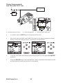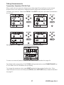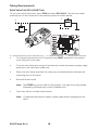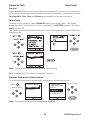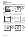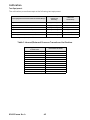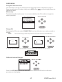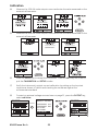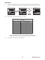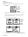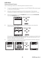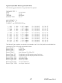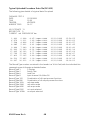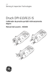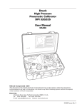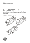
1
GE
Measurement & Control
Druck DPI 610/615 IS
Intrinsically Safe Portable Pressure Calibrator
User manual - K0430
English
To select the manual in an available language go to:
//www.ge-mcs.com/toolsupport/manuals.htm
Français
Pour choisir le manuel dans une langue disponible, accédez à :
//www.ge-mcs.com/toolsupport/manuals.htm
Deutsch
Um das Handbuch in einer vorhandenen Sprache auszuwählen, gehen Sie zu:
//www.ge-mcs.com/toolsupport/manuals.htm
Italiano
Per scaricare il manuale in una delle lingue disponibili consultare la pagina:
//www.ge-mcs.com/toolsupport/manuals.htm
Español
Para seleccionar el manual en uno de los idiomas disponibles vaya a:
//www.ge-mcs.com/toolsupport/manuals.htm
Português
Para selecionar o manual em uma língua disponível vá para:
//www.ge-mcs.com/toolsupport/manuals.htm
WARNING
Before operating this intrinsically safe instrument, read the safety instructions and
the special conditions stated on the ATEX certificate (Appendix 2)
Safety
The manufacturer has designed this equipment to be safe when operated using the
procedures detailed in this manual. Do not use this equipment for any other purpose
than that stated.
This publication contains operating and safety instructions that must be followed to
ensure safe operation and to maintain the equipment in a safe condition. The safety
instructions are either warnings or cautions issued to protect the user and the equipment
from injury or damage.
Use suitably qualified * technicians and good engineering practice for all procedures in
this publication.
Pressure
Do not apply pressures greater than the safe working pressure to this equipment.
Maintenance
The equipment must be maintained using the procedures in this publication. Further
manufacturer’s procedures should be carried out by authorized service agents or the
manufacturer’s service departments.
www.ge-mc.com
For technical advice contact the manufacturer.
*
A qualified technician must have the necessary technical knowledge,
documentation, special test equipment and tools to carry out the required work on
this equipment.
Symbols
This equipment meets the requirements of all relevant European safety
directives. The equipment carries the CE mark.
This symbol, on the instrument, indicates that the user should refer to
the user manual. This symbol, in this manual, indicates a hazardous
operation.
This symbol, on the instrument, indicates do not throw-away in
domestic bin, hazardous material, dispose correctly in accordance with
local regulations.
i
K0430 Issue No. 4
K0430 Issue No. 3
ii
ATEX Approved Models
Introduction
These instructions detail the requirements for using the DPI 610 IS and DPI 615 IS
intrinsically safe pressure calibrator in a hazardous area. Read the whole publication
before starting.
Markings
II 1 G.................................................................... Equipment group & category
Ex ia IIC T4 Ga.................................................................. Hazardous location markings
BAS02ATEX1174X ................................................................................ Certificate number
1180.................................................................................................................................. CE Mark
DPI 61X IS ...................................................................................... Specific apparatus type
(Pressure Range in mbar or psi ........................................ Full-scale pressure rating
Druck LTD. Groby LE6 OFH, UK .................... Manufacturer's name and address
SN *******/YY-MM.................................. Serial number and date of manufacture,
Year-Month.
Requirements and Conditions
Batteries
WARNING: Only replace batteries in a safe area.
•
Power supply use only 6 x LR14 (C): Duracell MN1400-LR14, Procell lndustrial
MN1400-LR14, Energizer E93.KR14.C.AM2, Energizer Industrial EN93 or Varta
4014 LR14.C.AM2.
Special Conditions for Safe Use
1. The DPI 61X IS Series Pressure Calibrator is not capable of withstanding the 500V
r.m.s. electric field strength test between the external connectors and frame of the
apparatus as required by Clause 6.4.12 of EN 50020 and this must be taken into
account when using the apparatus for input measurements in a system.
2. The outer enclosure may contain light metals in the form of aluminium, magnesium,
titanium or zirconium. Therefore, the apparatus must be installed in such a manner
as to prevent the possibility of it being subject to impacts or friction. An optional
carrying case is case is available for transporting the pressure calibrator to and from
the location of use. When the carrying case is used, special condition for safe use
item #2 does not apply.
iii
K0430 Issue No. 4
Electrical Parameters
Maximum Output Parameters at the External Measurement Connectors:
lin (SK1)
Vin (SK2)
SwitchIn (SK3)
Uo= 1.1V d.c.
Io = 0.16 mA d.c.
Po= 0.15 mW
Ci = 0.05 µF
Li = 0
Uo= 1.1V d.c.
Io = 0.11 µA d.c.
Po= 0.03 µW
Ci = 0
Li = 0
Uo= 1.1V d.c.
Io = 12 mA d.c.
Po= 11 mW
Ci = 0.05 µF
Li = 0
lout (SK6)
RS232
External Transducer
Uo= 7.9V d.c.
Ci = 0
Li = 0.1 mH
Uo= 7.6V d.c.
Io = 82 mA d.c.
Po= 162 mW
Ci = 0
Li = 0
Um = 250V
Uo= 7.6V d.c.
Io = 155 mA d.c.
Po= 0.43 W
Ci = 0.15 µF
Li = 0.9 mH
Co = 8.6 µF
Lo = 0.3 mH
The output parameters at sockets SK1, SK2 and SK3 do not exceed the values specified
in Clause 5.4, Simple Apparatus, of EN 50020.
Maximum Safe Input Parameters:
Sockets SK1, SK2, SK3 and SK6
Ui= 30V
li= 100 mA
Pi = 1.0W
Installation
WARNING: Do not use tools on the pressure calibrator that might cause
incendive sparks - this can cause an explosion.
•
•
Provide additional protection for equipment that may be damaged in service.
Installation should be carried out by qualified plant installation technicians in
compliance with the latest issue of EN 60079-14.
Declaration Requirements
The DPI 610 IS and DPI 615 IS pressure calibrators are designed and manufactured to
meet the essential health and safety requirements not covered by the EC Type
Examination Certificate BAS02ATEX1174X when installed as detailed above. The
intrinsically safe pressure calibrators are designed and manufactured to protect against
other hazards as defined in paragraph 1.2.7 of Annex 11 of the ATEX Directive 94/9/EC.
K0430 Issue No. 3
iv
Specification
Safe working pressure
20 bar range (300 psi)
1.75 x full-scale
350 bar range (5000 psi)
1.2 x full-scale
400 bar range (6000 psi)
1.5 x full-scale
All other ranges
2 x full-scale
Accuracy
Combined non-linearity, hysteresis and repeatability
±70 mbar range (2 inHg)
0.05% F.S.
up to ±150 mbar (4.4 inHg)
0.05% span
200 mbar to 20 bar (3 psi to 300 psi) [Calibrator]):
0.025% F.S.
35 bar to 700 bar (500 psi to 10000 psi) [Indicator]
0.025% F.S.
70 bar to 400 bar (1000 psi to 6000 psi) [Hydraulic]
0.025% F.S.
Pressure Ranges
Refer to the pressure range matrix in the data sheet.
Temperature Effects
±0.004% of reading/°C (averaged over -10° to +40°C w.r.t. 20°C)
±0.002% of reading/°F (averaged over +14° to 104°F w.r.t. 68°F)
Power supply
Batteries
6 x 1.5 V C cells, alkaline (up to 60 hours nominal use at 20°C)
Voltage Inputs
Range:
±30V
Accuracy
±0.05% rdg, ±0.004% F.S.
Resolution
100µV max
Current Inputs
Range:
±55mA
Accuracy
±0.05% rdg, ±0.004% F.S.
Resolution
1µA max
Current sink
Range:
24mA
Accuracy
±0.05% rdg, ±0.01% F.S.
Resolution
1µA max
Display
Size:
60 x 60 mm (2.36” x 2.36”) LCD Graphics
Reading
±99999, update rate 2 readings/sec
Environment
Operating Temperature:
-10°C to 50°C (+14°F to 122°F)
Calibrated Temperature:
-10°C to 40°C (+14°F to 104°F)
Storage Temperature:
-20°C to 60°C (-4°F to 140°F)
Calibration Temperature:
21°C ±2°C (70°F ±4°F)
Sealing
Sealed to IP54 (NEMA 4)
Physical
Size:
300 x 170 x 140 mm (11.8” x 6.7” x 5.5”)
Weight:
3 kg (6.6lb)
v
K0430 Issue No. 4
Introduction
General
Description of Procedures
Summary of Functions
Using this Guide
OPERATOR CONTROLS
DISPLAY
HARD KEY FUNCTIONS
SOFT KEYS
CURSOR KEYS
ELECTRICAL CONNECTIONS
Getting Started
Fitting Batteries
Switching On
Change Pressure Units
Voltage and Current Measurement
Typical Calibration Set-up (Pressure to Voltage)
Zero Display Reading
1
2
3
3
4
5
5
6
7
7
8
8
9
9
Task Selection
Task Key
Using Task Functions
Set Units
Cal Mode (DPI 615 instruments only)
Basic Mode (Task BASIC)
10
10
10
11
11
Taking Measurements
Pressure Transmitter (P-I) Task
Voltage Output Pressure Transmitter (P-V) Task
Pressure Converter (P-P) Task
Current to Pressure Converter (I-P) Task
Pressure Switch Test (P-Switch) Task
Pressure to Display (P-Display) Task
Leak Test (Leak Test) Task
Transmitter Simulator (TX SIM) Task
Relief Valve Test (REL VALVE) Task
12
12
13
14
14
15
16
17
18
K0430 Issue No. 3
vi
Advanced Task
General
Select Input
Ambient Temperature Measurement
Process Functions
Tare Process Function
Min/Max Process Function
Filter Process Function
Flow Function
% Span
Select Output
Electrical Outputs (Loop Power)
mA Step
mA Ramp
mA Value
Define New Task
Clear Task
19
19
19
20
21
22
22
23
23
24
24
25
26
27
28
28
Memory Operations
Saving Display or Data Log
Store Operations (Screen Snapshots)
Recalling Stored Data (Screen Snapshots)
Datalog Operations
Auto Log (Timer)
Manual Logging
Recall Data Log Files
Uploading Data Log Files
Delete Data Log and Procedure Files
Downloading Procedure Files (DPI 615 instruments only)
Running Procedure Files (DPI 615 instruments only)
Recalling Data Files (DPI 615 instruments only)
Using Set-up
General
Store Mode
Contrast
Settings - Select Set-up Option
Units
Define Special Units
Language
RS232
Powerdown
Calibration
vii
29
29
29
30
30
30
31
32
32
33
34
35
36
36
36
37
37
37
38
38
39
39
K0430 Issue No. 4
Date and Time (Real Time Clock)
Date Format
Set Date
Set Time
Calibration
General
Calibration Check
Calibration Adjustment
Guide to Calibration Procedures
Test Equipment
Using the Calibration Menu
Change PIN
Calibrate Internal Ranges
Internal Pressure Range
Voltage Input Range (5 Volts)
Voltage Input Range (30 Volts)
Current Input Range (55 mA)
Current Output Range (24 mA)
Ambient Temperature Channel
Calibrate External Sensors
Add External Sensor
Hydraulic Calibrator Versions
Introduction
Safety Instructions
Preparation for Use
Bleeding the System
Operation
Draining the Hydraulic Fluid
Flushing, Replenishing or Changing the Hydraulic Fluid
Appendix 1 - Datalog File Example
Typical Uploaded Datalog File (DPI 610)
Typical Uploaded Procedure Data File (DPI 615)
Appendix 2 - ATEX Certificate of Conformity
K0430 Issue No. 3
viii
40
40
40
40
41
41
41
41
42
43
43
43
44
45
47
49
51
54
55
56
59
60
60
61
62
62
63
67
68
INTRODUCTION
Summary of Functions
General
The DPI 610 IS and DPI 615 IS intrinsically safe instruments measure and display
pneumatic and hydraulic pressure applied to the test port. Pressure measurement can
be absolute, gauge and sealed gauge and in ranges from 2.5 mbar to 700 bar (1.0 inH2O
to 10000 psi).
Calibrator versions of this instrument contain pneumatic or hydraulic pressure
generation components to produce pneumatic pressure ranges between -1 to 20 bar (14.5 psi to 300 psi) and hydraulic pressure ranges up to 400 bar (6000 psi)
Using external electrical connections, the DPI 610 IS and DPI 615 IS intrinsically safe
instruments measure ±30 volts d.c. and ±55 mA. An integral sensor provides
measurement of ambient temperature. Additional sensors (option B1) connect to an
external connector and extend the pressure measurement range and include differential
pressure measurement. The DPI 615 instrument has an RS232 connector to enable
downloading of test data to a compatible documenting system. Six alkaline C size
batteries, IEC Type LR14, power the instrument.
Important Notice
Zinc-carbon and zinc-chloride cells must NOT be used in this instrument.
Use only the battery types as shown in the table on page 7.
Description of Procedures
The procedures apply to both the DPI 610 IS and the DPI 615 IS instruments unless
otherwise stated. In the procedures in this manual, hard (fixed function) and soft
(variable function) key operations are shown in bold type : TASK and F1. These
statements mean press the TASK key and press the F1 key. Soft key operations can be
assigned to both the F1 and F2 keys. Where a specific soft function is referred to it is
written in bold italics (e.g.) PROCESS.
This instrument has a number of operating modes that are described in simplified form in
the following sections. Diagrams accompanying the procedures give typical selection
sequences and shaded controls indicate that this control key should be pressed in the
appropriate sequence. Diagrams should be read from left to right, top to bottom where
appropriate. A shaded display soft box indicates that the function key immediately
below that soft box should be pressed (either F1 for the left hand soft box or F2 for the
right).
In the above diagram the following key sequence is indicated.
(a)
Press the F2 key (the key immediately below the UNITS soft box).
(b)
Use the Up and Down cursor keys (only) to select the required option. (If all keys
shaded, use all these keys to select or enter data).
(c)
Press the ENTER key.
1
K0430 Issue No. 4
INTRODUCTION
Summary of Functions
Using This Guide
The following key symbols are used in the procedure diagrams:
Shaded cursor keys indicate that a combination of these four keys, Up,
Down, Left and Right should be used to (e.g.) enter an alpha numeric
value or to select a function.
Indicates the ENTER key. Used to confirm an operation or a selection.
Shading indicates key operation.
Exit key, used to clear current menu selection and return to next menu
level above current level. Used as an escape key from current operation.
Shading indicates key operation.
Hardkey (total 7). Legend beside key symbol indicates function. Shading
indicates key operation.
Maximum Instrument Ratings
The following table shows the maximum measurement input ratings of the instrument
which should not be exceeded.
PRESSURE
120% FULL SCALE
VOLTAGE
30 V d.c.
CURRENT
55 mA d.c.
Note 1: The display flashes if the input pressure, voltage or current overrange.
Note 2: Max applied voltage for external loop supply = 30V dc (see page 8).
K0430 Issue No. 4
2
INTRODUCTION
Summary of Functions
OPERATOR CONTROLS (Figure 1 and 2)
These divide into two groups, the operator/display controls (Figure 1) and the pressure/
vacuum generation components (Figure 2). The operator controls and a typical display,
common to all instrument versions, is shown below.
1
max 30V
DPI 615 IS
TASK: BASIC
2
V
VOLTAGE
bar
PRESSURE INT
CURRENT
PRESSURE
UNITS
F1
F2
3
4
6
7
1
4
Display
Enter Key
2
5
5
Electrical Measurement Input Sockets
Function (soft) Keys
6 Hard Keys
Figure 1 - DPI 610/615 IS Key-pad
3
7
Cursor Keys
On/Off Key
DISPLAY
The display and key-pad of the instrument divides into four distinct sections. The two
main sections of the display are used to show an input and an output. The remaining
two sections show the status display area and define the soft key functions. A typical
display is shown below:
Status display
TASK: BASIC
-
+
Input display
VOLTAGE
V
Output display
PRESSURE INT
Soft boxes
CURRENT
3
bar
PRESSURE
UNITS
K0430 Issue No. 4
INTRODUCTION
Summary of Functions
HARD KEY FUNCTIONS (Fig. 1)
Key
I/O
SETUP*
ZERO
INPUT*
TASK
Function
Page
reference
This key selects the instrument ON and OFF.
7
The SETUP key provides access to the instrument’s general
configuration parameters that are set-up to certain default
parameters on delivery.
36
The ZERO key zeroes either the selected input or output display, only if
the display reading is within 5% of zero. Attempts to zero a larger
offset result in an error message, Zero too large.
9
The INPUT key selects the input parameter to be displayed.
The TASK key rapidly configures the instrument for a number of
different types of external device calibration. There are twenty task
configurations available, eleven pre-programmed configurations and
nine user defined configurations
18, 19
10
The OUTPUT key selects the output parameter to be displayed.
24-27
Depending upon how the instrument’s STORE mode is set-up, this key
is used either to store up to 20 display screens (in SNAPSHOT mode),
or to manually log a screen in DATALOG mode.
29, 36
STORE*
28, 31, 35
RECALL*
This key recalls a previously stored screen to the display. Depending
on the STORE mode set-up, operation of this key recalls either the
snapshot of a previously stored screen or data log file. In STORE
mode, selection displays the last screen stored. By using the cursor
keys, the operator can scroll either forward or back through memory
locations.
OUTPUT*
ENTER
EXIT
The ENTER key either enters data (accept entered data), or, in
conjunction with the soft keys, accepts a given selection.
2
The EXIT key operates in conjunction with all the other hard and soft
keys to exit from the current screen or menu level, to the level
immediately preceding it. To quit completely from any menu level,
press EXIT until the MEASURE/SOURCE screen is displayed.
2
* These key functions are not available in BASIC mode
K0430 Issue No. 4
4
INTRODUCTION
Summary of Functions
SOFT KEYS (Fig. 1)
Three soft keys, designated F1, EXIT and F2, are situated immediately below the display
as shown below. These keys have their function allocated by the instrument software
which is indicated in the bottom of the display (Voltage for F1 and Units for F2 in this
example). They are used to select menu (program) options and are fully described under
the appropriate section headings.
CURSOR KEYS (Fig. 1)
The cursor keys consist of a block of four keys, designated up , down , left , and
right . In programs where options need to be selected from a list, (e.g.) the TASK
selection program, the up and down cursor keys are used to highlight one of the
options, from which it can be selected by the ENTER key. In TASK mode, where more
than one page of options are provided, the left , and right cursor keys will switch
between pages.
3
2
4
1
5
11
6
7
8
9
10
1
3
5
7
9
11
Test port, connect to unit under test
Cover (external interfaces)
Cursor keys
Release valve (releases pressure through 8)
Select positive or negative pressure
Fine pressure adjuster
2
4
6
8
10
Hard keys
Electrical inputs
Function (soft) keys
Vent port
Pump
Figure 2 - DPI 610/615 IS Calibrator Controls
5
K0430 Issue No. 4
INTRODUCTION
Summary of Functions
ELECTRICAL CONNECTIONS
1
2
1
Cover, closed when
not using connectors
2
External transducer
3
RS232 connector
4
Temperature sensor
U SE
IN SAR S2 32
AR EA FE
O N LY
3
4
Figure 3 - Electrical System Connections
Measurement inputs and Source outputs are made via the control panel sockets as
shown below:
2
1
max 30V
CAT II
DPI 615 IS
TASK: BASIC
3
INPUTS
V
VOLTAGE
OUTPUTS
bar
PRESSURE INT
CURRENT
PRESSURE
UNITS
F1
1
4
Status window 2
Output window
Input window
4
F2
3
Electrical measurement input sockets
Figure 4 - Electrical Measurement Inputs/Source Outputs
K0430 Issue No. 4
6
Getting Started
Fitting Batteries
1
Manufacturer
Type No.
Energizer
Industrial Type EN93
Energizer
Type E93.LR14.C.AM2
Duracell
Type MN1400-LR14
Varta
No.4014 Type LR14.C.AM2
Procell
Industrial Type MN1400-LR14
3
TASK: BASIC
-
+
VOLTAGE
V
PRESSURE INT
bar
CURRENT
2
1
Cover fixing
screws.
2
Six alkaline C
cells, see table.
Only use the
battery type in
the table.
3
Low battery
indication.
PRESSURE
UNITS
WARNING:
BATTERIES MUST ONLY BE FITTED IN A SAFE AREA.
USE ONLY THE BATTERIES SPECIFIED IN THE TABLE.
Caution:
Old batteries can leak and cause corrosion. Never leave discharged batteries in
the instrument. Old batteries should be treated as hazardous waste and
disposed of accordingly.
Switching On
Press the I/O switch on the front panel and proceed as follows:
The first time that the instrument is powered up, it will power-up in BASIC mode with the
main screen displaying voltage in the input display area and pressure in the source
display area. To switch to Current as input, press F1 as shown. Similarly, F1 to return to
Voltage.
Note: No other keys are active in this mode and the instrument can only be reconfigured
by pressing the TASK key and selecting another mode.
7
K0430 Issue No. 4
Getting Started
Change Pressure Units
To change the pressure units proceed as follows. If the four units displayed are not the
units required, press TASK and select any task, other than BASIC, press SETUP and
proceed as detailed on page 36. To return to BASIC mode, press TASK and select BASIC.
In BASIC mode, the unit is configured to carry out basic Pressure to Voltage (P to V) or
Pressure to Current (P to I) tests, a typical test procedure follows:
Voltage and Current Measurements
Connect the electrical input sockets as follows for voltage and current measurements.
Use the test leads provided and DO NOT push bare wires into the sockets.
max 30V
max 30V
-
+
V
Vin
Vin
-
mA in
55mA
max
mA in
55mA
max
+
mA Sink
mA Sink
Voltage
Current
Maximum applied voltage = 30V dc.
Maximum input current = 55mA dc (at 30 V dc)
K0430 Issue No. 4
8
Getting Started
Typical Calibration Set-up (Pressure to Voltage)
Connect a device under test to the instrument as shown below:
D
C
F
+
A
P
3
+
B
CD
E
V
-
-
Max 30V
CAT II
DPI 615 IS
+
D
TASK: BASIC
V
VOLTAGE
bar
PRESSURE INT
PRESSURE
UNITS
CURRENT
F1
EXIT
F2
A - External pressure source (indicator instruments only) B - Pressure regulator
C - Pressure/voltage device D - Barrier E - Excitation 10V F - Safe area
•
General Procedure
Use the hand-pump to pressurize the system to the required level as indicated on
the display. Allow the display to settle and screw the volume adjuster in or out as
a fine adjustment to the required pressure. Record the input: Voltage, reading at
each applied pressure.
Zero Display Reading
Both the input and output readings can be set to zero by using the ZERO key and if the
displayed reading is within 5% of zero. To zero either the INPUT or OUTPUT displays,
proceed as follows:
9
K0430 Issue No. 4
Task Selection
Task Key
The TASK key is used to set-up the instrument for a number of specific types of test.
There are two modes BASIC and ADVANCED and nine other specific types of test which
automatically configure the instrument on selection from the TASK menu. The tasks
available under the TASK menu are held on three pages shown below. To select a task
from the menu, press the TASK key, position the cursor over the required task and press
the ENTER key as shown below. Use the right/left cursor keys to switch between pages.
Using TASK Functions
Specific tasks are selected as shown above. The following diagrams show how to
connect the unit under test (UUT) for each task selectable under the TASK menu.
Input and output units, where applicable, can be selected by pressing either the INPUT or
OUTPUT keys as shown below.
Set Units
Note: If the four units displayed are not the units required, press SETUP, select SETTINGS
and refer to select regular units on page 37.
K0430 Issue No. 4
10
Task Selection
Cal Mode (DPI 615 versions only)
Cal mode, which is available in tasks P-I, P-P, P-V, P-P, P-DISPLAY and P-SWITCH, provides
a method of setting up test parameters manually. Downloaded test procedures can also
automatically set up and turn on the Cal Mode function. The method of turning on and
setting up Cal Mode is shown below for a P-I task. A similar method can be used for all
the other tasks applicable to the Cal Mode function.
..........
TASK : P-I
DATALOG
..........
24V OFF
psi
mA
P
I
mA
0.00
=
4.00
2000.00
=
20.00
OUTPUT
=
LINEAR
MAX. ERROR =
0.05%
ERROR TYPE =
% span
psi
TURN ON
CAL MODE
SELECT VALUE
TASK : P-I
DATALOG
24V OFF
mA
.
%span FAIL
psi
TURN OFF
CAL MODE
CHANGE
VALUE
Pressing the F1 key (TURN ON CAL MODE), provides the set-up screen for the CAL mode.
Initially, the cursor is placed in the UUT SPAN field to allow the required span range to be
entered. The corresponding values for the UUT output parameter (current) are then set,
followed by the maximum error value and error type (%rdg or % span). When all test
parameters have been set-up, the screen changes to display the input and output and
the test results. The test result can only be displayed to within a range of ±9.99%. If the
test result is outside this range, either the left pointing (-ve error) or right pointing (+ve
error) chevrons are displayed. Within this error band, the actual tolerance value is
displayed. Test results can either be stored as snapshots or logged as data log files,
depending on how the instrument has been set-up.
Basic Mode (Task BASIC)
This instrument will power-up in this mode the first time that it is used. To select BASIC
from any other task, press the TASK key and select BASIC and press the ENTER key.
BASIC mode is fully described in the Getting Started, section (see page 7).
11
K0430 Issue No. 4
Taking Measurements
Pressure Transmitter (P-I) Task
Select the P-I task from the task menu and connect the Unit Under Test (UUT) to the
calibrator as shown below:
D
C
P
A
I
F
+
+
-
E
-
3
Max 30V
CAT II
DPI 615 IS
B
D
TASK : P-I
SNAPSHOT MODE
CURRENT
mA
PRESSURE INT
bar
F1
EXIT
F2
A - External pressure source (indicator instruments only) B - Pressure regulator
C - Pressure to current device D - Barrier E - External supply F - Safe Area
•
•
If required, select the output units as described on page 10.
If applicable, turn on Cal Mode and set-up test parameters as detailed on page 11.
Voltage Output Pressure Transmitter (P-V) Task
Select the P-V task from the task menu and connect the Unit Under Test (UUT) to the
instrument as shown below:
D
C
F
+
A
P
3
+
B
CD
E
V
-
-
Max 30V
CAT II
DPI 615 IS
+
D
TASK: BASIC
V
VOLTAGE
bar
PRESSURE INT
PRESSURE
UNITS
CURRENT
F1
EXIT
F2
A - External pressure source (indicator instruments only) B - Pressure regulator
C - Pressure to voltage device D - Barrier E - External supply F - Safe Area
•
•
If required, select the output units as described on page 10.
If applicable, turn on Cal Mode and set-up test parameters as detailed on page 11.
K0430 Issue No. 4
12
Taking Measurements
Pressure Converter (Pressure to Pressure) Task
Select the P-P task from the task menu and connect the Unit Under Test (UUT) to the
calibrator as shown below. Testing a converter requires one pressure to be applied to
the unit under test (UUT) and another (converter output) to be measured. The additional
measurement is provided by the external transducer option.
Method
•
Connect the UUT to the instrument as shown below. Plug the external transducer
into the instrument as shown below:
C
A
D
3
B
E
USE RS2
IN SAF 32
ARE A E
ONLY
A - External pressure source (indicator instruments only)
B - Pressure regulator
C - External pressure source
D - Pressure to pressure device E - External transducer
•
Press the TASK key and select the P-P task. Providing the external transducer has
been calibrated and its parameters stored in the instrument, the display will
show External pressure in the input window and calibrator Output pressure in
the output window. If an error message “NO SENSOR OR CAL INVALID” is
displayed, this indicates that the external transducer has not been entered and/
or calibrated with the instrument. Refer to page 56 for details of adding an
external transducer. If an external transducer change is made, switch the
calibrator off and then on to load new transducer data.
•
If required, select the input and output units as described on page 10.
•
If applicable, turn on Cal Mode and set-up test parameters as detailed on page
11.
13
K0430 Issue No. 4
Taking Measurements
Current to Pressure Converter (I-P) Task
C
A
D
-
P
B
3
CD
I
+
+
C
Max 30V
CAT II
DPI 615 IS
E
TASK : I-P
SNAPSHOT MODE
bar
PRESSURE INT
OUTPUT
NEW VALUE
CURRENT
F1
A - External pressure source
D - Safe area
•
OK
EXIT
mA
F2
B - Pressure to current device (24V)
E - External supply
C - Barrier
Use the up and down cursor keys to adjust the loop current to the required
value. Alternatively, press ENTER and use cursor keys to enter a finite value.
Cursor keys can then be used to nudge the output either up or down.
If required, change pressure units with INPUT key. A flashing CHECK LOOP
message indicates either an open circuit supply loop (or no external supply).
Pressure Switch Test (P-SWITCH) Task
C
A
3
B
max 30V
DPI 615 IS
TASK : P-SWITCH
SNAPSHOT MODE
CONTACT STATE
bar
PRESSURE INT
RUN
F1
A - External pressure source
•
•
•
•
B - Pressure regulator
F2
C - Pressure switch under test
Contact state will be shown on display. When contacts close, buzzer sounds.
To run switch test, close vent valve and press the RUN (F1) key.
Using the hand-pump, increase the applied pressure to just below the switch
operating point. Screw the volume adjuster in until the switch operates (the
operating pressure of the switch is then written to the display).
Reduce pressure until the switch releases (indicated by the switch symbol). The
release pressure is then written to the display and the hysteresis displayed.
K0430 Issue No. 4
14
Taking Measurements
Pressure to Display (P-DISPLAY) Task
P-Display is a special application of Data Log. To use this mode, select Data Log from the
Store Mode menu as detailed on page 36. Connect the UUT to the instrument as shown
below and, if required, turn on and set-up Cal Mode (see page 11).
A
C
B
max 30V
DPI 615 IS
TASK : P-DISPLAY
SNAPSHOT MODE
DISPLAY
bar
PRESSURE INT
CHANGE
VALUE
F1
A - External pressure source
B - Pressure regulator
F2
C - Dial gauge under test
•
Press TASK and select P-DISPLAY. If required, use OUTPUT key to change
pressure units.
•
Set-up a data log file as detailed on page 30.
Note: TRIGGER field, automatically set to KEYPRESS, cannot be changed.
•
Apply a series of test pressures to the device under test. Enter displayed
reading at each pressure and log each point:
•
After logging final test point, terminate as follows:
15
K0430 Issue No. 4
Taking Measurements
Leak Test (LEAK TEST) Task
A
C
B
max 30V
DPI 615 IS
TASK : LEAK TEST
SNAPSHOT MODE
bar
PRESSURE INT
WAIT
DURATION
60
60
secs
secs
bar
bar
START PRESS
STOP PRESS
PRESS CHANGE
LEAK RATE
CHANGE
VALUE
F1
A - External pressure source
B - Pressure regulator
bar
bar/m
RUN
F2
C - Device/system under test
•
If required, use the INPUT key to change pressure units.
•
Set-up the leak test WAIT and DURATION times to the required values as shown
below. A minimum wait period of 3 minutes is recommended.
•
Close the vent valve and pressurize the device/system to the required LEAK TEST
pressure.
•
Press the RUN (F2) key to start the leak test. When completed, the beeper sounds
and the leak test results are written to the display.
K0430 Issue No. 4
16
Taking Measurements
Transmitter Simulator (TX SIM) Task
When used with an external voltage source (see page 24), provides a current output
proportional to the calibrator’s measured output pressure (indicated pressure on
indicator only version). Select task TX SIM. Press EXIT to skip set-up screen if parameters
are correct.
On completion of Tx SIM set-up, the display is configured as follows :.
Connect an external power source to the output loop as detailed on page 24.
To subsequently change any of the Tx SIM scaling parameters, press CHANGE VALUE key
(F1) to obtain the TX Simulation set-up display.
To change the pressure units, press INPUT and select the required scale units. If the
required scale units are not listed, press SETUP, select SETTINGS and proceed as detailed
on page 37.
17
K0430 Issue No. 4
Taking Measurements
Relief Valve Test (REL VALVE) Task
To carry out a relief valve test, press TASK and select REL VALVE. Connect the output
pressure port of the instrument to an external system as shown below:
C
A
3
B
max 30V
DPI 615 IS
TASK : RELVALVE
SNAPSHOT MODE
MAXIMUM
MINIMUM
bar
PRESSURE INT
bar
PRESSURE INT
RESET
MAX/MIN
F1
A - External pressure source (indicator only)
B - Pressure regulator
F2
C - Relief valve under test
•
To change the pressure units, if required, press INPUT and select the required
units using the cursor keys.
•
Close the vent valve and, using the hand-pump or external pressure supply, apply
pressure to the relief valve under test.
•
When the relief valve operates, the maximum recorded pressure indicates the
operating point of the valve.
•
Record the test results.
Note: The STORE key can be used for this purpose. Use right cursor key initially,
followed by up/down keys to enter Snapshot text.
•
Open vent valve to release test pressure.
Note: If using external pressure supply, isolate supply before opening the vent
valve.
K0430 Issue No. 4
18
Advanced Task
Select Input
General
Advanced task allows the user to configure the instrument to monitor one of a number of
different input measurements and outputs (sources). Additionally, five process functions,
Tare, Max/Min, Filter, Flow and % Span can be applied to the input functions.
Select Input
To select an input channel, select ADVANCED task from the task menu. The display
shows the list of the input selections and, if available, the PROCESS soft box (F1) and the
UNITS soft box (F2).
The following procedure shows the method of input channel selection and the method of
changing units:
Note: Left/right arrow keys function as page up/down keys.
Refer to pages 20 to 23 for details of process functions.
Ambient Temperature Measurement
To set-up the instrument to read ambient temperature, proceed as follows:
INPUT
SELECT INPUT
SELECT AIR
TEMPERATURE
UNITS
SELECT INPUT
AMBIENT TEMP
NO INPUT
SELECT UNITS
CELSIUS
FAHRENHEIT
PROCESS
UNITS
Note: Ensure that the temperature reading has stabilised.
19
K0430 Issue No. 4
Advanced Task
Process Functions
Process Functions
If required, the following process functions are available on the input display but only in
ADVANCED task. If the instrument is in any other mode i.e. BASIC or any other task
mode, the input and output displays must first be configured in ADVANCED task.
Note: PROCESS functions are not available to the output channel.
A summary of the process functions follows.
•
Tare
Allows either the current display value or a manually
entered value to be tared off display parameter reading.
•
Max/Min
Displays running Max/Min and present display values
simultaneously. Resettable via F1 key.
•
Filter
Applies low pass filter function to displayed parameter.
Filter characteristics (Settling time and Band) are user
programmable.
•
Flow
Applies square root function to displayed parameter.
•
% Span
Converts displayed parameter reading to a percentage of
span. Span definable via the F1 key.
Following selection of ADVANCED from the task menu, press the INPUT key. Use the up
or down cursor keys to select the required input. Press the PROCESS (F1) key and
use the left or right cursor keys to enable the process on/off:
Press ENTER to switch the process ON with existing settings or F1 to change process
settings (where applicable).
K0430 Issue No. 4
20
Advanced Task
•
Process Functions
Tare Process Function
To set-up a Tare function, enable TARE from the process menu and press F1 to
enter the Tare SETTINGS functions.
Disable TARE by entering process menu and turning the function OFF.
Note: Last TARE setting is retained and will be applied when function is next
enabled.
Tare Current input Reading To tare-off the current display reading, proceed as
follows:
Tare Off An Entered Value To tare-off an entered value current, proceed as
follows:
Note: Display shows the last entered Tare Value.
21
K0430 Issue No. 4
Advanced Task
•
Process Functions
Min/Max Process Function
To set-up an input display to show min/max and present input reading, enable
MIN/MAX from the process menu and press F1 (SETTINGS) to provide RESET
function. The display now shows the max/min values as follows:
Reset Max/Min display at any time by pressing the
F1 key.
To quit max/min, press INPUT, select MAX/MIN
from process menu and switch the function off.
•
Filter Process Function
To apply the low pass filter to a selected input, enable FILTER from the process
menu and press F1 (SETTINGS) to provide access to the filter parameters. Two
settings are required, Time to Settle and Band.
To examine the current filter settings and exit without change, press the EXIT key.
The set-up procedure is as follows:
K0430 Issue No. 4
22
Advanced Task
•
Process Functions
Flow Function
To apply the flow function to a selected input, enable FLOW from the process
menu and press ENTER. The square root symbol is displayed beside the input
value to indicate that the FLOW function is active:
To cancel FLOW, press INPUT and turn function OFF at
the process menu.
•
% Span
To convert a selected input display from a numerical value to a percentage of fullscale reading, enable SPAN from the process menu and press F1 (SETTINGS) to
provide access to the span definition parameters. Two span definitions are
required, Zero and Full Scale.
To leave span at current setting, press EXIT.
To define zero and full-scale settings, proceed as follows.
To cancel % SPAN, press INPUT and turn function OFF at the process menu.
23
K0430 Issue No. 4
Advanced Task
Select Output
Select Output
To display an output channel, select ADVANCED mode from the task menu. The display
shows the list of output selections and, if available, the UNITS soft box (F2).
The following procedure shows the method of output channel selection from two pages
of options. The second page can be obtained directly from the first by pressing the right
cursor key:
Note: Left/right arrow keys function as page up/down keys.
To change the output units (pressure channels only), select the channel with the cursor
keys and press F2 before pressing ENTER.
Electrical Outputs (Loop Power)
All the electrical outputs, the output loop must be powered from an external supply
(current sinking).
External connections to the front panel of the instrument are shown below.
B
max 30V
CAT II
D
Vin
+
55mA
max
mA in
C
-
A
mA Sink
B
Current Sinking
A
Load
B
Barrier
K0430 Issue No. 4
C
(External supply 30 V dc maximum)
24
D
Safe area
Advanced Task
Select Output
mA Step
To select one of the electrical output programs, press the OUTPUT key and proceed as
follows:
On selection of (e.g.) Linear, the output display window changes to show the selected
program of output currents:
•
Connect an external power source as shown on page 24.
•
Press RUN (F1) to run program. A flashing status display CHECK LOOP indicates a
fault in the external loop i.e. supply fault or open circuit.
Note: The dwell time at each step is approximately 10 seconds.
•
Press STOP (F1) when running to stop at any point. Press RUN (F1) to resume.
25
K0430 Issue No. 4
Advanced Task
Select Output
mA Ramp
Press the OUTPUT key and select mA Ramp as shown previously in mA Step.
•
Define ramp required by entering START and END current values as shown below:
•
Connect an external power source as shown on page 24.
•
Press START (F1) to run the program. A status display CHECK LOOP indicates a
fault in the external loop i.e. supply fault or open circuit.
Note: The ramp cycle (min to max or max to min), is approximately 60 seconds.
•
Press STOP (F1) when running to stop at any point. Press CONTINUE (F1) to
resume from point of pause or RESET (F2) to return to start point.
K0430 Issue No. 4
26
Advanced Task
Select Output
mA Value
Press the OUTPUT key and select mA Value from the output menu. The
procedure is shown below:
•
Connect an external power source as shown on page 24.
•
Use up and down cursor keys to adjust output current level. While the loop
is made, a status display indicates OK. A status display CHECK LOOP indicates a
fault in the external loop i.e. supply fault or open circuit.
27
K0430 Issue No. 4
Advanced Task
Task Setup/Removal
Define New Task
To define a new task, proceed as follows.
•
Select ADVANCED from TASK menu.
•
Using the INPUT key, select the required input for the input display and set-up
any process functions required.
•
Using the OUTPUT key, select the required output for the output display.
•
Press TASK and select free. Enter new task name as follows:
On completion of the this procedure, the display reverts to newly set-up task as
shown.
Clear Task
To clear a user defined task, select TASK and proceed as follows:
K0430 Issue No. 4
28
Memory Operations
Store
Saving Display or Data Log
In Store Mode three memory operations can be set-up: None, Snapshot and Datalog.
Refer to Using SETUP for details.
Store Operations (Screen Snapshots)
To store any display (menu displays excepted), press the STORE key. This saves the
current display to the next available location. Supporting text (10 characters) may be
appended. Twenty memory locations are available on a cyclic buffer. When all 20 have
been used, store operations overwrite existing locations, starting at Location 1.
.
Recalling Stored Data (Screen Snapshots)
To recall a previously stored display, press the RECALL key. This recalls the last display
saved. Press the left or right cursor keys to recall the previous or next locations
respectively. To exit RECALL, press the EXIT key.
29
K0430 Issue No. 4
Memory Operations
Datalog
Data Log Operations
Data Log is a special application of store mode which enables the calibrator to either
automatically log displays at preset time intervals or to manually log a display on
operation of the STORE key. Logged data is written to a user specified file.
To set-up a Data Log file, proceed as follows.
•
•
Select a task, other than BASIC. If using ADVANCED, set-up the required output
parameters.
Use SETUP to select Data Log from the Store Mode Menu (See page 36).
Auto Log (Timer)
Press STORE and set-up the Data Log file parameters as shown below. Use CHANGE
VALUE (F1) followed by cursor keys to set field values. For Auto Log, set-up TRIGGER field
to PERIODIC.
Manual Logging
Enter the file details as shown above and select KEYPRESS for TRIGGER field. Screen
reverts to displayed parameters showing set-up file as shown below:
•
Use a combination of STORE and LOG NOW (F1) to log events as follows.
K0430 Issue No. 4
30
Memory Operations
Datalog
Recall Data Log Files
To recall a Data Log file to the display, ensure that DATA LOG is selected from the SETUP
menu and proceed as follows:
Data Log files can be displayed either as text (stored screens) or in graphical form. To
display as text, proceed as follows from the File Summary menu. Select Auto Step to
automatically review each screen at 1 second intervals or use the left and right
cursor keys to manually review.
To display logged data in graphical form, on screen, proceed as follows from the File
Summary menu:
31
K0430 Issue No. 4
Memory Operations
Datalog
Uploading Data Log Files
WARNING
THE RS232 INTERFACE MUST ONLY BE USED IN A SAFE AREA
Connect the RS232 socket of the instrument into either the COM1 or COM2 port of the PC.
Ensure that the RS232 parameters set in the PC match those of the instrument. The
RS232 parameters of the instrument can be checked as detailed on page 38. Set up a
file on the PC to receive the data, (e.g.) in the Windows® Terminal program.
To upload a file, proceed as follows. Appendix 1 gives details of a typical uploaded data
log file.
Delete Datalog and Procedure Files
To delete a Data Log file, or a procedure file (DPI 615 instruments only), proceed as
follows. Alternatively, to delete all logged files simultaneously, select ERASE ALL FILES
(F2) at the erase screen.
K0430 Issue No. 4
32
Memory Operations
Datalog
Downloading Procedure Files (DPI 615 instruments only)
WARNING
THE RS232 INTERFACE MUST ONLY BE USED IN A SAFE AREA
Complete test procedures may be downloaded from a PC to the DPI 615 instrument via
the RS232 port. A procedure consists of a number of Druck Universal Command
Interface (DUCI) commands that are usually assembled by a linking management
software application (e.g.) Druck Intecal.
Before downloading a procedure, the instrument must be in the REMOTE mode. To place
the instrument into REMOTE mode, proceed as follows.
•
Connect the instrument’s RS232 port to a free COM port on a PC.
•
Make sure that the COMMS parameters of the PC match those of the instrument
(refer to page 38).
•
Make sure that the instrument is not already running a procedure. If it is, quit the
procedure.
•
Download the procedure. Procedures are stored in the Data Log directory.
The following sequence shows a typical download sequence that starts with the
instrument in LOCAL mode.
After the procedure file has been downloaded, the instrument is usually returned to the
LOCAL mode by the last command in the procedure file. If the instrument remains in
REMOTE mode, switch it OFF and ON to reset it.
33
K0430 Issue No. 4
Memory Operations
Datalog
Running Procedure Files (DPI 615 instruments only)
To run a procedure, make sure that the instrument is set to Store mode, Data Log (see
page 36), and proceed as follows:
After selecting F1, proceed by entering the User ID and Serial Number and then select F1
(Continue) and follow the on-screen procedural instructions:
When the test procedure for a given UUT has been completed, the result of running the
first test is stored as an AS FOUND file. This file cannot be overwritten. Any subsequent
tests on the device are stored as an AS LEFT file that is overwritten each time the
procedure on this device is run.
When recalling the results of a procedure, the choice of AS FOUND or AS LEFT is provided
(refer to page 35).
K0430 Issue No. 4
34
Memory Operations
Datalog
Recalling Data Files (DPI 615 instruments only)
Data or results files generated by running procedures are stored in the instrument’s data
log directory. To recall a data file to the display, make sure that DATA LOG is selected
from the SETUP menu and proceed as follows:
Use the cursor keys to select either the AS FOUND option or the AS LEFT option for
display. AS FOUND is the result of the first run of a procedure and AS LEFT is the result of
the last time the procedure was run.
Procedure data files can be displayed either as text (stored screens) or in graphical form.
To display as text, select the TEXT option (F1) from the directory and proceed as follows
from the File Summary menu. Select AUTO STEP (F1) to automatically review each
screen at 1 second intervals or use the left or right cursor keys to manually review.
To transmit the selected logged data via the RS232 interface, connect the instrument to a
free COM port on a compatible PC, ensure that the instrument’s RS232 parameters match
those of the PC.
To display logged data in graphical form, on screen, select GRAPH (F2) from the directory
and proceed as follows:
35
K0430 Issue No. 4
Using Setup
General
SETUP mode is available in all modes except BASIC and permits the changing of the
following instrument parameters.
•
Store Mode - None, Snapshot, Data Log.
•
Contrast.
•
Settings - Units, Language, RS232 parameters, Powerdown and Calibration Routines
(Refer to page 41 for calibration details).
•
Date and Time (Real Time Clock).
Store Mode
Select STORE MODE from the Set-up menu and select required mode as follows:
Contrast
Select CONTRAST from the Set-up menu and proceed as follows:
K0430 Issue No. 4
36
Using Setup
Settings - Select Setup Option
To select one of the SETTINGS options from the set-up menu, proceed as follows:
Units
Select UNITS from the SETTINGS menu and proceed as follows:
Define Special Units
Select UNITS from the SETTINGS menu and select SPECIAL UNITS and proceed as
follows:
37
K0430 Issue No. 4
Using Setup
Language
Select the LANGUAGE version required from the SETTINGS menu and proceed as follows:
RS232
Select RS232 from the SETTINGS menu and proceed as follows:
Note: Communications default settings are shown above.
If a communications problem occurs at a particular baud rate, change the baud
rate on the instrument and PC to a lower rate.
K0430 Issue No. 4
38
Using Setup
Powerdown
Select POWERDOWN from the SETTINGS menu and proceed as follows:
If selected to TIMER mode, following a period of inactivity, the instrument automatically
powers off after the preset TIMER period.
If selected OFF, auto power off is inhibited and once switched on, the instrument
remains ON until it is manually switched OFF.
Calibration
Refer to page 41 for a full description of the calibration procedures.
39
K0430 Issue No. 4
Using Setup
Date and Time (Real Time Clock)
Date Format
To set-up the real time clock, select DATE & TIME from the set-up menu and, using the
key, set the required date format:
Set Date
Select DATE from the DATE & TIME menu and, using the cursor keys, change the date as
shown below. The up and down keys change the numerical value of the selected
digit (indicated by the underline cursor) and the left and right keys select the
required digit position.
Set Time
Select TIME from the DATE & TIME menu and, using the cursor keys, change the time as
shown below. The up and down keys change the numerical value of the selected
digit (indicated by the underline cursor) and the left and right keys select the
required digit position.
K0430 Issue No. 4
40
Calibration
General
The instrument is supplied by the manufacturer, complete with calibration certificate(s). A
calibration period of 12 months is recommended. The actual calibration interval
depends on instrument usage and the total measurement uncertainty acceptable for the
specified application.
The DPI 610 IS and DPI 615 IS are very precise measuring instruments and the test
equipment and conditions of test must be suitable for the type of work. A Class A
compensated deadweight tester must be used. The calibration check and calibration
adjustment should be carried out in a controlled environment by a calibration
technician*.
The manufacturer offers a comprehensive and, if required, UKAS accredited calibration
service.
*
A calibration technician must have the necessary technical knowledge,
documentation, special test equipment and tools to carry out the calibration work
on this equipment.
Calibration Check
At the chosen calibration interval, the instrument readings should be compared with a
known pressure standard.
The recommended method starts at 0, increasing in 20% steps to 100% full-scale and
then decreasing in 20% steps to 0.
Note any deviations between the instrument and the pressure standard and consider
traceability (accuracy to a National Standard).
If, after a calibration check, the results exceed the tolerance in the specification (or other
suitable performance standard), carry out a calibration adjustment.
Calibration Adjustment
If the instrument is operating correctly, only zero and full-scale calibration will vary. Any
excessive non-linearity or temperature effects indicate a fault. The instrument should be
returned to a qualified service agent.
Guide to Calibration Procedures
• Use high quality Repeatable and Linear pressure sources and allow adequate
thermal stabilization time before calibration (minimum 1 hour).
•
Conduct the calibration in a temperature controlled and preferably, humidity
controlled environment. Recommended temperature is 21°C, ±2°C (70°F, ±4°F).
•
Use deadweight testers carefully and away from draughts.
•
Review and become familiar with the whole calibration procedure before
commencing the calibration process.
•
The calibration routines cannot be accessed when the instrument is in BASIC mode.
Use the TASK key to select another mode (e.g.) ADVANCED before accessing the
CALIBRATION mode.
41
K0430 Issue No. 4
Calibration
Test Equipment
The calibration procedures require the following test equipment.
Test Equipment and Instrument Parameter/Range
Calibration
Equipment
Accuracy
Calibration
Uncertainty
Digital Voltmeter - 5V input
±30 *ppm ±1 digit
Digital Voltmeter - 30V input
±45 *ppm ±1 digit
±10 *ppm ±5µV
±11 *ppm ± 110 µV
Digital milliammeter - 55mA input
±150 *ppm ±4 digit
±100 *ppm ± 1nA
Digital milliammeter - 24mA output
±150 *ppm ±4 digit
±160 *ppm ± 1nA
Precision thermometer - ambient temperature
±0.2°C
± 0.1°C ±1 digit
Deadweight tester - pressure internal/external
Class A deadweight
<0.025%
*ppm = parts per million
Table 1 Internal/External Pressure Transducer Verification
Nominal applied value as a %
of ±full-scale
Permissible deviation
0% (10% for absolute ranges)
20%
40%
60%
80%
100%
80%
60%
40%
20%
0% (10% for absolute ranges)
± 0.025% FS
± 0.025% FS
± 0.025% FS
± 0.025% FS
± 0.025% FS
± 0.025% FS
± 0.025% FS
± 0.025% FS
± 0.025% FS
± 0.025% FS
± 0.025% FS
K0430 Issue No. 4
42
Calibration
Using the Calibration Menu
The calibration routines are selected from the Settings menu as detailed on page 37.
Enter the calibration PIN code, initially set to 4321, press
and the display shows the
calibration menu.
PIN security
To prevent unauthorised access, it is recommended that the PIN code be changed as
soon as possible.
CALIBRATION
INT RANGES
EXT SENSORS
CHANGE PIN
SELECT OPTION
Change PIN
To change the PIN code, select CHANGE PIN from the calibration menu and proceed as
follows:
Note:
To set and verify a new PIN, the new PIN code must be entered twice.
SET NEW PIN AGAIN
SET NEW PIN
Vvt
Enter New PIN
Enter New PIN
5432
•
If the second code entered differs from the first, the new PIN will not be set.
Calibrate Internal Ranges
Select the INT RANGES from the menu as shown above and follow the calibration
procedure on the display.
43
K0430 Issue No. 4
Calibration
Internal Pressure Range
Use the following procedure for calibrating the internal pressure range.
Note: If calibrating the hydraulic calibrator version, the calibrator must first be primed as
detailed on pages 57 to 64.
(1)
Connect the outlet port of the instrument to a pressure standard.
(2)
Allow the instrument’s temperature to stabilize for a minimum of 1 hour.
(3)
Switch the instrument on, enter CALIBRATION mode and select INT RANGES from
the CALIBRATION menu and then PRESSURE INT.
VOLTAGE IN
(4)
Apply zero pressure and store the zero point:
(5)
Close the vent valve, apply full-scale pressure and store the full-scale point:
(6)
Press the ENTER key to accept the calibration. Press the EXIT key four times to
quit CALIBRATION and SETUP modes.
(7)
Check calibration by applying test pressures in Table 1, page 42.
K0430 Issue No. 4
44
Calibration
Voltage Input Range (5 Volts)
Use the following procedure for calibrating the internal 5 Volt range.
(1)
Switch the instrument on, enter CALIBRATION mode and select INT RANGES from
the CALIBRATION menu shown on page 43.
(2)
Select 5V range for calibration:
CALIBRATION
PRESSURE INT
VOLTAGE IN
CURRENT IN
CURRENT OUT
TEMPERATURE
SELECT CAL OPTION
SELECT RANGE
5 VOLTS
30 VOLTS
SELECT CAL OPTION
(3)
Link the voltage input terminals with a short lead and enter the zero point:
(4)
Remove the shorting link from the voltmeter terminals, connect the Vin terminals
of the instrument to a variable voltage source and connect a digital voltmeter
across the source:
max 30V
+
Cal V
Vin
mA in
-
55mA
max
mA Sink
DVM
45
K0430 Issue No. 4
Calibration
(5)
Set the variable supply voltage to 5V ± 0.1V and enter the measured full-scale
voltage applied:
(6)
Press the ENTER key to accept the calibration. Press the EXIT key once to return
to the calibration menu or four times to quit the CALIBRATION and SETUP modes.
(7)
Verify the instrument calibration by applying the test voltages given in Table 2
(page 48), to the voltmeter (after both voltage ranges have been calibrated).
(8)
Disconnect the calibration/test equipment.
K0430 Issue No. 4
46
Calibration
Voltage Input Range (30 Volts)
Use the following procedure for calibrating the internal 30 Volt range.
(1)
Switch the instrument on, enter CALIBRATION mode and select INT RANGES from
the CALIBRATION menu as shown on page 43.
(2)
Select 30V range for calibration:
CALIBRATION
PRESSURE INT
VOLTAGE IN
CURRENT IN
CURRENT OUT
TEMPERATURE
(3)
SELECT CAL OPTION
SELECT RANGE
5 VOLTS
30 VOLTS
SELECT CAL OPTION
Link the voltage input terminals with a short lead and enter the zero point:
SET VALUE
CALIBRATING VOLTAGE
RANGE +/- 30V
CALIBRATING VOLTAGE
RANGE +/- 30V
Apply nominal zero value
Enter Applied Value:
CALIBRATING VOLTAGE
RANGE +/- 30V
Press ENTER key when
applied value is stable
CHANGE
VALUE
(4)
Store zero point ?
RUN
YES
NO
Remove the shorting link from the voltmeter terminals, connect the Vin terminals
of the instrument to a variable voltage source and connect a digital voltmeter
across the source:
max 30V
+
Cal V
Vin
mA in
-
55mA
max
mA Sink
DVM
47
K0430 Issue No. 4
Calibration
(5)
Set the variable supply voltage to 30V ±0.1V and enter the measured full-scale
voltage:
SET VALUE
CALIBRATING VOLTAGE
RANGE +/- 30V
CALIBRATING VOLTAGE
RANGE +/- 30V
CALIBRATING VOLTAGE
RANGE +/- 30V
Apply nominal FS value
Enter Applied Value:
Enter Applied Value:
Press ENTER key when
applied value is stable
CHANGE
VALUE
CHANGE
VALUE
RUN
CALIBRATING VOLTAGE
RANGE +/- 30V
RESULTS
m = 1.395879e-05
c = -7.128004e+00
CALIBRATING VOLTAGE
RANGE +/- 30V
Applied
0.0000
29.984
Measured
526380
873988
Calibration Complete
Press ENTER to continue
Store FS point ?
YES
RUN
NO
(6)
Press the ENTER key to accept the calibration. Press the EXIT key four times to
quit the CALIBRATION and SETUP modes.
(7)
Verify the instrument calibration by applying the test voltages given in Table 2 to
the voltmeter (after both voltage ranges have been calibrated).
(8)
Disconnect the calibration/test equipment.
Voltage Calibration 30V Range Verification Tolerances Voltage Calibration 5V Range Verification Tolerances
Applied Voltage
Permissible Deviation
Applied Voltage
Permissible Deviation
-30
-24
-18
-12
-6
0
6
12
18
24
30
± 0.05% rdg, ± 0.004% FS
± 0.05% rdg, ± 0.004% FS
± 0.05% rdg, ± 0.004% FS
± 0.05% rdg, ± 0.004% FS
± 0.05% rdg, ± 0.004% FS
± 0.05% rdg, ± 0.004% FS
± 0.05% rdg, ± 0.004% FS
± 0.05% rdg, ± 0.004% FS
± 0.05% rdg, ± 0.004% FS
± 0.05% rdg, ± 0.004% FS
± 0.05% rdg, ± 0.004% FS
-5
-4
-3
-2
-1
0
1
2
3
4
5
± 0.05% rdg, ± 0.004% FS
± 0.05% rdg, ± 0.004% FS
± 0.05% rdg, ± 0.004% FS
± 0.05% rdg, ± 0.004% FS
± 0.05% rdg, ± 0.004% FS
± 0.05% rdg, ± 0.004% FS
± 0.05% rdg, ± 0.004% FS
± 0.05% rdg, ± 0.004% FS
± 0.05% rdg, ± 0.004% FS
± 0.05% rdg, ± 0.004% FS
± 0.05% rdg, ± 0.004% FS
Table 2 Electrical Voltage Input Calibration Tolerances
K0430 Issue No. 4
48
Calibration
Current Input Range (55 mA)
Use the following procedure for calibrating the current input range.
(1)
Switch the instrument on, enter CALIBRATION mode and select INT RANGES from
the CALIBRATION menu as shown on page 43.
(2)
Select CURRENT IN range for calibration:
(3)
Open circuit the mA in terminals and enter the zero point:
(4)
Connect the mA in terminals of the instrument to a variable current source and
connect a digital milliammeter in series with the supply:
A
max 30V
-
Vin
mA in
49
55mA
max
+
K0430 Issue No. 4
Calibration
(5)
Set the input current to 55 ±0.1mA and enter the measured full-scale input
current:
(6)
Press the ENTER key to accept the calibration. Press the EXIT key four times to
quit the CALIBRATION and SETUP modes.
(7)
Verify the instrument calibration by applying the test currents given in Table 3 to
the milliammeter.
(8)
Disconnect the calibration/test equipment.
Current Calibration, 55mA Range Verification Tolerances
Applied Current (mA)
Permissible Deviation
-55
-45
-35
-25
-15
-5
0
5
15
25
35
45
55
± 0.05% rdg ± 0.004% FS
± 0.05% rdg ± 0.004% FS
± 0.05% rdg ± 0.004% FS
± 0.05% rdg ± 0.004% FS
± 0.05% rdg ± 0.004% FS
± 0.05% rdg ± 0.004% FS
± 0.05% rdg ± 0.004% FS
± 0.05% rdg ± 0.004% FS
± 0.05% rdg ± 0.004% FS
± 0.05% rdg ± 0.004% FS
± 0.05% rdg ± 0.004% FS
± 0.05% rdg ± 0.004% FS
± 0.05% rdg ± 0.004% FS
Table 3 Electrical Current Input Calibration Tolerances
K0430 Issue No. 4
50
Calibration
Current Output Range (24 mA)
Use the following procedure for calibrating the current output range.
(1)
Switch the instrument on, enter CALIBRATION mode and select INT RANGES from
the CALIBRATION menu as shown on page 43.
(2)
Select CURRENT OUT range for calibration:
(3)
Connect a digital milliammeter to the instrument as shown below.
Note: This procedure requires an external supply.
max 30V
Vin
-
Voltage
source
mA in
mA
55mA
max
mA Sink
+
51
K0430 Issue No. 4
Calibration
(4)
Measure the 10% full-scale output current and enter the value measured on the
external milliammeter:
(5)
Measure the 90% full-scale output current and enter the value measured on the
external milliammeter
Measure 90% FS - output
Enter Measured Current:
:
Press ENTER key when
applied value is stable
Store Cal point?
YES
RUN
NO
(6)
Press the ENTER key to accept the calibration. Press the EXIT key four times to
quit the CALIBRATION and SETUP modes.
(7)
Verify the instrument’s output current calibration by setting up the loop test
currents as shown in Table 4 and checking the set values against the
milliammeter standard.
(8)
Connect an external voltage source shown on page 51, press the OUTPUT key,
select mA Value:
TASK: ADVANCED
SNAPSHOT MODE
SELECT OUTPUT
OUTPUT
PRESSURE INT
PRESSURE EXT
mA STEP
mA RAMP
mA VALUE
UNITS
K0430 Issue No. 4
52
TASK: ADVANCED
SNAPSHOT MODE
VOLTAGE
V
Calibration
(9)
Set the loop output current to 5 mA as shown below and check that the output
current, measured by the milliammeter standard is within the limits given in Table
4.
TASK: ADVANCED
SNAPSHOT MODE
VOLTAGE
(10)
TASK: ADVANCED
SNAPSHOT MODE
TASK: ADVANCED
SNAPSHOT MODE
V
V
VOLTAGE
VOLTAGE
V
Repeat (9) for all output values given in Table 4.
Current Output Calibration, 24mA Range Verification
Tolerances
Applied Current (mA)
Permissible Deviation
0
5
10
15
20
24
20
15
10
5
0
± 0.05% rdg ± 0.01% FS
± 0.05% rdg ± 0.01% FS
± 0.05% rdg ± 0.01% FS
± 0.05% rdg ± 0.01% FS
± 0.05% rdg ± 0.01% FS
± 0.05% rdg ± 0.01% FS
± 0.05% rdg ± 0.01% FS
± 0.05% rdg ± 0.01% FS
± 0.05% rdg ± 0.01% FS
± 0.05% rdg ± 0.01% FS
± 0.05% rdg ± 0.01% FS
Table 4 Electrical Current Output Calibration Tolerances
(11)
Disconnect the calibration/test equipment.
53
K0430 Issue No. 4
Calibration
Ambient Temperature Channel
Use the following procedure for calibrating the ambient temperature measurement
channel.
(1)
Switch the instrument on, enter the CALIBRATION mode and select
TEMPERATURE:
(2)
Allow the instrument’s temperature to stabilize in the calibration environment for
at least one hour.
(3)
Read the environmental temperature on a calibrated digital thermometer and
enter the recorded value as shown below. Example shown for a measured
ambient temperature of 21.5° Celsius.
Note: Only one temperature point is required.
(4)
Press the ENTER key to accept the calibration. Press the EXIT key once to return
to the calibration menu or four times to quit the CALIBRATION and SETUP modes.
K0430 Issue No. 4
54
Calibration
Calibrate External Sensors
Use the following procedure for calibrating external pressure sensors.
(1)
Connect the required external transducer to the EXT TRANSDUCER socket located
on the rear of the instrument.
(2)
Allow the instrument’s temperature and the temperature of the external
transducer to stabilize in the calibration environment for a minimum of 1 hour.
(3)
Switch the instrument on, enter CALIBRATION mode and select EXT SENSORS
from the CALIBRATION menu:
INT RANGES
EXT SENSORS
CHANGE PIN
(4)
(5)
Select the transducer to be calibrated from the transducer menu using the
cursor keys and press ENTER:
If the sensor to be calibrated is not in the directory, or no sensors are listed in the
directory, press the F1 key (ADD NEW SENSOR). This will place the sensor in the
directory, allowing it to then be selected.
Connect the pressure standard to the inlet of the external transducer, apply the
zero point pressure and store the zero point:
55
K0430 Issue No. 4
(6)
Apply the full-scale pressure to the external transducer and store the full-scale
(FS) point.
CHANGE VALUE
CALIBRATING PRESSURE EXT
RANGE 20000 kPa g
CALIBRATING PRESSURE EXT
RANGE 20000 kPa g
CALIBRATING PRESSURE EXT
RANGE 20000 kPa g
Apply nominal FS value
Press ENTER key when
applied value is stable
+
(7)
Release the applied pressure and disconnect the pressure reference. Press the
ENTER key to accept the calibration. Press the EXIT key once to return to the
calibration menu or four times to quit the CALIBRATION and SETUP modes.
(8)
Check the calibration of the external transducer by applying the test pressures as
detailed in Table 1, page 42.
Add External Sensor
To add an external sensor to the directory of external sensors, proceed as follows:
•
Connect the required external transducer to the EXT TRANSDUCER socket
located on the rear of the instrument.
Digitally compensated transducers will be downloaded into the directory as soon as the
F1 key is operated. Data for other types can be edited by selecting EDIT (F2). If the data
cannot be edited a warning message (INVALID ACTION) is displayed.
K0430 Issue No. 4
56
Hydraulic Calibrator Versions
3
57
K0430 Issue No. 4
This page intentionally left blank
K0430 Issue No. 4
58
Hydraulic Calibrator Versions
Operation
Introduction (Figure A1)
These versions of the DPI 610 and DPI 615 intrinsically safe calibrators provide manual
generation of hydraulic pressure and consist of a screw-press with a priming pump and
isolation valve.
7
S
3
6
5
1
2
4
3
1
5
Isolation valve
Screw-press
2
6
Priming port
Bonded seal
3
7
Bleed hose assembly
4
UUT/system under test
Priming pump
Figure A1 - DPI 610/615 IS HC Connections
The internal hydraulic parts are brass, stainless steel, copper, nylon and fluorocarbon
rubber (Viton). The hydraulic fluid can be either demineralized water or one of the
hydraulic fluids listed below:
Caution:
Only use the recommended hydraulic fluids.
DO NOT mix hydraulic fluids.
ISO 3448
Viscosity
grade
Approx. SAE
Viscosity
Classification
VG10
VG15
5W
VG22
VG32
VG37
10W
Shell
Tellus R10
Tellus T15
Tellus V15
Tellus 22
Tellus R22
Tellus V32
Esso
(Exxon)
Mobil
Nuto H10
Nuto H15
Velocite No. 6
Nuto H22
DTE 22
Nuto H32
DTE Oil Light
DTE 24
Tellus 37
Tellus R37
Tellus T37
Tellus V37
Table A1 - Recommended Hydraulic Fluids
59
K0430 Issue No. 4
Hydraulic Calibrator Versions
Operation
Safety Instructions
WARNING
HYDRAULIC FLUID IS INJURIOUS. OBSERVE RELEVANT HEALTH AND SAFETY
PRECAUTIONS. USE APPROPRIATE PROTECTIVE BARRIERS AND EYE
PROTECTION.
BEFORE APPLYING PRESSURE, EXAMINE ALL FITTINGS AND EQUIPMENT FOR
DAMAGE AND ENSURE THAT ALL EQUIPMENT IS TO THE CORRECT PRESSURE
RATING.
DO NOT EXCEED THE MAXIMUM WORKING PRESSURE OF THE INSTRUMENT
(INDICATED ON START-UP SCREEN AT SWITCH-ON).
Caution:
Observe absolute cleanliness when using the instrument.
Severe damage can be caused if equipment connected to this
instrument is contaminated. Connect only clean equipment to
the instrument. To avoid any contamination, an external filter
is recommended.
Preparation for Use (Figure A1)
• Use an appropriate seal and connect the bleed hose assembly (3) to the priming port.
•
Make sure that the screw-press (5) is wound fully in (clockwise).
•
Make sure that the isolation valve (1) is open (fully counter clockwise).
•
Use a bonded seal (6) and connect the unit or system under test (7) to the pressure
port.
WARNING
MAKE SURE THAT THE CONNECTING LINE TO THE EXTERNAL DEVICE OR
SYSTEM IS CAPABLE OF WITHSTANDING THE LINE PRESSURE TO BE APPLIED.
Note: A bleed point must be provided on the external device.
K0430 Issue No. 4
60
Hydraulic Calibrator Versions
Operation
5
S
6
3
4
1
3
1
4
O
2
Bleed hose assembly
2
UUT/system under test
5
- Open
C - Closed
Priming pump
UUT bleed valve
3
6
Screw-press
Isolation valve
Figure A2 - Priming/Test Set-up
Bleeding the System (Figure A2)
Before any measurements can be made, the hydraulic system needs to be primed and
bled free of air. During the following operations, prepare for fluid spillage and provide a
suitable receptacle for collecting the spillage.
1.
Prepare for use as detailed on page 62.
2.
Fill a suitable container with clean hydraulic fluid and place the bleed hose assembly
(1) connected to the priming port into the fluid.
3.
Open the UUT bleed valve (5) and, if possible, fit a hose to the bleed point and locate
the hose end in a container of the same hydraulic fluid.
4.
Use the priming pump (2), to pump hydraulic fluid into the instrument and the
connected system. Monitor the hydraulic fluid level, ensuring that the bleed hose
assembly (1) stays below the fluid level and is not allowed to suck in air. Top-up
hydraulic fluid level as necessary.
61
K0430 Issue No. 4
Hydraulic Calibrator Versions
Operation
5.
Continue use of the priming pump (2) until only hydraulic fluid and no air is expelled
from the bleed point.
6.
Close the UUT bleed valve (5) when the priming pump (2) is at the bottom of its stroke
(fully pushed in) and slowly wind out the screw-press (3) to its fullest extent to draw
in further hydraulic fluid (approx. 7cc or 0.43 in3).
7.
Switch the instrument ON and, still using the priming pump (2), pressurize the
system to approximately 2 bar (30 psi).
8.
Close the isolation valve (6) disconnect the bleed hose assembly (1) from the priming
port.
Operation
To obtain a pressure reading, proceed as follows.
1. Switch the instrument ON and select the required TASK.
2.
Rotate the screw-press clockwise to increase the applied pressure.
Note: When hydraulic fluid is compressed and flows through a restriction, there is an
increase in temperature that affects the pressure. Allow sufficient time for this
pressure reading to stabilize before recording or logging a reading.
3.
After testing, reduce the pressure in the system to zero by turning the screw-press
counter clockwise. Before disconnecting the UUT, open the isolation valve.
4.
Remove the connection to the UUT and fit a blanking plug into the instrument’s
pressure port. Clean any spilt fluid off the instrument case.
Draining the Hydraulic Fluid (Figure A3)
To drain the hydraulic fluid from the instrument, proceed as follows:
1.
Turn the isolation valve (4) fully counter clockwise. Turn the instrument onto the left
hand side (pressure port nearest to the work bench). Place receptacle below the
pressure port to collect hydraulic fluid.
2.
Drain the system by slowly winding in the screw-press (3) and then depressing the
priming pump (2) plunger to expel any fluid remaining in the instrument.
3.
If necessary, apply an air line to the priming port to clear any remaining fluid out of
the instrument.
K0430 Issue No. 4
62
Hydraulic Calibrator Versions
Operation
Flushing - Replenishing or Changing the Hydraulic Fluid (Figure A3)
If necessary, to remove any contaminants, flush out the hydraulic system as follows.
a.
Connect the bleed hose assembly (1) to the priming port and a bleed hose to the
pressure port as shown below:
S
3
4
1
3
2
1
O
Bleed hose assembly
- Open
2
C
Priming pump
- Closed
3
Screw-press
4
Isolation valve
Figure A3 - Flushing/Filling Connections
b.
Fill the priming fluid container with clean hydraulic fluid of the required type. Use
the priming pump (2), to pump fresh hydraulic fluid through the system until clean
hydraulic fluid, free of air bubbles, emerges into the container at the output port.
Discard the contaminated fluid expelled during this process.
c.
Remove the bleed hose assembly (1) located to the output port and, to prevent
the ingress of any contaminant, fit a blanking plug in its place.
d.
Close the isolation valve (4) and remove the bleed hose assembly (1) from the
priming inlet.
e.
Clean off any surplus oil that may have spilled onto the instrument casing.
The instrument is now ready for operation or storage. If storing, apply a label detailing
the type of hydraulic fluid contained in the instrument. For long term storage, it is
recommended that the instrument be drained and stored empty.
63
K0430 Issue No. 4
This page intentionally left blank
K0430 Issue No. 4
64
Appendix 1
DATA LOG FILE EXAMPLE
65
K0430 Issue No. 4
This page intentionally blank
K0430 Issue No. 4
66
Typical Uploaded Data log File (DPI 610)
The following gives details of a typical data file upload.
FILENAME: TEST 5
DATE:
TIME:
TRIGGER:
AMBIENT TEMP :
21/10/2006
15:58
KEYPRESS
24.1 C
NO. OF POINTS 11
RECORD TYPE 0
CURRENT mA PRESSURE INT bar
3.902
6.076
7.598
8.085
9.949
13.002
17.005
17.766
17.812
18.532
20.007
0.008
2.311
4.404
5.023
7.249
11.300
16.102
17.106
17.105
17.965
20.212
-0.65
1.42
0.47
0.41
0.94
-0.23
0.77
0.51
0.80
1.00
-1.02
%span
%span
%span
%span
%span
%span
%span
%span
%span
%span
%span
21/10/2006
21/10/2006
21/10/2006
21/10/2006
21/10/2006
21/10/2006
21/10/2006
21/10/2006
21/10/2006
21/10/2006
21/10/2006
15:58:55
16:00:03
16:00:57
16:01:45
16:02:42
16:03:30
16:05:00
16:06:07
16:07:49
16:16:35
16:18:23
The Record Type number contained in the header is a 16-bit field, with the individual bits
representing result formats as detailed below.
Record Type 1
P-Display
Record Type 2
Switch Test
Record Type 4
Leak Test
Record Type 8
Input channel: Min/Max ON
Record Type 120
Combination of all input process functions
Record Type 896
Combination of all output process functions
Record Type 1024
mA step mode
Record Type 2048
mA value mode
Record Type 4096
mA ramp mode
Record Type 8192
no input selected
Record Type 16384 no output selected
67
K0430 Issue No. 4
Typical Uploaded Procedure Data File (DPI 615)
The following gives details of a typical data file upload.
FILENAME: TEST 6
DATE:
TIME:
TRIGGER:
AMBIENT TEMP :
21/10/2006
15:58
KEYPRESS
24.1 C
NO. OF POINTS 11
RECORD TYPE 0
CURRENT mA PRESSURE INT bar
3.902
6.076
7.598
8.085
9.949
13.002
17.005
17.766
17.812
18.532
20.007
0.008
2.311
4.404
5.023
7.249
11.300
16.102
17.106
17.105
17.965
20.212
-0.65
1.42
0.47
0.41
0.94
-0.23
0.77
0.51
0.80
1.00
-1.02
%span
%span
%span
%span
%span
%span
%span
%span
%span
%span
%span
PASS
FAIL
PASS
PASS
PASS
PASS
PASS
PASS
PASS
PASS
FAIL
21/10/2006
21/10/2006
21/10/2006
21/10/2006
21/10/2006
21/10/2006
21/10/2006
21/10/2006
21/10/2006
21/10/2006
21/10/2006
15:58:55
16:00:03
16:00:57
16:01:45
16:02:42
16:03:30
16:05:00
16:06:07
16:07:49
16:16:35
16:18:23
The Record Type number contained in the header is a 16-bit field, with the individual bits
representing result formats as detailed below.
Record Type 1
P-Display
Record Type 2
Switch Test
Record Type 4
Leak Test
Record Type 8
Input channel: Min/Max ON
Record Type 120
Combination of all input process functions
Record Type 896
Combination of all output process functions
Record Type 1024
mA step mode
Record Type 2048
mA value mode
Record Type 4096
mA ramp mode
Record Type 8192
no input selected
Record Type 16384 no output selected
K0430 Issue No. 4
68
Appendix 2
ATEX Certificate of Conformity
69
K0430 Issue No. 4
intentionally left blank
K0430 Issue No .4
70
71
K0430 Issue No. 4
K0430 Issue No .4
72
73
K0430 Issue No. 4
K0430 Issue No .4
74
75
K0430 Issue No. 4
K0430 Issue No .4
76
77
K0430 Issue No. 4
K0430 Issue No .4
78
79
K0430 Issue No. 4
K0430 Issue No .4
80
81
K0430 Issue No. 4
K0430 Issue No .4
82
83
K0430 Issue No. 4
K0430 Issue No .4
84
85
K0430 Issue No. 4
K0430 Issue No .4
86
87
K0430 Issue No. 4
K0430 Issue No .4
88
89
K0430 Issue No. 4
intentionally left blank
K0430 Issue No .4
90