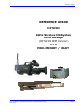
1
Preliminary pages
REFERENCE GUIDE
HITACHI
2GHz Wireless HD System
Fibre Package
(HITACHI OEM Version)
V 1.0
PRELIMINARY / DRAFT
Reference Guide: HITACHI Wireless Camera (HITACHI OEM Version)
March 2010
Page i
Preliminary pages
This document and the information contained in it is the property of
Broadcast Microwave Services Inc. and may be the subject of patents pending and granted. It must not be used for commercial purposes nor copied, disclosed, reproduced, stored in a retrieval system or transmitted in any form or by any means (electronic, mechanical, photocopying, recording or otherwise), whether in whole
or in part, without BMS’s prior written agreement.
© 2009 Broadcast Microwave Services. All rights reserved.
Issue 1 first published in 2010 by:
Broadcast Microwave Services Europe GmbH & Co. KG
Registered Address:
Schwalbacher Straße 12
65321 Heidenrod – Kemel
Germany
Registered Company Number HRA 6230
Reference Guide: HITACHI Wireless Camera (HITACHI OEM Version)
March 2010
Page ii
Preliminary pages
Contents
1
INTRODUCTION
1.1
Preliminary remarks ......................................................................... 1
1.2
Designation .................................................................................... 1
1.3
Delivered items ............................................................................... 1
1
1.4
Application of the HITACHI wireless transmitter .................................. 2
1.4.1
Typical application of the HITACHI fibre system ........................... 2
2
GETTING STARTED
2.1
Safety instructions ........................................................................... 3
2.2
Installing the HITACHI wireless camera components ............................ 3
3
2.3
Connectors ..................................................................................... 3
2.3.1
Antennas................................................................................. 4
2.3.1.1
2.3.1.2
2.3.2
2.3.3
2.3.4
2.3.5
3
UHF Antenna
RF antenna
4
4
Power supply ........................................................................... 4
Intercom headset ..................................................................... 5
Microphones ............................................................................ 5
RS 232 ................................................................................... 5
CONFIGURING THE HITACHI WIRELESS CAMERA DIGITAL TRANSMITTER
5
3.1
Control panel .................................................................................. 5
3.1.1
The LC display ......................................................................... 6
3.1.2
The control buttons................................................................... 6
3.2
Menu structure ................................................................................ 6
3.2.1
Frequency ............................................................................... 8
3.2.2
Software version ...................................................................... 8
3.2.3
Display off ............................................................................... 9
3.2.4
Display brightness ...................................................................10
3.2.5
Data frequency .......................................................................11
3.2.6
Transmission power .................................................................12
3.2.7
Mic Phantom Power..................................................................12
3.2.8
Audio Rear Gain ......................................................................13
3.2.9
Audio Rear Input .....................................................................13
3.2.10 Audio Front Input ....................................................................14
3.2.11 Modulator Setup......................................................................14
3.2.12 Video Setup ............................................................................15
4
CONFIGURING THE HITACHI RECEIVE UNITS
4.1
Connection of the indoor units ..........................................................15
4.2
Installing the DR2500HD Receiver.....................................................16
Reference Guide: HITACHI Wireless Camera (HITACHI OEM Version)
March 2010
15
Page iii
Preliminary pages
4.3
Control buttons and Alarm status at the front of the device.................16
4.3.1
The Display ............................................................................16
4.3.2
The control buttons..................................................................16
4.3.3
Alarm and Status.....................................................................16
4.4
Connectors and indicators at the rear of the device..............................17
5
OPERATING THE DR2500ASI DECODER
5.1
Menu structure ................................................................................ D
5.2
PRESETS ........................................................................................ E
5.3
Frequency assignment...................................................................... F
5.4
Bandwidth selection ......................................................................... G
5.5
Save Preset ..................................................................................... I
5.6
Genlock...........................................................................................J
5.7
Main Sreen ..................................................................................... L
5.8
Contrast .........................................................................................M
5.9
Display OFF ....................................................................................M
5.10
A
Software....................................................................................... N
6
OPERATING THE MODULARX IDU FIBRE
6.1
ModulaRX IDU Fibre Unit................................................................... N
6.2
Menu structure ................................................................................ O
N
UHF transmitter ..................................................................................... P
6.3
Intermodulation distortion................................................................. Q
6.4
Frequency table for data transmission................................................. Q
7
OPERATING THE FIBRE ODU
7.1
Menu structure of Fibre IDU .............................................................. T
7.2
Unlock Keyboard.............................................................................. U
7.3
Frequency RX.................................................................................. U
7.4
Frequency TX .................................................................................. U
7.5
Contrast ......................................................................................... U
7.6
Display OFF .................................................................................... V
Reference Guide: HITACHI Wireless Camera (HITACHI OEM Version)
March 2010
T
Page iv
Preliminary pages
About this Reference Guide
This Reference Guide provides instructions and information for the installation and operation of the HITACHI wireless transmitter. It is not a comprehensive manual for all
camera functions.
This Reference Guide should be kept in a safe place for reference for the life of the
equipment. It is not intended that this Reference Guide will be amended by the issue
of individual pages. Any revision will be by a complete reissue. If passing the equipment to a third party, please also pass on the relevant documentation.
Issues of this Reference Guide are listed below:
Issue
1
Date
Build Version
Comments
March 2010
1.0
Draft
Reference Guide: HITACHI Wireless Camera (HITACHI OEM Version)
March 2010
Page v
Preliminary pages
Warnings, Cautions and Notes
Heed Warnings
All warnings on the product and in the operating instructions should be adhered to.
The manufacturer can not be held responsible for injuries or damage where warnings
and cautions have been ignored or taken lightly.
Read Instructions
All the safety and operating instructions should be read before this product is operated.
Follow Instructions
All operating and use instructions should be followed.
Retain Instructions
The safety and operating instructions should be retained for future reference.
Warning
Warnings give information which, if strictly observed, will prevent personal
injury or death, OR DAMAGE TO PERSONAL PROPERTY OR THE ENVIRONMENT. They are boxed and shaded for emphasis, as in this example, and
are placed immediately preceding the point at which the reader requires
them.
Cautions
Cautions give information which, if strictly followed, will prevent damage to equipment or other goods. They are boxed for emphasis, as in this example, and are
placed immediately preceding the point at which the reader requires them.
Notes
Notes provide supplementary information. They are highlighted for emphasis, as in
this example, and are placed immediately after the relevant text.
Reference Guide: HITACHI Wireless Camera (HITACHI OEM Version)
March 2010
Page vi
Chapter 1: Introduction
Contact Information
BMS Customer Services
Support Services
Our primary objective is to provide first class customer care that is tailored
to your specific business and operational requirements. All levels are supported by one or more service performance reviews to ensure the perfect
partnership between Broadcast Microwave Services and your business.
Warranty
All BMS Products and Systems are designed and built to the highest standards and are covered under a comprehensive 12 month warranty.
Levels of Continuing BMS Service Support
For stand-alone equipment, then Broadcast Microwave Services BASIC
Advantage is the value for money choice for you. BASIC provides you
with year-by-year Service long after the warranty has expired.
For systems support you can choose either GOLD or SILVER Advantage.
These packages are designed to save you costs and protect your income
through enlisting the help of BMS support specialists.
VOYAGER Advantage is the truly mobile service solution. This provides a
package specifically designed to keep you mobile and operational.
Call BMS Sales for more details.
Where to Find Us
Europe:
Tel: + 49-6124-7239-0
Fax: + 49-6124-7239-29
[email protected]
Americas:
Tel: +1-858-391-3050
Fax: +1-858-391-3049
[email protected]
Internet Address:
http://www.bms-inc.com
Reference Guide: HITACHI Wireless Camera (HITACHI OEM Version)
March 2010
Page 1
Chapter 1: Introduction
Technical Training
Training Courses
BMS provides a wide range of training courses on the operation and maintenance of our products and on their supporting technologies. BMS can
provide both regularly scheduled courses and training tailored to individual
needs. Courses can be run either at your premises or at one of our dedicated training facilities.
Where to Find Us
For further information on BMS training programme please contact us:
International Telephone:
+ 49-6124-7239-0 (Europe)
+1-858-391-3050
International Facsimile:
+ 49-6124-7239-29 (Europe)
+1-858-391-3050
E-mail Address:
(America)
(America)
[email protected] (Europe)
[email protected]
Internet Address:
(America)
http://www.bms-inc.com
Customer Services and Technical Training Postal Address
Broadcast Microwave Services Europe GmbH + Co. KG
Schwalbacher Straße 12
65321 Heidenrod–Kemel
Germany
Return of Equipment
If you need to return equipment for repair, please contact
Tel:
+ 49 6124 7239-0
Fax:
+ 49 6124 7239-29
E-mail: [email protected]
Address: see above.
Technical Publications
If you need to contact Broadcast Microwave Services Europe regarding this
publication please e-mail to [email protected]
Reference Guide: HITACHI Wireless Camera (HITACHI OEM Version)
March 2010
Page 2
Chapter 1: Introduction
1 Introduction
1.1 Preliminary remarks
The present document, "Reference Guide, HITACHI Wireless Camera (HITACHI OEM
Version)”, is intended to be used for the proper set-up and operation of the wireless
transmitter unit of the HITACHI camera system.
1.2 Designation
Designation
HITACHI 2GHz Wireless HD System Fibre Package
(HITACHI OEM Version)
Manufacturer:
Broadcast Microwave Services Europe GmbH + Co. KG
1.3 Delivered items
1 x DR2420ODU-Fibre (P/N 12.1617.000)
1 x ModulaRX IDU Fibre (P/N 12.1620.000)
1 x OEM;CW-HD1000 (P/N 11.2501.000)
Reference Guide: HITACHI Wireless Camera (HITACHI OEM Version)
March 2010
Page 1
Chapter 1: Introduction
1.4 Application of the HITACHI wireless transmitter
2x Audio
230VAC
HD-SDI
Genlock
Tally
2 .3
HD
GH
-S
z
DI/
Au
dio
/Da
ta
Data
RX
D
at
45 a T
X
50 5 M (U
0m H H
W z) F
1.4.1 Typical application of the HITACHI fibre system
Figure 1: Typical Application
Reference Guide: HITACHI Wireless Camera (HITACHI OEM Version)
March 2010
Page 2
Chapter 3: Operating the equipment
2 Getting started
2.1 Safety instructions
Warning
The regulations of VDE0100 must be observed for installation and operation of the unit.
Caution
• Before powering up the camera for the first time make sure all connections are
completed.
• Pay attention to all warnings in this document.
• Make sure that the ventilation openings of the camera are not obstructed to ensure efficient heat dissipation.
• The camera should be protected against moisture and humidity.
2.2 Installing the HITACHI wireless camera components
The wireless transmitter of the HITACHI camera is integrated into the camera housing.
2.3 Connectors
Please make sure you connect all antennas and cables to the below described connector jacks.
Reference Guide: HITACHI Wireless Camera (HITACHI OEM Version)
March 2010
Page 3
Chapter 3: Operating the equipment
2.3.1 Antennas
Figure 2: Antenna Sockets
2.3.1.1 UHF Antenna
Socket number 1 in Figure 2 is the UHF input for the intercom connection. To this
socket a 50-Ohm UHF antenna must be mounted.
2.3.1.2 RF antenna
Connect an active RF antenna to socket number 2 in Figure 2. You may need to apply
an N-N adaptor. The impedance is 50 Ohm.
Caution
If you wish to connect other than the specified components (eg power amplifier or
passive antennas) a DC blocker must be applied. Otherwise, your HITACHI Wireless Camera and/or other connected equipment may be damaged.
Note
The HF output supplies 5 VDC for an active antenna.
2.3.2 Power supply
Most likely, your camera will be fed by a rechargeable battery. A V-mount bracket on
the back side of the camera supports the battery housing.
Reference Guide: HITACHI Wireless Camera (HITACHI OEM Version)
March 2010
Page 4
Chapter 3: Operating the equipment
If you desire to use an external power supply, you will find a 4-pole XLR 12 VDC input
on the back side of the camera. As When connected to an external power supply the
camera will switch from battery operation to the external power supply.
2.3.3 Intercom headset
Connect the intercom headset to the 5-pole XLR socket on the back side of you camera.
2.3.4 Microphones
The HITACHI Wireless Camera is equipped with two microphone input sockets on the
back side. Connect your external microphones to these 3-pole XLR connectors.
2.3.5 RS 232
For servicing (eg software updates of the control panel) the wireless transmitter unit
of the camera you may need to connect a PC to the RS 232 socket found below the
control panel.
3 Configuring the HITACHI wireless camera digital transmitter
3.1 Control panel
The digital transmitter unit of your HITACHI wireless camera is equipped with a control panel including control buttons and an LC display.
Figure 3: Transmitter Unit Control Panel
The control panel allows you to easily adjust the settings of the digital transmitter unit
of your HITACHI Wireless Camera.
Reference Guide: HITACHI Wireless Camera (HITACHI OEM Version)
March 2010
Page 5
Chapter 3: Operating the equipment
Note
While configuring the digital transmitter you must not disconnect the power supply
from the camera. This may cause loss of presets.
3.1.1 The LC display
The HITACHI Wireless Camera digital transmitter unit is equipped with an LC display.
This display simplifies the configuration.
T.
MHz
Figure 4: LC Display
Unless you are adjusting your transmitter parameters, the display shows the signal
strength of the received camera control UHF signal in the upper left corner, an error
code in the upper right corner and the adjusted transmitting frequency of the video
and audio signal.
3.1.2 The control buttons
The control buttons are located below the LC display on the control panel. These buttons are used for the navigation through the different menu items. Depending on the
parameter to be changed the operator can use the control buttons “Up”/”Down”
and/or “Left”/”Right”.
Figure 5: Control Buttons
3.2 Menu structure
After you switched on the HITACHI Wireless Camera the control panel of the digital
transmitter unit shows an initialisation message. Once the initialisation phase has finished the main display (see Figure 4) is shown. Now you can access to the menu and
adjust the different settings.
Reference Guide: HITACHI Wireless Camera (HITACHI OEM Version)
March 2010
Page 6
Chapter 3: Operating the equipment
T.
6500
MHz
2328.000
MHz
Figure 6: Menu Structure
Reference Guide: HITACHI Wireless Camera (HITACHI OEM Version)
March 2010
Page 7
Chapter 3: Operating the equipment
3.2.1 Frequency
On the main display, press the button “OK” for approximately 3 seconds. The current
frequency is shown.
FREQUENCY
MHz
Figure 7: Frequency Menu
After pressing “OK” another time for approximately 3 seconds the first digit of the frequency is highlighted and the display looks like shown in Figure 8. Press the “UP” control button to increase the value or the “DOWN” control button to decrease. To move
to the next digit press the “RIGHT” control button or press the “LEFT” control button
to jump back to the previous digit. Now adjust the frequency you wish to use.
FREQUENCY
Figure 8: Adjusting the Frequency
To confirm the selected frequency press the “OK” button and the main menu will be
shown.
3.2.2 Software version
The control panel gives you the opportunity to show the recently installed software
version. On the main display, press again the button “OK” for approximately 3 seconds. The current frequency is shown. Now use the “UP”/”DOWN” buttons to go to the
“SOFTWARE” menu.
No further adjustments can be made. The LC display shows the software version.
Reference Guide: HITACHI Wireless Camera (HITACHI OEM Version)
March 2010
Page 8
Chapter 3: Operating the equipment
SOFTWARE
Figure 9: Software Version Display
3.2.3 Display off
In certain production environments you may want to switch the LC display off.
On the main display, press the button “OK” for approximately 3 seconds. The current
frequency is shown. Now use the “UP”/”DOWN” buttons to go to the “DISPLAY OFF”
menu.
DISPLAY OFF
Figure 10: Display Off Menu
Press the “OK” button again for approximately 3 seconds and the current display-off
time level is highlighted. Use the “UP”/”DOWN” buttons in order to increase or decrease the display brightness in a range from 0 to 240 seconds in steps of 15 seconds.
This is the time your display switches off after no button was pressed on the control
panel. If you adjust the value to 0 seconds the display remains switched on.
DISPLAY OFF
Figure 11: Display-off Time Adjustment
To confirm the selected display-off time press the “OK” button and the main menu will
be shown.
Note
Once the display is switched off simply by pressing the “OK” button for
Reference Guide: HITACHI Wireless Camera (HITACHI OEM Version)
March 2010
Page 9
Chapter 3: Operating the equipment
approximately 3 seconds it switches on again and you can use the menu. After the
previously adjusted time without any action the display automatically switches off
again.
3.2.4 Display brightness
You may wish to adjust the brightness of the LC display to your production environment.
On the main display, press the button “OK” for approximately 3 seconds. The current
frequency is shown. Now use the “UP”/”DOWN” buttons to go to the “CONTRAST”
menu.
CONTRAST
Figure 12: Contrast Menu
Press the “OK” button again for approximately 3 seconds and the current contrast
level is highlighted. Use the “UP”/”DOWN” buttons in order to increase or decrease the
display brightness in a range from 0 to 15. 0 is the darkest adjustment, 15 the highest brightness.
CONTRAST
Figure 13: Display Brightness Adjustment
Reference Guide: HITACHI Wireless Camera (HITACHI OEM Version)
March 2010
Page 10
Chapter 3: Operating the equipment
To confirm the selected brightness level press the “OK” button and the main menu will
be shown.
3.2.5 Data frequency
The camera may be connected to a CCU via an UHF wireless connection. In the “DATA
FREQUENCY” menu you have the possibility to adjust the frequency of the channel.
On the main display, press the button “OK” for approximately 3 seconds. The current
frequency is shown. Now use the “UP”/”DOWN” buttons to go to the “DATA FREQUENCY” menu.
DATA FREQUENCY
Figure 14: Data Frequency Menu
After pressing “OK” another time for approximately 3 seconds the data frequency is
shown red. Use the control buttons to adjust the frequency in steps of 0.01 MHz.
DATA FREQUENCY
Figure 15: Adjusting the Data Frequency
To confirm the selected frequency press the “OK” button and the main menu will be
shown.
Reference Guide: HITACHI Wireless Camera (HITACHI OEM Version)
March 2010
Page 11
Chapter 3: Operating the equipment
3.2.6 Transmission power
In order to trim the transmission power to your environment you can choose between
three preset power levels in the “OUTPUT POWER” menu.
On the main display, press the button “OK” for approximately 3 seconds. The current
frequency is shown. Now use the “UP”/”DOWN” buttons to go to the “OUTPUT POWER”
menu.
OUTPUT POWER
Figure 16: Output Power Menu
Press the “OK” button again for approximately 3 seconds and the current output
power level is highlighted. With the “UP”/”DOWN” control buttons you can choose between low, medium and high transmission power.
OUTPUT POWER
MEDIUM
LOW
Figure 17: Output Power Adjustment
(Low=10mW; Medium=100mW; High=400mW).To confirm the selected power level
press the “OK” button and the main menu will be shown.
3.2.7 Mic Phantom Power
The control panel gives you the opportunity to enable the MIC phantom power if “MIC”
is selected in the menu “AUDIO REAR INPUT”.
MIC PHANTOM POWER
Figure 13: Software Version Display
Reference Guide: HITACHI Wireless Camera (HITACHI OEM Version)
March 2010
Page 12
3.2.8 Audio Rear Gain
If you connect an audio signal to the “Rear Audio” connector at the back of the camera, then you can adjust the gain of the signal. In order to adjust the audio gain you
can choose between the values +30….-10dB in the “AUDIO REAR GAIN” menu.
On the main display, press the button “OK” for approximately 3 seconds. The current
frequency is shown. Now use the “UP”/”DOWN” buttons to go to the “AUDIO REAR
GAIN” menu.
AUDIO REAR GAIN
Figure 14: Audio Rear Gain
Press the “OK” button again for approximately 3 seconds and the current gain level is
highlighted. With the “UP”/”DOWN” control buttons you can choose between the values +30….-10dB.
3.2.9 Audio Rear Input
In order to select the audio input you can choose between “LINE” and “MIC”
On the main display, press the button “OK” for approximately 3 seconds. The current
frequency is shown. Now use the “UP”/”DOWN” buttons to go to the “AUDIO REAR INPUT”” menu.
AUDIO REAR INPUT
Figure 15: Audio Rear Input
Press the “OK” button again for approximately 3 seconds and the current input is
highlighted. With the “UP”/”DOWN” control buttons you can choose between “MIC”
and “LINE”.
Reference Guide: HITACHI Wireless Camera (HITACHI OEM Version)
March 2010
Page 13
Note
If you select “LINE” you will not see the “MIC PHANTOM POWER” sub menu
3.2.10
Audio Front Input
Having VF SETUP selected in this sub menu you will be able to adjust the audio of the
front microfone through the viewfinder menu.
AUDIO FRONT INPUT
Figure 16: Audio Front Input
3.2.11
Modulator Setup
This setup shows you the current modulation of the transmitter. It is not possible to
change something.
MODULATOR SETUP
FEC 2/3
GUARD 1/32
Figure 17: Modulator Setup
Reference Guide: HITACHI Wireless Camera (HITACHI OEM Version)
March 2010
Page 14
3.2.12
Video Setup
This setup shows you the current video parameters. It is not possible to change something.
VIDEO SETUP
29,97 fps
Figure 17: Modulator Setup
4 Configuring the HITACHI Receive units
4.1 Connection of the indoor units
In the figure 18 you can see how to connect the devices with the delivered cables.
5
9
4
8
3
7
2
6
1
17.1165.401
Figure 18: How to connect the cables to the devices
Reference Guide: HITACHI Wireless Camera (HITACHI OEM Version)
March 2010
Page 15
4.2 Installing the DR2500HD Receiver
The DR2505-ASI decoder can be accommodated in a 19" rack with a height of 1 RU.
4.3 Control buttons and Alarm status at the front of the
device
4.3.1 The Display
A LC display is used to show the RF and COFDM parameters and the configuration parameters.
DR2500-ASI
MER/dB
1:
2:
00
00
Status: Unlocked
Const: --
FEC: --
01
2349.00MHz
Guard: --
Figure
1 :19:
LCD
Figure
LCDDisplay
Display
4.3.2 The control buttons
The control buttons are located on the right side of the front panel. They allow navigation of the different receiver DR2500HD menus. Depending on the parameter to be
changed the operator can use the control buttons “UP”/”Down” and/or “Left”/”Right”
OK
Figure 2 Figure
: Control
20:buttons
Control buttons
4.3.3 Alarm and Status
Lights up, when the tuned Frequency differs from the allowed Frequency range of the
receiver (Fibre-ODU). The DR2500-ASI switches automatically to the next highest or
lowest adjustable Frequency.
Lights up, when the DR2500ASI doesn’t receive any signals (Unlocked). Once a signal
is received, the light switches off.
Reference Guide: HITACHI Wireless Camera (HITACHI OEM Version)
March 2010
Page 16
Lights up, when the DR2500-ASI is powered by the power supply.
4.4 Connectors and indicators at the rear of the device
ASI in
Genlock
HD-SDI
L
Audio
R
µPC/Data
12VDC
AUX
HD-SDI
Figure 3
21::Rear
of the
Figure
Rear
ofDR2500ASI
the DR2500HD Diversity Receiver
At the rear of the DR2500HD Diversity Receiver:
•
1 X “ASI in”, this is the ASI signal which comes from the Fibre-IDU
•
1 X “Genlock in” for Synchronization [SD- or HD-SDI], BNC female
•
2 X “SDI out” for video, BNC female
•
1 X "12-18V-DC" 4-pol XLR connector for 12-18V DC power supply
•
“Ant.1” and “Ant.2”are 2 X SMA (f) sockets for RF input
•
1 X “uPC/Data” is a Serial 9 pin Sub-D (f) socket for remote control RX and data
output
•
“Audio L” and “Audio R” are 3-pol XLR connector for audio out
Caution
Be sure that the ventilation openings are not obstructed.
Reference Guide: HITACHI Wireless Camera (HITACHI OEM Version)
March 2010
Page 17
5 Operating the DR2500ASI decoder
When the DR2500ASI is connected to a power supply, the display at the front of the
unit will light up.
During the initialisation phase, the company’s name, receiver’s name as well as the
software version are displayed.
The operation of the unit is controlled using the control elements located at the front
panel.
BMS inc
DR2500-ASI
v2.04
Figure 4 : Initialisation phase
Figure 22: Initalisation phase
After that the initialisation phase is done the receiver switches automatically to the
“Main Display” see Figure 6.
DR2524-HD
MER/dB
1:
2:
22
24
Status: Locked
Const: 64QAM
FEC: 2/3
01
2349.00MHz
GL (AUTO)
Guard: 1/32
Figure
5 :23:Main
Display
Figure
Main display
In case that there is good transmission at the set frequency, you will get the overview
displayed like in the Picture shown in “Figure 6”
On top of the right side you can see the model name of the receiver and under the
model name are displayed the selected preset and the frequency which is stored in
that preset.
On the left side the bar graph for the MER value is shown. In “Figure 6” the bar graph
value would be 0 in case of bad reception, because no transmission is received at the
moment by the receiver. Bar graph “1:” shows the MER from antenna 1 and “2:”
shows the value from antenna 2.
Reference Guide: HITACHI Wireless Camera (HITACHI OEM Version)
March 2010
Page A
Note
The modulation error ratio (MER) is a measure of the SNR in a digitally modulated
signal. Like SNR, MER can be expressed in dB.
Signal-to-noise (SNR or S/N) is an electrical engineering measurement, defined as
the ratio of a signal power to the noise power corrupting the signal. Signal-tonoise ratio compares the level of a desired signal to the level of background noise.
The higher the ratio, the less obtrusive the background noise is.
•
Status:
Unlocked : will be displayed when any signal is received
Locked : will be displayed when a signal is received
At the bottom of the display the Constellation, FEC and Guard Interval will be shown
automatically, if a signal is received and decoded by the receiver.
•
Guard: 1/4, 1/8, 1/16, 1/32 can be displayed depending on the bandwidth of
the transmitted signal
In COFDM, the beginning of each symbol is preceded by a guard interval. As long as the
echoes fall within this interval, they will not affect the receiver's ability to safely decode the
actual data, as data is only interpreted outside the guard interval.
Longer guard periods allow more distant echoes to be tolerated. However, longer guard
intervals reduce the channel efficiency. In DVB-T, four guard intervals are available (given
as fractions of a symbol period): 1/32 ; 1/16 ; 1/8 ; 1/4
Hence, 1/32 gives lowest protection and the highest data rate. 1/4 results in the best
protection but the lowest data rate
•
FEC: 1/2, 2/3, 3/4, 5/6 can be displayed depending on the FEC of the transmitted signal
Forward Error Correction (FEC) is a system of error control for data transmission, whereby
the sender adds redundant data to its messages, also known as an error-correction code.
This allows the receiver to detect and correct errors (within some bound) The advantage of
forward error correction is that a back-channel is not required, at the cost of higher bandwidth requirements on average.
Reference Guide: HITACHI Wireless Camera (HITACHI OEM Version)
March 2010
Page B
•
Const: QPSK, 16 QAM, 64 QAM can be displayed depending on the modulation
mode of the transmitted signal
Constellation (DVB-T Modulation) mode can be between QPSK, 16QAM and 64QAM.
QPSK is the default mode (in SD transmission) and will give the strongest most rugged RF
link performance. Selecting 16QAM reduces the link performance by 5dB but improves the
link data throughput, giving significantly better video quality. 64QAM is the constellation
mode for HD transmission due to the high data rate.
Reference Guide: HITACHI Wireless Camera (HITACHI OEM Version)
March 2010
Page C
5.1 Menu structure
D R 2 5 2 4-H D
M E R /d B
1:
2:
S tatu s: L o cked
C o nst: 64Q A M
22
24
F E C : 2/3
01
2 3 4 9.0 0M H z
G L (A U T O )
G u ard : 1/32
M a in S cre e n
PRESET
P R E S E T 1 … ...P R E S E T 2 6
FREQ UENCY
T ra n sm issio n fre q u e n cy se t
B A N D W ID T H
6M Hz / 7M H z / 8M Hz
SAVE PRESET
YES / NO
G ENLO CK
O FF / AUTO / O N
M a in S c re e n
F R E Q U E N C Y / M E R in d B
CO NTRAST
0 0 0 ...1 2 7
D IS P L A Y O F F
0 0 0 ...2 4 0 se co n d s
SO FTW ARE
S o ftw a re V e rsio n
Reference Guide: HITACHI Wireless Camera (HITACHI OEM Version)
March 2010
Page D
5.2 PRESETS
Press the button “OK” for 2-3 seconds to enter the main menu.
The first submenu is the “PRESET”-menu, where it is possible to select 26 different
presets. Each preset can contain a different frequency which the customer can assign
due to his needs.
DR2500-ASI
PRESET
01
2349.00MHz
To change the preset number press again the button “OK” for 2-3 seconds to be able
to change the preset. Two small triangle will show that the change mode is activated.
DR2500-ASI
PRESET
01
2349.00MHz
Now it is possible to select with the UP/DOWN button 1 of 26 presets. To confirm the
selected preset press the “OK” button and after that it will appear “UPDATING DEVICE”.
DR2500-ASI
PRESET
26
UPDATING DEVICE
Note
A quick button press will return you to the previous menu to effect and save the
changes and another quick press takes you away from the main menu
Reference Guide: HITACHI Wireless Camera (HITACHI OEM Version)
March 2010
Page E
5.3 Frequency assignment
Press the button “OK” for 2-3 seconds to enter in the main menu and one time the
right button for the frequency option. This menu gives the user the possibility to set
the frequency manually without using the preset option.
DR2500-ASI
FREQUENCY
2385.00MHZ
Press again the button “OK” for 2-3 seconds to be able to change the frequency
range. After pressing “OK” for the second time the first digit is highlighted and the
display looks like in figure 7. Press the “UP” control button to increase the digit and
the “DOWN” to decrease, to move to the second digit press the “RIGHT” control button or Press the “LEFT” to come back to the previous digit.
DR2500-ASI
FREQUENCY
22385.00MHZ
To confirm the frequency press the “OK” button and after that it will appear “UPDATING DEVICE”.
DR2500-ASI
FREQUENCY
2385.00
MHZ
UPDATING DEVICE
Reference Guide: HITACHI Wireless Camera (HITACHI OEM Version)
March 2010
Page F
Note
A quick button press will return you to the previous menu to effect and save the
changes and another quick press takes you away from the main menu
DR2500-ASI
MER/dB
1:
2:
Status: Locked
Const: 64QAM
**
22
24
FEC: 2/3
2388.00MHz
GL (AUTO)
Guard: 1/32
At the position where normally the preset number is shown, there are displayed two
stars “**”, which is an indication for the user, that no preset is set, but a manually
frequency.
5.4 Bandwidth selection
Press the button “OK” for 2-3 seconds to enter the main menu.
The third submenu is the “BANDWIDTH”-menu, where it is possible to select 3 different bandwidth (6 / 7 / or 8 MHz). Before changing the bandwidth, please check the
bandwidth setting of your transmitter.
DR2500-ASI
BANDWIDTH
8 MHz
Note
For HD transmission you have to set the bandwidth to 8 MHz.
Reference Guide: HITACHI Wireless Camera (HITACHI OEM Version)
March 2010
Page G
To change the bandwidth press again the button “OK” for 2-3 seconds to be able to
change the setting. Two small triangle will show that the change mode is activated.
DR2500-ASI
BANDWIDTH
8 MHz
Now it is possible to select with the UP/DOWN button the bandwidth of the transmitted signal you want to receive. To confirm the selected preset press the “OK” button
and after that it will appear “UPDATING DEVICE”.
DR2524-HD
BANDWIDTH
8 MHz
UPDATING DEVICE
Note
A quick button press will return you to the previous menu to effect and save the
changes and another quick press takes you away from the main menu
Reference Guide: HITACHI Wireless Camera (HITACHI OEM Version)
March 2010
Page H
5.5 Save Preset
If a frequency has been set in the “Frequency” option, described in Chapter 3.3, it is
possible to save this frequency in one of the 26 Preset options. To save a frequency in
a Preset, follow the steps:
1. Select the Preset you want to store the new frequency (Chapter 3.2)
2. Set the new frequency (Chapter 3.3)
3. Save preset:
Press the button “OK” for 2-3 seconds to enter in the main menu and two times
the right button for the “SAVE PRESET” option.
DR2524-HD
SAVE PRESET
?
Reference Guide: HITACHI Wireless Camera (HITACHI OEM Version)
March 2010
Page I
This menu gives the user the possibility to save a frequency under the current preset.
Now press again the button “OK” for 2-3 seconds and you will have the choice between “YES” (to save frequency to current preset) and press the OK button.
DR2524-HD
SAVE PRESET
YES
Now the frequency is stored to the preset.
5.6 Genlock
If a genlock is used with the DR2500HD receiver, the user will have some options to
set the genlock function.
Press the button “OK” for 2-3 seconds to enter in the main menu and three times the
right button for the “GENLOCK” option and press again the “OK” button for 2-3 seconds. Press the “UP” or “DOWN” control button to select one of the three options
which are given to the user in this menu: OFF / AUTO / ON
1) OFF – the receiver will not use any external genlock
DR2524-HD
MER/dB
1:
2:
Status: Locked
Const: 64QAM
**
22
24
FEC: 2/3
2388.00MHz
Guard: 1/32
Reference Guide: HITACHI Wireless Camera (HITACHI OEM Version)
March 2010
Page J
2) ON - the receiver will use the external genlock
DR2524-HD
MER/dB
1:
2:
**
22
24
Status: Locked
Const: 64QAM
FEC: 2/3
2388.00MHz
GL=Genlock „ON“
GL
Guard: 1/32
Note
If Genlock “ON” is selected but no Genlock signal is present, the decoder will not
be able to decode any signal
3) AUTO – the receiver will detect automatically if an external genlock is connected
DR2524-HD
MER/dB
1:
2:
Status: Locked
Const: 64QAM
**
22
24
FEC: 2/3
2388.00MHz
GL=Genlock „AUTO“
GL (AUTO)
Guard: 1/32
Now press again the button “OK” for 2-3 seconds to confirm your choice.
Reference Guide: HITACHI Wireless Camera (HITACHI OEM Version)
March 2010
Page K
5.7 Main Sreen
It is possible to choose between two Main Screens. Press the button “OK” for 2-3 seconds to enter in the main menu and four times the right button for the “Main Screen”
option and press again the “OK” button for 2-3 seconds. Press the “UP” or “DOWN”
control button to select one of the two options: Frequency or MER in dB.
1) Main Screen (FREQUENCY)
DR2524-HD
FREQUENCY
2385.00MHZ
In this display you will get only the frequency displayed and the device model.
2) Main Screen (MER in dB)
DR2524-HD
MER/dB
1:
2:
22
24
Status: Locked
Const: 64QAM
FEC: 2/3
01
2349.00MHz
GL (AUTO)
Guard: 1/32
The display shows you different information at the same time:
-
MER/dB for antenna1 and antenna 2
-
Status of incoming signal (locked or unlocked)
-
Modulation of received and decoded Signal (QPSK/16QAM/64QAM)
-
FEC (1/2;2/3;4/4;5/6;7/8)
-
Guard interval (1/4;1/8;1/16;1/32)
-
Genlock setting ( AUTO])
-
Preset number and frequency (if preset is selected) or only frequency if no preset is selected
[Genlock OFF]; GL [Genlock ON]; GL (AUTO); [Genlock
Reference Guide: HITACHI Wireless Camera (HITACHI OEM Version)
March 2010
Page L
5.8 Contrast
Press the button “OK” for 2-3 seconds to enter in the main menu, and then press
twice the control button “RIGHT” to select the sub menu “CONTRAST”.
Press again the button “OK” for 2-3 seconds and then press the control button “UP” or
“DOWN” to choose between a range from 000 to 127. The higher the digit the brighter
the display.
DR2524-HD
CONTRAST
010
Note
A quick button press short will return you to the previous menu and save the
changes. A quick button press exits the main menu
5.9 Display OFF
Press the button “OK” for 2-3 seconds to enter in the main menu, then press three
times the control button “RIGHT” to select the sub menu “DISPLAY OFF”.
Press again the button “OK” for 2-3 seconds and then press the control button “UP” or
“DOWN” to choose between 000s to 240s. The user can choose the time after which
the unit would automatically switch off the display.
DR2524-HD
Display OFF
000
Reference Guide: HITACHI Wireless Camera (HITACHI OEM Version)
March 2010
Page M
Note
A quick button press will return you to the previous menu and save the changes
Another quick press exits the main menu.
5.10
Software
Press the button “OK” for 2-3 seconds to enter in the main menu, then press four
times control button “RIGHT” control button to navigate in the main menu and select
the “SOFTWARE”.
The software version will be displayed.
DR2524-HD
SOFTWARE
V2.04
Note
A quick press returns you to the main menu
6 Operating the ModulaRX IDU Fibre
6.1 ModulaRX IDU Fibre Unit
IDU RX
RCP: OK
CAM: OK
DATA-TX:
DATA-RX:
Reference Guide: HITACHI Wireless Camera (HITACHI OEM Version)
March 2010
DataTX
465.53MHz/CH129
UHF-DATA: OK
COFDM-DATA:OK
Page N
6.2 Menu structure
ID U R X
RCP: OK
CAM: OK
D A T A -T X :
D A T A -R X :
D a ta T X
4 6 5 .5 3 M H z/C H 1 2 9
U H F -D A T A : O K
C O F D M -D A T A :O K
M a in S cre e n
D A T A -F R E Q U E N C Y
M A IN S C R E E N
CO NTRAST
D IS P L A Y O F F
SO FTW ARE
Alarm and Status
The following chapter describes the meaning of the different status of the unit.
DataTX
Shows the current frequency from the data transmitter which is inbuilt into the outdoor unit.
COFDM o.k.
“OK” lights up, when the transmission between the camera transmitter and the Fibre
ODU Diversity receiver is properly.
When “fail” appears, please check the transmission between the CT2020 transmitter
and the diversity receiver.
UHF o.k.
“OK” lights up, when the transmission between UHF transmitter and the camera
transmitter is properly.
When “fail” appears, please check if all cables are properly connected at the UHF
transmitter site.
Data-TX
Lights up, when data is transmitted to the camera
Light up permanently only when data are transmitted.
Reference Guide: HITACHI Wireless Camera (HITACHI OEM Version)
March 2010
Page O
RCP
Lights up, when the RCP is not connected or configured wrong
In normal mode the light should be switched off
Camera
“OK” lights up, when the Camera is transmitting
“FAIL” will show a problem with the transmitter.
UHF transmitter
To power supply the UHF transmitter, connect the 12VDC power supply to the 4-XLR
(m) connector of the UHF transmitter.
Connect the “DATA IN” by using the BNC cable from the OCP Interface “DATA out”.
UHF frequency set up
Press the button (o) for to enter in the main menu and a second time to change the
frequency. Then set up the frequency using the “up” and “down” control buttons.
Reference Guide: HITACHI Wireless Camera (HITACHI OEM Version)
March 2010
Page P
6.3 Intermodulation distortion
Intermodulation distortion, commonly known as Intermods, is a type of interference
that can occur in any non-linear junction. It exists when more than one signal is present at the same time. These fundamentals signals, known as carrier signals, can
combine to create new, unwanted frequencies resulting in interference. E.g. using
many UHF transmitters at the same time can produce intermodulation interference.
To avoid the third order intermodualtion interference and/or near far problem, which
can be an issue when many channels are being used in the same area. We recommend to create a channel plan by using software packages which can assist in calculating intermodulation products.
6.4 Frequency table for data transmission
Kanal
1
2
3
4
5
6
7
8
9
10
11
12
13
14
15
16
17
18
19
20
21
22
23
24
25
26
27
28
29
30
31
32
33
Frequenz
[MHz]
455,8500
455,8600
455,8700
455,8800
455,8900
455,9000
455,9100
455,9200
455,9300
455,9400
455,9500
455,9600
455,9700
455,9800
455,9900
456,0000
456,0100
456,0200
456,0300
456,0400
456,0500
456,0600
456,0700
456,0800
456,0900
456,1000
456,1100
456,1200
456,1300
456,1400
456,1500
456,1600
456,1700
Kanal
129
130
131
132
133
134
135
136
137
138
139
140
141
142
143
144
145
146
147
148
149
150
151
152
153
154
155
156
157
158
159
160
161
Reference Guide: HITACHI Wireless Camera (HITACHI OEM Version)
March 2010
Frequenz
[MHz]
465,5300
465,5400
465,5500
465,5600
465,5700
465,5800
465,5900
465,6000
465,6100
465,6200
465,6300
465,6400
465,6500
465,6600
465,6700
465,6800
465,6900
465,7000
465,7100
465,7200
465,7300
465,7400
465,7500
465,7600
465,7700
465,7800
465,7900
465,8000
465,8100
465,8200
465,8300
465,8400
465,8500
Page Q
34
35
36
37
38
39
40
41
42
43
44
45
46
47
48
49
50
51
52
53
54
55
56
57
58
59
60
61
62
63
64
65
66
67
68
69
70
71
72
73
74
75
76
77
78
79
80
81
82
83
84
85
86
87
88
456,1800
456,1900
456,2000
456,2100
456,2200
456,2300
456,2400
456,2500
456,2600
456,2700
456,2800
456,2900
456,3000
456,3100
456,3200
456,3300
456,3400
456,3500
456,3600
456,3700
456,3800
456,3900
456,4000
456,4100
456,4200
456,4300
456,4400
456,4500
456,4600
456,4700
456,4800
456,4900
456,5000
456,5100
456,5200
456,5300
456,5400
456,5500
456,5600
456,5700
456,5800
456,5900
456,6000
456,6100
456,6200
456,6300
456,6400
456,6500
456,6600
456,6700
456,6800
456,6900
456,7000
456,7100
456,7200
162
163
164
165
166
167
168
169
170
171
172
173
174
175
176
177
178
179
180
181
182
183
184
185
186
187
188
189
190
191
192
193
194
195
196
197
198
199
200
201
202
203
204
205
206
207
208
209
210
211
212
213
214
215
216
Reference Guide: HITACHI Wireless Camera (HITACHI OEM Version)
March 2010
465,8600
465,8700
465,8800
465,8900
465,9000
465,9100
465,9200
465,9300
465,9400
465,9500
465,9600
465,9700
465,9800
465,9900
466,0000
466,0100
466,0200
466,0300
466,0400
466,0500
466,0600
466,0700
466,0800
466,0900
466,1000
466,1100
466,1200
466,1300
466,1400
466,1500
466,1600
466,1700
466,1800
466,1900
466,2000
466,2100
466,2200
466,2300
466,2400
466,2500
466,2600
466,2700
466,2800
466,2900
466,3000
466,3100
466,3200
466,3300
466,3400
466,3500
466,3600
466,3700
466,3800
466,3900
466,4000
Page R
89
90
91
92
93
94
95
96
97
98
99
100
101
102
103
104
105
106
107
108
109
110
111
112
113
114
115
116
117
118
119
120
121
122
123
124
125
126
127
128
456,7300
456,7400
456,7500
456,7600
456,7700
456,7800
456,7900
456,8000
456,8100
456,8200
456,8300
456,8400
456,8500
456,8600
456,8700
456,8800
456,8900
456,9000
456,9100
456,9200
456,9300
456,9400
456,9500
456,9600
456,9700
456,9800
456,9900
457,0000
457,0100
457,0200
457,0300
457,0400
457,0500
457,0600
457,0700
457,0800
457,0900
457,1000
457,1100
457,1200
217
218
219
220
221
222
223
224
225
226
227
228
229
230
231
232
233
234
235
236
237
238
239
240
241
242
243
244
245
246
247
248
249
250
251
252
253
254
255
256
Reference Guide: HITACHI Wireless Camera (HITACHI OEM Version)
March 2010
466,4100
466,4200
466,4300
466,4400
466,4500
466,4600
466,4700
466,4800
466,4900
466,5000
466,5100
466,5200
466,5300
466,5400
466,5500
466,5600
466,5700
466,5800
466,5900
466,6000
466,6100
466,6200
466,6300
466,6400
466,6500
466,6600
466,6700
466,6800
466,6900
466,7000
466,7100
466,7200
466,7300
466,7400
466,7500
466,7600
466,7700
466,7800
466,7900
466,8000
Page S
7 Operating the Fibre ODU
7.1 Menu structure of Fibre IDU
LOC KED
2 3 2 8 .0 0 0
MHZ
M a in S cre e n
FREQ UENCY RX
FREQ UENCY TX
CO NTRAST
D IS P L A Y O F F
SO FTW ARE
Reference Guide: HITACHI Wireless Camera (HITACHI OEM Version)
March 2010
Page T
7.2 Unlock Keyboard
To be able to enter the submenu you must unlock the keyboard. Press the two arrow
buttons at the same time to unlock the keyboard
7.3 Frequency RX
In this menu you can set the frequency for the reception of the camera signal.
Press the button (o) for 2-3 seconds to enter in the main menu and a second time to
change the frequency. Then set up the RX frequency using the “up” and “down” control buttons. Please be sure that the frequency you set is the same frequency the
camera is transmitting.
7.4 Frequency TX
In this menu you can set the frequency for the data transmitter for the remote control
of the camera.
Press the button (o) for 2-3 seconds to enter in the main menu and a second time to
change the frequency. Then set up the frequency using the “up” and “down” control
buttons.
7.5 Contrast
Press the button (o) for 2-3 seconds to enter in the main menu and a second time to
change the contrast of the display.
Press again the button (o) for 2-3 seconds and then press the control button “UP” or
“DOWN” to choose between a range from 000 to 127. The higher the digit the brighter
the display.
Reference Guide: HITACHI Wireless Camera (HITACHI OEM Version)
March 2010
Page U
7.6 Display OFF
Press the button (o) for 2-3 seconds to enter in the main menu and a second time to
change the display off value.
Press again the button “OK” for 2-3 seconds and then press the control button “UP” or
“DOWN” to choose between 000s to 240s. The user can choose the time after which
the unit would automatically switch off the display.
Reference Guide: HITACHI Wireless Camera (HITACHI OEM Version)
March 2010
Page V