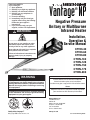
1
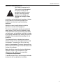
FOR YOUR SAFETY If you smell gas: 1. Open windows. 2. DO NOT try to light any appliance. 3. DO NOT use electrical switches. 4. DO NOT use any telephone in your building. 5. Leave the building. 6. Immediately call your local gas supplier after leaving the building. Follow the gas suppliers instructions. 7. If you cannot reach your gas supplier, call the Fire Department. WARNING Vantage NP ® Negative Pressure Unitary or Multiburner Infrared Heater Installation, Operation & Service Manual Fire Hazard Do not store or use gasoline or other flammable vapors and liquids in the vicinity of this or any other appliance. CTHN-40 CTHN-60 CTHN-80 CTHN-100 CTHN-125 CTHN-150 CTHN-175 CTHN-200 Some objects will catch fire or explode when placed close to heater. Failure to follow these instructions can result in death, injury or property damage. WARNING Improper installation, adjustment, alteration, service or maintenance can result in death, injury or property damage. Read the Installation, Operation and Service Manual thoroughly before installing or servicing this equipment. Installation must be done by a contractor qualified in the installation and service of gas-fired heating equipment or your gas supplier. Installer Please take the time to read and understand these instructions prior to any installation. Installer must give a copy of this manual to the owner. Owner Keep this manual in a safe place in order to provide your serviceman with necessary information. Roberts-Gordon, LLC 1250 William Street P.O. Box 44 Buffalo, New York 14240-0044 Telephone: 716.852.4400 Fax: 716.852.0854 Toll Free: 800.828.7450 Quality in Any Language™ © Copyright 2006 Roberts-Gordon, LLC www.rg-inc.com P/N 152101NA Orig 06/06 TABLE OF CONTENTS SECTION 1: Heater Safety...................................................... 1 1.1 Manpower Requirements ............................................. 1 SECTION 2: Installer Responsibility ..................................... 2 2.1 Wall Tag ....................................................................... 2 2.2 Corrosive Chemicals.................................................... 2 2.3 National Standards and Applicable Codes .................. 2 SECTION 3: Critical Considerations ..................................... 3 3.1 Required Clearances to Combustibles......................... 3 SECTION 4: National Standards and Applicable Codes ..... 7 4.1 Gas Codes................................................................... 7 4.2 Aircraft Hangars ........................................................... 7 4.3 Public Garages ............................................................ 7 4.4 Electrical ...................................................................... 7 4.5 Venting......................................................................... 7 4.6 High Altitude ................................................................ 7 SECTION 5: Heater Descriptions........................................... 8 5.1 Unitary vs. Multiburner................................................. 8 SECTION 6: Major Components ............................................ 9 SECTION 7: General Suspension Details ........................... 10 SECTION 8: Unitary Linear & U-Tube Heater Installation.. 11 8.1 Standard Parts........................................................... 11 8.2 Unitary Heater Requirements .................................... 13 8.3 Unitary Linear Heater Layouts ................................... 14 8.4 Unitary U-tube Heater Layouts .................................. 17 8.5 Burner Tube Installation ............................................ 19 8.6 Tube Clamp Package Installation .............................. 19 8.7 Coupling and Tube Assembly.................................... 20 8.8 Turbulator Installation ................................................ 21 8.9 Reflector Installation .................................................. 22 8.10 Burner Installation.................................................... 24 8.11 Fan Inlet Plate and Warning Tag ............................. 24 8.12 Restrictor Plate Installation ..................................... 25 8.13 Fan Installation ........................................................ 25 SECTION 9: Multiburner Heater Installation ....................... 26 9.1 Standard Parts........................................................... 26 9.2 Multiburner System Design Requirements ................ 29 9.3 Burners Per Pump ..................................................... 30 9.4 Radiant Tube Length.................................................. 31 9.5 Manifold Tube ............................................................ 31 9.6 Multiburner System Layouts and Manifold Tube Length Rules .............................................................. 31 9.7 Burner Tube Installation ............................................ 36 9.8 Tube Clamp Package Installation .............................. 36 9.9 Coupling and Tube Assembly.................................... 37 9.10 Turbulator Installation .............................................. 38 9.11 Reflector Installation ................................................ 39 9.12 Burner Installation.................................................... 41 SECTION 10: Optional Heater Accessories ........................ 42 10.1 Elbow Package Configuration .................................. 42 10.2 Reflector Side Extension.......................................... 44 10.3 Lower Clearance Shield Installation......................... 45 10.4 Two-Foot Decorative Grille Installation..................... 45 10.5 One-Foot Decorative Grille Installation .................... 47 10.6 Protective Grille Installation...................................... 49 SECTION 11: Venting - General............................................ 50 11.1 General Venting Requirements................................. 50 SECTION 12: Venting - Unitary Heater ................................ 51 12.1 Unvented Operation ................................................. 51 12.2 Unvented Operation Termination ............................. 51 12.3 Horizontal Venting ................................................... 51 12.4 Vertical Venting........................................................ 51 12.5 Length Requirements .............................................. 51 12.6 Flue Connection Detail ............................................ 52 12.7 Horizontal Ventilation 4" (10 cm) Pipe ..................... 52 12.8 Vertical Ventilation 4" (10 cm) Pipe.......................... 53 12.9 Common Sidewall Venting....................................... 53 12.10 Common Vertical Venting ..................................... 54 SECTION 13: Venting - Multiburner Systems ..................... 55 13.1 General Requirements............................................. 55 13.2 Manifold Tube Requirements ................................... 55 13.3 Venting the Pump .................................................... 55 13.4 EP-100 Pump Models .............................................. 56 13.5 EP-200 Pump Series ............................................... 56 13.6 EP-300 Pump Series ............................................... 56 13.7 Installation Precautions............................................ 56 SECTION 14: Outside Combustion Air Supply .................. 58 14.1 Length Requirements .............................................. 58 14.2 Vertical Non-Pressurized Outside Air Supply for Single Heater Installation ......................................... 58 14.3 Horizontal Non-Pressurized Outside Air Supply for Single Heater Installation ......................................... 58 14.4 Vertical Non-Pressurized Outside Air Supply for Double Heater Installation........................................ 59 14.5 Horizontal Non-Pressurized Outside Air Supply for Double Heater Installation........................................ 59 14.6 Pressurized Outside Air Supply ............................... 60 SECTION 15: Wiring.............................................................. 61 15.1 Internal Wiring ......................................................... 61 15.2 Internal Wiring ......................................................... 61 15.3 Ladder Diagram ....................................................... 62 15.4 External Wiring (Unitary Heaters Only) ................... 62 15.5 Line Voltage Thermostat Wiring (Unitary Heaters Only) ............................................. 63 15.6 Low Voltage Thermostat Wiring (Unitary Heaters Only) ............................................. 63 15.7 System Control Methods and External Multiburner Wiring....................................................................... 64 SECTION 16: Gas Piping...................................................... 69 SECTION 17: Operation and Maintenance.......................... 70 17.1 Checking the Gas Line ............................................. 70 17.2 Unitary Heater Sequence of Operation ................... 70 17.3 Multiburner System Operation.................................. 70 17.4 Maintenance............................................................. 73 17.5 Maintenance Checklist ..............................................74 SECTION 18: Troubleshooting............................................. 76 18.1 Troubleshooting Flow Chart - Unitary ...................... 76 18.2 Troubleshooting Flow Chart - Multiburner................ 78 18.3 Manifold Gas Pressure Setting ................................ 80 SECTION 19: Replacement Parts List ................................. 81 SECTION 20: General Specifications.................................. 83 20.1 Material Specification .............................................. 83 20.2 Heater Specifications............................................... 83 20.3 Suspension Specifications ...................................... 83 20.4 Controls Specifications ............................................ 83 SECTION 21: The ROBERTS GORDON® Vantage® NP Limited Warranty.......................................................... 85 © 2006 All rights reserved. No part of this work covered by the copyrights herein may be reproduced or copied in any form or by any means - graphic, electronic, or mechanical, including photocopying, recording, taping or information storage and retrieval systems - without the written permission of Roberts-Gordon, LLC. Printed in U.S.A. TABLE OF FIGURES Figure 1: Standard Reflector ..................................................... 3 Figure 2: One Side Reflector..................................................... 4 Figure 3: Two Side Reflectors ................................................... 4 Figure 4: 45° Tilt Reflector ........................................................ 4 Figure 5: U-Tube, Standard Reflector........................................ 5 Figure 6: U-Tube, 45° ................................................................ 5 Figure 7: U-Tube, Opposite 45° Reflector ................................. 5 Figure 8: 2-Foot Deco Grille, 1-Foot Deco Grille and Protective Grille .......................................................... 6 Figure 9: Lower Clearance Shield............................................. 6 Figure 10: Venting ..................................................................... 6 Figure 11: Major Component Descriptions ................................ 9 Figure 12: Critical Hanger Placement ..................................... 10 Figure 13: Linear Heater Assembly Overview......................... 14 Figure 14: Unitary Linear Layout Overviews ........................... 15 Figure 15: Unitary Linear Layout Overviews (Continued) ....... 16 Figure 16: U-tube Assembly Overview.................................... 17 Figure 17: Unitary U-Tube Layout Overviews.......................... 18 Figure 18: Typical CTHN Multiburner System Installation ....... 29 Figure 19: Flag Layout ............................................................ 32 Figure 20: Modified In-Series Layout ...................................... 32 Figure 21: T Layout ................................................................. 33 Figure 22: Fork Layout ............................................................ 34 Figure 23: Herringbone Layout ............................................... 35 Figure 24: Reflector Joint Detail .............................................. 43 Figure 25: Fan Termination ..................................................... 51 Figure 26: Tailpipe Connection Points..................................... 55 Figure 27: Roof Venting of Pump ............................................ 56 Figure 28: Side Wall Venting Configurations........................... 57 Figure 29: General System Control Wiring (Multiburner) ........ 64 Figure 30: External Wiring Diagram EP-100 and EP-201 120 V 1 Ø Pump (Multiburner) .................. 65 Figure 31: External Wiring Diagram EP-301 230 V 1 Ø Pump (Multiburner) .......................................................... 65 Figure 32: External Wiring Diagram EP-203 or EP-303 3 Ø Pump (Multiburner) ............................ 66 Figure 33: One Zone Operation without Control Panel (Multiburner) .......................................................... 67 Figure 34: Two Zone Operation without Control Panel (Multiburner) .......................................................... 68 Figure 35: Gas Connection with Flexible Gas Hose ............... 69 Figure 36: Vacuum Differential Reading.................................. 72 SECTION 1: HEATER SAFETY SECTION 1: HEATER SAFETY Your Safety is Important to Us! This symbol is used throughout the manual to notify you of possible fire, electrical or burn hazards. Please pay special attention when reading and following the warnings in these sections. Installation, service and annual inspection of heater must be done by a contractor qualified in the installation and service of gas-fired heating equipment. Read this manual carefully before installation, operation or service of this equipment. This heater is designed for heating nonresidential indoor spaces. Do not install in residential spaces. These instructions, the layout drawing, local codes and ordinances, and applicable standards that apply to gas piping, electrical wiring, venting, etc. must be thoroughly understood before proceeding with the installation. Thin sheet metal parts, including the aluminum reflector and the various venting components, have sharp edges. To prevent injury, the use of work gloves is recommended. The use of gloves will also prevent the transfer of body oils from the hands to the surface of the reflector. Before installation, check that the local distribution conditions, nature of gas and pressure, and adjustment of the appliance are compatible. 1.1 Manpower Requirements To prevent personal injury and damage to the heater, two persons will be required for installation. 1 CTHN-SERIES INSTALLATION, OPERATION AND SERVICE MANUAL SECTION 2: INSTALLER RESPONSIBILITY The installer is responsible for the following: • To install the heater, as well as the gas and electrical supplies, in accordance with applicable specifications and codes. Roberts-Gordon recommends the installer contact a local Building Inspector or Fire Marshal for guidance. • To use the information given in a layout drawing and in the manual together with the cited codes and regulations to perform the installation. • To install the heater in accordance with the clearances to combustibles requirements. • To furnish all needed materials not furnished as standard equipment. • To plan location of supports. • To provide access to burners on all sides for burner servicing and removal. • To provide the owner with a copy of this Installation, Operation and Service Manual. • To never use heater as a support for a ladder or other access equipment and never hang or suspend anything from heater. • To ensure there is adequate air circulation around the heater and to supply air for combustion, ventilation and distribution in accordance with local codes. • To safely and adequately install heater using materials with a minimal working load of 75 lbs (33 kg). 2.1 Wall Tag A laminated wall tag is available for the heater as a permanent reminder of the safety instructions and the importance of the required clearances to combustibles. Please contact Roberts-Gordon or your ROBERTS GORDON® independent distributor to obtain the wall tag. Affix the tag by peeling off the backing of the adhesive strips on the rear surface and position the tag on a wall near the heater (e.g. thermostat or ROBERTS GORDON® Controller). A copy of the wall tag (P/N 91037912) is illustrated on the back cover. For an immediate solution, you may affix this copy on the wall near the heater. Know your model number and installed configuration. Model number and installed configuration are found on the burner and in the Installation, Operation and Service Manual. See Page 3, Figure 1 through Page 6, Figure 10. Write the proper clearance dimensions in permanent ink according to your model number 2 and configuration in the open spaces on the tag. 2.2 Corrosive Chemicals CAUTION Do not use heater in an area containing corrosive chemicals. Avoid the use of corrosive chemicals to ensure a longer life of the burner, tubing and other parts. Failure to follow these instructions can result in property damage. Roberts-Gordon cannot be responsible for ensuring that all appropriate safety measures are undertaken prior to installation; this is entirely the responsibility of the installer. It is essential that the contractor, the sub-contractor, or the owner identifies the presence of combustible materials, corrosive chemicals or halogenated hydrocarbons* anywhere in the premises. * Halogenated Hydrocarbons are a family of chemical compounds characterized by the presence of halogen elements (fluorine, chlorine, bromine, etc.). These compounds are frequently used in refrigerants, cleaning agents, solvents, etc. If these compounds enter the air supply of the burner, the life span of the heater components will be greatly reduced. An outside air supply must be provided to the burners whenever the presence of these compounds is suspected. Warranty will be invalid if the heater is exposed to halogenated hydrocarbons. 2.3 National Standards and Applicable Codes All appliances must be installed in accordance with the latest revision of the applicable standards and national codes. This refers also to the electric, gas and venting installation. Note: Additional standards for installations in public garages, aircraft hangars, etc. may be applicable. SECTION 3: CRITICAL CONSIDERATIONS SECTION 3: CRITICAL CONSIDERATIONS 3.1 Required Clearances to Combustibles WARNING Clearances are the required distances that combustible objects must be away from the heater to prevent fire hazards. Combustible materials that may catch fire include common items such as wood, paper, rubber, fabric, etc. Maintain clearances to combustibles at all times for safety. Clearances for all heater models are located on the burner of the heater and on Page 3, Figure 1 through Page 6, Figure 10 in this manual. Check the clearances on each burner for the model heater being installed to make sure the product is suitable for your application and the clearances are maintained. Read and follow the safety guidelines below: • Keep gasoline or other combustible materials including flammable objects, liquids, dust or vapors away from this heater or any other appliance. • Maintain clearances from heat sensitive material, equipment and workstations. • Maintain clearances from vehicles parked below the heater. • Maintain clearances from swinging and overhead doors, overhead cranes, vehicle lifts, partitions, storage racks, hoists, building construction, etc. • In locations used for the storage of combustible materials, signs must be posted to specify the maximum permissible stacking height to maintain Fire Hazard Some objects will catch fire or explode when placed close to heater. Keep all flammable objects, liquids and vapors the required clearances to combustibles away from heater. Failure to follow these instructions can result in death, injury or property damage. required clearances from the heater to the combustibles. Signs must be posted adjacent to the heater thermostat. In the absence of a thermostat, signs must be posted in a conspicuous location. • Consult local Fire Marshal, Fire Insurance Carrier or other authorities for approval of proposed installation when there is a possibility of exposure to combustible airborne materials or vapors. • Hang heater in accordance to the minimum suspension requirements on Page 10, Figure 12. • If the radiant tubes must pass through the building structure, be sure that adequate sleeving and fire stop is installed to prevent scorching and/or fire hazard. NOTE: 1. All dimensions are from the surfaces of all tubes, couplings and elbows. 2. Clearances B, C and D can be reduced by 50% after 25' (7.5 m) of tubing downstream from where the burner and burner tube connect. FIGURE 1: STANDARD REFLECTOR Model A (inches) B C CTHN-40 5 20 41 20 13 51 104 51 CTHN-60 5 27 51 27 13 69 130 69 CTHN-80 5 30 58 30 13 76 147 76 CTHN-100 5 32 60 32 13 81 152 81 CTHN-125 5 35 65 35 13 89 165 89 CTHN-150 5 39 71 39 13 99 180 99 CTHN-175 8 44 74 44 20 112 188 112 CTHN-200 8 47 76 47 20 119 193 119 D A (centimeters) B C D 3 CTHN-SERIES INSTALLATION, OPERATION AND SERVICE MANUAL NOTE: 1. All dimensions are from the surfaces of all tubes, couplings and elbows. 2. Clearances B, C and D can be reduced by 50% after 25' (7.5 m) of tubing downstream from where the burner and burner tube connect. . FIGURE 2: ONE SIDE REFLECTOR A C B D Model A (inches) B C CTHN-40 5 6 46 20 13 15 117 51 CTHN-60 5 6 55 27 13 15 140 69 CTHN-80 5 6 64 30 13 15 163 76 CTHN-100 5 6 66 32 13 15 168 81 CTHN-125 5 6 69 35 13 15 175 89 CTHN-150 5 6 75 39 13 15 191 99 CTHN-175 8 6 77 44 20 15 196 112 CTHN-200 8 6 79 47 20 15 201 119 Model A (inches) B C D A CTHN-40 5 16 47 16 13 41 119 41 CTHN-60 5 18 56 18 13 46 142 46 CTHN-80 5 21 65 21 13 53 165 53 CTHN-100 5 23 68 23 13 58 173 58 CTHN-125 5 26 73 26 13 66 185 66 CTHN-150 5 30 76 30 13 76 193 76 CTHN-175 8 32 88 32 20 81 224 81 CTHN-200 8 33 90 33 20 84 229 84 Model A (inches) B C D A CTHN-40 8 4 35 43 20 10 89 109 CTHN-60 8 4 45 45 20 10 114 114 CTHN-80 9 4 54 55 23 10 137 140 CTHN-100 10 4 57 56 25 10 145 142 CTHN-125 10 4 63 58 25 10 160 147 CTHN-150 10 4 66 61 25 10 168 155 CTHN-175 10 4 69 68 25 10 175 173 CTHN-200 10 4 73 71 25 10 185 180 D A (centimeters) B C D FIGURE 3: TWO SIDE REFLECTORS A C B D (centimeters) B C D FIGURE 4: 45° TILT REFLECTOR 4 (centimeters) B C D SECTION 3: CRITICAL CONSIDERATIONS NOTE: 1. All dimensions are from the surfaces of all tubes, couplings and elbows. 2. Clearances B, C and D can be reduced by 50% after 25' (7.5 m) of tubing downstream from where the burner and burner tube connect. FIGURE 5: U-TUBE, STANDARD REFLECTOR CTHN-40 (inches) A B C D - UNAPPROVED - (centimeters) A B C D - UNAPPROVED - CTHN-60 5 27 56 19 13 69 142 48 CTHN-80 5 30 61 20 13 76 155 51 CTHN-100 5 32 63 20 13 81 160 51 CTHN-125 5 35 66 20 13 89 168 51 CTHN-150 5 39 73 21 13 99 185 53 CTHN-175 8 44 75 26 20 112 191 66 CTHN-200 8 47 76 30 20 119 193 76 Model FIGURE 6: U-TUBE, 45° CTHN-40 (inches) A B C D - UNAPPROVED - (centimeters) A B C D - UNAPPROVED - CTHN-60 8 4 47 40 20 10 119 102 CTHN-80 8 4 54 46 20 10 137 117 CTHN-100 8 4 57 48 20 10 145 122 CTHN-125 8 4 63 53 20 10 160 135 CTHN-150 8 4 66 56 20 10 168 142 CTHN-175 8 4 69 59 20 10 175 150 CTHN-200 8 4 73 63 20 10 185 160 Model A B D C FIGURE 7: U-TUBE, OPPOSITE 45° REFLECTOR CTHN-40 (inches) A B C D - UNAPPROVED - (centimeters) A B C D - UNAPPROVED - CTHN-60 8 45 45 10 20 114 114 25 CTHN-80 9 55 54 10 23 140 137 25 CTHN-100 10 56 57 10 25 142 145 25 CTHN-125 10 58 63 10 25 147 160 25 CTHN-150 10 61 66 20 25 155 168 51 CTHN-175 10 68 69 20 25 173 175 51 CTHN-200 10 71 73 20 25 180 185 51 Model A B C D 5 CTHN-SERIES INSTALLATION, OPERATION AND SERVICE MANUAL NOTE: 1. All dimensions are from the surfaces of all tubes, couplings and elbows. 2. Clearances B, C and D can be reduced by 50% after 25' (7.5 m) of tubing downstream from where the burner and burner tube connect. FIGURE 8: 2-FOOT DECO GRILLE, 1-FOOT DECO GRILLE AND PROTECTIVE GRILLE (inches) (centimeters) Model A B C D A B C A C B D D CTHN-40 5 20 41 20 13 51 104 51 CTHN-60 5 27 51 27 13 69 130 69 CTHN-80 5 30 58 30 13 76 147 76 CTHN-100 5 32 60 32 13 81 152 81 CTHN-125 5 35 65 35 13 89 165 89 CTHN-150 5 39 71 39 13 99 180 99 CTHN-175 8 44 74 44 20 112 188 112 CTHN-200 8 47 76 47 20 119 193 119 Model A (inches) B C D A CTHN-40 5 25 22 25 13 64 56 64 CTHN-60 5 30 27 30 13 76 69 76 CTHN-80 5 37 37 37 13 94 94 94 CTHN-100 5 39 39 39 13 99 99 99 CTHN-125 5 41 41 41 13 104 104 104 CTHN-150 5 43 50 43 13 109 127 109 FIGURE 9: LOWER CLEARANCE SHIELD* A C B D (centimeters) B C D CTHN-175 - UNAPPROVED - - UNAPPROVED - CTHN-200 - UNAPPROVED - - UNAPPROVED - F A (centimeters) E F *When installed in the first 10' (3 m). FIGURE 10: VENTING A Unvented Radiant Tubes Vented 6 E Vent Pipes F Model A (inches) E CTHN-40 14 18 18 36 46 46 CTHN-60 14 18 18 36 46 46 CTHN-80 20 24 18 51 61 46 CTHN-100 20 24 18 51 61 46 CTHN-125 20 24 18 51 61 46 CTHN-150 20 30 18 51 76 46 CTHN-175 20 30 18 51 76 46 CTHN-200 20 30 18 51 76 46 SECTION 4: NATIONAL STANDARDS AND APPLICABLE CODES SECTION 4: NATIONAL STANDARDS AND APPLICABLE CODES 4.1 Gas Codes The type of gas appearing on the nameplate must be the type of gas used. Installation must comply with national and local codes and requirements of the local gas company. United States: Refer to National Fuel Gas Code, ANSI Z223.1 - latest revision (same as NFPA 54). Canada: Refer to CAN/CGA B149.1 and B149.2: Installation Codes for Gas Burning Appliances. 4.2 Aircraft Hangars Installation in aircraft hangars must be in accordance with the following codes: United States: Refer to Standard for Aircraft Hangars, ANSI/NFPA-409 - latest revision. Canada: Refer to Standard CAN/CGA B149.1 and B149.2: Installation Codes for Gas Burning Appliances. • In aircraft storage and servicing areas, heaters shall be installed at least 10' (3 m) above the upper surface of wings or of engine enclosures of the highest aircraft which may be housed in the hangar. The measurement shall be made from the wing or engine enclosure (whichever is higher from the floor) to the bottom of the heater. • In shops, offices and other sections of aircraft hangars communicating with aircraft storage or servicing areas, heaters shall be installed not less than 8' (2.4 m) above the floor. • Suspended or elevated heaters shall be so located in all spaces of aircraft hangars that they shall not be subject to injury by aircraft, cranes, movable scaffolding or other objects. Provisions shall be made to assure accessibility to suspended heaters for recurrent maintenance purposes. 4.3 Public Garages Installation in garages must be in accordance with the following codes: United States: Standard for Parking Structures NFPA-88A - latest revision or the Code for Motor Fuel Dispensing Facilities and Repair Garages, NFPA-30A - latest revision. Canada: Refer to CAN/CGA B149.1 and B149.2: Installation Codes for Gas Burning Appliances. • Heaters must not be installed less than 8' (2.4 m) above the floor. Minimum clearances to combustibles must be maintained from vehicles parked below the heater. • When installed over hoists, minimum clearances to combustibles must be maintained from the upper most point of objects on the hoist. 4.4 Electrical The heater must be electrically grounded in accordance with the following codes: United States: Refer to National Electrical Code®, ANSI/NFPA-70 - latest revision. Wiring must conform to the most current National Electrical Code®, local ordinances, and any special diagrams furnished. Canada: Refer to Canadian Electrical Code, CSA C22.1 Part 1 - latest revision. 4.5 Venting The venting must be installed in accordance with the requirements within this manual and the following codes: United States: Refer to NFPA-54/ANSI Z223.1 latest revision, National Fuel Gas Code. Canada: Refer to CAN/CGA B149.1 and B149.2: Installation Codes for Gas Burning Appliances. 4.6 High Altitude These heaters are approved for installations up to 2000' (610 m)(US), 4500' (1370 m)(Canada) without modification. Consult factory if US installation is above 2000' (610 m) or Canadian installation is above 4500' (1370 m). 7 CTHN-SERIES INSTALLATION, OPERATION AND SERVICE MANUAL SECTION 5: HEATER DESCRIPTIONS 5.1 Unitary vs. Multiburner CTHN-Series burners may be used for unitary heaters or for multiburner systems. Unitary heaters consist of a single burner, a single run of radiant tubing and a single fan assembly. See Page 14, Figure 13 or See Page 17, Figure 16 for details. Multiburner systems consist of more than one burner and more than one run of radiant tubing. The runs of radiant tubing are connected together by manifold tubing. The manifold tubing connects to a single pump that exhausts the flue gases outdoors. See Page 32, Figure 19 through Page 35, Figure 23 for common multiburner system layouts. Since this manual addresses installation of both unitary heaters and multiburner systems, pay close attention to section and figure titles to verify relevance to unitary heaters or multiburner systems. 8 SECTION 6: MAJOR COMPONENTS SECTION 6: MAJOR COMPONENTS FIGURE 11: Major Component Descriptions Burner with Tube Gasket Must be installed with the flame observation window facing down. Turbulator Turbulator must be installed in the last standard section of tube.Turbulator is only required on the CTHN-40, 60 and 80. For installation, See Page 21, Step 8.8. Flex Gas Line with Shut Off Cock Reflector (Aluminum or Stainless Steel) Alternate overlap as shown on Page 15, Figure 14 or on Page 18, Figure 17. Minimum overlap is 6'' (16 cm). Burner Tube Supplied in 10' (3 m) lengths. Burner tube is always the first tube after the burner. Tube Hot rolled or heat treated aluminized tube supplied in 10' (3 m) lengths. Coupling Assembly with Lock EP-100 Pump Package For more information, refer to the EP-100 Installation, Operation and Service Manual (P/N 127201NA). EP-201 Pump Package For more information, refer to the EP-200 Series Installation, Operation and Service Manual (P/N 127200NA). Tube and Reflector Hanger with Clamp Package Position this hanger no more than 4'' (10 cm) away from the burner assembly. Tube and Reflector Hanger Suspend system from these hangers. Reflector Support Strap & Wire Form Reflector End Cap Punch out center section to accommodate tube. Restrictor Plate Used at fan assembly inlet for unitary heaters only. See fan assembly below. Fan Assembly EP-300 Series Pump Package For more information, refer to the EP-300 Series Installation, Operation and Service Manual (P/N 127202NA). 9 CTHN-SERIES INSTALLATION, OPERATION AND SERVICE MANUAL SECTION 7: GENERAL SUSPENSION DETAILS The gas or the electrical supply lines must not be used to support the heater. WARNING Suspension Hazard Burner is secured to burner tube by bolts and lockwashers. Hang heater with materials with a minimum working load of 75 lbs (33 kg). Do not locate the gas or electric supply lines directly over the path of the flue products from the heater. The heater must be installed in a location that is readily accessible for servicing. The heaters must be installed in accordance with clearances to combustibles as indicated on the rating plate and in this instruction manual. Failure of the supports can result in death, injury or property damage. To ensure your safety and comply with the terms of the warranty, all units must be installed in accordance with these instructions. The minimum and maximum gas inlet pressures must be maintained as indicated on the rating plate.Typical installation configurations are shown in Figure 12. FIGURE 12: Critical Hanger Placement Description S-Hook Tube/Reflector Hanger 10 Part Number 91907302 03090100 Run Length Typical Expansion 10' (3 m) - 50' (15 m) ±1" (3 cm) 51' (15.5 m) - 60' (18 m) ±2" (5 cm) 61' (18.6 m) - 80' (24 m) ±3" (8 cm) Minimum “X” Length 12" (30 cm) 18" (46 cm) 24" (61 cm) SECTION 8: UNITARY LINEAR & U-TUBE HEATER INSTALLATION SECTION 8: UNITARY LINEAR & U-TUBE HEATER INSTALLATION 8.1 Standard Parts Table 1: Contents of CTHN Burner Carton Part No. Description CTHN-40 CTHN-60 CTHN-80 CTHN-100 CTHN-125 CTHN-150 CTHN-175 CTHN-200 052XXXXX Burner (Rate and Fuel Varies) 1 1 1 1 1 1 1 1 07730400 Restrictor Plate 1.25'' (3.2 cm) dia. 1 - - - - - - - 07730100 Restrictor Plate 1.50'' (3.8 cm) dia. - 1 - - - - - - 07730500 Restrictor Plate 2.25'' (5.7 cm) dia. - - - 1 1 - - - 07730600 Restrictor Plate 2.50'' (6.4 cm) dia. - - - - - - 1 - 07730700 Restrictor Plate 2.75'' ( 7 cm) dia. - - - - - 1 - - 03051503 Turbulator Adapter 1 1 1 - - - - - 03051504 Turbulator Section 2 4 4 - - - - - 03051505 Turbulator Section, Stainless Steel 1 - - - - - - - *91412200 Flexible Stainless Steel Gas Hose , 1/2'' NPT (US Models Only) 1 1 1 1 1 - - - *91412203 Flexible Stainless Steel Gas Hose , 3/4'' NPT (US Models Only) - - - - - 1 1 1 02568200 Gasket (Burner to Burner Tube) 1 1 1 1 1 1 1 1 94273914 Hex Head Cap Screw 5/16'' -18 x 7/8'' 4 4 4 4 4 4 4 4 96411600 Split Lock Washer 4 4 4 4 4 4 4 4 91201708 Pipe Nipple 1/2'' NPT x 4'' 1 1 1 1 1 1 1 1 152101NA Installation, Operation and Service Manual 1 1 1 1 1 1 1 1 *Canadian Models: Rubber (Type 1) Gas Hoses available as an accessory. See Page 69, Section 16. Table 2: Contents of Core and Extension Packages Core Packages Hot Rolled Part No. Description Extension Packages Aluminized Hot Rolled Aluminized 20' 30' 40' 10' 20' 30' 40' 10' 20' 30' 40' 10' 20' 30' 40' (6m) (9m) (12m) (3m) (6m) (9m) (12m) (3m) (6m) (9m) (12m) (3m) (6m) (9m) (12m) 91409300 Tube, Hot Rolled Steel, 10' (3 m) 1 2 3 - - - - 1 2 3 4 - - - - 91409408 Tube, HT Aluminized, 10' (3 m) - - - - 1 2 3 - - - - 1 2 3 4 03051101 Burner Tube, ALUMI-THERM® Steel, 10' (3 m) - 1 1 - - 1 1 - - - - - - - - 03051601 Burner Tube, HT ALUMI-THERM® Steel, 10' (3 m) 1 - - 1 1 - - - - - - - - - - 01312700 Coupling Assembly 1 2 3 - 1 2 3 1 2 3 4 1 2 3 4 02750303 Standard Reflector, 8' (2.4 m) 3 4 6 2 3 4 6 2 3 4 6 2 3 4 6 02750800 End Cap 2 2 2 2 2 2 2 - - - - - - - - 03090100 Tube and Reflector Hanger 3 4 5 2 3 4 5 1 2 3 4 1 2 3 4 91907302 S-hook 3 4 5 2 3 4 5 1 2 3 4 1 2 3 4 03050010 Reflector Support Package (Strap, Wire Form, Screws) 2 3 5 1 2 3 5 2 3 4 6 2 3 4 6 91107720 U-clip Package 1 1 1 1 1 1 1 1 1 1 1 1 1 1 1 90502700 Vent Adapter (Not used on CTHN) 1 1 1 1 1 1 1 - - - - - - - - 01318901 Tube Clamp Package 1 1 1 1 1 1 1 - - - - - - - - 11 CTHN-SERIES INSTALLATION, OPERATION AND SERVICE MANUAL Table 3: Component Package Guide Model Tubing Length Minimum Core Packages Standard Aluminized CTHN-40 10' (3 m) CP10ALUM CP10ALUM CTHN-60 20' (6 m) CP20HRS CP20ALUM CTHN-80 20' (6 m) CP20HRS CP20ALUM CTHN-100 30' (9 m) CP30HRS CP30ALUM CTHN-125 40' (12 m) CP40HRS CP40ALUM CTHN-150 40' (12 m) CP40HRS CP40ALUM CTHN-175 50' (15 m) CP30HRS + EXP20HRS CP30ALUM + EXP20ALUM CTHN-200 50' (15 m) CP30HRS + EXP20HRS CP30ALUM + EXP20ALUM Additional tubing length may be added to heater. Any additional tubing lengths are considered as vent length for length determination. Maximum venting length for unitary heater is 45' (13.7 m). For manifold tubing on multiburner systems, heat-treated aluminized or porcelain coated tubing is required. Table 4: Common CTHN-Series Components Part No. Description Tubing and Related Accessories 01312700 Coupling, 4" (10 cm) Plain 01312706 Coupling, 6" (15 cm) Plain 0131270I Coupling, 4" (10 cm) Lined 01331900 Coupling, 4" (10 cm) Damper E0009356 Coupling, 6" (15 cm) Damper 0133022D Tee, 4" (10 cm) Coated 01330203 Tee, 4" (10 cm) Aluminized 01330204 Tee, 6" (15 cm) Aluminized 0133092D Cross, 4" (10 cm) Coated 01330903 Cross, 4" (10 cm) Aluminized 01330904 Cross, 6" (15 cm) Aluminized 01335801 Elbow, 4" (10 cm) Aluminized 90° T0100320 Elbow, 6" (15 cm) Aluminized 90° 0133580D Elbow, 4" (10 cm) Coated 90° 01336101 Elbow, 4" (10 cm) Aluminized 45° 0133610D Elbow, 4" (10 cm) Coated 45° 91409300 Tube, 4" (10 cm) dia Hot Rolled Steel 10' (3 m) 91409403 Tube, 4" (10 cm) dia Non-Heat Treated Aluminized 10' (3 m) 91409408 Tube, 4" (10 cm) dia Heat Treated Aluminized 10' (3 m) 91409420 Tube, 6" (15 cm) dia Non-Heat Treated Aluminized 10' (3 m) 9141030D Tube, 4" (10 cm) dia Coated 10' (3 m) E0009105 Tube, 6" (15 cm) dia 10' (3 m) Heat Treated Aluminized 91418200 Tube Adapter, 6" (15 cm) dia x 4"(10 cm) dia Aluminized 91240010 Tube Hanger, 6" (15 cm) 91308001 Pipe Compound, High Temperature 1lb can 12 Venting Accessories 01324401 Air Supply Takeoff, 4" (10 cm) Outside 90707501 Air Supply Blower/Power Venter 91409601 Air Flex Duct, 4" (10 cm) Outside (Box of 8 - 8' (2.4 m) sections) Reflectors and Related Accessories 01329910 Reflector Side Extension Support 03050010 Reflector Support Package (Tubing) 02712700 Reflector Side Extension, 2 Clips, 2 Screws 02750303 Reflector, Aluminum 027503SS Reflector, Stainless Steel 02750800 Reflector End Cap, Aluminum 027508SS Reflector End Cap, Stainless Steel 027508SH Reflector End Cap, Stainless Steel with Hole 02750900 Reflector Joint 027509SS Reflector Joint, Stainless Steel 027127SS Reflector Side Extension, Stainless Steel 03090100 Tube and Reflector Hanger 91907302 S-hook 91903201 Turnbuckle 91903300 Spring Hook 91903202 Turnbuckle with Eyebolt Control Packages and Thermostats 02770002 System Control 05023000 Load Relay Package 90417600 Transformer Relay - SPST (12 A) 90436300 Transformer Relay - DPST (12 A) 90423000 Thermostat, 24 V Low Voltage (Marked 1-5) 90424300 Thermostat Guard SECTION 8: UNITARY LINEAR & U-TUBE HEATER INSTALLATION Deco Grille (1' x 8' [.3 m x 2.4 m]) 01363003 Bracket 01365901 End Piece 01326801 Reinforcement 01365903 Joint Piece 91406700 1' x 8' (.3 m x 2.4 m) Protective Grille 01317805 02723014 02730101 02730104 02723016 02730101 02730106 02723034 02730103 02730104 02723036 02730103 02730106 Deco Grille (2' x 4' [.6 m x 1.2 m]) 01365900 Shield Frame 01370408 Reflector Side Extension 8" x 48" (20 cm x 122 cm) 01370412 Reflector Side Extension 12" x 48" (30 cm x 122 cm) 01370416 Reflector Side Extension 16" x 48" (40 cm 122 cm) 91407000 Grille, Aluminum 2' x 4' (.6 m x 1.2 m) Protective Grille 08050001 Grille, 40" (102 cm) Protective 08050002 Protective Grille End Cap Accessory Package EP-301 Pump Package 4" (10 cm) EP-301 Pump Assembly Accessory Package EP-301 Pump Package 6" (15 cm) EP-301 Pump Assembly Accessory Package EP-303 Pump Package 4" (10 cm) EP-303 Pump Assembly Accessory Package EP-303 Pump Package 6" (15 cm) EP-303 Pump Assembly Accessory Package Pump Accessories 90430600K Pressure Switch Starters and Contactors 10050001 Starter, 120 Vac for EP-203, 3 Ø 10050003 Starter, 120 Vac for EP-201, 1 Ø 10050008 Starter, 120 Vac for EP-301, 1 Ø 10050009 Contactor Package120 Vac Coil for EP-301, 230 V, 2 HP 10050010 Starter, 120 Vac for EP-303, 3 Ø Fan and Pump Packages 05220000 Fan Package 40-150 05221000 Fan Package 175-200 02719105 EP-100 Pump Package 02719100 EP-100 Pump 02724700 Accessory Package 02716305 EP-201 Pump Package 01312001 EP-201 Pump 01317805 Accessory Package 02712034 EP-203 Pump Package 01312002 EP-203 Pump 8.2 Unitary Heater Requirements CTHN unitary heaters are typically shipped as a burner package, fan assembly and a tube and accessory package. The tube and accessory packages contain enough tube, reflector and hanging parts for one unitary CTHN heater. Elbows, u-tubes, controls, and any other parts must be purchased separately. See Page 14, Figure 13 for a general overview of a CTHN unitary heater. CTHN unitary heaters are controlled by thermostat. Table 5 summarizes the design requirements for a CTHN unitary heater. Table 5: Unitary Heater Design Requirements Burner Model: CTHN-40 CTHN-60 CTHN-80 Maximum Number of Burners Allowed per Fan Assembly (P/N 05220000) CTHN-100 CTHN-125 CTHN-150 CTHN-175 CTHN-200 1 1 1 1 1 1 - - Maximum Number of Burners Allowed per Fan Assembly (P/N 05221000) - - - - - - 1 1 Minimum Radiant Tube Length 10' (3 m) 20' (6 m) 20' (6 m) 30' (9 m) 40' (12 m) 40' (12 m) 50' (15 m) 50' (15 m) Minimum Distance from Burner to Elbow or U-Tube 10' (3 m) 10' (3 m) 10' (3 m) 15' (4.5 m) 15' (4.5 m) 20' (6 m) 20' (6 m) 20' (6 m) 13 14 Reflector Support Tube and Reflector Hanger Coupling Burner Tube Tube Clamp Package Burner Reflector End Cap Reflector Fan Assembly Tube Turbulator (With Select Models) U-Clips CTHN-SERIES INSTALLATION, OPERATION AND SERVICE MANUAL 8.3 Unitary Linear Heater Layouts FIGURE 13: Linear Heater Assembly Overview SECTION 8: UNITARY LINEAR & U-TUBE HEATER INSTALLATION FIGURE 14: Unitary Linear Layout Overviews b c g d LEGEND f 10' (3 m) Tube Length Burner Reflector g Tube b b c d e Tube/Reflector Hanger f Coupling Assembly 20' (6 m) Tube Length Fan Assembly g a = 14" (36 cm) reflector width (not shown) b = 2" (5 cm) end cap to burner/fan b b c d e e f c = 2" (5 cm) end cap to hanger 30' (9 m) Tube Length d = 7'6" (229 cm) distance first hanger e = 10' (305 cm) distance between hangers g b b c d e e e f = 9.5" (24 cm) burner height g = 17.5" (44 cm) burner length f 40' (12 m) Tube Length g b c b d e e e e f 50' (15 m) Tube Length 15 CTHN-SERIES INSTALLATION, OPERATION AND SERVICE MANUAL FIGURE 15: Unitary Linear Layout Overviews (Continued) g b c b d e e e e e f 60' (18 m) Tube Length g b c b d e e e e e e f 70' (21 m) Tube Length g b c b d e f 80' (24 m) Tube Length 16 e e e e e e SECTION 8: UNITARY LINEAR & U-TUBE HEATER INSTALLATION 8.4 Unitary U-tube Heater Layouts CTHN-Series heaters (except CTHN-40) are approved for optional u-tube configurations. The u-tube may be installed in either a standard horizontal position, 45° position or in an opposite 45° position as shown on Page 5, Figure 5 through Figure 7. When using a u-tube configuration, the following additional rules must be adhered to: • A minimum of 10' (3 m) on CTHN-60/80, a minimum of 15' (4.5 m) on CTHN-100/125, and a minimum of 20' (6 m) on CTHN-150/175/200 is required between the burner and the u-tube. • For turbulator installation, See Page 21, Step 8.8. • The burner must never be operated in a tilted position. The heater must be properly supported at all locations. See Page 10, Figure 12. FIGURE 16: U-tube Assembly Overview U-tube Support Bracket Reflector Support Burner Tube Clamp Package Burner Tube Turbulator (With Select Models) Tube Reflector U-tube, Standard 1 Couplings 2 U-clips Reflector End Caps U-tube, Full 45° U-bolt 1 4"Tight (10 cm) u-bolt, 2 secured to burner tube with 1/4" (6 mm) lockwashers and 1/4-20 hex nuts. 2 Loose U-bolt 4" (10 cm) u-bolt, secured to bracket with 1/4" (6 mm) lockwashers and 1/4-20 hex nuts on top and bottom to allow for tube expansion and contraction. 1 U-tube, Opposite 45° 1 2 U-tube 18" (457 mm) Center to Center U-bolt Nut Lock Washer Lock Washer Nut 17 CTHN-SERIES INSTALLATION, OPERATION AND SERVICE MANUAL FIGURE 17: Unitary U-tube Layout Overviews g b c LEGEND e Burner 20' (6 m)* Tube Length h Reflector g b c Tube d f Tube/Reflector Hanger Coupling Assembly 30' (9 m) Tube Length h U-tube g b c d Fan Assembly (not shown) e a = 14" (36 cm) reflector width (not shown) 40' (12 m) Tube Length b = 2" (5 cm) end cap to burner h g 50' (15 m)* Tube Length b c c = 2" (5 cm) end cap to hanger d e f d = 7'6" (229 cm) distance first hanger e = 10' (305 cm) distance between hangers h g b c f = 5' (153 cm) distance between last full tube hanger and half tube hanger d e e g = 9.5" (24 cm) burner length h = 17.5" (44 cm) burner height 60' (18 m) Tube Length h g 70' (21 m) Tube Length 18 b c d e e d e e f h g 80' (24 m) Tube Length *20' (6 m) & 50' (15 m) tube length heaters require the last reflector before the u-tube to be cut in half for use on both sides. h b c e SECTION 8: UNITARY LINEAR & U-TUBE HEATER INSTALLATION Step 8.5 Burner Tube Installation NOTE: Tubing requires a downward slope of 1/2" (13 mm) per 20' (6 m) away from burner. Offset mounting hole must be to the top. S-hook Hanger Burner Tube Weld seam must be to the bottom of the tube. 7' 6" ± 1' (229 cm ± 25 cm) Description Burner Tube S-hook Tube/Reflector Hanger Part Number 03051XXX 91907302 03090100 Step 8.6 Tube Clamp Package Installation Description Tube Clamp Package Tube Clamp Bolt Flat Washer Nut Part Number 01318901 01396801 97113940 95211600 92113900 Tube Clamp Bolt Flat Washer Nut (torque 120 in/lb 13.56 Nm) 19 CTHN-SERIES INSTALLATION, OPERATION AND SERVICE MANUAL Step 8.7 Coupling and Tube Assembly coupling A Close with tab. slide bar/coupling lock B Start onto coupling. Tab Slide Bar/Coupling Lock Wide End Coupling Open 3" (8 cm) to 4" (10 cm) Closed C Insert tubes into coupling. D Tighten coupling to join tubes. Slide Bar/Coupling Lock Coupling Orient coupling so that the impact block is in the 2:00 or 10:00 oclock positions Tube Tube Tube Description Coupling Slide Bar/Coupling Lock Tube Part Number 01329600 01329700 91409XXX Step 8.7.1 Coupling and Tube Assembly (Continued) Tighten slide bar as shown below. Drive slide bar until tight. End of slide bar should be within tolerance listed below. ± 2" (5 cm) Correct Slide Bar dimensions Incorrect Slide Bar position • Repeat Step 8.7, A - D until all tubes are assembled. See Page 21, Step 8.7.2. NOTE: If coupling is not tight, loss of vacuum can occur. 20 SECTION 8: UNITARY LINEAR & U-TUBE HEATER INSTALLATION Step 8.7.2 Coupling and Tube Assembly (Continued) Radiant Tube Length 10' (4.5 m) 20' (6 m) 20' (6 m) 30' (9 m) 40' (12 m) 40' (12 m) 50' (18 m) 50' (18 m) Model CTHN-40 CTHN-60 CTHN-80 CTHN-100 CTHN-125 CTHN-150 CTHN-175 CTHN-200 2.3 m .25 m 3m .25 m Step 8.8 Turbulator Installation Turbulator must be installed in the last standard section of radiant tube. Turbulator is only required on the CTHN-40, CTHN-60 and CTHN-80. Twis t Turbulator Section Turbulator Adapter Tab Turbulator section (stainless) used in CTHN-40 heaters must be in the section of tube nearest to the burner. Description Turbulator Adapter Turbulator Section Turbulator Section (Stainless) Tube Turbulator Installation Model Tube Section CTHN-40 1st 10' (3 m) Section CTHN-60 2nd 10' (3 m) Section CTHN-80 2nd 10' (3 m) Section CTHN-100 N/A CTHN-125 N/A CTHN-150 N/A CTHN-175 N/A CTHN-200 N/A Pull String Fold tab around outside of tube nearest to the vent to hold turbulator in place. Part Number 03051503 03051504 03051505 91409XXX 21 CTHN-SERIES INSTALLATION, OPERATION AND SERVICE MANUAL Step 8.9 Reflector Installation NOTE: All radiant tube surfaces must be covered by a reflector, except for a u-tube. Manifold tube may or may not be covered. Hanger Burner Tube Reflector Description Tube/Reflector Hanger Burner Tube Reflector 22 Part Number 03090100 03051XXX 02750303 SECTION 8: UNITARY LINEAR & U-TUBE HEATER INSTALLATION Step 8.9.1 Reflector, U-clip and Reflector Support Installation reflector supports and u-clips depend on the The pictorial drawings of the heater construction in Section 8 are schematic only and provide a general individual installation. Use either pop rivets or sheet guideline of where hangers, reflector supports and metal screws instead of u-clips when installing end u-clips are to be installed. caps and joint pieces in areas where impact and high wind may be a factor. The following rules must be To ensure proper expansion and contraction movement of the reflectors, a combination of u-clips observed. and reflector supports are used. The positioning of 1. The first reflector after the burner must be affixed in the middle of the reflector with a reflector support and tight screws. Tight Sheet Metal Screw Wire Form Reflector End Cap First Reflector Reflector Support Strap U-clips Overlap must be a minimum of 6" (16 cm). 2B Slip Overlap 6" (16 cm) 2. The overlap at the first and second reflector is a slip overlap. Thereafter, every third reflector joint is a slip overlap. A slip overlap is achieved by either: a.) both reflectors lay inside a hanger. (No reflector support needed.) b.) using a reflector support with loose screws at the reflector overlap. Loose screws loosened 1/16" (2 mm) to allow slippage. 2A Slip Overlap 3A Non-Slip Overlap 3. The remaining reflector overlaps require a non-slip overlap connection. To affix the reflectors together in a non-slip overlap either: a.) use reflector support and tight screws. b.) if both reflectors lay inside a hanger, u-clips or sheet metal screws may be used. This section of three reflectors joined together must be affixed to the tube with at least one reflector support with tight screws. Description Reflector Support Package Wire Form Reflector Support Strap Screw #8 x 3/4 U-clip Package Reflector End Cap Part Number 03050010 91908004 03050000 94320812 91107720 027508XX Reflector Reflector Support Reflector Tight Screws 3B Non-Slip Overlap U-clip (2 clips per non-slip overlap inside a hanger) 23 CTHN-SERIES INSTALLATION, OPERATION AND SERVICE MANUAL Step 8.10 Burner Installation Burner Gasket S-hook Burner Tube Burner must be installed with the flame observation window facing down. Description Bolt Burner Lock Washer Gasket Lock Washer Part Number 94273914 052XXXXX 96411600 02568200 Bolt (Torque 120 in/lb 13.56 Nm) Step 8.11 Fan Inlet Plate and Warning Tag Remove the warning tag and inlet collar from fan inlet. IMPORTANT! Remove this tag and install the restrictor plate before assembling fan to the tube. IMPORTANT! Remove this tag and install the restrictor plate before assembling fan to the tube. 24 SECTION 8: UNITARY LINEAR & U-TUBE HEATER INSTALLATION Step 8.12 Restrictor Plate Installation Attach restrictor plate (see chart below right) to fan inlet and replace inlet collar. Description Restrictor Plate Model CTHN-40 CTHN-60 CTHN-80 CTHN-100 CTHN-125 CTHN-150 CTHN-175 CTHN-200 Part Number 07730XXX Fan Assy. P/N 05220000 05220000 05220000 05220000 05220000 05220000 05221000 05221000 Restrictor Plate P/N 07730400 1.25'' dia 07730100 1.50'' dia NONE 07730500 2.25'' dia 07730500 2.25'' dia 07730700 2.75'' dia 07730600 2.50'' dia NONE Step 8.13 Fan Installation Fold tab around outside of tube nearest to the vent to hold turbulator in place. Remove warning tag from fan inlet and install restrictor plate if required. See Step 8.12. Last Tube Turbulator not required for all models. (See Page 21, Step 8.8 for details.) Tighten securely until tube cannot be removed. Vent Adapter Description Fan Assembly 40 -150 Fan Assembly 175-200 Part Number 05220000 05221000 Fan Assembly 25 CTHN-SERIES INSTALLATION, OPERATION AND SERVICE MANUAL SECTION 9: MULTIBURNER HEATER INSTALLATION 9.1 Standard Parts Table 6: Contents of CTHN Burner Carton Part No. Description CTHN-40 CTHN-60 CTHN-80 CTHN-100 CTHN-125 CTHN-150 CTHN-175 CTHN-200 052XXXXX Burner (Rate and Fuel Varies) 1 1 1 1 1 1 1 1 07730400 Restrictor Plate 1.25'' (3.2 cm) dia. 1 - - - - - - - 07730100 Restrictor Plate 1.50'' (3.8 cm) dia. - 1 - - - - - - 07730500 Restrictor Plate 2.25'' (5.7 cm) dia. - - - 1 1 - - - 07730600 Restrictor Plate 2.50'' (6.4 cm) dia. - - - - - - 1 - 07730700 Restrictor Plate 2.75'' ( 7 cm) dia. - - - - - 1 - - 03051503 Turbulator Adapter 1 1 1 - - - - - 03051504 Turbulator Section 2 4 4 - - - - - 03051505 Turbulator Section, Stainless Steel 1 - - - - - - - *91412200 Flexible Stainless Steel Gas Hose , 1/2'' NPT (US Models Only) 1 1 1 1 1 - - - *91412203 Flexible Stainless Steel Gas Hose , 3/4'' NPT (US Models Only) - - - - - 1 1 1 02568200 Gasket (Burner to Burner Tube) 1 1 1 1 1 1 1 1 94273914 Hex Head Cap Screw 5/16'' -18 x 7/8'' 4 4 4 4 4 4 4 4 96411600 Split Lock Washer 4 4 4 4 4 4 4 4 91201708 Pipe Nipple 1/2'' NPT x 4'' 1 1 1 1 1 1 1 1 152101NA Installation, Operation and Service Manual 1 1 1 1 1 1 1 1 *Canadian Models: Rubber (Type 1) Gas Hoses available as an accessory. See Page 69, Section 16. Table 7: Contents of Core and Extension Packages Core Packages Hot Rolled Part No. Description Extension Packages Aluminized Hot Rolled Aluminized 20' 30' 40' 10' 20' 30' 40' 10' 20' 30' 40' 10' 20' 30' 40' (6m) (9m) (12m) (3m) (6m) (9m) (12m) (3m) (6m) (9m) (12m) (3m) (6m) (9m) (12m) 91409300 Tube, Hot Rolled Steel, 10' (3 m) 1 2 3 - - - - 1 2 3 4 - - - - 91409408 Tube, HT Aluminized, 10' (3 m) - - - - 1 2 3 - - - - 1 2 3 4 03051101 Burner Tube, ALUMI-THERM® Steel, 10' (3 m) - 1 1 - - 1 1 - - - - - - - - 03051601 Burner Tube, HT ALUMI-THERM® Steel, 10' (3 m) 1 - - 1 1 - - - - - - - - - - 01312700 Coupling Assembly 1 2 3 - 1 2 3 1 2 3 4 1 2 3 4 02750303 Standard Reflector, 8' (2.4 m) 3 4 6 2 3 4 6 2 3 4 6 2 3 4 6 02750800 End Cap 2 2 2 2 2 2 2 - - - - - - - - 03090100 Tube and Reflector Hanger 3 4 5 2 3 4 5 1 2 3 4 1 2 3 4 91907302 S-hook 3 4 5 2 3 4 5 1 2 3 4 1 2 3 4 03050010 Reflector Support Package (Strap, Wire Form, Screws) 2 3 5 1 2 3 5 2 3 4 6 2 3 4 6 91107720 U-clip Package 1 1 1 1 1 1 1 1 1 1 1 1 1 1 1 90502700 Vent Adapter (Not used on CTHN) 1 1 1 1 1 1 1 - - - - - - - - 01318901 Tube Clamp Package 1 1 1 1 1 1 1 - - - - - - - - 26 SECTION 9: MULTIBURNER HEATER INSTALLATION Table 8: Component Package Guide Tubing Length Model Minimum Core Packages Standard Aluminized CTHN-40 20' (6 m) CP20HRS CP10ALUM CTHN-60 30' (9 m) CP30HRS CP20ALUM CTHN-80 30' (9 m) CP30HRS CP20ALUM CTHN-100 40' (12 m) CP40HRS CP30ALUM CTHN-125 50' (15 m) CP30HRS + EXP20HRS CP40ALUM CTHN-150 50' (15 m) CP30HRS + EXP20HRS CP40ALUM CTHN-175 60' (18 m) CP30HRS + EXP30HRS CP30ALUM + EXP30ALUM CTHN-200 60' (18 m) CP30HRS + EXP30HRS CP30ALUM + EXP30ALUM Additional tubing length may be added to heater. Any additional tubing lengths are considered as manifold tube length for length determination, See Page 29, Section 9.2 through Page 31, Section 9.6, design requirements and allowed manifold tube lengths. For manifold tubing on multiburner systems, heat-treated aluminized or porcelain coated tubing is required. Table 9: Common CTHN-Series Components Part No. Description Tubing and Related Accessories 01312700 Coupling, 4" (10 cm) Plain 01312706 Coupling, 6" (15 cm) Plain 0131270I Coupling, 4" (10 cm) Lined 01331900 Coupling, 4" (10 cm) Damper E0009356 Coupling, 6" (15 cm) Damper 0133022D Tee, 4" (10 cm) Coated 01330203 Tee, 4" (10 cm) Aluminized 01330204 Tee, 6" (15 cm) Aluminized 0133092D Cross, 4" (10 cm) Coated 01330903 Cross, 4" (10 cm) Aluminized 01330904 Cross, 6" (15 cm) Aluminized 01335801 Elbow, 4" (10 cm) Aluminized 90° T0100320 Elbow, 6" (15 cm) Aluminized 90° 0133580D Elbow, 4" (10 cm) Coated 90° 01336101 Elbow, 4" (10 cm) Aluminized 45° 0133610D Elbow, 4" (10 cm) Coated 45° 91409300 Tube, 4" (10 cm) dia Hot Rolled Steel 10' (3 m) 91409403 Tube, 4" (10 cm) dia Non-Heat Treated Aluminized 10' (3 m) 91409408 Tube, 4" (10 cm) dia Heat Treated Aluminized 10' (3 m) 91409420 Tube, 6" (15 cm) dia Non-Heat Treated Aluminized 10' (3 m) 9141030D Tube, 4" (10 cm) dia Coated 10' (3 m) E0009105 Tube, 6" (15 cm) dia 10' (3 m) Heat Treated Aluminized 91418200 Tube Adapter, 6" (15 cm) dia x 4"(10 cm) dia Aluminized 91240010 Tube Hanger, 6" (15 cm) 91308001 Pipe Compound, High Temperature 1lb can Venting Accessories 01324401 Air Supply Takeoff, 4" (10 cm) Outside 90707501 Air Supply Blower/Power Venter 91409601 Air Flex Duct, 4" (10 cm) Outside (Box of 8 - 8' (2.4 m) sections) Reflectors and Related Accessories 01329910 Reflector Side Extension Support 03050010 Reflector Support Package (Tubing) 02712700 Reflector Side Extension, 2 Clips, 2 Screws 02750303 Reflector, Aluminum 027503SS Reflector, Stainless Steel 02750800 Reflector End Cap, Aluminum 027508SS Reflector End Cap, Stainless Steel 027508SH Reflector End Cap, Stainless Steel with Hole 02750900 Reflector Joint 027509SS Reflector Joint, Stainless Steel 027127SS Reflector Side Extension, Stainless Steel 03090100 Tube and Reflector Hanger 91907302 S-hook 91903201 Turnbuckle 91903300 Spring Hook 91903202 Turnbuckle with Eyebolt Thermostats 02770002 05023000 90417600 90436300 90423000 90424300 System Control Load Relay Package Transformer Relay - SPST (12 A) Transformer Relay - DPST (12 A) Thermostat, 24 V Low Voltage (Marked 1-5) Thermostat Guard Deco Grille (1' x 8' [.3 m x 2.4 m]) 01363003 Bracket 01365901 End Piece 27 CTHN-SERIES INSTALLATION, OPERATION AND SERVICE MANUAL 01326801 01365903 91406700 Reinforcement Joint Piece 1' x 8' (.3 m x 2.4 m) Protective Grille Deco Grille (2' x 4' [.6 m x 1.2 m]) 01365900 Shield Frame 01370408 Reflector Side Extension 8" x 48" (20 cm x 122 cm) 01370412 Reflector Side Extension 12" x 48" (30 cm x 122 cm) 01370416 Reflector Side Extension 16" x 48" (40 cm 122 cm) 91407000 Grille, Aluminum 2' x 4' (.6 m x 1.2 m) Protective Grille 08050001 Grille, 40" (102 cm) Protective 08050002 Protective Grille End Cap Fan and Pump Packages 05220000 Fan Package 40-150 05221000 Fan Package 175-200 02719105 EP-100 Pump Package 02719100 EP-100 Pump 02724700 Accessory Package 02716305 EP-201 Pump Package 01312001 EP-201 Pump 01317805 Accessory Package 02712034 EP-203 Pump Package 01312002 EP-203 Pump 01317805 Accessory Package 02723014 EP-301 Pump Package 4" (10 cm) 02730101 EP-301 Pump Assembly 02730104 Accessory Package 02723016 EP-301 Pump Package 6" (15 cm) 02730101 EP-301 Pump Assembly 02730106 Accessory Package 02723034 EP-303 Pump Package 4" (10 cm) 02730103 EP-303 Pump Assembly 02730104 Accessory Package 02723036 EP-303 Pump Package 6" (15 cm) 02730103 EP-303 Pump Assembly 02730106 Accessory Package Pump Accessories 90430600K Pressure Switch Starters and Contactors 10050001 Starter, 120 Vac for EP-203, 3 Ø 10050003 Starter, 120 Vac for EP-201, 1 Ø 10050008 Starter, 120 Vac for EP-301, 1 Ø 10050009 Contactor Package120 Vac Coil for EP-301, 230 V, 2 HP 10050010 Starter, 120 Vac for EP-303, 3 Ø 28 SECTION 9: MULTIBURNER HEATER INSTALLATION 9.2 Multiburner System Design Requirements A CTHN multiburner system has a number of radiant tube sections interconnected by manifold tube to a pump to form a complete system. Reflectors can be used over the manifold tube but are not required. The system design parameters are such that the manifold sections are not subjected to condensate when the system is fully heated up. It is required that heat-treated aluminized or coated tubing is used for the manifold to increase system life and to handle initial condensation during start-up. Damper couplings may be necessary to balance system vacuum. Design requirements for a CTHN multiburner system are summarized on Page 30, Table 10. CTHN multiburner heaters are typically shipped as burner packages and tube and accessory packages. The tube and accessory packages contain enough tube, reflector and hanging parts for the radiant section of one CTHN heater. Elbows, tees, manifold tube, pumps, controls, damper couplings and any other parts used beyond the burner, radiant tube and reflector must be purchased separately. See Figure 18 for a general overview of a simple CTHN multiburner system. Depending on system requirements, CTHN multiburner systems may be controlled by either a ROBERTS GORDON® System Control (shown) or by a relay system. FIGURE 18: Typical CTHN Multiburner System Installation Zone 1 Thermostat T System Control (optional) Turbulator (if required) Pressure Switch Cross Optional Reflector Tee Pump Manifold Tube Exhaust to Outside Radiant Tube Burners T Zone 2 Thermostat Drawing Not to Scale 29 CTHN-SERIES INSTALLATION, OPERATION AND SERVICE MANUAL Table 10: Multiburner Design Requirements Burner Model: CTHN-40 CTHN-60 CTHN-80 CTHN-100 CTHN-125 CTHN-150 CTHN-175 CTHN-200 Radiant Tube Length 20' (6 m) 30' (9 m) 30' (9 m) 40' (12 m) 50' (15 m) 50' (15 m) 60' (18 m) 60' (18 m) Minimum Manifold Tube Length per Burner 3' (1 m) 3' (1 m) 3' (1 m) 6' (2 m) 6' (2 m) 10' (3 m) 10' (3 m) 10' (3 m) Maximum Manifold Tube Length per Burner 30' (9 m) 35' (10.5 m) 40' (12 m) 45' (13.5 m) 50' (15 m) 55' (16.5 m) 60' (18 m) 60' (18 m) Minimum Distance from Burner to Elbow or U-tube 10' (3 m) 10' (3 m) 10' (3 m) 15' (4.5 m) 15' (4.5 m) 20' (6 m) 20' (6 m) 20' (6 m) 2 2 2 2 2 2 2 2 Elbows Allowed per Burner* * U-tube = 2 elbows 9.3 Burners Per Pump 1. The maximum number of burners per pump is shown in Table 11. b. EP-200 up to 750,000 Btu/h max, but not more than 6 burners. c. EP-300 up to 1,600,000 Btu/h max, number of burners is limited to the maximum number of burners listed in Table 11 for the largest input model used. 2. When combining different burner inputs in a system, the number of burners per pump (0' 2,000' altitude) is given by the sum of their inputs: a. EP-100 up to 500,000 Btu/h max, but not more than 4 burners. Table 11: Number of Burners Allowed Per Pump Pump Model EP-100 EP-200 Series EP-300 Series 30 Altitude CTHN-40 CTHN-60 CTHN-80 CTHN-100 CTHN-125 CTHN-150 CTHN-175 CTHN-200 0' - 2,000' 4 4 4 4 4 3 2 2 2,001' - 3,000' 4 4 4 4 3 3 2 2 3,001' - 4,000' 4 4 4 4 3 2 2 2 4,001' - 5,000' 4 4 4 4 3 2 2 2 5,001' - 6,000' 4 4 4 4 3 2 2 2 6,001' - 7,000' 4 4 4 3 3 2 2 2 7,001' - 8,000' 4 4 4 3 3 2 2 1 8,001' - 9,000' 4 4 4 3 2 2 2 1 0' - 2,000' 6 6 6 6 6 5 4 4 2,001' - 3,000' 6 6 6 6 6 5 4 3 3,001' - 4,000' 6 6 6 6 5 4 4 3 4,001' - 5,000' 6 6 6 6 5 4 4 3 5,001' - 6,000' 6 6 6 6 5 4 3 3 6,001' - 7,000' 6 6 6 6 5 4 3 3 7,001' - 8,000' 6 6 6 6 5 4 3 3 8,001' - 9,000' 6 6 6 6 5 4 3 3 0' - 2,000' 16 16 14 12 12 10 8 8 2,001' - 3,000' 16 16 14 12 12 9 8 7 3,001' - 4,000' 16 16 14 12 11 9 8 7 4,001' - 5,000' 16 16 14 12 10 9 7 6 5,001' - 6,000' 16 16 14 12 10 8 7 6 6,001' - 7,000' 16 16 14 12 10 8 7 6 7,001' - 8,000' 16 16 14 12 10 8 6 6 8,001' - 9,000' 16 16 14 12 10 8 6 6 SECTION 9: MULTIBURNER HEATER INSTALLATION 9.4 Radiant Tube Length The radiant tube length fixed for each burner is shown on Page 30, Table 10. 9.5 Manifold Tube Any tube beyond the radiant tube length is considered manifold. Manifold tube can be used to lengthen tube runs beyond the radiant tube length; to connect multiple runs of tubing and connect the system to the pump. Minimum and maximum manifold tube lengths are shown on Page 30, Table 10. The table must be used in conjunction with the additional rules for the diameter and length of manifold in a system, as described on Page 31, Section 9.5.1 through Page 35, Section 9.6.3. 9.5.1 Manifold Diameter 1. Manifold diameter for systems containing less than 320,000 Btu/h input can be 4" (10 cm) or 6" (15 cm). 2. Manifold diameter for systems containing 320,000 Btu/h input and greater must be 6" (15 cm). Exception: If total manifold tube length is 70' (21 m) or less, 4" (10 cm) diameter manifold tube can be used for systems up to 800,000 Btu/h. 9.6 Multiburner System Layouts and Manifold Tube Length Rules Most CTHN multiburner layouts can be classified as one of the following five layout types: Flag, Modified In-Series, T, Fork or Herringbone. Please refer to Page 31, Section 9.6.1 through Page 35, Section 9.6.3 for explanation of manifold rules and basic diagrams of each layout type. The diagrams show very simple examples of each layout type. Actual layouts will vary in total number of burners in the system as well as the overall shape of the system. Additional pieces such as elbows may change the overall layout appearance but are usually considered a variant of one of the five multiburner layout types. 9.6.1 Flag and Modified In-Series Layouts and Manifold Tube Length Rules See Page 32, Figure 19 through Page 32, Figure 20 for diagrams of Flag and Modified In-Series layouts. Minimum and maximum manifold tube length applies to all tubing between the end of a radiant tube run and a tee or cross; all tubing between any tees and/ or crosses; and all tubing between the last tee or cross and the pump. See Page 30, Table 10. Example: Consider a Flag or Modified In-Series layout with five CTHN-100 burners. Page 30, Table 10 shows a minimum of 6' (2 m) and a maximum of 45' (13.5 m) of manifold tube required per burner. Therefore the entire five-burner system must have between 30' (10 m) and 225' (69 m) of manifold tubing. The manifold tubing is in addition to the 40' (12 m) of radiant tube per burner. Radiant tube may end at a tee, or runs may be lengthened by adding some manifold tube between the end of the radiant tube and a tee. Each burner in the system (except for the burner furthest from the pump) must use a damper coupling to properly adjust the vacuum at each burner. The damper coupling may be placed anywhere between the end of the radiant pipe and the tee. 31 CTHN-SERIES INSTALLATION, OPERATION AND SERVICE MANUAL FIGURE 19: Flag Layout FIGURE 20: Modified In-Series Layout Multiple rows of burners: pump placed at the end of the manifold tube. Burner furthest from pump does not need a damper coupling. Multiple burners: pump placed at the end of the manifold tube. A variation on the flag layout. First Tee First Tee Manifold tube between radiant tube ends. Last Tee Pump Burner Last Tee Burner Manifold tube between joining tee and pump. Pump 32 SECTION 9: MULTIBURNER HEATER INSTALLATION 9.6.2 T and Fork Layouts and Manifold Tube Length Rules See Page 33, Figure 21 through Page 34, Figure 22 for diagrams of T and Fork layouts. The T and Fork layouts have a tee or cross (called the "last tee" or "last cross") where the combustion gases in the system enter the tee or cross with directly opposing flow directions, which creates an added source of pressure drop in the system. This additional source of pressure drop requires some difference in how the allowed manifold length is calculated. In this case, we have to differentiate manifold tube that is located between the radiant pipe and the last tee (or cross) from manifold tube that is located between the last tee (or cross) and the pump. First determine the length of manifold tube between the radiant tube end and the last tee (or cross). Do not count any tube length twice. Now refer to Page 30, Table 10 and find the maximum manifold tube length for each burner. Add together the maximum manifold tube length on the table for each burner in the system, this is the maximum manifold tube length for the entire system. To determine the maximum manifold tube allowed between the last tee (or cross) and the pump: Subtract the manifold tube length between the radiant tube and the last tee (or cross) from the maximum manifold length for the entire system, then divide that number by 1.5. Example: Consider a T layout with two CTHN-100 burners. See Page 33, Figure 21. Assume that 15' (4.5 m) of manifold was used from each radiant tube end to the last tee. Page 30, Table 10 indicates that each CTHN-100 burner can have a maximum of 45' (13.5 m) of manifold tube. Therefore the maximum manifold tube length amount allowed between the last tee and the pump in this case is ([45' + 45']-[15' x 2])/1.5 = 40' or in metric, ([13.5 m + 13.5 m]-[4.5 m x 2])/1.5 = 12 m. FIGURE 21: T Layout One pair of burners. Last Tee Burner Manifold tube between joining tee and pump. Pump 33 CTHN-SERIES INSTALLATION, OPERATION AND SERVICE MANUAL FIGURE 22: Fork Layout Multiple rows of burners: Manifold tube between the last tee or cross and the pump is perpendicular to the manifold tube joining the rows. Pump is not required to be placed in the center of the system (as shown). Pump Manifold tube between radiant tube ends. Manifold tube between joining cross and pump. Tee (2) Last Cross Damper Couplings located at the end of the rows. Radiant Tube Burner 34 SECTION 9: MULTIBURNER HEATER INSTALLATION the connecting tee or cross. 9.6.3 Herringbone Layout and Manifold Tube Length Rules The herringbone layout is essentially several T layouts stacked together. Therefore, the same principle for manifold tube calculation as used for T layouts is used for herringbone layouts, with one exception. In a herringbone layout, the manifold tube length between tees (or crosses) as well as between the last tee (or cross) and the pump is calculated by dividing by 1.5 as shown in the T example on Page 33, Section 9.6.2. The only manifold tube length in a herringbone layout that is not divided by 1.5 is any manifold tube length located between the end of the radiant tube and a tee or cross. Example: Consider a herringbone layout similar to the layout on the left in Figure 23, having ten CTHN100 burners. Assume that each heater has 40' (12m) of radiant tube and 10'(3m) of manifold tube before According to Table 10 each burner must have at least 40' (12m) of radiant tube, also each burner must have between 6' (2m) and 45' (13.5m) of manifold tube. Each burner has already met the minimum manifold pipe requirement due to the 10' (3m) of manifold tube before the connecting tees and crosses. The maximum manifold tube length for the entire system is 10 burners X 45' (13.5m) = 450' (135m). Subtract the 100' (30m) that has already been used before the connecting tees/crosses and 350' (105m) remains. Since the remaining manifold is located either between or after connecting tees or crosses, the manifold length must be divided by 1.5. 350' (105m)/ 1.5 = 233' (70m). Therfore, up to 233' (70m) can be used between the branches and also between the last cross and the pump. FIGURE 23: Herringbone Layout Multiple opposing rows of burners: pump placed at the end of the manifold tube or somewhere between the burners. Tee Tee Manifold tube between radiant tube ends. Cross (3) Pump Last Tee Burner Last Cross Manifold tube between joining tee and pump. Pump 35 CTHN-SERIES INSTALLATION, OPERATION AND SERVICE MANUAL Step 9.7 Burner Tube Installation NOTE: Tubing requires a downward slope of 1/2" (13 mm) per 20' (6 m) away from burner. Offset mounting hole must be to the top. S-hook Hanger Burner Tube Weld seam must be to the bottom of the tube. 7' 6" ± 1' (229 cm ± 25 cm) Description Burner Tube S-Hook Tube/Reflector Hanger Part Number 03051XXX 91907302 03090100 Step 9.8 Tube Clamp Package Installation Description Tube Clamp Package Tube Clamp Bolt Flat Washer Nut Part Number 01318901 01396801 97113940 95211600 92113900 Tube Clamp Flat Washer Nut (torque 120 in/lb 13.56 Nm) 36 Bolt SECTION 9: MULTIBURNER HEATER INSTALLATION Step 9.9 Coupling and Tube Assembly coupling A Close with tab. slide bar/coupling lock B Start onto coupling. Tab Slide Bar/Coupling Lock Wide End Coupling Open 3" (8 cm) to 4" (10 cm) Closed C Insert tubes into coupling. D Tighten coupling to join tubes. Slide Bar/Coupling Lock Coupling Orient coupling so that the impact block is in the 2:00 or 10:00 oclock positions Tube Tube Tube Description Coupling Slide Bar/Coupling Lock Tube Part Number 01329600 01329700 91409XXX Step 9.9.1 Coupling and Tube Assembly (Continued) Tighten slide bar as shown below. Drive slide bar until tight. End of slide bar should be within tolerance listed below. ± 2" (5 cm) Correct Slide Bar dimensions Incorrect Slide Bar position • Repeat Step 9.9 on Page 37, A - D until all tubes are assembled. See Page 38, Step 9.9.2. NOTE: If coupling is not tight, loss of vacuum can occur. 37 CTHN-SERIES INSTALLATION, OPERATION AND SERVICE MANUAL Step 9.9.2 Coupling and Tube Assembly (Continued) Radiant Tube Length 10' (4.5 m) 20' (6 m) 20' (6 m) 30' (9 m) 40' (12 m) 40' (12 m) 50' (18 m) 50' (18 m) Model CTHN-40 CTHN-60 CTHN-80 CTHN-100 CTHN-125 CTHN-150 CTHN-175 CTHN-200 2.3 m .25 m 3m .25 m Step 9.10 Turbulator Installation Turbulator must be installed in the last standard section of radiant tube. Turbulator is only required on the CTHN-40, CTHN-60 and CTHN-80. Twis t Turbulator Section Turbulator Adapter Tab Turbulator section (stainless) used in CTHN-40 heaters must be in the section of tube nearest to the burner. Description Turbulator Adapter Turbulator Section Turbulator Section (Stainless) Tube 38 Turbulator Installation Model Tube Section CTHN-40 1st 10' (3 m) Section CTHN-60 2nd 10' (3 m) Section CTHN-80 2nd 10' (3 m) Section CTHN-100 N/A CTHN-125 N/A CTHN-150 N/A CTHN-175 N/A CTHN-200 N/A Pull String Fold tab around outside of tube nearest to the vent to hold turbulator in place. Part Number 03051503 03051504 03051505 91409XXX SECTION 9: MULTIBURNER HEATER INSTALLATION Step 9.11 Reflector Installation NOTE: All radiant tube surfaces must be covered by a reflector, except for a u-tube. Manifold tube may or may not be covered. Hanger Burner Tube Reflector Description Tube/Reflector Hanger Burner Tube Reflector Part Number 03090100 03051XXX 02750303 39 CTHN-SERIES INSTALLATION, OPERATION AND SERVICE MANUAL Step 9.11.1 Reflector, U-clip and Reflector Support Installation reflector supports and u-clips depend on the The pictorial drawings of the heater construction in Section 9 are schematic only and provide a general individual installation. Use either pop rivets or sheet guideline of where hangers, reflector supports and metal screws instead of u-clips when installing end u-clips are to be installed. caps and joint pieces in areas where impact and high wind may be a factor. The following rules must be To ensure proper expansion and contraction movement of the reflectors, a combination of u-clips observed. and reflector supports are used. The positioning of 1. The first reflector after the burner must be affixed in the middle of the reflector with a reflector support and tight screws. Tight Sheet Metal Screw Wire Form Reflector End Cap First Reflector Reflector Support Strap U-clips Overlap must be a minimum of 6" (16 cm). 2B Slip Overlap 6" (16 cm) 2. The overlap at the first and second reflector is a slip overlap. Thereafter, every third reflector joint is a slip overlap. A slip overlap is achieved by either: a.) both reflectors lay inside a hanger. (No reflector support needed.) b.) using a reflector support with loose screws at the reflector overlap. Loose screws loosened 1/16" (2 mm) to allow slippage. 2A Slip Overlap 3A Non-Slip Overlap 3. The remaining reflector overlaps require a non-slip overlap connection. To affix the reflectors together in a non-slip overlap either: a.) use reflector support and tight screws. b.) if both reflectors lay inside a hanger, u-clips or sheet metal screws may be used. This section of three reflectors joined together must be affixed to the tube with at least one reflector support with tight screws. Description Reflector Support Package Wire Form Reflector Support Strap Screw #8 x 3/4 U-clip Package Reflector End Cap 40 Part Number 03050010 91908004 03050000 94320812 91107720 027508XX Reflector Reflector Support Reflector Tight Screws 3B Non-Slip Overlap U-clip (2 clips per non-slip overlap inside a hanger)