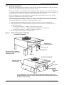
1
Liebert® Challenger™ 3000 with Liebert iCOM®
Operation & Maintenance Manual - 50 & 60Hz
TABLE OF CONTENTS
IMPORTANT SAFETY INSTRUCTIONS . . . . . . . . . . . . . . . . . . . . . . . . . . . . . . . . INSIDE FRONT COVER
SAVE THESE INSTRUCTIONS . . . . . . . . . . . . . . . . . . . . . . . . . . . . . . . . . . . . . . . . . . . . . . . . .1
1.0
INTRODUCTION . . . . . . . . . . . . . . . . . . . . . . . . . . . . . . . . . . . . . . . . . . . . . . . . . . . . . . . . . .4
1.1
System Descriptions . . . . . . . . . . . . . . . . . . . . . . . . . . . . . . . . . . . . . . . . . . . . . . . . . . . . . . . . . . 4
1.1.1
1.1.2
1.1.3
Compressorized Systems . . . . . . . . . . . . . . . . . . . . . . . . . . . . . . . . . . . . . . . . . . . . . . . . . . . . . . . 4
GLYCOOL™ (Chilled Glycol Cooling) Systems. . . . . . . . . . . . . . . . . . . . . . . . . . . . . . . . . . . . . . 4
Chilled Water Systems. . . . . . . . . . . . . . . . . . . . . . . . . . . . . . . . . . . . . . . . . . . . . . . . . . . . . . . . . 4
2.0
STARTUP . . . . . . . . . . . . . . . . . . . . . . . . . . . . . . . . . . . . . . . . . . . . . . . . . . . . . . . . . . . . . .5
2.1
Startup Procedure . . . . . . . . . . . . . . . . . . . . . . . . . . . . . . . . . . . . . . . . . . . . . . . . . . . . . . . . . . . 5
3.0
COMPONENT OPERATION AND MAINTENANCE . . . . . . . . . . . . . . . . . . . . . . . . . . . . . . . . . . .7
3.1
System Testing . . . . . . . . . . . . . . . . . . . . . . . . . . . . . . . . . . . . . . . . . . . . . . . . . . . . . . . . . . . . . . 7
3.1.1
Environmental Control Functions . . . . . . . . . . . . . . . . . . . . . . . . . . . . . . . . . . . . . . . . . . . . . . . . 7
3.2
Filters . . . . . . . . . . . . . . . . . . . . . . . . . . . . . . . . . . . . . . . . . . . . . . . . . . . . . . . . . . . . . . . . . . . . . 9
3.3
Blower Package . . . . . . . . . . . . . . . . . . . . . . . . . . . . . . . . . . . . . . . . . . . . . . . . . . . . . . . . . . . . 10
3.3.1
3.3.2
3.3.3
3.4
Refrigeration System . . . . . . . . . . . . . . . . . . . . . . . . . . . . . . . . . . . . . . . . . . . . . . . . . . . . . . . . 11
3.4.1
3.4.2
3.4.3
3.4.4
3.4.5
3.4.6
3.4.7
3.4.8
3.4.9
3.4.10
3.4.11
3.4.12
3.5
Fan Impellers and Bearings. . . . . . . . . . . . . . . . . . . . . . . . . . . . . . . . . . . . . . . . . . . . . . . . . . . . 10
Belt . . . . . . . . . . . . . . . . . . . . . . . . . . . . . . . . . . . . . . . . . . . . . . . . . . . . . . . . . . . . . . . . . . . . . . . 10
Air Distribution . . . . . . . . . . . . . . . . . . . . . . . . . . . . . . . . . . . . . . . . . . . . . . . . . . . . . . . . . . . . . 10
Suction Pressure. . . . . . . . . . . . . . . . . . . . . . . . . . . . . . . . . . . . . . . . . . . . . . . . . . . . . . . . . . . . .
Discharge Pressure. . . . . . . . . . . . . . . . . . . . . . . . . . . . . . . . . . . . . . . . . . . . . . . . . . . . . . . . . . .
Superheat . . . . . . . . . . . . . . . . . . . . . . . . . . . . . . . . . . . . . . . . . . . . . . . . . . . . . . . . . . . . . . . . . .
Thermostatic Expansion Valve . . . . . . . . . . . . . . . . . . . . . . . . . . . . . . . . . . . . . . . . . . . . . . . . .
Hot Gas Bypass Valve—Not Available on Digital Scroll Units . . . . . . . . . . . . . . . . . . . . . . . .
Air-Cooled Condenser. . . . . . . . . . . . . . . . . . . . . . . . . . . . . . . . . . . . . . . . . . . . . . . . . . . . . . . . .
Charging the Liebert MC™ with Refrigerant—Basic and Premium Efficiency Control . . . .
Water/Glycol-Cooled Condensers. . . . . . . . . . . . . . . . . . . . . . . . . . . . . . . . . . . . . . . . . . . . . . . .
Motorized Ball Valve—Digital Scroll Compressor . . . . . . . . . . . . . . . . . . . . . . . . . . . . . . . . . .
Regulating Valve—Scroll Compressor . . . . . . . . . . . . . . . . . . . . . . . . . . . . . . . . . . . . . . . . . . .
Drycooler Settings . . . . . . . . . . . . . . . . . . . . . . . . . . . . . . . . . . . . . . . . . . . . . . . . . . . . . . . . . . .
Compressor Oil . . . . . . . . . . . . . . . . . . . . . . . . . . . . . . . . . . . . . . . . . . . . . . . . . . . . . . . . . . . . . .
11
11
11
12
12
13
14
18
18
20
22
22
Compressor Replacement. . . . . . . . . . . . . . . . . . . . . . . . . . . . . . . . . . . . . . . . . . . . . . . . . . . . . 23
3.5.1
3.5.2
3.5.3
Compressor Functional Check . . . . . . . . . . . . . . . . . . . . . . . . . . . . . . . . . . . . . . . . . . . . . . . . . . 23
Standard Scroll Compressor Replacement . . . . . . . . . . . . . . . . . . . . . . . . . . . . . . . . . . . . . . . . 24
Digital Scroll Compressor Replacement Procedure . . . . . . . . . . . . . . . . . . . . . . . . . . . . . . . . . 25
3.6
Facility Fluid and Piping Maintenance for Water and Glycol Systems . . . . . . . . . . . . . . . . 25
3.7
Humidifier—Infrared . . . . . . . . . . . . . . . . . . . . . . . . . . . . . . . . . . . . . . . . . . . . . . . . . . . . . . . . 26
3.7.1
3.7.2
3.7.3
Cleaning Humidifier Pan and Float Switch . . . . . . . . . . . . . . . . . . . . . . . . . . . . . . . . . . . . . . . 26
Changing Humidifier Lamps . . . . . . . . . . . . . . . . . . . . . . . . . . . . . . . . . . . . . . . . . . . . . . . . . . . 27
Steam Generating Humidifier . . . . . . . . . . . . . . . . . . . . . . . . . . . . . . . . . . . . . . . . . . . . . . . . . . 28
4.0
TROUBLESHOOTING . . . . . . . . . . . . . . . . . . . . . . . . . . . . . . . . . . . . . . . . . . . . . . . . . . . . . 32
5.0
MAINTENANCE WORKSHEET . . . . . . . . . . . . . . . . . . . . . . . . . . . . . . . . . . . . . . . . . . . . . . . 38
i
FIGURES
Figure 1
Figure 2
Figure 3
Figure 4
Figure 5
Figure 6
Figure 7
Figure 8
Liebert leak detection units . . . . . . . . . . . . . . . . . . . . . . . . . . . . . . . . . . . . . . . . . . . . . . . . . . . . . . . . 8
Recommended liquid sensor locations . . . . . . . . . . . . . . . . . . . . . . . . . . . . . . . . . . . . . . . . . . . . . . . . 8
Outdoor fan/condenser configuration. . . . . . . . . . . . . . . . . . . . . . . . . . . . . . . . . . . . . . . . . . . . . . . . 13
Johnson Controls valve adjustment. . . . . . . . . . . . . . . . . . . . . . . . . . . . . . . . . . . . . . . . . . . . . . . . . 20
Metrex valve adjustment . . . . . . . . . . . . . . . . . . . . . . . . . . . . . . . . . . . . . . . . . . . . . . . . . . . . . . . . . 21
Correct orientation of float switch . . . . . . . . . . . . . . . . . . . . . . . . . . . . . . . . . . . . . . . . . . . . . . . . . . 26
Infrared humidifier lamps . . . . . . . . . . . . . . . . . . . . . . . . . . . . . . . . . . . . . . . . . . . . . . . . . . . . . . . . 27
Steam generating humidifier . . . . . . . . . . . . . . . . . . . . . . . . . . . . . . . . . . . . . . . . . . . . . . . . . . . . . . 28
TABLES
Table 1
Table 2
Table 3
Table 4
Table 5
Table 6
Table 7
Table 8
Table 9
Table 10
Table 11
Table 12
Table 13
Table 14
Table 15
Table 16
Table 17
Table 18
Table 19
Table 20
Zone leak detection kit installation scenarios . . . . . . . . . . . . . . . . . . . . . . . . . . . . . . . . . . . . . . . . . . 9
Recommended free area ft2 (m2) for grilles or perforated panels at output velocities of 550
and 600 fpm (2.8 and 3.1 m/s) . . . . . . . . . . . . . . . . . . . . . . . . . . . . . . . . . . . . . . . . . . . . . . . . . . . . . 10
Discharge pressures . . . . . . . . . . . . . . . . . . . . . . . . . . . . . . . . . . . . . . . . . . . . . . . . . . . . . . . . . . . . . 11
R-407C (R-22) and R-410A refrigerant required, approximate . . . . . . . . . . . . . . . . . . . . . . . . . . . 15
R-407C (R-22) and R-410A interconnecting piping refrigerant charge . . . . . . . . . . . . . . . . . . . . . 15
Target subcooling for ambient outdoor temperature . . . . . . . . . . . . . . . . . . . . . . . . . . . . . . . . . . . 16
Difference in subcooling measurements—Indoor minus outdoor. . . . . . . . . . . . . . . . . . . . . . . . . . 17
Liquid pressure and temperature chart . . . . . . . . . . . . . . . . . . . . . . . . . . . . . . . . . . . . . . . . . . . . . 18
Water/glycol system conditions requiring optional settings for aquastats . . . . . . . . . . . . . . . . . . 22
Aquastat settings—two-fan through four-fan drycoolers . . . . . . . . . . . . . . . . . . . . . . . . . . . . . . . . 22
Compressor oil types . . . . . . . . . . . . . . . . . . . . . . . . . . . . . . . . . . . . . . . . . . . . . . . . . . . . . . . . . . . . . 22
Humidifier canister part numbers . . . . . . . . . . . . . . . . . . . . . . . . . . . . . . . . . . . . . . . . . . . . . . . . . . 30
Blower troubleshooting . . . . . . . . . . . . . . . . . . . . . . . . . . . . . . . . . . . . . . . . . . . . . . . . . . . . . . . . . . . 32
Chilled water troubleshooting . . . . . . . . . . . . . . . . . . . . . . . . . . . . . . . . . . . . . . . . . . . . . . . . . . . . . 32
Compressor and refrigeration system troubleshooting. . . . . . . . . . . . . . . . . . . . . . . . . . . . . . . . . . 33
Dehumidification troubleshooting . . . . . . . . . . . . . . . . . . . . . . . . . . . . . . . . . . . . . . . . . . . . . . . . . . 34
Glycol pump troubleshooting . . . . . . . . . . . . . . . . . . . . . . . . . . . . . . . . . . . . . . . . . . . . . . . . . . . . . . 35
Infrared humidifier troubleshooting . . . . . . . . . . . . . . . . . . . . . . . . . . . . . . . . . . . . . . . . . . . . . . . . 35
Steam generating humidifier troubleshooting . . . . . . . . . . . . . . . . . . . . . . . . . . . . . . . . . . . . . . . . 36
Reheat troubleshooting. . . . . . . . . . . . . . . . . . . . . . . . . . . . . . . . . . . . . . . . . . . . . . . . . . . . . . . . . . . 37
ii
IMPORTANT SAFETY INSTRUCTIONS
SAVE THESE INSTRUCTIONS
This manual contains important safety instructions that should be followed during the installation
and maintenance of the Liebert Challenger 3000 with Liebert iCOM®. Read this manual thoroughly
before attempting to install or operate this unit.
Only qualified personnel should move, install or service this equipment.
Adhere to all warnings, cautions and installation, operating and safety instructions on the unit and in
this manual. Follow all operating and user instructions.
! WARNING
Arc flash and electric shock hazard. Open all local and remote electric power disconnect
switches, verify with a voltmeter that power is off and wear personal protective clothing per
NFPA 70E before working within the electric control enclosure. Failure to comply can cause
injury or death.
Before proceeding with installation, read all instructions, verify that all the parts are included
and check the nameplate to be sure the voltage matches available utility power.
The Liebert iCOM microprocessor does not isolate power from the unit, even in the “Unit Off”
mode. Some internal components require and receive power even during the “Unit Off” mode
of the Liebert iCOM.
The factory-supplied optional disconnect switch is inside the unit. The line side of this switch
contains live high-voltage.
The only way to ensure that there is NO voltage inside the unit is to install and open a remote
disconnect switch. Refer to unit electrical schematic.
Follow all local codes.
! WARNING
Risk of explosive discharge from high-pressure refrigerant. Can cause injury or death.
This unit contains fluids and gases under high pressure. Relieve pressure before working with
piping.
! WARNING
Risk of refrigerant system rupture or explosion from overpressurization. Can cause
equipment damage, injury or death.
Local building or plumbing codes may require that a fusible plug or other type of pressure
relief device be installed in the system.
For systems requiring EU CE compliance (50Hz), the system installer must provide and
install a discharge pressure relief valve rated for a maximum of 500psig (34bar) in the high
side refrigerant circuit. Do not install a shutoff valve between the compressor and the field
installed relief valve. The pressure relief valve must be CE certified to the EU Pressure
Equipment Directive by an EU “Notified Body.”
NOTE
The compressor has a factory-installed high pressure safety switch in the high side refrigerant
circuit. A pressure relief valve is provided with Liebert Lee-Temp™ condensers. Consult your
local building code to determine if the Liebert Fan Speed Control and VFD condensers will
require field-provided pressure-relief devices. A fusible plug kit for Liebert FSC and VFD
condensers is available for field installation.
1
Liebert® Challenger 3000™
! WARNING
Risk of high-speed moving parts. Can cause injury or death.
Open all local and remote electric power disconnect switches, verify with a voltmeter that
power is Off and verify that the blower wheel, pulleys and drive belts have stopped rotating
before working in the unit.
Do not operate upflow units without installing a plenum, ductwork or guard over the blower
opening(s) on the top of the unit cabinet.
Ductwork must be connected to the blower(s), or a plenum must be installed on the blower
deck for protection from rotating blower wheel(s) on upflow units.
! CAUTION
Risk of contact with hot surfaces. Can cause injury.
The compressors, refrigerant discharge lines, humidifiers and reheats are extremely hot
during unit operation. Allow sufficient time for them to cool before working within the unit
cabinet. Use extreme caution and wear protective gloves and arm protection when working on
or near hot compressors, discharge lines, humidifiers and reheats.
NOTICE
Risk of internal system corrosion and frozen coolant fluid. Can cause equipment damage and
major fluid leaks resulting in serious building damage, expensive repair costs and costly
system down time.
Cooling coils, heat exchangers and piping systems that are connected to open cooling towers
or other open water/glycol systems are at high risk of freezing and premature corrosion.
Fluids in these systems must contain the proper antifreeze and inhibitors to prevent freezing
and premature coil, piping and heat exchanger corrosion. The water or water/glycol solution
must be analyzed by a competent local water treatment specialist before startup to establish
the inhibitor and antifreeze solution requirement and at regularly scheduled intervals
throughout the life of the system to determine the pattern of inhibitor depletion.
The complexity of water/glycol solution condition problems and the variations of required
treatment programs make it extremely important to obtain the advice of a competent and
experienced water treatment specialist and follow a regularly scheduled coolant fluid system
maintenance program.
Read and follow individual unit installation instructions for precautions regarding fluid
system design, material selection and use of field-provided devices. Liebert systems contain
iron and copper alloys that require appropriate corrosion protection. It is important to have
the system running with flow through exchangers maintained at initial system fill for 24 to 48
hours depending on size and system configuration.
Water chemistry varies greatly by location, as do the required additives, called inhibitors,
that reduce the corrosive effect of the fluids on the piping systems and components. The
chemistry of the water used must be considered, because water from some sources may
contain corrosive elements that reduce the effectiveness of the inhibited formulation.
Sediment deposits prevent the formation of a protective oxide layer on the inside of the
coolant system components and piping. The water/coolant fluid must be treated and
circulating through the system continuously to prevent the buildup of sediment deposits and
or growth of sulfate reducing bacteria.
Proper inhibitor maintenance must be performed in order to prevent corrosion of the system.
Consult glycol manufacturer for testing and maintenance of inhibitors.
Commercial ethylene glycol, when pure, is generally less corrosive to the common metals of
construction than water itself. It will, however, assume the corrosivity of the water from
which it is prepared and may become increasingly corrosive with use if not properly inhibited.
Liebert® Challenger 3000™
2
NOTICE
Risk of damage from forklift. Can cause unit damage.
Keep tines of the forklift level and at a height suitable to fit below the skid and/or unit to
prevent exterior and/or underside damage.
NOTICE
Risk of improper storage. Can cause unit damage.
Keep the Liebert Challenger 3000 upright, indoors and protected from dampness, freezing
temperatures and contact damage.
NOTICE
Risk of leaking water. Can cause equipment and building damage.
This unit requires a water drain connection. It may also require an external water supply to
operate.
Improper installation, application and service practice can result in water leaking from the
unit. Water leaks can cause severe property damage and loss of critical data center
equipment.
Do not locate unit directly above any equipment that could sustain water damage.
Emerson recommends installing monitored leak detection equipment for unit and supply
lines.
3
Liebert® Challenger 3000™
Introduction
1.0
INTRODUCTION
1.1
System Descriptions
Liebert Challenger 3000 Thermal Management systems are available in several configurations.
1.1.1
Compressorized Systems
NOTE
Compressorized systems may be a self-contained system, with the compressor in the Liebert
Challenger 3000, or a split system, with the compressor in a separate condensing unit.
These systems may be air-cooled, water-cooled or glycol-cooled, depending on the heat rejection
method selected.
Cooling—One stage standard; variable capacity with digital scroll, optional.
Heating—Two stages of electric reheat standard; SCR controlled electric reheat, hot water reheat,
hot gas reheat on water- and glycol-cooled systems optional.
Humidification—Infrared standard; steam generating optional.
Dehumidification—Hot gas bypass locked out standard
1.1.2
GLYCOOL™ (Chilled Glycol Cooling) Systems
GLYCOOL systems have all of the features of a compressorized water or glycol system, plus a second
cooling coil that is connected into the water circuit. When fluid temperature is sufficiently low (below
room temperature), cooling is provided by circulating the fluid through the second cooling coil (flow is
controlled by a motorized valve.) This is then the primary cooling source, and it greatly reduces the
compressor operation.
Cooling—Modulated cooling valve opens proportionally to match room needs (primary), one or two
stages of mechanical refrigeration (secondary)
Heating—Two stages of electric reheat standard; hot water reheat optional
Humidification—Infrared standard; steam generating optional
Dehumidification—Hot gas bypass locked out standard
1.1.3
Chilled Water Systems
These systems utilize a central chiller and control cooling by modulating a control valve in the chilled
water line.
Cooling—Proportional in response to room needs
Heating—Two stages of electric reheat standard; hot water reheat optional
Humidification—Infrared standard; steam generating optional
Dehumidification—Chilled water valve opens proportionally in response to room needs
Liebert® Challenger 3000™
4
Startup
2.0
STARTUP
Before beginning startup, make certain that unit was installed according to the instructions in the
installation manual, SL-11962. Verify that the fan shipping bolt has been removed, the check valve
has been installed (on air-cooled units), and that the scroll compressor is rotating in the proper
direction. All exterior panels must be in place with the front panel open.
Locate the startup form supplied with your unit documents. Complete the form during startup and
mail it to Liebert when startup is completed. Contact your Liebert supplier if you have any questions
or problems during unit installation, startup or operation.
! WARNING
Arc flash and electric shock hazard. Open all local and remote electric power disconnect
switches, verify with a voltmeter that power is off and wear personal protective clothing per
NFPA 70E before working within the electric control enclosure. Failure to comply can cause
injury or death.
Potentially lethal voltages exist within this equipment during operation. Observe all cautions
and warnings on unit and in this manual.
The Liebert iCOM does not isolate power from the unit, even in the “Unit Off” mode. The only
way to ensure that there is NO voltage inside the unit is to install and open a remote
disconnect switch. Refer to unit electrical schematic.
2.1
Startup Procedure
1. Disconnect all power to the environmental control unit.
2. Tighten all electrical wiring connections that may have loosened during shipping (on electric
panel and at all major components, such as compressor, reheats, humidifier and motor).Retighten
according to values listed on component by component manufacturer.
3. Remove all line voltage fuses except the main fan fuses at the far right of the electric panel and
the Control Voltage fuses at the far left of the electric panel. For units supplied with circuit
breakers, open the circuit breakers instead of removing fuses.
4. Turn on power and check line voltage on main unit disconnect switch. Line voltage must be
within 10% of nameplate voltage.
5. Turn On main unit disconnect switch and check secondary voltage at transformer T1. Voltage at
T1 must be 24 VAC ±2.5 VAC (check at TB1-1 and TB1-8). If tolerance is exceeded, change the
transformer primary tap.
6. Push the On button. Blower will start.
7. If you do not want your unit to operate at factory default settings, set temperature and humidity
setpoints, alarms and other control functions. Refer to the iCOM User Manual SL-18835.
8. Stop the unit by depressing the On/Off button on the front display. Turn Off main unit disconnect
and main breaker.
9. Replace all fuses (or reset circuit breakers) that were removed in Step 3.
10. Restore power to unit; turn On the main unit disconnect switch.
11. Push the On button—putting the unit into operation.
12. Check the current draw on all line voltage components and match with serial tag.
13. Verify that the scroll compressor is rotating in the proper direction.
NOTICE
Risk of improper wiring/phase sequencing. Can cause backward compressor rotation, poor
performance and compressor damage.
Three-phase power must be connected to the unit line voltage terminals in the proper
sequence so that the scroll compressor rotates in the proper direction. Rotation in the wrong
direction will result in poor performance and compressor damage. Use a phase sequence and
motor rotation sensor to ensure that the three-phase power is correctly connected and that the
compressor is rotating properly.
5
Liebert® Challenger 3000™
Startup
14.
15.
16.
17.
18.
Check for unusual noises and vibration.
Check all refrigerant and fluid lines for leaks.
Test all functions of your unit for proper operation.
Close high voltage dead front cover and latch.
Close front accent panel and latch.
Return completed startup form to:
Liebert Corporation
Warranty Registration
1050 Dearborn Drive
P.O. Box 29186
Columbus, OH 43229
Liebert® Challenger 3000™
6
Component Operation and Maintenance
3.0
COMPONENT OPERATION AND MAINTENANCE
3.1
System Testing
3.1.1
Environmental Control Functions
The performance of all control circuits can be tested by actuating each of the main functions. This is
done by temporarily changing the setpoints.
Cooling
To test the cooling function, set the setpoint for a temperature of 10°F (5°C) below room temperature.
A call for cooling should be seen and the equipment should begin to cool. A high temperature alarm
may come On. Disregard it. Return setpoint to the desired temperature.
Heating
Reheat may be tested by setting the setpoint for 10°F (5°C) above room temperature. A call for
heating should be seen and the heating coils should begin to heat. Disregard the temperature alarm
and return the setpoint to the desired temperature.
Humidification
To check humidification, set the humidity setpoint for an RH 10% above the room humidity reading.
For infrared humidifiers, the infrared element should come On. Steam generating humidifiers should
click immediately as it energizes. After a short delay, the canister will fill with water. The water will
heat and steam will be produced. Return the humidity setpoint to the desired humidity.
Dehumidification
Dehumidification can be checked by setting the humidity setpoint for an RH 10% below room relative
humidity. The compressor should come On. Return humidity setpoint to the desired humidity.
Electric Panel
The electric panel should be inspected for any loose electrical connections.
! WARNING
Arc flash and electric shock hazard. Open all local and remote electric power supply
disconnect switches, verify with a voltmeter that power is Off and wear personal protective
clothing over NFPA 70E before working within the electric control enclosure. Failure to
comply can cause injury or death.
The Liebert iCOM does not isolate power from the unit, even in the “Unit Off” mode. Some
internal components require and receive power even during the “Unit Off” mode of the Liebert
iCOM.
The only way to ensure that there is NO voltage inside the unit is to install and open a remote
disconnect switch. Refer to the unit’s electrical schematic.
Verify that all power has been disconnected from the unit before attempting to tighten any
fittings or connections.
Control Transformer and Fuses
The control system is divided into four separate circuits. The control voltage circuits are individually
protected by fuses located on the transformer/fuse board. If any of the fuses are blown, first eliminate
shorts, then use spare fuses supplied with unit. Use only type and size of fuse specified for your unit.
The small isolation transformer on the board supplies 24 volts to the main control board. The
transformer is internally protected. If the internal protector opens, the transformer/fuse board must
be replaced. Also check the control voltage fuse on the main control board before replacing the
transformer/fuse board.
Fan Safety Switch
The fan safety switch is in the electric compartment and consists of a diaphragm switch and
interconnecting tubing to the blower scroll. The fan safety switch is wired directly to the control
circuit to activate the alarm system if the airflow is interrupted
7
Liebert® Challenger 3000™
Component Operation and Maintenance
High-Temp Sensor
The optional high-temp sensor is a bimetal-operated sensing device with a normally closed switch.
This device will shut down the entire unit when the inlet air temperature exceeds a preset point. It is
connected between Terminals 1 and 2 at Plug P39.
Smoke Detector
The optional smoke detector power supply is located on the base of the upflow units, and at the top of
downflow units. It is constantly sampling return air through a tube. No adjustments are required.
Water Detection Sensor
! WARNING
Risk of fire or explosion. Can cause injury or death.
Do not use near flammable liquids or for flammable liquid detection.
The optional water detection devices available are a point leak detection sensor and a zone leak
detection kit. Emerson recommends remote monitoring of these devices for timely detection of water
leaks that can cause expensive building and equipment damage if not resolved immediately.
Figure 1
Liebert leak detection units
Liebert Liqui-tect® Point
Leak Detection Sensor
LT460 Zone Leak Detection Kit
The point leak detection sensor provides leak detection at a critical point. A simple two-wire
connection signals the alarms at a Liebert Thermal Management unit or at a monitoring panel. Run
wires to the Liebert unit and connect them to terminals 24 and 51, 55 or 56. Use NEC Class 2, 24V
wiring. The sensor contains a solid state switch that closes when water is detected by the twin sensor
probes. The sensor is hermetically sealed in all thread PVC nipple and is to be mounted where water
problems may occur. The sensor should be located 6-8 feet (2-2.5m) from the environmental control
unit in a wet trap or near a floor drain. It should not be mounted directly under the unit.
Figure 2
Recommended liquid sensor locations
Liebert
Unit
Recommended
Liebert Liqui-tect point
leak locations
Floor drain
Liebert® Challenger 3000™
8
Component Operation and Maintenance
The zone leak detection kit provides leak detection for a defined zone. This kit is ideal for perimeter
sensing or serpentine coverage of small areas. A simple, two-wire connection signals the alarms at a
Liebert Thermal Management unit or at a monitoring panel. Run wires to the Liebert unit and
connect them to terminals 24 and 51, 55 or 56. The sensor utilizes Liebert's LT500Y leak detection
cable. The kit is offered with five different lengths of cable sized specifically for the type of Liebert
Thermal Management unit (see matrix below). Refer to matrix below for the recommended location of
leak detection cable.
Table 1
Zone leak detection kit installation scenarios
Scenarios
Upflow Unit
Detection
around
entire unit
Upflow Unit
Detection on sides
and
in front of unit
2-ft clearance
in front
2-ft clearance
in front
Downflow Unit
Detection
around
entire unit
Downflow Unit
Detection on sides
and
in front of unit
6-ft clearance
in front
6-ft clearance
in front
Distance From Unit, feet (m)
In back
2 (0.6)
No cable behind
1 (0.3)
No cable behind
On sides
2 (0.6)
2 (0.6)
1 (0.3)
1 (0.3)
In front
2 (0.6)
2 (0.6)
6 (1.8)
6 (1.8)
Unit (footprint-in.)
Liebert Challenger 3000
(32.5 x 32.5)
Part Number
LT460-Z30
LT460-Z20
LT460-Z30
LT460-Z25
Remote Shutdown
A connection point is provided for customer supplied remote shutdown devices. This terminal strip is
located at the top of upflow units, and at the base of downflow units. Terminals 37 and 38 on the
terminal strip are jumpered when no remote shutdown device is installed.
3.2
Filters
Filters are usually the most neglected item in an environmental control system. To maintain efficient
operation, they should be checked monthly and changed as required. Because replacement intervals
vary with environmental condition and filter type, each unit is equipped with a filter clog switch. This
warns of restricted airflow through the filter compartment by activating the Change Filter alarm.
Turn power Off before replacing filters.
Liebert Challenger 3000 filters are 28-1/2" by 29-1/2", either 2" or 4" thick, plus an optional 2" thick
pre-filter. The filter is replaced from the front of the unit. On upflow units, the filter is vertical, in
front of the lower compartment. Pull the filter out toward you to remove it. On downflow units, the
filter is horizontal, above the electrical panel. Slide the filter out toward you to remove it.
After replacing the filter(s), test the operation of the filter clog switch. Turn the adjusting screw
counter clockwise to trip the switch — this will energize the Change Filter alarm. To adjust the
switch proceed as follows: With the fan running, set the switch to energize the light with clean filters.
The unit panels must all be in place and closed to accurately find this point. Then turn the adjusting
knob one turn clockwise, or to the desired filter change point.
9
Liebert® Challenger 3000™
Component Operation and Maintenance
3.3
Blower Package
Periodic checks of the blower package include: belt, motor mounts, fan bearings, and impellers.
3.3.1
Fan Impellers and Bearings
Fan impellers should be periodically inspected and any debris removed. Check to see if they are
tightly mounted on the fan shaft. Rotate the impellers and make sure they do not rub against the fan
housing.
Bearings used on the units are permanently sealed and self-lubricating. They should be inspected for
signs of wear when the belt is adjusted. Shake the pulley and look for movement in the fan shaft. If
any excessive movement is noticed, bearings should be replaced. However, the cause of the wear must
be determined and corrected before returning the unit to operation.
3.3.2
Belt
The drive belt should be checked monthly for signs of wear and proper tension. Pressing in on belts
midway between the sheave and pulley should produce from 1/2" to 1" (12 to 25 mm) of movement.
Belts that are too tight can cause excessive bearing wear.
Belt tension can be adjusted by raising or lowering the fan motor base. Loosen nut above motor
mounting plate to remove belt. Turn nut below motor mounting plate to adjust belt tension. If belt
appears cracked or worn, it should be replaced with a matched belt (identically sized). With proper
care, a belt should last several years.
NOTICE
Risk of improper adjustment. Can cause equipment damage.
After adjusting or changing the belt, check to ensure that the motor base nuts are tightened.
The bottom adjustment nut should be finger tight. The top locking nut should be tightened
with a wrench. The motor sheave must be parallel to and aligned with the blower wheel
pulley to maximize belt life.
3.3.3
Air Distribution
All unit models are designed for constant volume air delivery. Therefore any unusual restrictions
within the air circuit must be avoided. For downflow models operating on a raised floor, refer to
Table 2 for recommended free area for proper air flow.
Recommended free area ft2 (m2) for grilles or perforated panels at output velocities of
550 and 600 fpm (2.8 and 3.1 m/s)
Table 2
550 FPM
(2.8 m/s)
600 FPM
(3.1 m/s)
3 Ton
3.3 (0.31)
3.0 (0.28)
5 Ton
5.1 (0.41)
4.7 (0.44)
3 Ton
3.3 (0.31)
3.0 (0.28)
5 Ton
4.7 (0.44)
4.3 (0.40)
Model
60 Hz Units
50 Hz Units
Grilles used in raised floors vary in size, the largest being 18" x 6" (46 cm x 15 cm). This type of grille
has approximately 56 in2 (361 cm2) of free area. Perforated Panels are usually 2' x 2' (61 cm x 61 cm)
and have a nominal free area of approximately 108 to 144 in2 (697 to 929 cm2).
NOTICE
Risk of airflow restriction. Can cause inefficient operation and equipment overheating.
In raised-floor use, all under-floor restrictions, such as clusters of cables or piping, must be
avoided because they may form barriers to airflow. Whenever possible, cables and pipes
should be run parallel to the airflow. Never stack cables or piping.
Liebert® Challenger 3000™
10
Component Operation and Maintenance
3.4
Refrigeration System
Each month, the components of the refrigeration system should be inspected for proper function and
signs of wear. Since, in most cases, evidence of malfunction is present prior to component failure,
periodic inspections can be a major factor in the prevention of most system failures.
Refrigerant lines must be properly supported and not allowed to vibrate against ceilings, floors or the
unit frame. Inspect all refrigerant lines every six months for signs of wear and proper support. Also
inspect capillary and equalizer lines from the expansion valve and support as necessary.
Each liquid line has a sight glass that indicates liquid refrigerant flow and the presence of moisture.
Bubbles in the sight glass do not indicate a shortage of refrigerant or a restriction in the liquid line.
The moisture indicator changes from green to yellow when moisture is present in the system.
3.4.1
Suction Pressure
Suction pressure will vary with load conditions. The low pressure transducer will shut the compressor
down if suction pressure falls below the cut-out setting. High suction pressure reduces the ability of
the refrigerant to cool compressor components and can result in compressor damage.
NOTE
Liebert Challenger 3000 fan coil units do not monitor suction pressure using a transducer. On
these models, low-pressure management is accomplished using freeze stats located on the
evaporator coil. See the Liebert iCOM® user manual, SL-18835, for more information.
Additional low-pressure management routines may apply during compressor start and normal
operation. See the Liebert iCOM user manual, SL-18835, for more information. The document is
available on Liebert’s Web site: www.liebert.com
3.4.2
Discharge Pressure
Discharge Pressure can be increased or decreased by load conditions or condenser efficiency. The high
pressure switch will shut the compressor down at its cut-out setting. Refer to Table 3, below.
Table 3
Discharge pressures
System Design
Discharge Pressure
PSIG (kPa)
Air-Cooled
295 (2035)
65-75°F (18-24°C) fluid
Water/Glycol-Cooled
3.4.3
239 (1650)
85°F (29°C) fluid
255 (1760)
115°F (46°C) fluid
335 (2310)
Maximum
365 (2516)
High Pressure Cut-Out
400 (2760)
Superheat
Superheat can be adjusted by the Thermostatic Expansion Value (TEV). To determine superheat:
1.
2.
3.
4.
5.
Measure the temperature of the suction line at the point the TEV bulb is clamped.
Obtain the gauge pressure at the compressor suction valve.
Add the estimated pressure drop between bulb location and suction valve.
Convert the sum of the two pressures to the equivalent temperature.
Subtract this temperature from the actual suction line temperature. The difference is superheat.
11
Liebert® Challenger 3000™
Component Operation and Maintenance
3.4.4
Thermostatic Expansion Valve
Operation
The thermostatic expansion valve performs one function. It keeps the evaporator supplied with
enough refrigerant to satisfy load conditions. It does not effect compressor operation.
Proper valve operation can be determined by measuring superheat. If too little refrigerant is being fed
to the evaporator, the superheat will be high; if too much refrigerant is being supplied, the superheat
will be low. The correct superheat setting is between 10 and 15°F (5.6 and 8.3°C).
Adjustment
To adjust the superheat setting:
1. Remove the valve cap at the bottom of the valve.
2. Turn the adjusting stem counterclockwise to lower the superheat.
3. Turn the adjusting stem clockwise to increase the superheat.
NOTE
Make no more than one turn of the stem at a time. As long as 30 minutes may be required
for the new balance to take place.
3.4.5
Hot Gas Bypass Valve—Not Available on Digital Scroll Units
Operation—Self-Contained Units
The hot gas bypass is inserted between the compressor discharge line and the leaving side of the
expansion valve through the side outlet distributor. The system, with normal operation when the
evaporator is under full load, will maintain enough pressure on the leaving side of the hot gas valve to
keep the valve port closed.
If the load on the evaporator decreases, the evaporator will get colder. When the coil is too cold, the
internal pressure in the evaporator drops and allows the hot gas bypass valve to open. Hot gas then
mixes with the liquid coolant on the discharge side of the expansion valve raising the temperature
and pressure in the evaporator. The net result is a reduction in the cooling capacity of the unit to
match the load.
To aid in lubricating the compressor, the hot gas bypass solenoid is delayed for 30 seconds on the
initial call for cooling and de-energized for 30 seconds during every 60 minutes of continuous
operation.
NOTE
These procedures are not applicable to condensing units. For condensing unit information,
refer to Liebert’s condensing unit manual, SL-10059, available at the Liebert Web site,
www.liebert.com
Adjustment
Upon deciding what evaporator temperature is desired, the following procedure should be used to
adjust the hot gas bypass valve:
1.
2.
3.
4.
5.
6.
7.
8.
Install the suction and discharge pressure gauge.
Adjust the temperature setpoint to call for cooling so that the refrigeration compressor will run.
Remove the TOP adjusting nut from the valve.
Insert an Allen wrench in the brass hole at top of the valve in adjusting port, and turn
CLOCKWISE if a higher evaporator temperature is required.
After obtaining the suction pressure required, reinstall the cap tightly making sure there are no
leaks.
Let the evaporator operate for approximately 10 to 15 minutes to make sure the suction pressure
is within the desired range.
There will be a fluctuation of approximately 3 to 6 PSIG (21 to 41 kPa) on the evaporator due to
the differential on the hot gas bypass.
Return the temperature setpoint to desired number.
Liebert® Challenger 3000™
12
Component Operation and Maintenance
3.4.6
Air-Cooled Condenser
Restricted airflow through the condenser coil will reduce the operating efficiency of the unit and can
result in high compressor head pressure and loss of cooling.
Clean the condenser coil of all debris that will inhibit air flow. This can be done with compressed air
or commercial coil cleaner. Check for bent or damaged coil fins and repair as necessary. In winter, do
not permit snow to accumulate around the sides or underneath the condenser.
Check all refrigerant lines and capillaries for vibration isolation. Support as necessary. Visually
inspect all refrigerant lines for signs of oil leaks.
Checking Refrigerant Charge (Liebert Lee–Temp ™/Flood Back Head Pressure Control)
The system refrigerant level must be checked periodically. To do so:
1. Adjust temperature setpoint in the unit so that the compressor will run continuously.
2. The refrigerant level is visible through two sight glasses on the receiver and will vary with
ambient temperature.
a. 40°F (4.4°C) and lower — Midway on the bottom sight glass.
b. 40 to 60°F (4.4 to 15.6°C) — Bottom sight glass should be clear with liquid.
c. 60°F (15.6°C) and above — Midway on the top sight glass.
3. Return temperature setpoint to desired number.
Figure 3
Outdoor fan/condenser configuration
FAN SPEED CONDENSER
Electric service
supplied by others
*B
Hot gas line
Secure each leg to condenser
frame at all points shown using
hardware provided.
Liquid line
LEE-TEMP CONDENSER
Lee-Temp heater pad
connection box
*B
Hot gas line
Liquid line
Electric
service
supplied by
others
*B - Inverted traps are to be field-supplied and installed (typical). When installing traps,
provide clearance for swing end of access door. Traps are to extend above base of coil by a
minimum of 7-1/2" (190 mm).
13
Liebert® Challenger 3000™
Component Operation and Maintenance
3.4.7
Charging the Liebert MC™ with Refrigerant—Basic and Premium Efficiency Control
Liebert MC condensers are charge-sensitive and require accurate calculation of the system charge to
avoid overcharging. To avoid overcharge, additional guidelines are recommended to ensure trouble
free operation.
• When charging a system when the outdoor temperature is below 50°F (10°C), recheck the
subcooling against Table 6 when the ambient is above 60°F (15.6°C).
• The indoor space should be maintained between 70°F and 80°F (21-26.7°C) return air before final
charge adjustments are made.
• Charging a unit when return air temperatures are above 80°F (26.7°C) may result in the unit
being overcharged.
• Charge by subcooling measurement at the indoor unit. See Table 6 for target subcooling
temperatures.
• Pressure and temperature measuring instruments should be capable of measuring to ±10 psig
(68.9kPa) and ± 2°F (1.1°C) for best subcooling measurement.
1. Check indoor nameplate for refrigerant type to be used. Unit control configurations differ
depending on refrigerant type.
2. Completing the refrigerant charging requires operating the system for the latter steps. Refer to
the Checklist for Completed Installation in the Liebert Challenger 3000 installation manual,
SL-11962.
3. Calculate the amount of charge for the system. Refer to the Liebert Challenger 3000 installation
manual, SL-11962, and to the condenser and refrigerant line charge data in Tables 4 and 5 in
this document.
4. Accurately weigh in as much of the required system charge as possible before starting the unit.
Do not exceed the calculated charge by more than 0.5 lb (.23kg).
NOTICE
Risk of improper refrigerant charging. Can cause equipment damage.
Refrigerant R-407C and R-410A are blended refrigerants and must be introduced and charged
from the cylinder only as a liquid.
When adding liquid refrigerant to an operating system, it may be necessary to add the
refrigerant through the compressor suction service valve. Care must be exercised to avoid
damage to the compressor. Emerson recommends connecting a sight glass between the
charging hose and the compressor suction service valve. This will permit adjustment of the
cylinder hand valve so that liquid can leave the cylinder while allowing vapor to enter the
compressor.
NOTICE
Risk of refrigerant overcharge, Can cause equipment damage.
Do not use the sight glass as an indicator when charging Liebert MC systems.
5. Turn On the Liebert MC disconnect switch.
6. Turn On the Liebert Challenger 3000 disconnect switch
7. Operate the system for 30 minutes, using the charging function of the Liebert Challenger 3000
control for each circuit of the system.
The charging function is in the diagnostic section of the Liebert iCOM® control (see the Liebert
iCOM user manual, SL-18835). The charging function operates the compressor(s) at full capacity
and energizes the liquid line solenoid valve(s). The reheat and humidifier are disabled. Manual
operation of the indoor fans from the diagnostic menu of the Liebert iCOM is required. A
minimum 20psig (138kPa) must be established and maintained for the compressor to operate.
The charging function can be reset as many times as required to complete unit charging.
Liebert® Challenger 3000™
14
Component Operation and Maintenance
R-407C (R-22) and R-410A interconnecting piping refrigerant charge
Table 4
R-407C (R-22),
lb/100 ft. (kg/30m)
R-410A, lb/100 ft. (kg/30m)
Line Size
O.D., in.
Hot Gas Line
Liquid Line
Hot Gas Line
Liquid Line
3/8
—
3.6 (1.6)
—
3.2 (1.5)
1/2
0.5 (0.2)
6.7 (3.1)
0.7 (0.3)
5.9 (2.7)
5/8
0.8 (0.4)
10.8 (4.9)
1.1 (0.5)
9.6 (4.4)
3/4
1.2 (0.6)
16.1 (7.3)
1.6 (0.7)
14.3 (6.5)
7/8
1.7 (0.8)
22.3 (10.2)
2.3 (1.0)
19.8 (9.1)
1-1/8
2.9 (1.3)
38.0 (17.4)
3.9 (1.8)
33.8 (15.5)
1-3/8
4.4 (2.0)
57.9(26.5)
5.9 (2.7)
51.5 (23.5)
1-5/8
6.2 (2.8)
—
8.4 (3.8)
—
Data based on 50°F (10°C) superheat, 125°F (52°C) SCT, 10°F (-12°C) subcooling.
Table 5
R-407C (R-22) and R-410A refrigerant required, approximate
Condenser
models
Dual Circuit
lb/circuit (kg/circuit)
Single Circuit lb (kg)
Approximate R-407C (R-22) Refrigerant Needed
MCS 028
2.2 (1.0)
N/A
MCM 040
3.0 (1.4)
N/A
MCM 080
7.5 (3.4)
3.0 (1.4)
MCL 055
5.0 (2.3)
N/A
MCL 110
10.5 (4.8)
5.1 (2.3)
MCM160
NA
7.5(3.4)
MCL 165
18.3 (8.3)
N/A
MCL 220
27.0 (12.3)
12.2 (5.6)
Approximate R-410A Refrigerant Needed
MCS 028
2.5 (1.2)
N/A
MCM 040
3.5 (1.6)
N/A
MCM 080
8.5 (3.8)
3.5 (1.6)
MCL 055
5.0 (2.3)
N/A
MCL 110
10.7 (4.9)
5.2 (2.4)
MCM160
NA
8.5(3.8)
MCL 165
18.4 (8.4)
N/A
MCL 220
27.0 (12.3)
12.3 (5.6)
8. Attach pressure and temperature instruments to the liquid line of the indoor unit. Measure the
initial subcooling and continue to add charge until the recommended subcooling for the current
outdoor ambient temperature is reached (see Table 6. The outdoor ambient can be read from the
Liebert MC™ condenser control menu ID F02
NOTE
To determine the subcooling measurement, a liquid line pressure reading (at the factory
installed Schrader tap) needs to be measured along with obtaining a temperature reading on
the liquid line. Convert the liquid line pressure reading into a temperature by utilizing a
pressure-temperature guide. The difference between this converted temperature and the actual
temperature will determine the system’s subcooling. For R-407C, make sure to use the
saturated liquid temperature to calculate subcooling.
15
Liebert® Challenger 3000™
Component Operation and Maintenance
Table 6
Target subcooling for ambient outdoor temperature
Ambient Temp
°F (C°)
Subcooling
°F (C°)
Ambient Temp
°F (C°)
Subcooling
°F (C°)
0 (-17.8)
22 (12.0)
80 (26.7)
13 (7.2)
10 (-12.2)
22 (12.0)
90 (32.2)
9 (5.0)
20 (-6.7)
22 (12.0)
95 (35.0)
7 (3.9)
30 (-1.1)
22 (12.0)
100 (37.8)
5 (2.9)
40 (4.4)
22 (12.0)
105 (40.6)
3 (1.8)
50 (10.0)
21 (11.7)
110 (43.3)
1 (0.7)
60 (15.6)
19 (10.8)
125 (51.7)
00
70 (21.1)
17 (9.3)
9. Verify the subcooling calculated from measured values at the evaporator against the subcooling
reading of the Liebert MC™ control [menu ID F50 & F51]. If the subcooling calculated with gauges
differs from the Liebert MC subcooling by more than 3°F (1.7°C), then adjust the charge amount
to achieve the target subcooling per Table 6 based the Liebert MC control subcooling.
Failure to check measured subcooling with refrigerant gauges against the Liebert MC subcooling
may result in an overcharged system. See NOTE below and Table 7 for correction to Liebert MC
subcooling that may be required based on condenser elevation above the indoor evaporator.
NOTE
If the condenser is part of an R-22 system, the configuration of the condenser must be changed
to read the subcooling correctly. The value of menu ID C09 of the Liebert MC control must be
changed to “1”.
NOTE
The evaporator subcooling will be greater than the condenser subcooling when the Liebert MC
is mounted higher than the indoor evaporator. Subcooling adjustment is needed when the
Liebert MC is located greater than 40 ft above evaporator.
Sample Calculations
The Liebert MC is 40 ft. above the evaporator of an R-407C system. The outdoor ambient from the
Liebert MC condenser control menu ID F02, is 94.8°F. The liquid pressure is 300 psig and the liquid
temperature is 113°F. The subcooling from the Liebert MC control is 5°F. Determine the subcooling
and verify the calculated subcooling against the reading of the Liebert MC control [menu ID F50 &
F51].
Evaporator Subcooling Calculation
a.
b.
c.
d.
e.
f.
g.
Refrigerant Type: R-407C
Ambient Temperature: 94.8°F
Condenser Elevation: 40 ft.
Condenser Elevation Temperature Correction: 4°F
Liquid Line Pressure: 300
Liquid Pressure converted to Saturated Liquid Temperature: 120.3°F
Measured Liquid Line Temperature: 113.2°F
MC Condenser Subcooling Reading: 5°F
(Menu ID F50 for Circuit #1 or Menu ID F51 for Circuit #2)
Subtract Line f (Measured Line Temperature) from Line e. (Liquid Pressure converted to
Temperature) to obtain Calculated Subcooling.
Line e:
Line f:
h. Calculated Subcooling:
Liebert® Challenger 3000™
120.3°F
-113.2°F
7.1°F or 7°F
16
Component Operation and Maintenance
Elevation Correction
Subtract Line c. (Correction for Condenser Elevation above Evaporator) from Line h. (Calculated
Subcooling) to obtain Corrected Subcooling.
i.
Line h:
7°F
Line c:
-4°F
Corrected Subcooling 3°F
Verification Against MC Condenser
Subtract Line g. (MC Condenser Subcooling Reading) from Line i. (Corrected Subcooling) to obtain
Difference.
Line i:
3°F
Line g:
-5°F
j. Difference
-2°F
• If Line j (Difference value) is less than ±3°F, NO charge adjustment is needed.
• If Line j (Difference value) is less than -3°F, add additional charge.
• If Line j (Difference value) is greater than +3°F, the system is overcharged and charge must
be removed.
Table 7
Difference in subcooling measurements—Indoor minus outdoor
Liebert MC™ elevation above
evaporator, ft. (m)
Refrigerant Type
Elevation subcooling correction - °F(°C)
80 (24)
60 (18)
40 (12)
20 (6)
R-22
12 (6.6)
9 (5.0)
5 (2.8)
1 (0.6)
R-407C
10 (5.5)
7 (3.8)
4 (2.2)
1 (0.6)
R-410A
6 (3.3)
4 (2.2)
2 (1.1)
0 (0.0)
10. As head pressure builds, the variable fan speed controlled condenser fan begins rotating. The fan
will run at full speed when sufficient head pressure is developed.
17
Liebert® Challenger 3000™
Component Operation and Maintenance
Table 8
Liquid pressure and temperature chart
Pressure
R407C *
R410A *
R22
Psig (Bar)
°F (°C)
°F (°C)
°F (°C)
170 (11.7)
81.5 (27.5)
59.8 (15.4)
90.6 (32.6)
180 (12.4)
85.1 (29.5)
63.1 (17.3)
94.3 (34.6)
190 (13.1)
88.6 (31.5)
66.3 (19.1)
97.9 (36.6)
200 (13.8)
92.0 (33.3)
69.5 (20.8)
101.4 (38.6)
210 (14.5)
95.2 (35.1)
72.5 (22.5)
104.7 (40.4)
220 (15.2)
98.3 (36.8)
75.4 (24.1)
108.0 (42.2)
230 (15.9)
101.4 (38.5)
78.2 (25.7)
111.1 (44.0)
240 (16.6)
104.3 (40.2)
80.9 (27.2)
114.2 (45.7)
250 (17.2)
107.2 (41.8)
83.6 (28.7)
117.1 (47.3)
260 (17.9)
109.9 (43.3)
86.2 (30.1)
120.0 (48.9)
270 (18.6)
112.6 (44.8)
88.7 (31.5)
122.8 (50.4)
280 (19.3)
115.3 (46.3)
91.1 (32.8)
125.5 (52.0)
290 (20.0)
117.8 (47.7)
93.5 (34.2)
128.2 (53.4)
300 (20.7)
120.3 (49.1)
95.8 (35.5)
130.8 (54.9)
310 (21.4)
122.8 (50.4)
98.1 (36.7)
133.3 (56.3)
320 (22.1)
125.2 (51.8)
100.3 (38.0)
135.8 (57.7)
330 (22.8)
127.5 (53.1)
102.5 (39.2)
138.2 (59.0)
340 (23.4)
129.8 (54.3)
104.6 (40.3)
140.6 (60.3)
350 (24.1)
132.1 (55.6)
106.7 (41.5)
142.9 (61.6)
360 (24.8)
134.3 (56.8)
108.7 (42.6)
145.2 (62.9)
370 (25.5)
136.4 (58.0)
110.7 (43.7)
147.4 (64.1)
380 (26.2)
138.6 (59.2)
112.7 (44.8)
149.6 (65.4)
390 (26.9)
140.6 (60.3)
114.5 (45.9)
151.8 (66.5)
400 (27.6)
142.7 (61.5)
116.4 (46.9)
153.9 (67.7)
500 (34.5)
161.3 (71.8)
133.5 (56.4)
173.1 (78.4)
600 (41.4)
177.4 (80.8)
148.1 (64.5)
189.5 (87.5)
* Values are for saturated liquid
3.4.8
Water/Glycol-Cooled Condensers
Coaxial Condenser
Each water- or glycol-cooled module has a coaxial condenser that consists of a steel outside tube and a
copper inside tube.
Coaxial condensers do not normally require maintenance or replacement if the water supply is clean.
If your system operates at high head pressure with reduced capacity, and all other causes have been
eliminated, the coaxial condenser may be obstructed and needs to be replaced.
3.4.9
Motorized Ball Valve—Digital Scroll Compressor
On water-cooled and glycol-cooled digital scroll units, the discharge pressure is controlled by a
motorized ball valve. During unloaded operation, the pressure changes during each digital cycle could
result in excessive repositions with a pressure operated water regulating valve. The control algorithm
for the motorized ball valve uses an intelligent sampling rate and adjustable pressure thresholds to
reduce valve repositions. The valve assembly consists of the brass valve, linkage and actuator.
Liebert® Challenger 3000™
18
Component Operation and Maintenance
Control
The valve actuator operates on 24VAC power and is controlled by a 2-10VDC proportional control
signal. The valve full open to full close time is 60 seconds. At 2VDC the valve is closed; at 10VDC the
valve is fully open. There is a 20-second delay to position the motorized ball valve before starting the
compressor.
Control Method
The control utilizes an upper and lower pressure threshold with a 35 PSI (241 kPa) deadband to
reduce valve movement. If the liquid pressure is between the upper and lower threshold the valve
remains at the current position. If the liquid pressure exceeds the upper threshold the valve opens,
and if the pressure falls below the lower threshold the valve closes. There are multiple adjustment bands to
ease discharge pressure back into control range.
Adjustment
Both pressure thresholds can be shifted simultaneously over a 50 PSI (345 kPa) range (the 35 PSI
[241 kPa] differential remains constant). The ball valve setpoint offset parameter in the Service menu
can be adjusted from 0 to 50 PSI (345 kPa) to raise or lower the control band similar to the pressure
adjustment on a water regulating valve. Units are factory set at a 30 PSI (207 kPa) setpoint offset (30
PSI [207 kPa] above minimum). This results in a 220 PSIA (1517 kPa) lower threshold and a 255
PSIA (1758 kPa) upper threshold pressure.
Startup
The setpoint offset is adjusted to the minimum value during startup, then transitions to the set value
once the compressor reaches normal operating pressures. Additionally changes in fluid temperature
could cause pressure changes that do not result in valve movement within the dead band on
drycoolers. Fan cycling stats should be set to prevent continuous fluid temperature swings greater
than 10oF (5.6oC) (see 3.4.11 - Drycooler Settings).
Location
The motorized ball valves are located in the condenser fluid return line. The three-way valve is piped
in a mixing arrangement with the common port at the valve outlet.
Manual Control
The valve can be manually set by disconnecting AC power, depressing the manual override button on
the valve actuator, and adjusting the valve position with the handle. You also have the option to
control the motorized ball valves through the Service menu using manual mode to override the
normal control.
19
Liebert® Challenger 3000™
Component Operation and Maintenance
3.4.10 Regulating Valve—Scroll Compressor
The water regulating valve automatically regulates the amount of fluid necessary to remove the heat
from the refrigeration system, permitting more fluid to flow when load conditions are high and less
fluid to flow when load conditions are low. The valve consists of a brass body, balance spring, valve
seat, valve disc holders, capillary tube to discharge pressure, and adjusting screw.
Standard Valve - 150 psig (1034 kPa) system for 3 & 5 ton units (Johnson Controls Valve)
High Pressure Valve - 350 psig (2413 kPa) system for 5 ton units (Johnson Controls Valve)
Adjustment—The valve may be adjusted with a standard refrigeration service valve wrench or
screw driver. Refer to Table 3 for recommended refrigerant pressures.
To lower the head pressure setting, turn the square adjusting screw clockwise until the high pressure
gauge indicates the desired setting.
To raise the head pressure setting, turn the adjusting screw counterclockwise until the desired
setting is obtained.
Figure 4
Johnson Controls valve adjustment
Range
Spring
Valve
Spring
Guide
Range Adjustment Screw
Top
Retainer
Insert screwdrivers under
the valve spring guide.
Manual Flushing—The valve may be flushed by inserting a screwdriver or similar tool under the
two sides of the main spring and lifting. This action will open the valve seat and flush any dirt
particles from the seat. If this fails, it will be necessary to disassemble the valve and clean the seat.
High Pressure Valve - 350 PSIG System (2413 kPa) for 3 Ton Units (Metrex Valve)
Adjustment—The valve may be adjusted using a 1/8" diameter rod. Turn adjusting collar nut
counterclockwise to raise head pressure. Turn it clockwise to lower head pressure. Rotation directions
are as viewed from top of valve spring housing.
Liebert® Challenger 3000™
20
Component Operation and Maintenance
Figure 5
Metrex valve adjustment
Adjusting
Collar Nut
Manual Flushing—The valve may be flushed by rotating the socket head screw clockwise. This
screw must be in the OUT position (counterclockwise) for normal valve operation.
Valve Disassembly
1. Shut off the water supply by using isolating valves.
2. Relieve the tension on the main spring by turning the adjusting screw (or collar) as far as it will
go (provide a container to catch water below the valve).
3. Remove four screws extending through the main spring housing.
4. Remove the center assembly screws for access to all internal parts.
5. Clean the seat if possible. If the seat is pitted or damaged, replace the valve rubber disc and valve
seat.
6. After valve is reassembled check for leaks.
7. Readjust head pressure control.
Testing Function of Valve—When the refrigeration system has been Off for approximately 10 to 15
minutes, the water flow should stop.
If the water continues to flow, the valve is either improperly adjusted (with head pressure too low) or
the pressure sensing capillary is not connected properly to the condenser.
21
Liebert® Challenger 3000™
Component Operation and Maintenance
3.4.11 Drycooler Settings
Applications with the Optional Stat Setting require field piping to be insulated to prevent
condensation. Table 9 shows acceptable applications where stats must be adjusted to Optional
Setting. Aquastats must be field-adjusted to Optional Setting for:
• GLYCOOL/Dual Cool applications
• Single Drycooler loops with motor ball valve flow controls (motor ball valves are used on all
Liebert Challenger 3000 units with digital compressors).
Table 9
Water/glycol system conditions requiring optional settings for aquastats
Cooling Type
Glycool
Flow Control
MBV
Drycoolers in Loop
Stat Setting 1
Glycol
WRV
MBV
WRV
1
Multiple
1
Multiple
1
Multiple
1
Multiple
Optional
Optional
Optional
Optional
Optional
Factory
Factory
Factory
Yes
Yes
Yes
Yes
Yes
No
No
No
Insulate Field Piping
1. See Table 10.
2. MBV=motor ball valve; WRV=water regulating valve
Table 10
Aquastat settings—two-fan through four-fan drycoolers
Dial Setting (Stat Open Temp) Set for Mid Differential 8°F (4.4°C) Rise to Close
Fans
Factory Setting
(Glycol) (see Notes 1 and 2)
AQ1
F1
65°F (18.3°C)
35°F (1.7°C)
AQ2
F2 & F3
75°F (23.9°C)
45°F (7.2°C)
AQ3
F4
70°F (21.1°C)
40°F (4.4°C)
Aquastat #
Optional Setting
(GLYCOOL) (see Note 3)
NOTE
1. All drycoolers are shipped at Factory Setting.
2. Factory Setting is used for all glycol applications, except single drycooler loops with motor
ball valve controls.
3. Stats must be field-adjusted to Optional Setting for GLYCOOL/Dual Cool applications
and all single drycooler loops using motor ball valve flow controls.
3.4.12 Compressor Oil
NOTICE
Risk of improper compressor lubrication. Can cause compressor and refrigerant system
damage.
Failure to use oil types, viscosities and quantities recommended by the compressor
manufacturer may reduce compressor life and void the compressor warranty. See oil types
specified in Table 11.
• Do NOT mix polyol ester (POE) and mineral-based oils.
• Do NOT mix oils of different viscosities.
Consult Emerson or the compressor manufacturer if you have questions.
Table 11
Compressor oil types
Compressor Type
Copeland Scroll
and Digital Scroll
R-407c
POE Oil - ISO 22 Viscosity *
Use Copeland POE Oil ULTRA 22CC, Mobil EAL Arctic 22CC or other Copeland-approved oils.
Liebert® Challenger 3000™
22
Component Operation and Maintenance
3.5
Compressor Replacement
Replacement compressors are available through your local Emerson office. Compressors are shipped
in reusable packaging. If unit is under warranty, complete and include Liebert Service Credit
Application (LSCA) with the compressor that is being returned. The original compressor should be
returned in the same packaging.
Before Replacing or Returning a Compressor
Be certain that the compressor is actually defective. At a minimum, recheck a compressor returned
from the field in the shop or depot for Hipot, winding resistance and ability to start before returning
it. More than one-third of compressors returned for warranty analysis are determined to have nothing
wrong. They were misdiagnosed in the field as being defective. Replacing working compressors
unnecessarily costs everyone.
3.5.1
Compressor Functional Check
The following diagnostic procedure should be used to evaluate whether the compressor is working
properly.
1. Proper voltage to the unit should be verified.
2. The normal checks of motor winding continuity and short to ground should be made to determine
if the inherent overload motor protector has opened or if an internal motor short or ground fault
has developed. If the protector has opened, the compressor must be allowed to cool sufficiently to
allow it to reset.
3. Proper indoor and outdoor blower/fan operation should be verified. Condenser glycol flow should
be verified.
4. With service gauges connected to suction and discharge pressure fittings, turn On the compressor.
If suction pressure falls below normal levels, either the system charge is low on or there is a flow
blockage in the system.
5. If suction pressure does not drop and discharge pressure does not rise to normal levels, reverse
any two of the compressor power leads and reapply power to make sure compressor was not wired
to run in reverse direction. If pressures still do not move to normal values, system is properly
charged and solenoid valves function, the compressor is faulty. Reconnect the compressor leads as
originally configured and use normal diagnostic procedures to check operation of the reversing
valve.
6. To test if the compressor is pumping properly, the compressor current draw must be compared to
published compressor performance curves using the operating pressures and voltage of the
system. If the measured average current deviates more than ±15% from published values, a faulty
compressor may be indicated. A current imbalance exceeding 15% of the average on the three
phases should be investigated further.
23
Liebert® Challenger 3000™
Component Operation and Maintenance
3.5.2
Standard Scroll Compressor Replacement
Infrequently a fault in the motor insulation may result in a motor burn, but burnouts rarely occur in
a properly installed system. Of those that do, most are the effects of mechanical or lubrication
failures, resulting in the burnout as a secondary consequence.
If problems that can cause compressor failures are detected and corrected early, a large percentage
can be prevented. Periodic maintenance inspections by alert service personnel on the lookout for
abnormal operation can be a major factor in reducing maintenance costs. It is easier and far less
costly to take the steps necessary to ensure proper system operation than it is to allow a compressor
to fail and require replacement.
When troubleshooting a compressor, check all electrical components for proper operation.
1. Check all fuses and circuit breakers.
2. Check Hi switch operation.
3. Check the accuracy of the suction transducer reading (not applicable on fan coil units). Verify
suction pressure reading with manifold gauge. Compare gauge reading to what is shown in the
Service Menus, Diagnostic / Service Mode.
4. If a compressor failure has occurred, determine whether it is an electrical or mechanical failure.
Mechanical Failure
A mechanical compressor failure will be not be indicated by a burned odor. The motor will attempt to
run. If you have determined that a mechanical failure has occurred, the compressor must be replaced.
If a burnout occurs, correct the problem that caused the burnout and clean the system. It is important
to note that successive burnouts of the same system are usually caused by improper cleaning.
Electrical Failure
An electrical failure will be indicated by a distinct pungent odor. If a severe burnout has occurred, the
oil will be black and acidic.
In the event that there is an electrical failure and a complete burnout of the refrigeration compressor
motor, the proper procedures must be performed in order to clean the system to remove any acids that
would cause a future failure.
For clean-out warnings and procedures, see Copeland Application Engineering Bulletin 24-1105
“Principles of Cleaning Refrigeration Systems”.
! WARNING
Risk of explosive discharge from high-pressure refrigerant. Can cause injury or death.
This unit contains fluids and gases under high pressure. Relieve pressure before working with
piping. Do not loosen any refrigeration or electrical connections before relieving pressure.
! CAUTION
Risk of contact with hot substances or surfaces. Can cause injury.
Avoid touching or contacting the gas and oils with exposed skin. Severe burns will result. Use
long rubber gloves in handling contaminated parts. Use extreme caution and wear protective
gloves and arm protection when working on or near hot compressors, discharge lines,
humidifiers and reheats.
NOTE
Release of refrigerant to the atmosphere is harmful to the environment and is unlawful.
Refrigerant must be recycled or discarded in accordance with federal, state, and local
regulations.
NOTE
Damage to a replacement compressor caused by improper system cleaning constitutes abuse
under the terms of the warranty, and the warranty will be void.
Liebert® Challenger 3000™
24
Component Operation and Maintenance
NOTICE
Risk of improper wiring/phase sequencing. Could cause backward compressor rotation, poor
performance and compressor damage.
Three-phase power must be connected to the unit line voltage terminals in the proper
sequence so that the scroll compressor rotates in the proper direction. Rotation in the wrong
direction will result in poor performance and compressor damage.
Record compressor motor connections when removing a failed compressor. Wire the
replacement compressor motor the same way to maintain proper rotation direction.
3.5.3
Digital Scroll Compressor Replacement Procedure
1.
2.
3.
4.
5.
6.
7.
8.
9.
Disconnect power and follow all warnings at front of this manual.
Attach suction and discharge gauges to access fittings.
Front-seat service valves to isolate the compressor. Reclaim charge from compressor.
Remove marked pressure transducer and discharge pressure switch. Disconnect all electrical
connections.
Detach service valves from compressor.
Remove failed compressor.
If required, follow compressor manufacturer’s suggested clean-out procedures.
Install replacement compressor and make all connections. Replace gaskets or seals on service
valves. Replace unloading solenoid.
Evacuate and charge as detailed in the user manual, SL-11962.
NOTICE
Risk of improper component reinstallation. Can cause equipment damage.
Identify and mark location of suction pressure transducer and discharge pressure switch.
These devices look similar and they must be reinstalled in their original location.
Digital Compressor Unloading Solenoid(s)—Models 040, 042, 047, 049, 061 and 072
When replacing a digital scroll compressor, digital solenoid valve and coil must be replaced.
Compressor and valve kit are shipped separately. Valve kit must be field-brazed to top of compressor
in proper orientation and supported with original factory bracket.
3.6
Facility Fluid and Piping Maintenance for Water and Glycol Systems
Facility water and glycol quality remain a requirement throughout the life of the piping system. Fluid
and piping system maintenance schedules must be established and performed. A local fluid
maintenance program must be established that will evaluate fluid chemistry and apply necessary
treatment. A periodic leak inspection of facility and unit fluid piping is recommended.
Glycol Solution Maintenance
It is difficult to establish a specific schedule of inhibitor maintenance since the rate of inhibitor
depletion depends upon local water conditions. Analysis of water samples at time of installation and
every six months should help to establish a pattern of depletion. A visual inspection of the solution
and filter residue is often helpful in judging whether or not active corrosion is occurring.
The complexity of water caused problems and their correction makes it important to obtain the advice
of a water treatment specialist and follow a regularly scheduled maintenance program. It is
important to note that improper use of water treatment chemicals can cause problems more serious
than using none.
Proper inhibitor maintenance must be performed in order to prevent corrosion of the glycol system.
Consult glycol manufacturer for testing and maintenance of inhibitors. Do not mix products from
different manufacturers. For further details, refer to filling instructions in the installation manual,
Liebert part number SL-11925, available at the Liebert Web site, www.liebert.com
25
Liebert® Challenger 3000™
Component Operation and Maintenance
3.7
Humidifier—Infrared
During normal humidifier operation, deposits of mineral solids will collect in humidifier pan and on
the float switch. These must be cleaned periodically to ensure proper operation. Frequency of cleaning
must be locally established since it is dependant on humidifier usage and local water quality. A spare
pan is recommended to reduce maintenance time at unit. The Liebert autoflush system can greatly
increase the time between cleanings, but does not eliminate the need for periodic checks and
maintenance (see Liebert iCOM® user manual SL-18835 for autoflush setup). To help reduce
excessive scaling in locations with difficult water quality, the use of Vapure is recommended (contact
your local Emerson representative).
3.7.1
Cleaning Humidifier Pan and Float Switch
Before turning off unit:
1.
2.
3.
4.
5.
6.
7.
8.
9.
10.
11.
12.
13.
14.
15.
Figure 6
With unit operating, remove call for humidification at the Liebert iCOM.
Let the blower operate 5 minutes to allow the humidifier and water to cool.
If unit has a condensate pump, turn unit OFF at the Liebert iCOM.
Pull out the humidifier standpipe in pan.
Inspect the O-ring (replace if necessary).
Let the pan drain and condensate pump operate (if applicable).
Disconnect power from the unit.
Disconnect the drain coupling from the bottom of the pan.
Remove the thermostat from the bottom of the pan and the retaining screws from the sides of the
pan.
Slide the pan out.
Loosen scale on side and bottom of pan with a stiff nylon brush or plastic scraper.
Flush with water.
Carefully clean scale off float switch (make sure to reinstall correctly (see Figure 6).
Reinstall the pan, thermostat, standpipe, drain coupling and screws into the humidifier.
Operate the humidifier and check for leaks.
Correct orientation of float switch
Correct Switch Orientation
Incorrect Switch Orientation
DPN000996
Rev. 0
Liebert® Challenger 3000™
26
Component Operation and Maintenance
3.7.2
Changing Humidifier Lamps
NOTE
Touching quartz lamps with bare hands will severely shorten bulb life. Skin oils create hot
spots on lamp surface. Wear clean cotton gloves when handling lamps.
1. Remove humidifier pan (see 3.7.1 - Cleaning Humidifier Pan and Float Switch, Steps 1
through 10).
2. Disconnect power from unit.
3. At humidifier, remove screws and cover from high-voltage compartment.
4. Disconnect one end of purple jumper wires.
5. Using a continuity meter, locate burned out lamp.
6. Remove lamp brackets under lamps.
7. Loosen two screws securing lamp lead wires to junction block.
8. Pull bulb straight down and discard.
9. Wrap lead wires once around new lamp’s metal ends. This will support lamp and allow for
thermal expansion. Insert lead wires into junction block and torque screws to 30 in-lb.
10. Reassemble by reversing Steps 1 through 9.
Figure 7
Infrared humidifier lamps
Infrared Bulbs
Autoflush Infrared Humidifier Cleaning System
NOTICE
Risk of low water flow/pressure. Can cause improper humidifier operation.
To operate properly, the Autoflush Humidifier requires a water source that can deliver at
least 1 gpm (0.063 l/s) with a minimum pressure of 20 psig (138 kPa).
The autoflush system will periodically flush the humidifier pan with water to prevent the buildup of
water minerals due to saturation. Because water conditions vary, the amount of water flushing
through the system may be programmed to match local needs.
Water amounts between 110% and 500% of the amount needed for humidification may be selected.
Operation of the flushing system is then automatic and no further adjustments need to be made.
27
Liebert® Challenger 3000™
Component Operation and Maintenance
Autoflush Operation
The operation of the autoflush is divided into four steps, beginning with a call for humidification.
1. If the humidifier has not been activated for over 30 hours, the autoflush will flow water into the
pan for about 30 seconds. This will provide a minimum amount of water in the pan and prevent
heat damage to the humidifier pan. Humidifier lamps are Off.
2. If the humidifier has been activated within the last 30 hours, Step 1 is bypassed. The autoflush
will flow water into the pan for about 4 minutes. The humidifier lamps are On and the humidifier
is operational during this period. When the pan is filled (the fill cycle has timed out), the water
make-up valve is closed.
3. The water make-up valve remains Off and the humidifier lamps are On for a maximum of
9-1/2 minutes.
4. After the 9-1/2 minute delay, the autoflush adds water to the pan to replenish the water used in
humidification and flush the pan of mineral solids. This amount of water is adjustable from 110%
to 500% in increments of 10%. At the end of this cycle, the make-up valve is closed. Steps 3 and 4
repeat as long as humidification is required.
Autoflush Controls
Use the LCD display, menu, and keys on the front control panel to program the autoflush controls.
3.7.3
Steam Generating Humidifier
Steam generating humidifiers are designed to operate in voltage ranges from 200 to 575 volts and
generate 11 pounds (5 kg) of steam per hour. These humidifiers operate efficiently over a wide range
of water quality conditions and automatically adjust to changes in the conductivity of water. The
humidifiers drain and refill to maintain an amperage setpoint and alert the operator when the
humidifier canister needs to be replaced. The humidifier is in the lower section of upflow units; it is in
the middle section of downflow units.
Figure 8
Steam generating humidifier
Liebert® Challenger 3000™
28
Component Operation and Maintenance
Operation
1. During startup, when the humidity control calls for humidification, the fill valve opens and allows
water to enter the canister. When the water level reaches the electrodes, current flows and the
water begins to warm. The canister fills until the amperage reaches the setpoint and the fill valve
closes. As the water warms, its conductivity increases and the current flow, in turn, rises. If the
amperage reaches 115% of the normal operating amperage, the drain valve opens and flushes
some of the water out of the canister. This reduces electrode contact with the water and lowers
the current flow to the amperage setpoint. Boiling soon commences, and the canister operates
normally.
2. If the conductivity of the water is low, the canister fills and the water level reaches the canister
full electrode before the amperage setpoint is reached. The humidifier stops filling to prevent
overflow. Boiling should commence in time. As water is boiled off, the mineral concentration in
the canister increases and current flow also increases. The canister eventually reaches full output
and goes to normal operation. No drain is permitted until then.
3. When full output is reached the circuit board starts a time cycle which is factory set at 60 seconds.
During this repeating time cycle, the fill valve will open periodically to replenish the water being
boiled off and maintain a “steady state” output at the set point. The amperage variance will
depend on the conductivity of the water.
4. After a period of time, the mineral concentration in the canister becomes too high. When this
occurs, the water boils too quickly. As the water quickly boils off and less of the electrode is
exposed, the current flow decreases. When the current crosses the low threshold point (factory set
at 90%) before the end of the time cycle, the drain valve opens, draining the mineral laden water
out and replacing it with fresh water. This lowers the mineral concentration and returns the
canister to “steady state” operation and prolongs canister life. The frequency of drains depends on
water conductivity.
5. Over a period of time, the electrode surface will become coated with a layer of insulating material,
which causes a drop in current flow. As this happens, the water level in the canister will slowly
rise exposing new electrode surface to the water to maintain normal output. Eventually, the
steady state water level will reach the canister full electrode and indicate so by activating the
canister full alarm. At this point, all of electrode surface has been used up and the canister should
be replaced.
6. After the entire electrode surface has been coated, the output will slowly begin to fall off. This
usually occurs in the last several hours of electrode life and should allow enough time to schedule
maintenance. During these last hours, the mineral concentration can increase. If the mineral
concentration is too high, arcing can occur. If the electrodes start to arc, turn Off the humidifier
immediately and replace the canister with the identical part.
Controls
The humidifier RUN/DRAIN switch is located at the upper right of the humidifier assembly. This
switch should be in the RUN position when the humidifier is in normal operation, and in the DRAIN
position when a manual drain sequence is required. The electronic control board for the humidifier is
located on the right side of the humidifier assembly. When the main unit is energized, power is
available to the humidifier circuits.
29
Liebert® Challenger 3000™
Component Operation and Maintenance
Replacing the Canister
Over a period of operation, the humidifier electrodes become coated with mineral solids. This coating
insulates the electrodes and decreases the current flow. To maintain humidifier capacity, the water
level slowly rises to expose fresh electrode. Eventually, the entire electrode becomes coated and the
water level reaches the top. At this point, the canister full alarm is activated and the output begins to
fall. When this happens, it is necessary to replace the full canister.
To replace the canister:
1. Turn the humidifier Off by lowering the humidity setpoint below the ambient humidity level.
Record the original setpoint.
2. Place the RUN/DRAIN switch in the DRAIN position to drain the water from the canister.
3. Return the RUN/DRAIN switch to the RUN position after the canister has drained.
! WARNING
Risk of electric shock. Can cause injury or death.
Open all local and remote electric power supply disconnect switches before proceeding with
the canister replacement procedure.
4. Turn Off the power at the main unit.
5. Remove the cover from the humidifier cabinet.
! CAUTION
Risk of contact with hot surfaces. Can cause injury.
The canister and steam hose may be hot. Allow sufficient time for them to cool before working
within the unit cabinet. Use extreme caution and wear protective gloves and arm protection
when working on or near the canister or steam hose.
6. Locate the power wires to the steam canister. They are connected to the canister with 1/4" quick
connects. Make note of the wiring configuration before removing any wires. Refer to the schematic
on the unit. Slide the rubber boot back to expose the connections. Remove the three power wires
and the two canister full wires. Do not loosen the screws that secure the electrodes.
7. Loosen the steam outlet hose clamp and slide the steam hose away from the canister top fitting.
8. The canister is now ready to be removed. Pull the canister straight up and out of the cabinet
toward you.
9. Replace the canister with the part indicated in Table 12.
Table 12
Humidifier canister part numbers
Part
Number
Voltage
Capacity
lb/hr (kg/hr)
136798P1
200-460*
11 (5)
136798P2
380-575
11 (5)
* Can operate on 575V unit with transformer
10. Replace the canister by reversing the above procedure. Make special note of the following:
NOTE
When replacing the canister:
1. Make sure the two “O” rings are lubricated and properly seated on the bottom neck.
2. Always check the fill and drain solenoids for proper operation.
NOTE
When replacing the wiring, connect the red wire from Terminal #1 on the interface to the red
top terminal on the canister. It is in the middle of a group of three terminals. The black wire
from Terminal #2 on the interface connects to the power terminal farthest from the red
terminal/wire. The power wire to this terminal is routed through the current sensing coil.
Liebert® Challenger 3000™
30
Component Operation and Maintenance
Circuit Board Adjustments
! WARNING
Arc flash and electric shock hazard. Open all local and remote electric power supply
disconnect switches, verify with a voltmeter that power is Off and wear personal protective
clothing per NFPA 70E before working within the electric control enclosure. Failure to comply
can cause injury or death.
The Liebert iCOM does not isolate power from the unit, even in the “Unit Off” mode. The only
way to ensure that there is NO voltage inside the unit is to install and open a remote
disconnect switch. Refer to unit electrical schematic.
Only properly trained and qualified personnel should perform adjustment of the circuit board.
Hazardous voltages are present in the equipment throughout the procedure. Disconnect all
power from the unit before working within the cabinet.
Humidifier operation is governed by the humidifier control board. This board is located on the right
side of the humidifier compartment. There are three potentiometers mounted on the board. These
pots can be used to adjust for extreme water conductivity conditions and capacity.
The “%” pot controls the amperage at which the drain will energize. The pot is clearly marked in
percentages. This adjustment is factory set at 90%, which indicates that the unit will drain when the
amperage falls off to 90% of the capacity setpoint. Raising the value increases the frequency of drain
cycles. Lowering the value decreases the frequency of drain cycles. The frequency should be increased
for highly conductive water and decreased for less conductive water. If adjustment is necessary, and a
change of three to four percent in either direction does not permit normal operation of the unit,
consult your Liebert supplier.
The pot marked “SEC” controls the duration of the drain cycle. The pot is clearly marked in seconds.
This adjustment is factory set at 60 seconds and should not be readjusted without consulting your
Liebert supplier.
The pot marked “CAP ADJ” is factory set at 100%. The maximum capacity is determined by a fixed
resistor (R4) which is factory selected based on unit voltage.
Drain Tempering Feature
All units are equipped with a drain tempering feature which mixes cold fill water with hot drain
water to protect drain piping. This feature can lower drain water temperature to as low as 140°F
(60°C), depending on water pressure. To deactivate this feature, remove the diode from socket CR18
on the circuit board (lower left, above LED).
31
Liebert® Challenger 3000™
Troubleshooting
4.0
TROUBLESHOOTING
Use this section to assist in troubleshooting your unit. Suggestions are grouped by product function
for convenience.
! WARNING
Arc flash and electric shock hazard. Open all local and remote electric power supply
disconnect switches, verify with a voltmeter that power is Off and wear personal protective
clothing per NFPA 70E before working within the electric control enclosure. Failure to comply
can cause injury or death.
The Liebert iCOM does not isolate power from the unit, even in the Unit Off mode. Some
internal components require and receive power even during the Unit Off mode of
Liebert iCOM®.
The only way to ensure that there is NO voltage inside the unit is to install and open a remote
disconnect switch. Refer to unit electrical schematic.
Only properly trained and qualified personnel should service these units. Lethal voltage is
present in some circuits. Use caution when troubleshooting with power On. Disconnect and
lock out power before replacing components.
! WARNING
Risk of explosive discharge from high-pressure refrigerant. Can cause injury or death.
This unit contains fluids and gases under high pressure. Relieve pressure before working with
piping.
NOTICE
Risk of improper control connection. Can cause equipment damage.
When using jumpers for troubleshooting, always remove jumpers when maintenance is
complete. Jumpers left connected could override controls and cause equipment damage.
Table 13
Blower troubleshooting
Symptom
Blower will not
start
Table 14
Possible Cause
Check or Remedy
No main power
Check L1, L2 and L3 for rated voltage.
Blown fuse or tripped circuit breaker (CB)
Check fuses or CBs to main fan.
Overloads tripped
Push reset button on main fan overload. Check amp draw.
No output voltage from transformer
Check for 24 VAC between P24-2 and P24-1. If no
voltage, check primary voltage.
Control fuse blown or circuit breaker tripped
Check for 24 VAC between P4-4 and E1. If no voltage,
check for short. Replace fuse or reset circuit breaker.
Chilled water troubleshooting
Symptom
Chilled water or hot
water/steam valve
not opening
Possible Cause
Motor operates but valve
won’t open
Check linkage for adjustment and be sure that it is tight on the valve.
No 24 VAC power to motor
Check linkage for adjustment and be sure that it is tight on the valve.
No signal from control
Check DC voltage on printed circuit board in motor. Terminal No. 1 is
grounded and No. 3 is positive. DC voltage should vary from 0.8 to
2.0 VDC or above as temperature control is varied below room
temperature on cooling valve or above room temperature on heating
valve.
Motor not working
Remove wires on Terminal No. 1 and No. 3 from the motor (do not
short). With 24 VAC power from TR to TR jumper terminal 1 and 2 on
motor to drive open. Remove jumper to drive closed, if motor fails to
work, replace it.
No 24 VAC power to motor
Check for 24 VAC between P22-3 and P22-5 (open), or P22-1 and
P22-5 (closed).
Modulating Motors
Actuator Motors
Check or Remedy
Liebert® Challenger 3000™
32
Troubleshooting
Table 15
Compressor and refrigeration system troubleshooting
Symptom
Possible Cause
Power Off
Compressor will not
start
Compressor will not
operate, contactor
not pulling in
Compressor will not
operate, contact
not pulling in
Compressor
contactor pulled in
but compressor will
not operate
Compressor runs
for three minutes
then stops;
contactor drops
out.
High discharge
pressure
Low discharge
pressure
Low suction
pressure
Current overload open
Loose electrical connections
Compressor motor burned
out
No call for cooling
Solenoid valve not
energizing
Check or Remedy
Check main switch, fuses or CBs and wiring
Re-set units with overload option manually. Allow compressor to cool
for internal overloads to reset.
Tighten connections
Check and replace compressor if defective.
Check monitor status.
Hold screwdriver over solenoid and check for magnetic field. This
indicates solenoid is energized.
Get the unit in a call for cooling or place the compressor into charge
mode through the Diagnostics / Service Mode (see SL-18835). Check
control voltage across the compressor contractor coil. Check freeze
stat continuity as needed.
High pressure switch open
Reset switch. Refer to other refrigeration troubleshooting
suggestions.
Blown fuse or tripped CB
Check for line voltage after fuses or CBs, and after contactors.
Inadequate suction
pressure- Low Pressure
alarm
Liquid line solenoid valve not
opening
Dirty condenser or drycooler
fins
Condenser equipment not
operating
High refrigerant charge
Hot gas bypass valve
adjusted improperly
Water regulating valve
adjusted improperly
Excessive fluid flow through
condenser
Suction service valve
partially closed
Faulty head pressure control
valve or condenser fan
speed control
Compressor rotation in
reverse direction
Insufficient refrigerant in
system
Dirty air filters
Plugged filter-drier
Improper superheat
adjustment
Defective expansion valve
sensing element
Poor air distribution
Low condensing pressure
Slipping belts
iCOM has built in positive start kit (see Low-Pressure Time Delay in
SL-18835).
Check magnetic field to see if energized.
Clean coil.
Check operation.
Check refrigerant charge.
Adjust properly.
Adjust properly.
Adjust fluid regulating valve
Open the valve.
Replace if defective.
Check for proper power phase wiring to unit and to compressor
motor.
Check for leaks, repair, and add refrigerant for air-cooled. Evacuate
and recharge for water/glycol unit.
Change filters.
Replace filter.
Reset expansion valve for 10-15°F
(6-8°C)
Replace element
Check duct work for closed dampers. Check for under-floor
restrictions at or near the unit.
Check head pressure control device.
Inspect and adjust
33
Liebert® Challenger 3000™
Troubleshooting
Table 15
Compressor and refrigeration system troubleshooting (continued)
Symptom
Flooding
Low compressor
capacity or inability
to pull down system
Compressor noisy
Pipe rattle
Compressor
running hot
Possible Cause
Check or Remedy
Defective or improperly set
expansion valve
Evaporator fan motor or belt
Low condensing pressure
Slipping belts
Compressor rotation in
reverse direction.
Leaking liquid line solenoid
valve or dirt in valve
Loose compressor or piping
support
Loose pipe connections
Increase superheat or replace valve
Correct problem or replace fan motor and/or belts.
Check head pressure control device
Inspect and adjust
Check for proper power phase wiring to unit and to compressor
motor.
Replace valve if clean; clean out valve if dirty.
Tighten clamps.
Compression ratio too high
Compressor cycles
intermittently
Compressor cycles
continually
Compressor motor
protectors tripping
or cycling
Insufficient refrigerant in
system
Suction service valve closed
Insufficient fluid flowing
through condenser or
clogged condenser, or dirty
air-cooled condenser coils
Discharge service valve not
fully open
Dirt or restriction in tubing to
pressure stat
Defective liquid line solenoid
valve
Plugged filter-drier
High discharge pressure
Defective overload relay
High suction temperature
Loose power or control
circuit wiring connection
Motor burnout
Table 16
Adjust fluid regulating valve to condenser. Flush the condenser.
Open valve
Check and clean tubing.
Check valve and solenoid operator; replace if necessary.
Replace filter.
Check for loss of condenser water or blocked condenser fan or coil.
Replace.
Reduce suction temperature by expansion valve adjustment or
provide desuperheating.
Check all power and control circuit connections.
Defective motor
Compressor cycles
on locked rotor
Check pipe connections
Check refrigerant pressures. Check setting of high pressure switch.
Confirm low pressure transducer (where applicable) is reading
correctly compared to gauge pressure. Check condenser -- is it
plugged? Check that all evaporator and condenser fans are operating
properly.
Check for leaks, fix, and add refrigerant on air-cooled unit. Evacuate
and recharge water/glycol unit.
Open valve.
Low line voltage
Compressor motor defective
Single phasing
Check control panel for
welded contactor contacts or
welded overload contacts
Check for motor ground or short. Replace compressor, if either
condition is found.
Check line voltage and determine location of voltage drop.
Check for motor winding short or ground.
Check voltage across all 3 legs at contactor. Correct source problem.
Replace defective components
Dehumidification troubleshooting
Symptom
No dehumidification
Liebert® Challenger 3000™
Possible Cause
Check or Remedy
Control not calling for
dehumidification
Check monitor status.
Compressor contactor not pulling in
See 3.5.1 - Compressor Functional
Check and Table 15.
Compressor won't run; fuse blown or
CB tripped
See 3.5.1 - Compressor Functional
Check and Table 15. Check fuses or CBs
and contacts. Check line voltage
34
Troubleshooting
Table 17
Glycol pump troubleshooting
Symptom
Possible Cause
Check or Remedy
Suddenly stops pumping
Clogged strainer or impeller
Clean out debris.
Suddenly slow pumping
Clogged impeller, diffuser, or line
Clean out debris and use strainer.
Excessive leakage around the pump
shaft while operating
Worn seal or packing
Replace seal or packing.
Worn impeller or seal
Replace with new impeller or seal.
Suction lift too high
Relocate pump closer to supply.
Motor not up to speed; low voltage
Larger lead wires may be required. Check
for proper line voltage (±10%).
Worn bearings
Replace pump
Worn motor bearings
Replace pump
Low discharge head
Throttle discharge-improve suction
conditions.
Debris lodged in impeller
Remove cover and clean out.
Cavitating pumps
Adjust system pressures.
Performance poor
Noisy operation
Table 18
Infrared humidifier troubleshooting
Symptom
Possible Cause
Check or Remedy
Check water supply.
Humidifier pan not filling
Check fill valve operation
Check drain stand pipe adjustment
Check for clogged waterline
Control not calling for humidity
Check monitor status
Check visually. If contact is made, check
line voltage after contactor and fuses or
CBs.
No humidification
Humidity contact not pulling in
Humidifier bulb burned out
35
Check for open humidifier safety stat.
Jumper between terminals P35-6 and
P35-5. If contactor pulls in, replace safety.
Remove jumper.
Replace bulb. Loosen lead on old bulb.
Trim excess lead length on new bulb to
avoid shorts.
Liebert® Challenger 3000™
Troubleshooting
Table 19
Steam generating humidifier troubleshooting
Symptom
Possible Cause
Check or Remedy
Check drain valve to ensure that it drains freely. Check and
replace if defective.
False canister full indication
Foaming
Check water supply. If commercially softened, reconnect to
raw water supply. If connected to hot water reconnect to
cold water.
Main 24 VAC fuse or circuit
breaker trips
Shorts or loose connections
Check the wiring connections of the 24 VAC circuit.
Faulty circuit board
Replace the circuit board.
Main fuses blow
approximately 15 seconds
after unit is activated
Faulty solenoid
Check for magnetic field at coil.
Conductivity too high
Check amp draw of humidifier on startup. If it exceeds rated
amps, increase setting of the % pot on the circuit board
Mineral deposits obstruct
drain valve
Check drain valve for obstructions and clean if necessary.
Faulty solenoid
Check for magnetic field at coil.
Faulty circuit board
Replace circuit board.
Main fuses blow when
drain valve is activated.
Verify that RUN/DRAIN switch is in the RUN position.
Unit On, humidifier will not
operate
Contactor pulled in, but no
water enters canister
Humidifier not receiving power
Check external shutoff valves.
Clogged fill line strainer
Clean or replace fill line strainer.
Wiring breaks or loose
connections
Check for faulty wiring and loose connections.
Faulty circuit board
Replace circuit board.
Foaming
Check drain valve and water supply.
Check connection on component plate in humidifier cabinet.
Terminal #1 on the square block interface device must be
connected to L2 of the power terminal block. L2 must also
be connected to the electrode closest to the steam outlet
port.
Verify that the red wire from Terminal #2 on the interface
connects to the red top terminal on the canister. This is the
one farthest from the steam outlet port and is the high water
sensor probe.
Water enters canister, but
canister full circuit activates
at a low water level
Liebert® Challenger 3000™
Make sure molex connector is securely plugged into circuit
board and that no wires are loose.
No water available to unit
Canister interface connections
incorrect
Canister fills but overflows
Check fuses or CBs and replace or reset if necessary.
Full isolation has broken down
Remove red canister full wire from canister. If normal
operation resumes, canister must be replaced. Remove the
wire from Terminal #3 on the interface. If normal operation
resumes, canister full interface must be replaced.
Drain assembly not operating
freely
Check and replace coil or valve if necessary.
Faulty circuit board
Replace circuit board
Canister full circuit does not
activate
Check wiring of canister full interface. Replace circuit board.
36
Troubleshooting
Table 19
Steam generating humidifier troubleshooting (continued)
Symptom
Possible Cause
Check or Remedy
Drain valve clogged or
defective
Verify that drain valve operates freely when activated. Clean
valve and replace coil or valve if defective. Flush canister
several times and replace if arcing persists.
Improper water supply
If water is commercially softened, reconnect humidifier to
raw water supply, drain canister, and restart If connected to
hot supply, reconnect to cold water.
Insufficient drain rate
Increase drain rate by adjusting % pot on circuit board
above the preset 70% to roughly 80%.
Excessive iron content in
water
Analyze iron content of water. If it exceeds 0.1 mg./l, install
a filter to remove iron from water supply.
On cold startup, canister
fills, high water alarm
activates and humidifier
fails to reach full amperage
Conductivity of water too low
Drain canister and add one Alka-Seltzer tablet to canister.
Refill. Turn the % pot to roughly 60%. Restart humidifier. If
amperage rises rapidly, it may be necessary to dilute the
water to prevent blown fuses. If it rises too slowly, add
another Alka-Seltzer tablet.
On cold startup, canister
fills, high water alarm
activates and humidifier
fails to reach full amperage
Fill solenoid not closing tightly
If humidifier returns to canister full condition, verity that the
fill solenoid closes tightly.
Excessive arcing in the
canister
Table 20
Reheat troubleshooting
Symptom
Reheat will not operate;
contactor not pulling in
Reheat not operating;
contactor pulling in
Possible Cause
Check or Remedy
Control not calling for heat
Check monitor status.
Reheat safety stat open
Jumper between terminals P34-1 and P34-2. If reheat operates,
safety is open. Remove jumper. Replace safety.
Heater burned out
Turn Off power and check heater continuity with Ohm meter.
NOTE:
Reheat element sheaths and fins are manufactured with stainless steel. Regular inspections
are necessary to ensure proper cleanliness of the reheating element. Should inspection reveal
corrosion particles on the reheating element or adjoining surfaces (including ducts and
plenums), appropriate cleaning should be performed. Periodic reheating element replacement
may be required to meet specific application requirements.
37
Liebert® Challenger 3000™
Maintenance Worksheet
5.0
MAINTENANCE WORKSHEET
Inspection Date
Job Name
Indoor Unit Model #
Indoor Unit Serial #
Condenser/Drycooler Model
#
Condenser/Drycooler Serial #
EconoPhase Model
#
#EconoPhase Serial #
Room Temperature/Humidity
°/
%
Ambient Temperature,
F°(°C)
Source: DPN002952-Rev. 0
Good maintenance practices are essential to minimizing operation cost and maximizing product life.
Read and follow all applicable maintenance checks listed below. At a minimum, these checks should
be performed semiannually. However, maintenance intervals may need to be more frequent based on
site-specific conditions. Review the unit user manual for further information on unit operation.
Emerson recommends the use of trained and authorized service personnel, extended service contracts
and factory-certified replacement parts. Contact your local Emerson representative for more details.
Check All That Apply
EVAPORATOR / FILTERS
___ 1. Check/replace filters
___ 2. Grille area unrestricted
___ 3. Wipe section clean
___ 4. Coil clean
___ 5. Clean condensate pan
___ 6. Clean trap in condensate drain
___ 7. Check/test filter clog switch operation (if equipped)
BLOWER SECTION (Centrifugal) (If Equipped)
___ 1. Blower wheels free of debris
___ 2. Check belt tension and condition (replace if needed)
___ 3. Check/lube bearings. (DS bearings are sealed and do not require lubrication even though
grease fittings are present)
___ 4. Check/Lube motor (if supplied with grease ports). Check motor manufacturer’s Web site for
procedure, amount and type of grease required.
___ 5. Check sheave/pulley (replace if worn)
___ 6. Check motor mount
___ 7. Check/test air sail switch (if equipped)
___ 8. Motor #1 amp draw
L1
L2
L3
___ 9. Motor #2 amp draw
L1
L2
L3
___ 10. Motor #3 amp draw
L1
L2
L3
___ 11. Compare to nameplate amps
Liebert® Challenger 3000™
38
Maintenance Worksheet
BLOWER SECTION (EC Fan) (If Equipped)
___ 1. Mounting bolts tight
___ 2. Fan guard bolts tight
___ 3. Impeller spins freely
___ 4. Check/test air sail switch (if equipped)
___ 5. Motor #1 amp draw
L1
L2
L3
___ 6. Motor #2 amp draw
L1
L2
L3
___ 7. Motor #3 amp draw
L1
L2
L3
___ 8. Compare to nameplate amps
REHEAT (If Equipped)
___ 1. Inspect elements
___ 2. Check/retorque wire connections (inside reheat box)
___ 3. Reheat amp draw
#1
#2
#3
STEAM GENERATING HUMIDIFIER (If Equipped)
___ 1. Check drain valve/drain lines/trap for clogs
___ 2. Check water fill valve and all hoses for leaks
___ 3. Check condition of steam hose
___ 4. Clean strainer
___ 5. Replace humidifier bottle if necessary
___ 6. Check operation of humidifier
___ 7. Humidifier amp draw
L1
L2
L3
INFRARED HUMIDIFIER (If Equipped)
___ 1. Check drain lines and trap for clogs/leaks
___ 2. Check/clean pan for mineral deposits
___ 3. Clean reflector
___ 4. Check water make-up valve for leaks
___ 5. Check humidifier lamps (replace if burnt out)
___ 6. Check/retorque wire connections (inside humidifier box)
___ 7. Check humidifier high water alarm operation
___ 8. Humidifier amp draw
L1
L2
L3
CONDENSATE PUMP (If Equipped)
___ 1. Check for debris in sump.
___ 2. check operation of float(s) (free movement)
___ 3. Check/clean discharge check valve
ELECTRICAL PANEL
___ 1. Check fuses
___ 2. Check contactors for pitting
___ 3. Check/retorque wire connections
39
Liebert® Challenger 3000™
Maintenance Worksheet
CONTROLS
___ 1. Check/verify control operation (sequence)
___ 2. Check/test changeover device(s) (if equipped)
___ 3. Check/test water detection device(s) (if equipped)
___ 4. Check/test CAN connection between indoor and outdoor units (if equipped)
REFRIGERATION PIPING
___ 1. Check refrigerant lines (clamps secure/no rubbing/no leaks)
___ 2. Check for moisture (sight glass)
___ 3. Check for restriction/temperature drop across filter driers
DRAIN LINES
___ 1. Check for obstructions and sediment buildup
___ 2. Check for external damage and corrosion
___ 3. Check for leaks
COMPRESSOR SECTION
___ 1. Check oil level
___ 2. Check for oil leaks
___ 3. Check compressor mounts (springs/bushings)
___ 4. Cap tubes (not rubbing)
___ 5. Check/re-torque wire connections (inside compressor box)
___ 6. Compressor operation (vibration/noise)
___ 7. Check crankcase heater fuses/operation (if equipped)
___ 8. Check condenser fan cycling (Liebert IntelleCool™)
___ 9. Check for refrigerant leaks
___ 10. Suction pressure
Circuit 1
Circuit 2
___ 11. Discharge pressure
Circuit 1
Circuit 2
___ 12. Superheat
Circuit 1
Circuit 2
___ 13. Low-Pressure switch cut-out
Circuit 1
Circuit 2
___ 14. Low-pressure cut-in
Circuit 1
Circuit 2
___ 15. High pressure cut-out
Circuit 1
Circuit 2
Circuit 1A
L1
L2
L3
Circuit 1B (if tandem)
L1
L2
L3
Circuit 2A
L1
L2
L3
Circuit 2B (If Tandem)
L1
L2
L3
___ 16. Compressor amp draw
WATER-COOLED CONDENSERS (If Equipped)
___ 1. Verify proper water/glycol maintenance/treatment is performed at scheduled intervals.
___ 2. Check water regulating valve operation
___ 3. Verify water flow
___ 4. Cap tubes (not rubbing)
___ 5. Check for water/glycol leaks
___ 6. Entering water temp ________°F (°C) leaving water temp________°F (°C)
Liebert® Challenger 3000™
40
Maintenance Worksheet
CHILLED WATER / ECON-O-COIL (If Equipped)
___ 1. Verify proper water maintenance is being performed
___ 2. Check for water/glycol leaks
___ 3. Stroke freecooling valve open and closed
AIR-COOLED FIN AND TUBE CONDENSER / DRYCOOLER (if Equipped)
___ 1. Coil free of debris (clean is required)
___ 2. Motor mounts tight
___ 3. Bearings in good condition (motor)
___ 4. Piping support/clamps secure
___ 5. Check/retorque wire connections
___ 6. Check contactors for pitting (replace if pitted)
___ 7. Check fuses
___ 8. Verify fan speed control operation (if equipped)
___ 9. Check surge protection device status indicator lights (if equipped)
___ 10. Stat settings (if equipped)
___ 11. Refrigerant level
(Liebert Lee-Temp™)
Ambient temperature
°F (°C)
___ 12. Glycol level
___ 13. Glycol solution ________%
___ 14. Water/glycol solution flowing continuously/clean and free of debris
___ 15. Water treatment plan established and followed for open cooling tower application
___ 16. Check refrigerant/glycol lines for signs of leaks
___ 17. Motor amp draw
#1
L1
L2
L3
(L1 and L2 on Fan Speed Control Motor)
#2
L1
L2
L3
#3
L1
L2
L3
#4
L1
L2
L3
#5
L1
L2
L3
#6
L1
L2
L3
#7
L1
L2
L3
#8
L1
L2
L3
#9
L1
L2
L3
#10
L1
L2
L3
41
Liebert® Challenger 3000™
Maintenance Worksheet
LIEBERT MC™ (if Equipped)
___ 1. Coil clean
___ 2. Fans free of debris
___ 3. Fans Securely Mounted
___ 4. Motor bearings in good condition
___ 5. Check all refrigerant lines for vibration isolation. support as necessary.
___ 6. Check for refrigerant leaks
___ 7. Check surge protection device (if installed) status indicator lights
___ 8. Check/retorque wire connections
___ 9. Check contactors for pitting (replace if pitted)
___ 10. Verify operational sequence/set points
___ 11. Charge verification
Outdoor ambient temp
Subcooling
Indoor unit return air temp
Sight glass level (if Liebert Lee-Temp™ or pumped refrigerant)
___ 12. Motor amp draw
#1
L1
L2
L3
#2
L1
L2
L3
#3
L1
L2
L3
#4
L1
L2
L3
GLYCOL PUMP (If Equipped)
___ 1. Check pump rotation
___ 2. Check for glycol leaks
___ 3. Pump pressures
#1
Suction
Discharge
#2
Suction
Discharge
#3
Suction
Discharge
___ 4. Amp Draw
#1
L1
L2
L3
#2
L1
L2
L3
#3
L1
L2
L3
___ 5. Verify Pump Changeover (If Multiple Pumps)
LIEBERT ECONOPHASE™ PUMPED REFRIGERANT ECONOMIZER (If Equipped)
___ 1. Check for refrigerant leaks
___ 2. Check/retorque wire connections
___ 3. Check contactors for pitting (replace if pitted)
___ 4. Verify pump speed control operation
___ 5. Check pump mounting
Liebert® Challenger 3000™
42
Maintenance Worksheet
NOTES
Name
Signature
Company
Make copies for your records. Compare readings / information to previous maintenance worksheet
To locate your local Emerson representative for Liebert-engineered parts, go to the Liebert Web site: www.liebert.com or call
1-800-Liebert.
43
Liebert® Challenger 3000™
Technical Support / Service
Web Site
www.liebert.com
Monitoring
[email protected]
800-222-5877
Outside North America: +00800 1155 4499
Single-Phase UPS & Server Cabinets
[email protected]
800-222-5877
Outside North America: +00800 1155 4499
Three-Phase UPS & Power Systems
800-543-2378
Outside North America: 614-841-6598
Environmental Systems
800-543-2778
Outside the United States: 614-888-0246
Locations
While every precaution has been taken to ensure the accuracy
and completeness of this literature, Liebert Corporation assumes no
responsibility and disclaims all liability for damages resulting from use of
this information or for any errors or omissions.
© 2014 Liebert Corporation
All rights reserved throughout the world. Specifications subject to change
without notice.
® Liebert is a registered trademark of Liebert Corporation.
All names referred to are trademarks
or registered trademarks of their respective owners.
SL-11963 _REV4_10-14
Emerson Network Power
Liebert
www.emerson.com
United States
1050 Dearborn Drive
P.O. Box 29186
Columbus, OH 43229
Europe
Via Leonardo Da Vinci 8
Zona Industriale Tognana
35028 Piove Di Sacco (PD) Italy
+39 049 9719 111
Fax: +39 049 5841 257
Asia
29/F, The Orient Square Building
F. Ortigas Jr. Road, Ortigas Center
Pasig City 1605
Philippines
+63 2 687 6615
Fax: +63 2 730 9572