1
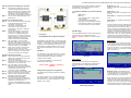
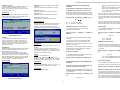
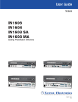
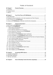
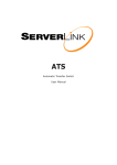
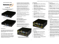
SL-KXSA-300 ServerLink Cat 5 KVM Extender VGA, USB, PS/2, Audio & Serial up to 300mtr Quick Installation Guide SL-KXSA-300 ServerLink CAT5 KVM Extender VGA, USB PS/2 with Audio & RS-232 Serial Transmitter Unit [TX – Front Panel] a. POWER LED (ON: Power on / OFF: Power off) b. LINK LED (ON: Link OK / Flashing: Transmitting / OFF: No Link) c. Mode LED (ON: Full Access / Flashing: View Only / OFF: Deny – Remote Console on RX unit) d. Mode Select Button for Remote Console (Full Access / View Only / Deny) e. USB mouse connector (USB Type A) f. USB keyboard connector (USB Type A) g. Video console port (HDB15, connect to monitor) h. CAT5 Extension Port [RJ-45, connect to the RX unit via a CATx UTP cable] The Receiver Unit has a built-in 2 port KVM switch, and therefore can also be connected to another computer at the receiver end and perform switching between the remote computer (connected to the TX) and the local computer (connected to the RX). Applications include remote access of computers or servers for security reasons, factory floors or warehouses not environmentally suited to a computer or point of sale applications where space for a computer is limited. It allows the user to manage and control the computer at both locations together with the capability of switching between the original computer and a second computer on the Receiver end. [TX – Back Panel] i. Audio connector (3.5mm, connect to speakers/earphones) j. Mic connector (3.5mm, connect to microphone) k. Serial Extension Port (RJ12, connect to serial device) l. Audio connector (3.5mm, connect to computer) m. Mic connector (3.5mm, connect to computer) n. Computer port (HDB15, connect to the 1st computer with included 3-in-1 KVM cable) o. Power receptacle (DC9V 1.7A, centre-positive) This CAT5 KVM Extender also allows its user to upgrade firmware contents whenever is needed to enhance compatibility or functionality. For the flash upgrade procedure, please refer to the Flash Upgrade Operation Guide provided with the new version of Firmware upgrade file. Package Contents Transmitter (TX) unit – Front View Receiver (RX) Unit – Front View Transmitter (TX) Unit x 1 Receiver (RX) Unit x 1 3-in-1 VGA/USB/PS2 KVM Cable x 2 3.5mm Stereo Cable for Audio/Mic x 2 RJ12-to-DB9-Female Cable x 1 RJ12-to-DB9-Male Cable x 1 Power Adapters (DC9V 1.7A) x 2 This Quick Installation Guide x 1 The Mode Select Button on the RX unit (marked “4” on the photo above) allows you to toggle between 1st and 2nd computers. However, whether it toggles the audio/mic channel with the selected computer will depend on the setting of the audio/mic status bound or unbound with the computer. To configure the audio/mic status, you can go to the Audio Setting page of the OSD menu on the RX unit. INSTALLATION Before you install the two pieces of the CAT5 KVM Extender, you should have these items on the checklist ready: 1. 2. 3. The front and back panels are where the various connectors are located on the two pieces of the CAT5 KVM Extender. Before you connect these two units to any computer, cabling accessories or peripherals, you should get a glimpse of the main connectors before setting up the system. 4. Receiver (RX) Unit – Front & Back Panel [Directly connected to the Remote Console] INTRODUCTION The SL-KXSA-300 CAT5 KVM Extender can extend your keyboard, monitor and mouse, together with audio & mic and RS-232 serial control, from your computer up to 300mtr away on a single CAT 5 or CAT 6 UTP cable. The CAT5 KVM Extender comprises two distinct units - the Receiver (RX) Unit and the Transmitter (TX) Unit. The Transmitter is fitted with a local console and allows a user to access the computer at the local end, while, at the same time extending its keyboard, mouse and video, as well as its audio/mic and RS-232 (serial) interface up to 300mtr away to the Receiver unit at the remote end. [RX-Back Panel] 9. Audio connector (3.5mm, connect to speakers/earphones) 10. Mic connector (3.5mm, connect to microphone) 11. Serial Extension Port (RJ12, connect to serial device) 12. Audio connector (3.5mm, connect to 2nd computer) 13. Mic connector (3.5mm, connect to 2nd computer) 14. Computer port (HDB15, connect to the 2nd computer with included 3-in-1 KVM cable) 15. Power receptacle (DC9V 1.7A, centre-positive) Receiver Unit [RX-Front Panel] 1. Power LED (ON: Power on / OFF: Power off) 2. Link LED (ON: Link OK / Flashing: Receiving / OFF: No Link) 3. Remote LED (Remote Console ON/OFF) 4. Mode Select Button (Local/ Remote Computer – with or without audio/mic*) 5. USB mouse connector (USB Type A) 6. USB keyboard connector (USB Type A) 7. Console Video port [HDB15, connect to monitor] 8. CAT5 Extension Port [RJ-45, connect to the TX unit via a CATx UTP cable] Transmitter (TX) Unit – Front & Back Panel [Directly connected to the Computer] 1 5. 6. 7. 8. The computer for extension should be one with either PS/2 or USB interfaces. Prepare 1 or 2 sets of keyboard, mouse, monitor - 1 set for console 1 (on the TX unit) and the other set for console 2 (on the RX unit ). If using a monitor on both sides, the two monitors used (one on the TX side and the other on the RX side) for display should be of the same native resolution to ensure maximum compatibility. You should use standard keyboard and mice, since the CAT5 KVM extender supports only standard 5 button mice and keyboard. Any more advanced mouse/keyboard function may or may not be supported by this CAT5 KVM extender. Use good quality CATx UTP cable (max. 300mtr). Note that good quality cable will give better video outcome over a longer distance. Any cabling distance longer than 300mtr will experience more signal degradation. However, good quality cable can reach even beyond the maximum 300mtr with satisfactory results. The choice of path of the CATx UTP cable should not only take into account the shortest possible path, but also one that is relatively far away from any significant electromagnetic interference source. There should be power outlets near where you locate the extenders. SL-KXSA-300 ServerLink Cat 5 KVM Extender VGA, USB, PS/2, Audio & Serial up to 300mtr Plan the layout path and deploy the UTP cable Step 1. Step 2. Plan the path through which the CATx UTP cable will be deployed across the distance between the Transmitter and the Receiver. You should choose the layout path based on the shortest length and with the least electromagnetic interference. Lay out the UTP cable according to your planned path. Configure the Transmitter Console Step 3. Connect one end of the CATx UTP cable to the CAT5 Extension port of the Transmitter. (connector h) Step 4. Connect the power adapter to the Transmitter to power it up before connecting any computer or cables to it. (connector o) Step5. Connect the computer to the console ports of the Transmitter, using (1) the included 3-in-1 USB/PS2 KVM cable (connector n; if you need to connect to a PS/2 computer, you can add the included USB-to-PS/2 adapter), and (2) the audio/mic cable (connectors l and m). Step 6. Set up Console 1: Connect a USB keyboard, USB mouse, VGA monitor as well as a set of speakers, microphone & serial device to the Transmitter’s Console ports (connectors e, f, g, I, j and k). Step 7. Power on the computer, and check the keyboard, mouse, video, as well as speakers and mic on Console 1 to see if it works fine. Make sure it is working fine before you proceed to the next steps. Configure the Receiver Console Step 8. Connect the other end of the CATx UTP cable to the CAT5 Extension port of the Receiver (connector 8). Step 9. Connect the power adapter to the Receiver to power it up before connecting any devices to it. (connector 15) Step 10. Set up Console 2: Connect a USB keyboard, USB mouse, VGA monitor as well speakers, microphone & serial device to the Receiver’s Console ports (connectors 5, 6, 7, 9, 10 and 11). Step 11. Check the keyboard, mouse, video, audio and mic on Console 2 are working fine. Step 12. Adjust the video parameters to optimize the display output (Refer to OSD Menu/Video section for details). Step 13. You can connect a second computer to the Receiver if needed: Just connect the computer to the computer port (connectors 12. 13 and 14) by using the included 3-in-1 KVM cable and audio/mic cable. Each keystroke within a hotkey sequence should be pressed within 2 seconds. Otherwise, the hotkey sequence will not be validated. Brightness: [0 ~ 63] Adjust the Brightness of the Display on Receiver Console. To navigate the OSD Menu, just use the following keys Sharpness: [0 ~ 63] Adjust the Sharpness of the Display on Receiver Console. Enter: Select Esc: Exit, Left/Right cursor: change value in the menu option Up/Down Cursor: Navigate. F10: Logout of the OSD Menu (However, if the password protection is not enabled, the Logout feature will not be available) OSD Main page This is the OSD Main Menu and is the first page you will see when you hit the keyboard hotkey SCROLL+ SCROLL+ SPACE - to invoke the OSD Menu. CAT5 KVM Extender Configuration Diagram Phase Red: [0 ~ 63] specify the time delay for red colour. Phase Green: [0 ~ 63] specify the time delay for green colour. The blue component colour is adjusted automatically in proportion to the red and green. Users have no need to adjust the blue colour themselves. In order to achieve optimized video output on the console that may be up to 300mtr away from the computer, users could adjust these various parameters to achieve an optimized video output on the console monitor. For a general guideline of how to adjust your video display parameters on the remote console, please refer to next section, Optimize the Video Display on the Remote Console. Audio Setting KVM Switch Console Extension: You can also utilize the CAT5 KVM Extender to extend your KVM Switch Console …. Just connect the Transmitter unit to the console port of the KVM Switch, and the rest of the connections are as descried above. Thus, you can also extend the KVM switch console up to 300mtr away. On this page, you can configure the audio settings on the RX unit and the TX unit. On the RX unit, you can configure the audio to be either fixed on the local PC or the remote PC, or to be bound with the switching of the PC. You can also turn ON/OFF the audio on the TX unit. OSD Menu The OSD Menu control is available only on the RX unit. By using the OSD Menu, you can enjoy more intuitive KVM switching operations and easily configure various settings: Main Menu Video Setting To invoke the OSD Menu, you should hit the following keyboard hotkeys: Here you can enter a submenu to configure the video settings such as Brightness, Sharpness and skew compensation for Phase Red and Phase Green. Default Hotkey = [SCROLL] + [SCROLL] + [SPACE] Audio Setting Submenu Hotkey preceding sequence configuration: RX Audio: [BIND/Local PC/Remote PC] Configure the RX Audio to be fixed at the Local PC or at the Remote PC, or bound with the computer channel switching on the RX console. The default hotkey preceding sequence is SCROLL + SCROLL. For users who want to use a preceding sequence other than SCROLL, you can go to the OSD Menu and choose any one of the 4 alternatives – CAPS, SCROLL, F12 or NUM. Video Setting Submenu 2 Since the RX unit has a built-in KVM switching feature that allows switching between the remote computer and an (extra) local computer connected in proximity, one can use the RX audio setting to configure whether the audio switching should go with the computer switching or remain independent. SL-KXSA-300 ServerLink Cat 5 KVM Extender VGA, USB, PS/2, Audio & Serial up to 300mtr TX Audio: [ON/OFF] Activate or deactivate the TX Audio (and Mic) on the TX unit. When the TX audio is OFF, you can no longer hear the sound or use the microphone on the computer on the TX unit. HOTKEYS AVAILABLE ON THE RECEIVER CONSOLE Baud Rate: [9600, 14400, 19200, 38400, 57600, 115200] Select the Baud Rate of the RS-232 connection. Switch between Local/Remote Computer using Keyboard Hotkey (on Receiver console only) Data bits: [5, 6, 7, 8] Select the Data bits of the RS-232 connection. EDID Setting The EDID setting on the RX can either be configured as the same as the monitor on the computer on the TX, or as the monitor used on the RX. In addition to using the switching button on the front panel of the Receiver to switch between the 1st and 2nd computer, you can also use the keyboard hotkey: Stop bits: [1, 2] Select the Stop bits of the RS-232 connection. Parity: [Odd, Even, None] Select the Parity of the RS-232 connection. Hotkey sequence = [SCROLL] + [SCROLL] + (y) (y) = 1, Full access (keyboard, mouse and video) (y) = 2, Access Denied (no keyboard or mouse control and blank screen) (y) = 3, View Only (only video with no mouse or keyboard control) When the remote console is turned OFF, the video screen will become blank and the keyboard and mouse will be disabled. This provides a security measure to block or grant access on the remote console. (y) = , Password Setting Disable / Enable the password protection feature. If enabled, after you log out or the Auto logout has timed out, you will be prompted for the correct password before you can access the console again. (y) = , Local (2nd computer) (y) = , Remote (1st Computer) When the remote console is in View Only Mode, the user can only see the screen while access to keyboard and mouse control are not available. OSD Menu (on Receiver console only) Audio ON/OFF To invoke the OSD Menu, you should hit the following keyboard hotkeys: To turn ON/OFF the Audio on the TX console, hit the following hotkey commands: Hotkey Sequence = [SCROLL] + [SCROLL] + [SPACE] Hotkey sequence = [SCROLL] + [SCROLL] + A + (y) EDID Setting Submenu TX EDID You can select the TX EDID emulation data set to adopt - either that of the monitor on the RX or the monitor on the TX unit. However, before you can make the selection for the first time, you may need to read the monitor EDID information by the Read Monitor option below. Read Monitor Reads the EDID configuration data from the monitors on the TX and the RX and stores it for use for the EDID emulation on the TX unit. Note that the RX unit will always utilize the EDID configuration data from the monitor connected to the RX unit itself. However, the TX unit is able to use the EDID configuration data from the monitor connected to the TX unit itself or the EDIDI configuration data from the monitor connected to the RX unit. (y) = 0, 1 The hotkey preceding sequence default is SCROLL + SCROLL. For users who want to use a different preceding hotkey sequence can go to the OSD Menu and choose any one of the 4 following hotkeys – CAPS, SCROLL, F12 or NUM. Auto Logout [0 ~ 10] Disable / Enable the Logout timeout (0~10min, 0 = Disable). The Auto logout time can be configured from 0 (Disable), with an increment of 1, right up to 10 min. If the password protection is not enabled, the Auto logout will not be available for use. Each keystroke within a hotkey sequence should be pressed within 2 seconds. Otherwise, the hotkey sequence will not be validated. Buzzer Sound ON/OFF Hotkey [SCROLL, CAPS, NUM, F12] By default, the hotkey preceding sequence is SCROLL + SCROLL. However it can be changed to an alternative hotkey such as CAPS, F12 or NUM. To turn ON/OFF the buzzer sound on the Receiver, hit the following hotkey commands: OSD Timeout [0~63] Configure the OSD timeout value (0, 20~...30~…60), with an increment of 5 seconds, (0 = Disable). HOTKEYS AVAILABLE ON THE TRANSMITTER CONSOLE Hotkey sequence = [SCROLL] + [SCROLL] + B (y) = 0, Audio OFF (y) = 1, Audio ON EDID Emulation Data Select To select the EDID configuration data set to be used on the TX unit, (you can copy from either the RX monitor or TX monitor), just hit the following hotkey commands: Hotkey sequence = [SCROLL] + [SCROLL] + D + (y) (y) = 1, 2 (y) = 1, Set to EDID data set from RX monitor (y) = 2, Set to EDID data set from TX monitor Buzzer Sound ON/OFF RS-232 Setting Change the Remote Console ON/OFF/View Only mode (on Transmitter console only) Load Default Load factory default settings. While you are at the Transmitter Console, you can turn Remote Console On/Off or make it View Only by the following: Hotkey sequence = [SCROLL] + [SCROLL] + M + (y) (y) = 1, 2, 3 RS-232 Setting Submenu 3 To turn ON/OFF the buzzer sound on the Transmitter, just hit the following hotkey commands: Hotkey sequence = [SCROLL] + [SCROLL] + B Microphone Usage on RX and TX console If you have used a microphone on the RX console, note that the microphone input on the RX console will always be directed to the computer connected on the TX end. That simply means that if another person happens to use a recording application on the TX end, he will pick up sound stream not only SL-KXSA-300 ServerLink Cat 5 KVM Extender VGA, USB, PS/2, Audio & Serial up to 300mtr from microphone on the TX but also from that on the RX at the same time. then move on to adjusting the Red Delay and Green Delay to achieve your optimized video output. This special feature will allow both admins on both RX console and TX console to mix their sound input to same application on the TX console, so that both admins can communicate with the same third-party counterpart. Step 3. Adjust the Red Delay and Green Delay: the Red, Green and Blue are the primary colors that constitute our color perception scheme on the monitor. However, if you want to shut off the sound input from the RX and use only that from the TX, you can just configure the RX console to be OFF (Deny Access), so that you won’t have mixed sound input coming from the RX console microphone. Optimize the Video Display on the Remote Console To achieve an optimized display output on the remote console (i.e. the Receiver) you will need to adjust the various video parameters such as Brightness and Sharpness in an optimized combination that gives you the best video display. Please follow the procedure below to achieve an optimized display output on your remote console screen (on RX unit): Step 1. Choose a video display content that you think will be suitable to serve as a reference for the visual adjustment. You can choose a document that integrates texts and graphics so that you can use it as a reference to achieve an optimized video display for either textual or graphical content on the Receiver video output. One alternative can be the visual testing program provided by the display card vendor. Step 2. Adjust the Brightness and Sharpness - First, invoke the OSD menu by hitting the hotkey, SCROLL + SCROLL + Space, then go to the Video Setting submenu. Next, adjust your video display for an optimized output. The Brightness adjustment can help you to tune the picture luminance as a whole to lighter or darker output that best suits your visual perception. The Sharpness is the edge contrast that you will perceive. Adjust the Brightness: The brighter the picture, the more luminance will be added to the picture as a whole. Adjust the Sharpness: To add more sharpness to the picture is to help you distinguish more detail out of the edges of a line or shape. FCC This equipment has been tested and found to comply with Part 15 of the FCC Rules. Operation is subject to the following two conditions: (1) This device may not cause harmful interference (2) This device must accept any interference received. Including interference that may cause undesired operation. The CAT5 extender uses different wires in the UTP cable to carry the signals of different primary colors. The different wires in the twisted-paired cable are all slightly different overall lengths and the longer the CATx cable, the greater the difference in length between wires. CE This equipment is in compliance with the requirements of the following regulations: EN 55 022: CLASS B. C-Tick This equipment is in compliance with ACMA’s Electromagnetic Compatibility (EMC) regulatory arrangements under the Radiocommunications Act 1992. This difference in length causes the red, green and blue colours to become out of sync. You will need to adjust the delay time for certain colour signals on certain wires to make the three colour signals arrive into the display in good sync. RoHS All contents of this package, including products, packing materials and documentation comply with RoHS. The CAT5 KVM Extender requires you to manually adjust only the Red delay and the Green delay - the Blue delay is automatically tuned and optimized by the machine according to the other concurrent video parameters. The values of the Red delay and the Green delay will be limited within a preset difference range. This means, whenever you try to adjust either the value of the Red delay or the Green delay to be outside of the allowable preset difference range as compared to the value of the other colour delay, the other colour delay will be automatically adjusted to be within the difference range to prevent the video from being perceptibly disoriented. With the Blue delay automatically tuned in relation to the other colours and the Red and Green delays limited within a comfortable difference range, the SLKXSA-300 CAT5 KVM extender facilitates an easier and more intuitive way for video optimization. No Video Troubleshooting Q. When I connect a monitor to the CAT5 KVM extender, it does not display any video. A. If you encounter no video or other display problems with a specific monitor, you should try to copy the EDID information from the smaller monitor among the local monitor and the remote monitor to see if this can eliminate the display problem. When you have adjusted the Brightness and Sharpness to achieve your desired level, you can 4