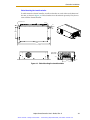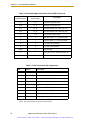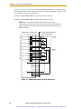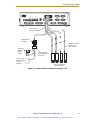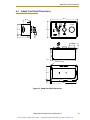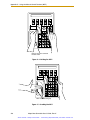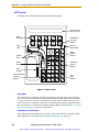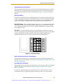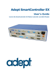
1
Looking for more information?
Visit us on the web at http://www.artisan-scientific.com for more information:
• Price Quotations • Drivers· Technical Specifications. Manuals and Documentation
Artisan Scientific is You~ Source for: Quality New and Certified-Used/Pre:-awned ECJuiflment
• Fast Shipping and DelIve1y
• Tens of Thousands of In-Stock Items
• Equipment Demos
• Hundreds of Manufacturers Supported
• Leasing / Monthly Rentals
Service Center Repairs
Experienced Engineers and Technicians on staff in our
State-of-the-art Full-Service In-House Service Center Facility
• Consignment
InstraView Remote Inspection
Remotely inspect equipment before purchasing with our
Innovative InstraView-website at http://www.instraview.com
We bUy used equipment! We also offer credit for Buy-Backs and Trade-Ins
Sell your excess. underutilized. and idle used equipment. Contact one of our Customer Service Representatives todayl
Talk to a live person: 88EM38-S0URCE fB88-887-68721 I Contact us by email: [email protected] I Visit our website: http://www.artisan-scientific.com
Adept SmartController
User’s Guide
Covers the SmartController and sDIO Module
SmartServo
OK
HPE
LAN
SF
ES
HD
1.1
SW1
1 2 3 4
1.2
IEEE-1394
2.1
Device Net
2.2
RS-232/TERM
RS-422/485
RS-232-1
RS-232-2
Eth 10/100
BELT ENCODER
ON
OFF
1
2
3
XDIO
XUSR
XSYS
XFP
XMCP
XDC1 XDC2
24V
5A
-+
-+
Artisan Scientific - Quality Instrumentation ... Guaranteed | (888) 88-SOURCE | www.artisan-scientific.com
SmartController CX
*S/N 3562-XXXXX*
CAMERA
R
Artisan Scientific - Quality Instrumentation ... Guaranteed | (888) 88-SOURCE | www.artisan-scientific.com
Adept SmartController
User’s Guide
Covers the SmartController and sDIO Module
SmartServo
OK
HPE
LAN
SF
ES
HD
1.1
SW1
1 2 3 4
1.2
IEEE-1394
2.1
Device Net
2.2
RS-232/TERM
RS-422/485
RS-232-1
RS-232-2
Eth 10/100
BELT ENCODER
ON
OFF
1
2
3
XDIO
XUSR
XSYS
XFP
XMCP
XDC1 XDC2
24V
5A
-+
-+
SmartController CX
*S/N 3562-XXXXX*
CAMERA
R
P/N: 00356-00100, Rev. H
June, 2009
5960 Inglewood Drive • Pleasanton, CA 94588 • USA • Phone 925.245.3400 • Fax 925.960.0452
Otto-Hahn-Strasse 23 • 44227 Dortmund • Germany • Phone +49.231.75.89.40 • Fax +49.231.75.89.450
Block 5000 Ang Mo Kio Avenue 5 • #05-12 Techplace II • Singapore 569870 • Phone +65.6755 2258 • Fax +65.6755 0598
Artisan Scientific - Quality Instrumentation ... Guaranteed | (888) 88-SOURCE | www.artisan-scientific.com
The information contained herein is the property of Adept Technology, Inc., and shall not be reproduced
in whole or in part without prior written approval of Adept Technology, Inc. The information herein is subject to change without notice and should not be construed as a commitment by Adept Technology, Inc. This
manual is periodically reviewed and revised.
Adept Technology, Inc., assumes no responsibility for any errors or omissions in this document. Critical
evaluation of this manual by the user is welcomed. Your comments assist us in preparation of future documentation. Please email your comments to: [email protected].
Copyright © 2003-2009 by Adept Technology, Inc. All rights reserved.
Adept, the Adept logo, the Adept Technology logo, AdeptVision, AIM, Blox, Bloxview, FireBlox,
Fireview, HexSight, Meta Controls, MetaControls, Metawire, Soft Machines, and Visual Machines
are registered trademarks of Adept Technology, Inc.
Brain on Board is a registered trademark of Adept Technology, Inc. in Germany.
Adept ACE, ACE PackXpert, Adept 1060 / 1060+, Adept 1850 / 1850 XP, Adept 540 Adept 560, Adept
AnyFeeder, Adept Award, Adept C40, Adept C60, Adept CC, Adept Cobra 350, Adept Cobra 350 CR/ESD,
Adept Cobra 550, Adept 550 CleanRoom, Adept Cobra 600, Adept Cobra 800, Adept Cobra i600, Adept
Cobra i800, Adept Cobra PLC server, Adept Cobra PLC800, Adept Cobra s600, Adept Cobra s800, Adept
Cobra s800 Inverted, Adept Cobra s850, Adept Cobra Smart600, Adept Cobra Smart800, Adept DeskTop,
Adept FFE, Adept FlexFeeder 250, Adept IC, Adept iSight, Adept Impulse Feeder, Adept LineVision, Adept
MB-10 ServoKit, Adept MC, Adept MotionBlox-10, Adept MotionBlox-40L, Adept MotionBlox-40R, Adept
MV Adept MV-10, Adept MV-19, Adept MV4, Adept MV-5, Adept MV-8, Adept OC, Adept Python, Adept
Quattro s650, Adept Quattro s650H, Adept sDIO, Adept SmartAmp, Adept SmartAxis, Adept
SmartController CS, Adept SmartController CX, Adept SmartModule, Adept SmartMotion, Adept
SmartServo, Adept sMI6, Adept sSight, Adept Viper s650, Adept Viper s850, Adept Viper s1300, Adept
Viper s1700, AdeptCartesian, AdeptCast, AdeptForce, AdeptFTP, AdeptGEM, AdeptModules,
AdeptMotion, AdeptMotion Servo, AdeptMotion VME, AdeptNet, AdeptNFS, AdeptOne, AdeptOne-MV,
AdeptOne-XL, AdeptRAPID, AdeptSight, AdeptSix, AdeptSix 300, AdeptSix 300 CL, AdeptSix 300 CR,
AdeptSix 600, AdeptTCP/IP, AdeptThree, AdeptThree-MV, AdeptThree-XL, AdeptTwo, AdeptVision,
AVI AdeptVision, AGS AdeptVision GV, AdeptVision I, AdeptVision II, AdeptVision VME, AdeptVision
VXL, AdeptVision XGS, AdeptVision XGS II, AdeptWindows, AdeptWindows Controller, AdeptWindows
DDE, AdeptWindows Offline Editor, AdeptWindows PC, AIM Command Server, AIM Dispense, AIM
PCB, AIM VisionWare, A-Series, FlexFeedWare, HyperDrive, IO Blox, MicroV+, MotionBlox, MotionWare,
ObjectFinder, ObjectFinder 2000, PackOne, PalletWare, sAVI, S-Series, UltraOne, V, V+ and VisionTeach
are trademarks of Adept Technology, Inc.
Any trademarks from other companies used in this publication
are the property of those respective companies.
Printed in the United States of America
Artisan Scientific - Quality Instrumentation ... Guaranteed | (888) 88-SOURCE | www.artisan-scientific.com
Table of Contents
1
Introduction . . . . . . . . . . . . . . . . . . . . . . . . . . . . . . . . . . . . . . . . . . . . . . . 15
1.1 Product Description. . . . . . . . . . . . . . . . . . . . . . . . . . . . . . . . . . . . . . . . . . . . . . . . 15
Adept SmartController CS. . . . . . . . . . . . . . . . . . . . . . . . . . . . . . . . . . . . . . . .
Adept SmartController CX . . . . . . . . . . . . . . . . . . . . . . . . . . . . . . . . . . . . . . .
sDIO Expansion Module. . . . . . . . . . . . . . . . . . . . . . . . . . . . . . . . . . . . . . . . . .
Optional Adept T1/T2 Pendant . . . . . . . . . . . . . . . . . . . . . . . . . . . . . . . . . . .
15
15
16
16
1.2 Manufacturer’s Declaration . . . . . . . . . . . . . . . . . . . . . . . . . . . . . . . . . . . . . . . . . 16
1.3 How Can I Get Help? . . . . . . . . . . . . . . . . . . . . . . . . . . . . . . . . . . . . . . . . . . . . . . 17
Related Manuals . . . . . . . . . . . . . . . . . . . . . . . . . . . . . . . . . . . . . . . . . . . . . . . 17
Adept Document Library . . . . . . . . . . . . . . . . . . . . . . . . . . . . . . . . . . . . . . . . 18
1.4 Dangers, Warnings, Cautions, and Notes in Manual . . . . . . . . . . . . . . . . . . . . . 18
1.5 Safety . . . . . . . . . . . . . . . . . . . . . . . . . . . . . . . . . . . . . . . . . . . . . . . . . . . . . . . . . . . 19
Reading and Training for Users and Operators . . . . . . . . . . . . . . . . . . . . . .
System Safeguards. . . . . . . . . . . . . . . . . . . . . . . . . . . . . . . . . . . . . . . . . . . . . .
Safety Features on the Front Panel . . . . . . . . . . . . . . . . . . . . . . . . .
Computer-Controlled Robots and Motion Devices . . . . . . . . . . . .
Manually Controlled Robots and Motion Devices . . . . . . . . . . . . .
Other Computer-Controlled Devices . . . . . . . . . . . . . . . . . . . . . . . .
Program Security . . . . . . . . . . . . . . . . . . . . . . . . . . . . . . . . . . . . . . . . . . . . . . .
Inappropriate Uses of the Adept SmartController . . . . . . . . . . . . . . . . . . . .
19
20
20
20
20
20
21
21
1.6 Standards Compliance . . . . . . . . . . . . . . . . . . . . . . . . . . . . . . . . . . . . . . . . . . . . 21
1.7 CAT-3 Version of SmartController . . . . . . . . . . . . . . . . . . . . . . . . . . . . . . . . . . . . 22
Identification . . . . . . . . . . . . . . . . . . . . . . . . . . . . . . . . . . . . . . . . . . . . . . . . . .
Functionality Changes . . . . . . . . . . . . . . . . . . . . . . . . . . . . . . . . . . . . . . . . . .
Pendant Enable Switch Not Functional in Auto Mode . . . . . . . . .
High Power Indication on XDIO Connector. . . . . . . . . . . . . . . . . . .
E-Stop Circuit . . . . . . . . . . . . . . . . . . . . . . . . . . . . . . . . . . . . . . . . . . . . . . . . . .
Operational Change in SmartModule Systems . . . . . . . . . . . . . . . . . . . . . .
2
22
23
23
23
23
24
SmartController Installation . . . . . . . . . . . . . . . . . . . . . . . . . . . . . . . . . . 25
2.1 Controller Installation . . . . . . . . . . . . . . . . . . . . . . . . . . . . . . . . . . . . . . . . . . . . . . 25
Before Unpacking . . . . . . . . . . . . . . . . . . . . . . . . . . . . . . . . . . . . . . . . . . . . . .
Upon Unpacking . . . . . . . . . . . . . . . . . . . . . . . . . . . . . . . . . . . . . . . . . . . . . . .
Repacking for Relocation . . . . . . . . . . . . . . . . . . . . . . . . . . . . . . . . . . . . . . . .
Space Around the Chassis . . . . . . . . . . . . . . . . . . . . . . . . . . . . . . . . . . . . . . .
Adept SmartController User’s Guide, Rev. H
Artisan Scientific - Quality Instrumentation ... Guaranteed | (888) 88-SOURCE | www.artisan-scientific.com
25
25
26
26
5
Table of Contents
Mounting the SmartController . . . . . . . . . . . . . . . . . . . . . . . . . . . . . . . . . . . . . 26
Rack-Mounting the SmartController . . . . . . . . . . . . . . . . . . . . . . . . . 27
Panel-Mounting the SmartController . . . . . . . . . . . . . . . . . . . . . . . . . 28
Table-Mounting the SmartController . . . . . . . . . . . . . . . . . . . . . . . . . 29
Stack-Mounting Components . . . . . . . . . . . . . . . . . . . . . . . . . . . . . . 30
CompactFlash Memory Card . . . . . . . . . . . . . . . . . . . . . . . . . . . . . . . . . . . . . 30
Removing CompactFlash . . . . . . . . . . . . . . . . . . . . . . . . . . . . . . . . . . 31
Installing CompactFlash . . . . . . . . . . . . . . . . . . . . . . . . . . . . . . . . . . . 31
Connecting Power . . . . . . . . . . . . . . . . . . . . . . . . . . . . . . . . . . . . . . . . . . . . . . 32
24 VDC Power Specifications . . . . . . . . . . . . . . . . . . . . . . . . . . . . . . 32
24 VDC Power Cabling . . . . . . . . . . . . . . . . . . . . . . . . . . . . . . . . . . . . 33
Daisy-Chaining Power . . . . . . . . . . . . . . . . . . . . . . . . . . . . . . . . . . . . . 33
Grounding . . . . . . . . . . . . . . . . . . . . . . . . . . . . . . . . . . . . . . . . . . . . . . 33
Installing 24 VDC Connectors . . . . . . . . . . . . . . . . . . . . . . . . . . . . . . 34
IEEE 1394 Cable Specifications . . . . . . . . . . . . . . . . . . . . . . . . . . . . . . . . . . . . 35
2.2 System Cable Installation . . . . . . . . . . . . . . . . . . . . . . . . . . . . . . . . . . . . . . . . . . . 35
3
SmartController Operation . . . . . . . . . . . . . . . . . . . . . . . . . . . . . . . . . . . 37
3.1 SmartController CS Connectors and Indicators . . . . . . . . . . . . . . . . . . . . . . . . . 37
3.2 SmartController CX Connectors and Indicators . . . . . . . . . . . . . . . . . . . . . . . . . 40
3.3 Front Panel . . . . . . . . . . . . . . . . . . . . . . . . . . . . . . . . . . . . . . . . . . . . . . . . . . . . . . . 41
3.4 Configuring the Controller. . . . . . . . . . . . . . . . . . . . . . . . . . . . . . . . . . . . . . . . . . . 42
Factory Default Settings . . . . . . . . . . . . . . . . . . . . . . . . . . . . . . . . . . . . . . . . . . 42
DIP-Switch Settings . . . . . . . . . . . . . . . . . . . . . . . . . . . . . . . . . . . . . . . . . . . . . . 42
AdeptWindows PC Graphical User Interface. . . . . . . . . . . . . . . . . . 43
ASCII Terminal . . . . . . . . . . . . . . . . . . . . . . . . . . . . . . . . . . . . . . . . . . . . 43
AUTO Boot. . . . . . . . . . . . . . . . . . . . . . . . . . . . . . . . . . . . . . . . . . . . . . . 44
3.5 SmartController Serial I/O Connectors . . . . . . . . . . . . . . . . . . . . . . . . . . . . . . . . 44
RS-232 Connectors . . . . . . . . . . . . . . . . . . . . . . . . . . . . . . . . . . . . . . . . . . . . . . 44
RS-422/485 Connector . . . . . . . . . . . . . . . . . . . . . . . . . . . . . . . . . . . . . . . . . . . 45
3.6 Installing the User Interface . . . . . . . . . . . . . . . . . . . . . . . . . . . . . . . . . . . . . . . . . 46
Graphical Interface Using AdeptWindows . . . . . . . . . . . . . . . . . . . . . . . . . . 46
Graphical Interface Using Adept DeskTop . . . . . . . . . . . . . . . . . . . . . . . . . . 46
Text Interface Using a PC with HyperTerminal Software. . . . . . . . . . . . . . . . 47
Installation Procedure . . . . . . . . . . . . . . . . . . . . . . . . . . . . . . . . . . . . . 47
Text Interface Using a Terminal . . . . . . . . . . . . . . . . . . . . . . . . . . . . . . . . . . . . 48
Recommended Terminal for Text-Based Systems . . . . . . . . . . . . . . 48
Installation Procedure . . . . . . . . . . . . . . . . . . . . . . . . . . . . . . . . . . . . . 48
3.7 Connecting Customer-Supplied Safety and Power-Control Equipment . . . . . 49
Connecting Equipment to the System . . . . . . . . . . . . . . . . . . . . . . . . . . . . . . 49
Emergency Stop Circuits . . . . . . . . . . . . . . . . . . . . . . . . . . . . . . . . . . . . . . . . . 54
User E-Stop Indication - Remote Sensing of E-Stop . . . . . . . . . . . . . 55
Line E-Stop Input. . . . . . . . . . . . . . . . . . . . . . . . . . . . . . . . . . . . . . . . . . 55
Muted Safety Gate E-Stop Circuitry. . . . . . . . . . . . . . . . . . . . . . . . . . 55
6
Adept SmartController User’s Guide, Rev. H
Artisan Scientific - Quality Instrumentation ... Guaranteed | (888) 88-SOURCE | www.artisan-scientific.com
Table of Contents
Remote Manual Mode . . . . . . . . . . . . . . . . . . . . . . . . . . . . . . . . . . . . . . . . . .
User Manual/Auto Indication . . . . . . . . . . . . . . . . . . . . . . . . . . . . . . . . . . . .
User High Power On Indication . . . . . . . . . . . . . . . . . . . . . . . . . . . . . . . . . . .
Remote High Power On/Off Control . . . . . . . . . . . . . . . . . . . . . . . . . . . . . . .
High Power On/Off Lamp . . . . . . . . . . . . . . . . . . . . . . . . . . . . . . . . . . . . . . .
Remote Front Panel or User-Supplied Control Panel Usage . . . . . . . . . . . .
Remote Pendant Usage . . . . . . . . . . . . . . . . . . . . . . . . . . . . . . . . . . . . . . . . .
56
56
56
57
57
57
58
3.8 Connecting Customer-Supplied Digital I/O Equipment . . . . . . . . . . . . . . . . . . 59
DeviceNet Connector. . . . . . . . . . . . . . . . . . . . . . . . . . . . . . . . . . . . . . . . . . .
XDIO Connector. . . . . . . . . . . . . . . . . . . . . . . . . . . . . . . . . . . . . . . . . . . . . . . .
Input Signals. . . . . . . . . . . . . . . . . . . . . . . . . . . . . . . . . . . . . . . . . . . . .
REACT Input Signals 1001 to 1012 . . . . . . . . . . . . . . . . . . . . . . . . . . .
Fast Input Signals 1001 to 1004 . . . . . . . . . . . . . . . . . . . . . . . . . . . . .
Output Signals . . . . . . . . . . . . . . . . . . . . . . . . . . . . . . . . . . . . . . . . . . .
Digital I/O Connector Ordering Details (Third-Party Sources) . . . .
Screw-Terminal Field-Wiring Adapter Blocks . . . . . . . . . . . . . . . . . .
59
59
59
61
61
61
63
64
3.9 Belt Encoder Interface on SmartController CX. . . . . . . . . . . . . . . . . . . . . . . . . . 65
4
AdeptVision sAVI Option . . . . . . . . . . . . . . . . . . . . . . . . . . . . . . . . . . . . 67
4.1 Introduction . . . . . . . . . . . . . . . . . . . . . . . . . . . . . . . . . . . . . . . . . . . . . . . . . . . . . . 67
sAVI Board Features . . . . . . . . . . . . . . . . . . . . . . . . . . . . . . . . . . . . . . . . . . . .
sAVI Board System Requirements . . . . . . . . . . . . . . . . . . . . . . . . . . . . . . . . . .
Pixel Format . . . . . . . . . . . . . . . . . . . . . . . . . . . . . . . . . . . . . . . . . . . . . . . . . . .
AdeptVision sAVI Inspection System Limitations . . . . . . . . . . . . . . . . . . . . .
67
67
68
68
4.2 Camera Compatibility . . . . . . . . . . . . . . . . . . . . . . . . . . . . . . . . . . . . . . . . . . . . . 68
Guidelines for Cameras. . . . . . . . . . . . . . . . . . . . . . . . . . . . . . . . . . . . . . . . . . 68
Cameras Supported . . . . . . . . . . . . . . . . . . . . . . . . . . . . . . . . . . . . . . . . . . . . 69
Downloading Custom Camera Models . . . . . . . . . . . . . . . . . . . . . . . . . . . . 69
4.3 Camera Cables . . . . . . . . . . . . . . . . . . . . . . . . . . . . . . . . . . . . . . . . . . . . . . . . . . 69
Two-Camera Breakout Cable for RS-170 Cameras . . . . . . . . . . . . . . . . . . . 69
Four-Camera Breakout Cable for RS-170 Cameras . . . . . . . . . . . . . . . . . . . 70
10-Meter Camera Extension Cables . . . . . . . . . . . . . . . . . . . . . . . . . . . . . . . 71
4.4 Installing Camera Cables . . . . . . . . . . . . . . . . . . . . . . . . . . . . . . . . . . . . . . . . . . 72
Connecting the Cables to the RS-170 Standard Camera . . . . . . . . . . . . . 72
4.5 Camera Cable Pin and Signal Information . . . . . . . . . . . . . . . . . . . . . . . . . . . . 74
4.6 sAVI Board Specifications . . . . . . . . . . . . . . . . . . . . . . . . . . . . . . . . . . . . . . . . . . 81
5
SmartController Maintenance . . . . . . . . . . . . . . . . . . . . . . . . . . . . . . . . 83
5.1 Changing the Lamp in the Front Panel High-Power Indicator . . . . . . . . . . . . . 83
Adept SmartController User’s Guide, Rev. H
Artisan Scientific - Quality Instrumentation ... Guaranteed | (888) 88-SOURCE | www.artisan-scientific.com
7
Table of Contents
6
Technical Specifications . . . . . . . . . . . . . . . . . . . . . . . . . . . . . . . . . . . . . 85
6.1 SmartController Dimensions . . . . . . . . . . . . . . . . . . . . . . . . . . . . . . . . . . . . . . . . . 85
6.2 sDIO Dimensions . . . . . . . . . . . . . . . . . . . . . . . . . . . . . . . . . . . . . . . . . . . . . . . . . . 86
6.3 Adept Front Panel Dimensions . . . . . . . . . . . . . . . . . . . . . . . . . . . . . . . . . . . . . . . 87
6.4 Adept T2 Pendant Dimensions . . . . . . . . . . . . . . . . . . . . . . . . . . . . . . . . . . . . . . . 88
6.5 Adept T1 Pendant Dimensions . . . . . . . . . . . . . . . . . . . . . . . . . . . . . . . . . . . . . . . 89
6.6 Adept MCP Dimensions . . . . . . . . . . . . . . . . . . . . . . . . . . . . . . . . . . . . . . . . . . . . 90
A
sDIO Module . . . . . . . . . . . . . . . . . . . . . . . . . . . . . . . . . . . . . . . . . . . . . . . 93
A.1 Mounting the sDIO . . . . . . . . . . . . . . . . . . . . . . . . . . . . . . . . . . . . . . . . . . . . . . . . 93
Rack-Mounting the sDIO . . . . . . . . . . . . . . . . . . . . . . . . . . . . . . . . . . . . . . . . . 94
Panel-Mounting the sDIO . . . . . . . . . . . . . . . . . . . . . . . . . . . . . . . . . . . . . . . . . 95
Table-Mounting the sDIO . . . . . . . . . . . . . . . . . . . . . . . . . . . . . . . . . . . . . . . . . 96
Stack-Mounting the sDIO . . . . . . . . . . . . . . . . . . . . . . . . . . . . . . . . . . . . . . . . . 96
A.2 Installing the sDIO . . . . . . . . . . . . . . . . . . . . . . . . . . . . . . . . . . . . . . . . . . . . . . . . . 96
A.3 Configuring an sDIO . . . . . . . . . . . . . . . . . . . . . . . . . . . . . . . . . . . . . . . . . . . . . . . 97
Default sDIO I/O Configuration . . . . . . . . . . . . . . . . . . . . . . . . . . . . . . . . . . . . 97
Modifying the Default sDIO Configuration. . . . . . . . . . . . . . . . . . . . . . . . . . . 98
Assigning sDIO Signal Blocks . . . . . . . . . . . . . . . . . . . . . . . . . . . . . . . . 98
Assigning I/O Signal Numbers . . . . . . . . . . . . . . . . . . . . . . . . . . . . . . . 99
sDIO Signal Mapping Example 1 . . . . . . . . . . . . . . . . . . . . . . . . . . . 101
sDIO Signal Mapping Example 2 . . . . . . . . . . . . . . . . . . . . . . . . . . . 101
A.4 Using Multiple sDIO Modules . . . . . . . . . . . . . . . . . . . . . . . . . . . . . . . . . . . . . . . 102
A.5 sDIO Module Connectors and Indicators . . . . . . . . . . . . . . . . . . . . . . . . . . . . 103
A.6 sDIO Digital I/O Signals . . . . . . . . . . . . . . . . . . . . . . . . . . . . . . . . . . . . . . . . . . . 104
sDIO Inputs . . . . . . . . . . . . . . . . . . . . . . . . . . . . . . . . . . . . . . . . . . . . . . . . . . . . 104
sDIO Outputs . . . . . . . . . . . . . . . . . . . . . . . . . . . . . . . . . . . . . . . . . . . . . . . . . . 106
Testing sDIO Outputs . . . . . . . . . . . . . . . . . . . . . . . . . . . . . . . . . . . . . 106
sDIO LEDs. . . . . . . . . . . . . . . . . . . . . . . . . . . . . . . . . . . . . . . . . . . . . . . 106
sDIO Output Power Supply Current Selection . . . . . . . . . . . . . . . . 107
Optional DIO Cables . . . . . . . . . . . . . . . . . . . . . . . . . . . . . . . . . . . . . . . . . . . 109
Labeling Cables . . . . . . . . . . . . . . . . . . . . . . . . . . . . . . . . . . . . . . . . . 110
Input and Output Cable Wiring Information . . . . . . . . . . . . . . . . . 111
B
Adept DeviceNet . . . . . . . . . . . . . . . . . . . . . . . . . . . . . . . . . . . . . . . . . . 115
B.1 DeviceNet Specifications . . . . . . . . . . . . . . . . . . . . . . . . . . . . . . . . . . . . . . . . . 115
Volume 1 . . . . . . . . . . . . . . . . . . . . . . . . . . . . . . . . . . . . . . . . . . . . . . . 115
Volume 2 . . . . . . . . . . . . . . . . . . . . . . . . . . . . . . . . . . . . . . . . . . . . . . . 115
B.2 Limitations of the Adept DeviceNet Scanner . . . . . . . . . . . . . . . . . . . . . . . . . . 116
B.3 Adept Supplied DeviceNet Hardware . . . . . . . . . . . . . . . . . . . . . . . . . . . . . . . 116
Connecting DeviceNet Hardware to the Adept DeviceNet Scanner. . . 117
8
Adept SmartController User’s Guide, Rev. H
Artisan Scientific - Quality Instrumentation ... Guaranteed | (888) 88-SOURCE | www.artisan-scientific.com
Table of Contents
B.4 DeviceNet Physical Layer and Media . . . . . . . . . . . . . . . . . . . . . . . . . . . . . . . 117
DeviceNet Connectors . . . . . . . . . . . . . . . . . . . . . . . . . . . . . . . . . . . . . . . . .
Termination of the DeviceNet Network . . . . . . . . . . . . . . . . . . . . . . . . . . . .
Power Supply and the DeviceNet Bus. . . . . . . . . . . . . . . . . . . . . . . . . . . . .
Power Capabilities of a DeviceNet Cable System . . . . . . . . . . . .
C
120
121
122
122
Using the Manual Control Pendant (MCP) . . . . . . . . . . . . . . . . . . . . . 125
C.1 Manual Control Pendant Basics . . . . . . . . . . . . . . . . . . . . . . . . . . . . . . . . . . . . 125
MCP Enable Switch Function with CAT-3 SmartControllers . . . . . . . . . . . .
MCP Enable Switch Function with Earlier (Pre-CAT-3) SmartControllers .
MCP-4 . . . . . . . . . . . . . . . . . . . . . . . . . . . . . . . . . . . . . . . . . . . . . . . . . . . . . . .
3-Position Enable Switch. . . . . . . . . . . . . . . . . . . . . . . . . . . . . . . . . .
MCP-4 Compatibility. . . . . . . . . . . . . . . . . . . . . . . . . . . . . . . . . . . . .
Connecting the MCP . . . . . . . . . . . . . . . . . . . . . . . . . . . . . . . . . . . . . . . . . .
MCP Layout . . . . . . . . . . . . . . . . . . . . . . . . . . . . . . . . . . . . . . . . . . . . . . . . . .
Soft Buttons . . . . . . . . . . . . . . . . . . . . . . . . . . . . . . . . . . . . . . . . . . . .
Predefined Function Buttons . . . . . . . . . . . . . . . . . . . . . . . . . . . . . .
Programmable Function Buttons . . . . . . . . . . . . . . . . . . . . . . . . . .
Data Entry Buttons. . . . . . . . . . . . . . . . . . . . . . . . . . . . . . . . . . . . . . .
Mode Control and Joint/Axis Control Buttons . . . . . . . . . . . . . . . .
Speed Bars and Slow Button . . . . . . . . . . . . . . . . . . . . . . . . . . . . . .
Emergency Stop From the MCP . . . . . . . . . . . . . . . . . . . . . . . . . . . . . . . . . .
Re-Enabling Power after Enable Switch Released. . . . . . . . . . . . . . . . . . .
In Automatic Mode . . . . . . . . . . . . . . . . . . . . . . . . . . . . . . . . . . . . .
In Manual Mode . . . . . . . . . . . . . . . . . . . . . . . . . . . . . . . . . . . . . . . .
Background Mode. . . . . . . . . . . . . . . . . . . . . . . . . . . . . . . . . . . . . . . . . . . . .
125
125
126
126
127
129
130
130
130
131
131
131
131
132
132
132
132
133
C.2 MCP Predefined Functions . . . . . . . . . . . . . . . . . . . . . . . . . . . . . . . . . . . . . . . . 133
Introduction . . . . . . . . . . . . . . . . . . . . . . . . . . . . . . . . . . . . . . . . . . . . . . . . . .
Predefined Function Buttons. . . . . . . . . . . . . . . . . . . . . . . . . . . . . . . . . . . . .
The Edit Function . . . . . . . . . . . . . . . . . . . . . . . . . . . . . . . . . . . . . . . .
The Display Function . . . . . . . . . . . . . . . . . . . . . . . . . . . . . . . . . . . . .
The Clear Error Function . . . . . . . . . . . . . . . . . . . . . . . . . . . . . . . . . .
The CMD Function . . . . . . . . . . . . . . . . . . . . . . . . . . . . . . . . . . . . . .
Prog Set Function . . . . . . . . . . . . . . . . . . . . . . . . . . . . . . . . . . . . . . .
133
133
134
135
137
137
139
C.3 Moving a Robot or Motion Device with the MCP . . . . . . . . . . . . . . . . . . . . . . 140
Introduction . . . . . . . . . . . . . . . . . . . . . . . . . . . . . . . . . . . . . . . . . . . . . . . . . .
Mode Control Buttons . . . . . . . . . . . . . . . . . . . . . . . . . . . . . . . . . . . . . . . . . .
Emergency Stop Switch . . . . . . . . . . . . . . . . . . . . . . . . . . . . . . . . . .
COMP/PWR Button . . . . . . . . . . . . . . . . . . . . . . . . . . . . . . . . . . . . . .
MAN/HALT Button . . . . . . . . . . . . . . . . . . . . . . . . . . . . . . . . . . . . . . .
DIS PWR Button . . . . . . . . . . . . . . . . . . . . . . . . . . . . . . . . . . . . . . . . .
RUN/HOLD . . . . . . . . . . . . . . . . . . . . . . . . . . . . . . . . . . . . . . . . . . . . .
Joint/Axis Control Buttons . . . . . . . . . . . . . . . . . . . . . . . . . . . . . . . . . . . . . . .
STEP Button. . . . . . . . . . . . . . . . . . . . . . . . . . . . . . . . . . . . . . . . . . . . .
Adept SmartController User’s Guide, Rev. H
Artisan Scientific - Quality Instrumentation ... Guaranteed | (888) 88-SOURCE | www.artisan-scientific.com
140
140
141
141
141
142
142
142
142
9
Table of Contents
Speed Bars . . . . . . . . . . . . . . . . . . . . . . . . . . . . . . . . . . . . . . . . . . . . . . . . . . . . 143
In World, Tool, and Joint Mode . . . . . . . . . . . . . . . . . . . . . . . . . . . . 143
In Comp Mode. . . . . . . . . . . . . . . . . . . . . . . . . . . . . . . . . . . . . . . . . . 143
Slow Button . . . . . . . . . . . . . . . . . . . . . . . . . . . . . . . . . . . . . . . . . . . . . . . . . . . 143
Robot States . . . . . . . . . . . . . . . . . . . . . . . . . . . . . . . . . . . . . . . . . . . . . . . . . . 144
World State . . . . . . . . . . . . . . . . . . . . . . . . . . . . . . . . . . . . . . . . . . . . 144
Tool State . . . . . . . . . . . . . . . . . . . . . . . . . . . . . . . . . . . . . . . . . . . . . . 145
Joint State . . . . . . . . . . . . . . . . . . . . . . . . . . . . . . . . . . . . . . . . . . . . . . 148
Free State . . . . . . . . . . . . . . . . . . . . . . . . . . . . . . . . . . . . . . . . . . . . . . 149
Controlling More Than One Robot . . . . . . . . . . . . . . . . . . . . . . . . . . . . . . . . 151
Robots with Six or Less Joints . . . . . . . . . . . . . . . . . . . . . . . . . . . . . . . 151
Robots with More Than Six Joints . . . . . . . . . . . . . . . . . . . . . . . . . . . 152
Index . . . . . . . . . . . . . . . . . . . . . . . . . . . . . . . . . . . . . . . . . . . . . . . . . . . . . . . 153
10
Adept SmartController User’s Guide, Rev. H
Artisan Scientific - Quality Instrumentation ... Guaranteed | (888) 88-SOURCE | www.artisan-scientific.com
List of Figures
Figure 1-1.
Adept SmartController CX . . . . . . . . . . . . . . . . . . . . . . . . . . . . . . . . . . . . . . . . 15
Figure 1-2.
Adept T1 and T2 Pendants . . . . . . . . . . . . . . . . . . . . . . . . . . . . . . . . . . . . . . . . 16
Figure 2-1.
Rack-Mounting the SmartController . . . . . . . . . . . . . . . . . . . . . . . . . . . . . . . . 27
Figure 2-2.
Panel-Mounting the SmartController . . . . . . . . . . . . . . . . . . . . . . . . . . . . . . . 28
Figure 2-3.
Table-Mounting the SmartController . . . . . . . . . . . . . . . . . . . . . . . . . . . . . . . . 29
Figure 2-4.
Stack-Mounting the SmartController and sDIO . . . . . . . . . . . . . . . . . . . . . . . 30
Figure 2-5.
CompactFlash Memory Card Compartment . . . . . . . . . . . . . . . . . . . . . . . . 31
Figure 2-6.
User-Supplied 24 VDC Cable . . . . . . . . . . . . . . . . . . . . . . . . . . . . . . . . . . . . . . 32
Figure 2-7.
User-Supplied Power Cable . . . . . . . . . . . . . . . . . . . . . . . . . . . . . . . . . . . . . . . 33
Figure 2-8.
Chassis Grounding Point . . . . . . . . . . . . . . . . . . . . . . . . . . . . . . . . . . . . . . . . . . 34
Figure 2-9.
24 V Connector . . . . . . . . . . . . . . . . . . . . . . . . . . . . . . . . . . . . . . . . . . . . . . . . . 35
Figure 3-1.
SmartController CS . . . . . . . . . . . . . . . . . . . . . . . . . . . . . . . . . . . . . . . . . . . . . . 37
Figure 3-2.
SmartController CX . . . . . . . . . . . . . . . . . . . . . . . . . . . . . . . . . . . . . . . . . . . . . . 40
Figure 3-3.
Front Panel . . . . . . . . . . . . . . . . . . . . . . . . . . . . . . . . . . . . . . . . . . . . . . . . . . . . . 41
Figure 3-4.
CAT-3 E-Stop Circuit on XUSR and XFP Connectors . . . . . . . . . . . . . . . . . . . 53
Figure 3-5.
Front Panel Schematic
Figure 3-6.
Digital Input Wiring Examples (XDIO Connector) . . . . . . . . . . . . . . . . . . . . . 60
Figure 3-7.
Digital Output Wiring for XDIO Connector . . . . . . . . . . . . . . . . . . . . . . . . . . . 62
. . . . . . . . . . . . . . . . . . . . . . . . . . . . . . . . . . . . . . . . . . 54
Figure 3-8.
Belt Encoder Typical Input Circuit . . . . . . . . . . . . . . . . . . . . . . . . . . . . . . . . . . 66
Figure 4-1.
Two-Camera Breakout Cable for RS-170 Cameras . . . . . . . . . . . . . . . . . . . . 70
Figure 4-2.
Four-Camera Breakout Cable For RS-170 Cameras . . . . . . . . . . . . . . . . . . . 71
Figure 4-3.
Camera Cable Installation Drawing (RS-170) . . . . . . . . . . . . . . . . . . . . . . . . 73
Figure 4-4.
Pin Locations for Camera Cable Connector (12-Pin Hirose Male) . . . . . . . 76
Figure 5-1.
Lamp Body Contact Alignment . . . . . . . . . . . . . . . . . . . . . . . . . . . . . . . . . . . 84
Figure 6-1.
SmartController Dimensions . . . . . . . . . . . . . . . . . . . . . . . . . . . . . . . . . . . . . . . 85
Figure 6-2.
sDIO Dimensions . . . . . . . . . . . . . . . . . . . . . . . . . . . . . . . . . . . . . . . . . . . . . . . . 86
Figure 6-3.
Adept Front Panel Dimensions . . . . . . . . . . . . . . . . . . . . . . . . . . . . . . . . . . . . . 87
Figure 6-4.
T2 Pendant Dimensions . . . . . . . . . . . . . . . . . . . . . . . . . . . . . . . . . . . . . . . . . . . 88
Figure 6-5.
T1 Pendant Dimensions . . . . . . . . . . . . . . . . . . . . . . . . . . . . . . . . . . . . . . . . . . . 89
Figure 6-6.
MCP Dimensions . . . . . . . . . . . . . . . . . . . . . . . . . . . . . . . . . . . . . . . . . . . . . . . . 90
Figure 6-7.
MCP Cradle Dimensions . . . . . . . . . . . . . . . . . . . . . . . . . . . . . . . . . . . . . . . . . . 91
Figure A-1.
sDIO Module . . . . . . . . . . . . . . . . . . . . . . . . . . . . . . . . . . . . . . . . . . . . . . . . . . . 93
Figure A-2.
Rack-Mounting the sDIO . . . . . . . . . . . . . . . . . . . . . . . . . . . . . . . . . . . . . . . . . 94
Figure A-3.
Panel-Mounting the sDIO . . . . . . . . . . . . . . . . . . . . . . . . . . . . . . . . . . . . . . . . . 95
Figure A-4.
Table-Mounting the sDIO . . . . . . . . . . . . . . . . . . . . . . . . . . . . . . . . . . . . . . . . . 96
Figure A-5.
Using Multiple sDIO Modules . . . . . . . . . . . . . . . . . . . . . . . . . . . . . . . . . . . . . 102
Figure A-6.
sDIO . . . . . . . . . . . . . . . . . . . . . . . . . . . . . . . . . . . . . . . . . . . . . . . . . . . . . . . . . . 103
Figure A-7.
Typical sDIO Input Wiring . . . . . . . . . . . . . . . . . . . . . . . . . . . . . . . . . . . . . . . . 105
Figure A-8.
Typical sDIO Output Wiring . . . . . . . . . . . . . . . . . . . . . . . . . . . . . . . . . . . . . . 109
Adept SmartController User’s Guide, Rev. H
Artisan Scientific - Quality Instrumentation ... Guaranteed | (888) 88-SOURCE | www.artisan-scientific.com
11
List of Figures
Figure B-1.
Trunklines and Droplines Made of Thick and Thin Cable . . . . . . . . . . . . . . . 118
Figure B-2.
DeviceNet Thick Cable . . . . . . . . . . . . . . . . . . . . . . . . . . . . . . . . . . . . . . . . . . 120
Figure B-3.
DeviceNet Thin Cable . . . . . . . . . . . . . . . . . . . . . . . . . . . . . . . . . . . . . . . . . . . 120
Figure B-4.
DeviceNet Connectors . . . . . . . . . . . . . . . . . . . . . . . . . . . . . . . . . . . . . . . . . . 120
Figure B-5.
Example of a Terminating Resistor Installation on a DeviceNet Bus . . . . . . 121
Figure B-6.
DeviceNet Connector Pinouts . . . . . . . . . . . . . . . . . . . . . . . . . . . . . . . . . . . . 124
Figure C-1.
3-Position Enable Switch on MCP-4 . . . . . . . . . . . . . . . . . . . . . . . . . . . . . . . . 126
Figure C-2.
Holding the MCP . . . . . . . . . . . . . . . . . . . . . . . . . . . . . . . . . . . . . . . . . . . . . . . 128
Figure C-3.
Cradling the MCP . . . . . . . . . . . . . . . . . . . . . . . . . . . . . . . . . . . . . . . . . . . . . . . 128
Figure C-4.
MCP Layout . . . . . . . . . . . . . . . . . . . . . . . . . . . . . . . . . . . . . . . . . . . . . . . . . . . 130
Figure C-5.
Data Entry Buttons . . . . . . . . . . . . . . . . . . . . . . . . . . . . . . . . . . . . . . . . . . . . . . 131
Figure C-6.
MCP Predefined Function Buttons . . . . . . . . . . . . . . . . . . . . . . . . . . . . . . . . . 133
Figure C-7.
EDIT Function Button . . . . . . . . . . . . . . . . . . . . . . . . . . . . . . . . . . . . . . . . . . . . 134
Figure C-8.
DISPLAY Function Button . . . . . . . . . . . . . . . . . . . . . . . . . . . . . . . . . . . . . . . . . 135
Figure C-9.
CLEAR ERROR Function Button . . . . . . . . . . . . . . . . . . . . . . . . . . . . . . . . . . . . 137
Figure C-10. Command (CMD) Function Button . . . . . . . . . . . . . . . . . . . . . . . . . . . . . . . . 137
Figure C-11. Program Set Function Button . . . . . . . . . . . . . . . . . . . . . . . . . . . . . . . . . . . . . 139
Figure C-12. Mode Control Buttons . . . . . . . . . . . . . . . . . . . . . . . . . . . . . . . . . . . . . . . . . . . 140
Figure C-13. Speed Bars . . . . . . . . . . . . . . . . . . . . . . . . . . . . . . . . . . . . . . . . . . . . . . . . . . . . 143
Figure C-14. WORLD State (Four-Axis SCARA) . . . . . . . . . . . . . . . . . . . . . . . . . . . . . . . . . . 144
Figure C-15. TOOL State (Four-Axis SCARA) . . . . . . . . . . . . . . . . . . . . . . . . . . . . . . . . . . . . 146
Figure C-16. TOOL State (Six-Axis Robot) . . . . . . . . . . . . . . . . . . . . . . . . . . . . . . . . . . . . . . . 147
Figure C-17. JOINT State (Four-Axis SCARA) . . . . . . . . . . . . . . . . . . . . . . . . . . . . . . . . . . . . 148
Figure C-18. JOINT State (Six-Axis Robot) . . . . . . . . . . . . . . . . . . . . . . . . . . . . . . . . . . . . . . . 149
Figure C-19. FREE State (Four-Axis SCARA) . . . . . . . . . . . . . . . . . . . . . . . . . . . . . . . . . . . . . 150
12
Adept SmartController User’s Guide, Rev. H
Artisan Scientific - Quality Instrumentation ... Guaranteed | (888) 88-SOURCE | www.artisan-scientific.com
List of Tables
Table 1-1.
Related Manuals . . . . . . . . . . . . . . . . . . . . . . . . . . . . . . . . . . . . . . . . . . . . . . . . . .17
Table 1-2.
Standards Met by Controller . . . . . . . . . . . . . . . . . . . . . . . . . . . . . . . . . . . . . . . .21
Table 2-1.
Environmental Specifications . . . . . . . . . . . . . . . . . . . . . . . . . . . . . . . . . . . . . . .25
Table 2-2.
Specifications for 24 VDC User-Supplied Power Supply . . . . . . . . . . . . . . . . . .32
Table 3-1.
SmartController LEDs . . . . . . . . . . . . . . . . . . . . . . . . . . . . . . . . . . . . . . . . . . . . . . .37
Table 3-2.
LED Status Indicators . . . . . . . . . . . . . . . . . . . . . . . . . . . . . . . . . . . . . . . . . . . . . . .38
Table 3-3.
SW1 Settings . . . . . . . . . . . . . . . . . . . . . . . . . . . . . . . . . . . . . . . . . . . . . . . . . . . . . .43
Table 3-4.
RS-232 Connector Pin Assignments . . . . . . . . . . . . . . . . . . . . . . . . . . . . . . . . . . .44
Table 3-5.
Serial Connectors and V+ Designations . . . . . . . . . . . . . . . . . . . . . . . . . . . . . . .45
Table 3-6.
RS-422/485 Connector Pin Assignments . . . . . . . . . . . . . . . . . . . . . . . . . . . . . . .45
Table 3-7.
Contacts Provided by the XUSR Connector . . . . . . . . . . . . . . . . . . . . . . . . . . .49
Table 3-8.
Contacts Provided by the XFP Connector. . . . . . . . . . . . . . . . . . . . . . . . . . . . .51
Table 3-9.
Remote Pendant Connections on the XMCP Connector . . . . . . . . . . . . . . . .52
Table 3-10.
XSYS Connector Pin Assignments . . . . . . . . . . . . . . . . . . . . . . . . . . . . . . . . . . . .52
Table 3-11.
DIO Input Circuit Specifications (XDIO connector). . . . . . . . . . . . . . . . . . . . . .59
Table 3-12.
DIO Output Specifications (XDIO connector) . . . . . . . . . . . . . . . . . . . . . . . . . .61
Table 3-13.
XDIO Digital I/O Connector Pin Assignments . . . . . . . . . . . . . . . . . . . . . . . . . .63
Table 3-14.
Belt Encoder Connector Pin Assignments . . . . . . . . . . . . . . . . . . . . . . . . . . . . .65
Table 4-1.
Breakout Cable Camera Connector Pin Assignments (RS-170) . . . . . . . . . . .74
Table 4-2.
Standard Breakout Cable Strobe and Power Connector Pin Assignments . .75
Table 4-3.
Adept 10-Meter Camera Cable Pin Assignments . . . . . . . . . . . . . . . . . . . . . . .76
Table 4-4.
Two-Camera Breakout Cable Pin Assignments . . . . . . . . . . . . . . . . . . . . . . . . .77
Table 4-5.
Four-Camera Breakout Cable Pin Assignments. . . . . . . . . . . . . . . . . . . . . . . . .78
Table 4-6.
Four-Camera Breakout Cable Pin Assignments. . . . . . . . . . . . . . . . . . . . . . . . .80
Table 4-7.
Technical Specifications. . . . . . . . . . . . . . . . . . . . . . . . . . . . . . . . . . . . . . . . . . . .81
Table A-1.
Default I/O Configuration for sDIO #1 and #2 . . . . . . . . . . . . . . . . . . . . . . . . . .97
Table A-2.
sDIO Input Specifications . . . . . . . . . . . . . . . . . . . . . . . . . . . . . . . . . . . . . . . . . .104
Table A-3.
sDIO Chassis LEDs . . . . . . . . . . . . . . . . . . . . . . . . . . . . . . . . . . . . . . . . . . . . . . . .107
Table A-4.
sDIO Output Circuit Specifications . . . . . . . . . . . . . . . . . . . . . . . . . . . . . . . . . .108
Table A-5.
X3 Input Cable Pin Assignments . . . . . . . . . . . . . . . . . . . . . . . . . . . . . . . . . . . .111
Table A-6.
X4 Input Cable Pin Assignments . . . . . . . . . . . . . . . . . . . . . . . . . . . . . . . . . . . .112
Table A-7.
X1 Output Cable Pin Assignments. . . . . . . . . . . . . . . . . . . . . . . . . . . . . . . . . . .113
Table A-8.
X2 Output Cable Pin Assignments. . . . . . . . . . . . . . . . . . . . . . . . . . . . . . . . . . .114
Table B-1.
DeviceNet Signal to Pin Locations . . . . . . . . . . . . . . . . . . . . . . . . . . . . . . . . . .116
Table B-2.
Features of a DeviceNet Network. . . . . . . . . . . . . . . . . . . . . . . . . . . . . . . . . . .119
Table B-3.
DeviceNet Data Rates Relative to Cable Type and Length . . . . . . . . . . . . .119
Table B-4.
DeviceNet Connector Styles . . . . . . . . . . . . . . . . . . . . . . . . . . . . . . . . . . . . . . .121
Adept SmartController User’s Guide, Rev. H
Artisan Scientific - Quality Instrumentation ... Guaranteed | (888) 88-SOURCE | www.artisan-scientific.com
13
List of Tables
Table B-5.
Maximum Current on a Dropline Relative to its Length. . . . . . . . . . . . . . . . . 123
Table C-1.
MCP-4 Compatibility Guidelines. . . . . . . . . . . . . . . . . . . . . . . . . . . . . . . . . . . . 127
Table C-2.
Controlling More Than One Robot . . . . . . . . . . . . . . . . . . . . . . . . . . . . . . . . . . 151
Table C-3.
Robots With More Than 6 Axes . . . . . . . . . . . . . . . . . . . . . . . . . . . . . . . . . . . . . 152
14
Adept SmartController User’s Guide, Rev. H
Artisan Scientific - Quality Instrumentation ... Guaranteed | (888) 88-SOURCE | www.artisan-scientific.com
1
Introduction
1.1
Product Description
The Adept SmartController is a member of Adept’s family of high-performance
distributed motion and vision controllers. The Adept SmartController is designed for use
with Adept Python Linear Modules, Adept Cobra s-series robots, the Adept Viper line of
six-axis robots, the Adept sMI6 Module for the SmartMotion product, Adept SmartServo
kits, and Adept Quattros. All Adept SmartControllers offer known scalability and support
for IEEE 1394-based digital I/O and general motion expansion modules.
Adept SmartController CS
The Adept SmartController CS is designed for applications that do not require vision or
conveyor belt tracking. The controller features several high-speed communication
interfaces, including Fast Ethernet, IEEE 1394, and DeviceNet. The SmartController offers
scalability and support for Adept’s IEEE 1394-based digital I/O and general motion
expansion modules.
Adept SmartController CX
The Adept SmartController CX is a high-performance motion and vision controller. It has
the same capability as the SmartController CS, plus support for an integrated vision
option, a conveyor tracking option, a more powerful processor, an additional pair of serial
ports, and a second pair of IEEE 1394 network ports.
NOTE: The information in this manual applies to both the CS and CX
models, except where differences are specifically noted.
SmartServo
OK
HPE
LAN
SF
ES
HD
1.1
SW1
1 2 3 4
1.2
IEEE-1394
2.1
Device Net
2.2
RS-232/TERM
RS-422/485
RS-232-1
RS-232-2
Eth 10/100
BELT ENCODER
ON
OFF
1
2
3
XDIO
XUSR
XSYS
XFP
XMCP
XDC1 XDC2
24V
5A
-+
-+
SmartController CX
*S/N 3562-XXXXX*
CAMERA
R
Figure 1-1. Adept SmartController CX
Adept SmartController User’s Guide, Rev. H
Artisan Scientific - Quality Instrumentation ... Guaranteed | (888) 88-SOURCE | www.artisan-scientific.com
15
Chapter 1 - Introduction
sDIO Expansion Module
The sDIO expansion module provides 32 optical-isolated digital inputs and 32
optical-isolated outputs and also includes an IEEE 1394 interface.
Customers can access I/O signals from the following points using these products:
• the XDIO connector on a SmartController
• the DeviceNet connector on a SmartController
• the DIO X1-X4 connectors on an sDIO
Optional Adept T1/T2 Pendant
The optional Adept T1 and T2 Pendants provides a user interface and teach pendant in an
ergonomic and rugged package. The pendant is designed for right- or left-handed use. All
gripping and holding positions enable comfortable and fatigue-free operation.
The safety features include:
• Emergency-stop switch (dual channel circuit)
• Two 3-position enable switches (dual channel circuits)
See the Adept T1 Pendant User’s Guide or Adept T2 Pendant User’s Guide, shipped with
each pendant, for complete information on the product.
Figure 1-2. Adept T1 and T2 Pendants
NOTE: If you are using an Adept MCP with your system, see Appendix C
in this manual for information on using the MCP.
1.2
Manufacturer’s Declaration
The Manufacturer’s Declaration of Incorporation and Conformity for Adept robot
systems can be found on the Adept web site, under the Support section. The URL for the
folder is:
16
Adept SmartController User’s Guide, Rev. H
Artisan Scientific - Quality Instrumentation ... Guaranteed | (888) 88-SOURCE | www.artisan-scientific.com
How Can I Get Help?
ftp://ftp1.adept.com/Download-Library/Manufacturer-Declarations/
Each Manufacturer’s Declaration is supplied in PDF format and stored on the website in a
ZIP archive, which you can open or save.
1.3
How Can I Get Help?
For details on getting assistance with your Adept software or hardware, you can access
the following information sources on the Adept corporate website:
• For Contact information:
http://www.adept.com/contact/americas
• For Product Support information:
http://www.adept.com/support/service-and-support/main
• For further information about Adept Technology, Inc.:
http://www.adept.com
Related Manuals
This manual covers the installation and maintenance of an Adept SmartController system,
including the sDIO. There are additional manuals that cover programming the system,
reconfiguring installed components, and adding other optional components. The
following manuals (available on the Adept Document Library CD-ROM provided with
each system) provide information on advanced configurations and system specifications.
Table 1-1. Related Manuals
Manual Title
Description
Adept T1 Pendant User’s
Guide
Contain information on the installation and operation of the
Adept T1 and T2 Pendant.
Adept T2 Pendant User’s
Guide
AdeptWindows Installation
Guide and AdeptWindows
Online Help
Describes complex network installations, installation and use of
NFS server software, the AdeptWindows Offline Editor, and the
AdeptWindows DDE software.
Instructions for Adept
Utility Programs
Describes the utility programs used for advanced system
configurations, system upgrades, file copying, and other system
configuration procedures.
V+ Operating System User’s
Guide
Describes the V+ operating system, including disk file
operations, monitor commands, and monitor command
programs.
V+ Language User’s Guide
Describes the V+ language and programming of an Adept
control system.
Adept SmartController User’s Guide, Rev. H
Artisan Scientific - Quality Instrumentation ... Guaranteed | (888) 88-SOURCE | www.artisan-scientific.com
17
Chapter 1 - Introduction
Adept Document Library
The Adept Document Library (ADL) contains documentation for Adept products. You
can access the ADL as follows:
• Select Support > Document Library from the menu bar on the Adept website
Home page.
• Type the following URL into your web browser:
http://www.adept.com/Main/KE/DATA/adept_search.htm
To locate information on a specific topic, use the Document Library search engine on the
ADL main page.
1.4
Dangers, Warnings, Cautions, and Notes in Manual
There are six levels of special alert notation used in this manual. In descending order of
importance, they are:
DANGER: This indicates an imminently hazardous
electrical situation which, if not avoided, will result in
death or serious injury.
DANGER: This indicates an imminently hazardous
situation which, if not avoided, will result in death or
serious injury.
WARNING: This indicates a potentially hazardous
electrical situation which, if not avoided, could result in
injury or major damage to the equipment.
WARNING: This indicates a potentially hazardous
situation which, if not avoided, could result in injury or
major damage to the equipment.
18
Adept SmartController User’s Guide, Rev. H
Artisan Scientific - Quality Instrumentation ... Guaranteed | (888) 88-SOURCE | www.artisan-scientific.com
Safety
CAUTION: This indicates a situation which, if not avoided,
could result in damage to the equipment.
NOTE: This provides supplementary information, emphasizes a point or
procedure, or gives a tip for easier operation.
1.5
Safety
WARNING: This manual must be read by all personnel
who install, operate, or maintain Adept systems, or who
work within or near the workcell.
Reading and Training for Users and Operators
Adept systems can include computer-controlled mechanisms that are capable of moving
at high speeds and exerting considerable force. Like all robot and motion systems, and
most industrial equipment, they must be treated with respect by the user and the
operator.
This manual should be read by all personnel who operate or maintain Adept systems, or
who work within or near the workcell.
The installation and use of Adept products must comply with all safety instructions and
warnings in this manual. Installation and use must also comply with all applicable local
and national requirements and safety standards.
The machine, as delivered by Adept, complies with the relevant and fundamental safety
and health requirements defined by the EC Directive, Appendix I. The machine must not
be put into operation until all the machinery into which it is incorporated has been
declared to be in compliance with the provisions of the effective versions of the directives.
This includes all supplementary equipment and protective devices.
We recommend you read the American National Standard for Industrial Robot Systems Safety Requirements, published by the Robotic Industries Association (RIA) in conjunction
with the American National Standards Institute. The publication, ANSI/RIA R15.06,
contains guidelines for robot system installation, safeguarding, maintenance, testing,
startup, and operator training.
We also recommend you read the International Standard IEC 204 or the European
Standard EN 60204, Safety of Machinery – Electrical Equipment of Machines, and ISO 10218
(EN 775), Manipulating Industrial Robots – Safety, particularly if the country of use requires
a CE-certified installation.
Adept SmartController User’s Guide, Rev. H
Artisan Scientific - Quality Instrumentation ... Guaranteed | (888) 88-SOURCE | www.artisan-scientific.com
19
Chapter 1 - Introduction
This manual assumes that the user has attended an Adept training course and has a basic
working knowledge of the system. The user should provide the necessary additional
training for all personnel who will be working with the system.
System Safeguards
Safeguards must be an integral part of robot or motion workcell design, installation,
operator training, and operating procedures.
Adept systems have various communication features to aid in constructing system
safeguards. These include the emergency-stop circuitry and digital input and output lines.
These features are described in Chapter 3 of this user’s guide.
Safety Features on the Front Panel
The external Front Panel has three important safety features: the High Power
indicator/button, the Manual/Automatic switch, and the Emergency Stop button. If you
choose not to use the Front Panel, you should provide similar safety features in the
system. See Chapter 3 for more information, or call Adept Customer Service.
Computer-Controlled Robots and Motion Devices
DANGER: Entering the workcell when the High Power light
is on can result in severe injury.
Adept systems are computer controlled, and the program that is running the robot or
motion device may cause it to move at times or along paths you may not anticipate. When
the High Power light on the Front Panel is illuminated, do not enter the workcell, because
the robot or motion device might move unexpectedly.
NOTE: If this bulb fails, you will not be able to enable High Power. See
Chapter 5 for details on replacing the bulb.
Manually Controlled Robots and Motion Devices
Adept robots and other motion devices can also be controlled manually, with a keyboard
or pendant. If you have to enter the workcell, turn the Front Panel keyswitch from
Automatic to Manual, and remove the key. This will prevent anyone else from initiating
unexpected motion from the system keyboard. Switching the key actually turns the robot
off, if it was already on. In this case, you will need to re-enable high power in Manual
mode, from the pendant, once inside the workcell.
Other Computer-Controlled Devices
In addition, Adept systems can be programmed to control equipment or devices other
than the robot or main motion device. Make sure that safeguards are in place to prevent
personnel from entering the workcell when a program is running.
Adept Technology highly recommends the use of additional safety features, such as light
curtains, safety gates, or safety floor mats to prevent entry to the workcell while High
Power is enabled. These devices can be connected using the emergency-stop circuitry.
20
Adept SmartController User’s Guide, Rev. H
Artisan Scientific - Quality Instrumentation ... Guaranteed | (888) 88-SOURCE | www.artisan-scientific.com
Standards Compliance
Program Security
Programs and data stored in memory can be changed by trained personnel using the V+
commands and instructions documented in the V+ manuals. To prevent unauthorized
alteration of programs, you should restrict access to the keyboard. This can be done by
placing the keyboard in a locked cabinet. Alternatively, the V+ ATTACH and FSET
instructions can be used in your programs to restrict access to the V+ command prompt.
Inappropriate Uses of the Adept SmartController
The Adept SmartController is intended for use as a component subassembly of a complete
industrial automation system. The SmartController subassembly must be installed inside
a suitable enclosure. Installation and usage must comply with all safety instructions and
warnings in this manual. Installation and usage must also comply with all applicable local
or national statutory requirements and safety standards. The SmartController
subassembly is not intended for use in any of the following situations:
• In hazardous (explosive) atmospheres
• In mobile, portable, marine, or aircraft systems
• In life-support systems
• In residential installations
• In situations where the SmartController may come into contact with liquids.
• In situations where the SmartController will be subject to extremes of heat or
humidity. See specifications for allowable temperature and humidity ranges.
1.6
Standards Compliance
The Adept SmartController is intended for use with other equipment and is considered a
subassembly rather than a complete piece of equipment on its own.
If the Adept SmartController is used with equipment other than the equipment with
which it was evaluated for standards compliance, you might invalidate its compliance
with these standards.
The SmartController meets the requirements of these standards:
Table 1-2. Standards Met by Controller
Standard
UL 1740
ANSI/RIA R15.06
NFPA 79
CSA/CAN Z434
EN 954
Adept SmartController User’s Guide, Rev. H
Artisan Scientific - Quality Instrumentation ... Guaranteed | (888) 88-SOURCE | www.artisan-scientific.com
21
Chapter 1 - Introduction
Table 1-2. Standards Met by Controller
EN 61000-4-2
EN 61000-4-3
EN 61000-4-4
EN 61000-4-5
EN 61000-4-6
EN 50081-2
The SmartController, as delivered by Adept, complies with the relevant and fundamental
safety and health requirements defined by the EC Directive, Appendix I. The
SmartController must not be put into operation until all the machinery with which it is
incorporated has been declared to be in compliance with the provisions of the effective
versions of the directives. This includes all supplementary equipment and protective
devices.
1.7
CAT-3 Version of SmartController
Identification
The Adept SmartController has been modified to be compatible with Category-3 safety
requirements. The CAT-3 version of both the CS and CX models of the SmartController
can be identified by the serial number on the front of the controller.
Original SmartController CS
Serial Number: 3561-xxxxx
Original SmartController CX
Serial Number: 3562-xxxxx
CAT-3 SmartController CS
Serial Number: 1000-xxxxx
CAT-3 SmartController CX
Serial Number: 2000-xxxxx
and 2100-xxxxx
DANGER: The Adept-supplied system components
provide a Category 3 E-Stop control system as defined by
EN 954. The robot system must be installed with
user-supplied interlock barriers. The interlocked barrier
must open the E-Stop circuit in the event of personnel
attempting to enter the workcell when Arm Power is
enabled, except for teaching in Manual Mode. Failure to
install suitable guarding or interlocks could result in
injury or death.
22
Adept SmartController User’s Guide, Rev. H
Artisan Scientific - Quality Instrumentation ... Guaranteed | (888) 88-SOURCE | www.artisan-scientific.com
CAT-3 Version of SmartController
The E-stop CIRCUIT is "category 3" as defined by EN 954 (dual channel: redundant,
diverse, and control-reliable).
Activating the E-stop system causes a Category 1, Controlled stop as defined by NFPA79.
Functionality Changes
Pendant Enable Switch Not Functional in Auto Mode
The CAT-3 version of the SmartController has a significant functional difference from the
original SmartController. When a CAT-3 SmartController system is operating in Auto
Mode, the Enable Switch on the pendant has no effect on the operation. This means that,
in the Auto mode, the Enable switch does not have to be pressed to enable High Power,
and releasing the Enable switch while running will not turn off High Power. This is true
for all Adept pendants.
CAUTION: The new functionality of the pendant Enable
switch in Auto Mode must be recognized by persons
familiar with older Adept systems, and working patterns
and habits must be adjusted accordingly.
High Power Indication on XDIO Connector
In the CAT-3 SmartController, a V+-controlled, normally-open relay contact on the XDIO
connector (pins 45 and 46), will close when High Power has been enabled. The user can
use this feature to power an indicator lamp, or other device, that signals High Power is
On.
E-Stop Circuit
The E-Stop diagram in Figure 3-4 on page 53 shows the CAT-3 SmartController. If you
have an original model of the SmartController, refer to the Rev E version of this manual,
located in the Archived Documents section of the Adept Document Library on the Adept
Web site.
Adept SmartController User’s Guide, Rev. H
Artisan Scientific - Quality Instrumentation ... Guaranteed | (888) 88-SOURCE | www.artisan-scientific.com
23
Chapter 1 - Introduction
Operational Change in SmartModule Systems
When a CAT-3 SmartController is used in an Adept system that includes a PDU-2 or
PDU-3, there is a minor change in operation compared to the original SmartController.
The sequence would be:
1. In a SmartModule system with a CAT-3 SmartController, while operating in
Manual Mode, power is turned off by releasing the Enable switch on the pendant.
2. To re-enable power, the user must press and hold the Enable switch.
3. Next the user must press the COMP/PWR button on the pendant.
4. Then the user must press the High Power button on the Front Panel to turn on
High Power to the robot. The LCD display on the pendant will instruct the user to
press the button. The button will be blinking, and must be pressed within 10
seconds. (Ten seconds is the default timeout for the High Power button to be
pressed. This timeout can be changed using the CONFIG_C utility.)
24
Adept SmartController User’s Guide, Rev. H
Artisan Scientific - Quality Instrumentation ... Guaranteed | (888) 88-SOURCE | www.artisan-scientific.com
SmartController Installation
2.1
2
Controller Installation
This equipment must be shipped and stored in a temperature-controlled environment.
See Table 2-1. It should be shipped and stored in the Adept-supplied packaging, which is
designed to prevent damage from normal shock and vibration. You should protect the
package from excess shock and vibration.
Table 2-1. Environmental Specifications
Ambient temperature
5° C to 40° C
Storage and shipment temperature
–25° C to +55° C
Humidity range
5 to 90%, non-condensing
Altitude
up to 2000 m (6500 feet)
Free space around controller (for proper
cooling)
10 mm at back, 13 mm on sides
Chassis protection class
IP-20 (NEMA Type 1)
Before Unpacking
Carefully inspect all shipping containers for evidence of damage during transit. Pay
special attention to any tilt and shock indication labels on the exteriors of the containers. If
any damage is indicated, request that the carrier’s agent be present at the time the
container is unpacked.
Upon Unpacking
Compare the actual items received (not just the packing slip) with your equipment
purchase order, and verify that all items are present and that the shipment is correct.
Inspect each item for external damage as it is removed from its container. Contact Adept
immediately if any damage is evident. See “How Can I Get Help?” on page 17.
Retain all containers and packaging materials. These items may be needed in the future to
settle a damage claim.
Perform the following steps to unpack the Adept SmartController and Front Panel,
optional Adept sDIO Expansion Module, and optional pendant. Refer to the following
sections for information on mounting the equipment.
Adept SmartController User’s Guide, Rev. H
Artisan Scientific - Quality Instrumentation ... Guaranteed | (888) 88-SOURCE | www.artisan-scientific.com
25
Chapter 2 - SmartController Installation
1. Remove the Adept SmartController and any optional sDIO from their boxes.
Place them near the robot, or mount them in a rack. See “Mounting the
SmartController”.
2. Remove the Front Panel from its box and set it on a flat surface near the Adept
SmartController.
3. Remove the optional pendant from its box and place it on a flat surface near the
Front Panel.
Repacking for Relocation
If the controller needs to be relocated, reverse the steps in the installation procedure.
Reuse all original packing containers and materials and follow all safety notes used for
installation. Improper packaging for shipment will void your warranty.
Space Around the Chassis
When the SmartController and/or sDIO is installed, you must allow 10 mm at the back of
the unit and 13 mm on the sides of the unit for proper air cooling. To facilitate installation,
make sure that the factory-installed CompactFlash Memory Card is in place within the
SmartController prior to mounting it. This is important if you plan to mount it in a way
that restricts access to the side of the unit, and thus to the CompactFlash Memory
compartment (see the “CompactFlash Memory Card” section on page 30 for
information).
Mounting the SmartController
The following mounting options are available for the SmartController:
• Rack
• Panel
• Table
• Stack
The SmartController and compatible Adept units can be mounted with one unit
placed on top of another.
See page 93 for information on mounting the sDIO.
NOTE: To maintain compliance with EN 60204 in European installations,
the mounting of the controller and all terminations at the controller must
be performed in accordance with this standard.
26
Adept SmartController User’s Guide, Rev. H
Artisan Scientific - Quality Instrumentation ... Guaranteed | (888) 88-SOURCE | www.artisan-scientific.com
Controller Installation
Rack-Mounting the SmartController
To rack-mount the SmartController in a standard 19-inch equipment rack, install the
optional mounting brackets on the side of the controller, as shown in Figure 2-1. These
brackets must be ordered separately. They do not come with the SmartController.
190.0
R 3.6
3X M3 x 6MM
BOTH SIDES
2X 40356-00004
88.1
44.4
2X 25.0
21.8
3.6
TYP.
19.1
3.8
462.0
14.2
482.8
Figure 2-1. Rack-Mounting the SmartController
Adept SmartController User’s Guide, Rev. H
Artisan Scientific - Quality Instrumentation ... Guaranteed | (888) 88-SOURCE | www.artisan-scientific.com
27
Chapter 2 - SmartController Installation
Panel-Mounting the SmartController
To panel-mount the SmartController, install two brackets on each side at the rear of the
unit, as shown in Figure 2-2. Use the screws from the accessories kit.
200.5
14.0
4X 40356-00000
273.9
27.4
R3.6 TYP.
8X M3 x 6MM
8.1
16.1
16.0
44.9
44.9
6.6
346.6
359.8
Figure 2-2. Panel-Mounting the SmartController
28
Adept SmartController User’s Guide, Rev. H
Artisan Scientific - Quality Instrumentation ... Guaranteed | (888) 88-SOURCE | www.artisan-scientific.com
Controller Installation
Table-Mounting the SmartController
To table-mount the SmartController, install two brackets on each side near the bottom of
the unit, as shown in Figure 2-3. These brackets must be ordered separately. They do not
come with the SmartController.
4X 40356-00001
R 3.6
12.1
29.5
24.1
120.9
24.9
378.6
391.8
4X M3 x 6MM
BOTH SIDES
16.2
16.0
21.6
120.9
Figure 2-3. Table-Mounting the SmartController
Adept SmartController User’s Guide, Rev. H
Artisan Scientific - Quality Instrumentation ... Guaranteed | (888) 88-SOURCE | www.artisan-scientific.com
29
Chapter 2 - SmartController Installation
Stack-Mounting Components
To stack-mount the SmartController and a compatible unit, such as an sDIO, install two
brackets on each side of the units, as shown in Figure 2-4. These brackets are supplied
with compatible Adept units.
16.0
2X 40356-00002
BOTH SIDES
328.9
IEEE-1394
1.1
R
*S/N 3563-XXXXX*
1.2
X1
X2
X4
X3
LINK
XDC1 XDC2
24V
OK SF
-+
8X M3 x 6MM
BOTH SIDES
30.7
SC-DIO
120.9
28.1
0.5A
-+
*S/N 3561-XXXXX*
R
IEEE-1394
OK
SF
76.5
HPE
ES
LAN
HD
SW1
1.1
1.2
Device Net
Eth 10/100
RS-232/TERM
RS-422/485
1 2 3 4
ON
OFF
1
2
3
XDIO
XUSR
XSYS
XFP
XMCP
XDC1 XDC2
24V
5A
-+
-+
SmartController CS
133.0
186.5
Figure 2-4. Stack-Mounting the SmartController and sDIO
CompactFlash Memory Card
The SmartController is equipped with a CompactFlash™ (CF). The CompactFlash is
removable, and can be moved to another SmartController for replacement or testing.
The CF shipped with all systems is factory-configured and installed by Adept. The CF
stores the V+ operating system, AIM software, application programs, data files, and
Adept licenses.
Only the CF supplied by Adept will work with the SmartController.
CAUTION: Use suitable measures for eliminating
electrostatic discharge during removal and installation of
the CompactFlash. This includes, but is not limited to, the
use of a grounded wrist strap while performing this
operation.
30
Adept SmartController User’s Guide, Rev. H
Artisan Scientific - Quality Instrumentation ... Guaranteed | (888) 88-SOURCE | www.artisan-scientific.com
Controller Installation
CAUTION: Do not remove the CompactFlash when power
is connected to the SmartController.
Removing CompactFlash
To remove a CompactFlash (CF) from a SmartController:
1. Make sure that the SmartController is disconnected from its power source.
2. Locate the CF compartment (see the following figure).
Eject Button
CompactFlash
Compartment
Figure 2-5. CompactFlash Memory Card Compartment
NOTE: If you are replacing an existing CF, the original must be sent to
Adept for replacement.
3. Press the button inside the CF compartment to eject the card.
Remove the card and return it to Adept. Contact Adept Customer Service.
Installing CompactFlash
To install a CompactFlash (CF) into a SmartController:
1. Make sure that the SmartController is disconnected from its power source.
2. Locate the CF compartment (see Figure 2-5).
3. Carefully remove the CF from the READ ME FIRST box or shipping container.
Locate the CF slot and position the card so its contacts are facing towards the
SmartController and the label is facing up.
4. Insert the CF into the SmartController.
Once installed, Adept recommends that you do not repeatedly remove and insert the CF.
Adept SmartController User’s Guide, Rev. H
Artisan Scientific - Quality Instrumentation ... Guaranteed | (888) 88-SOURCE | www.artisan-scientific.com
31
Chapter 2 - SmartController Installation
Connecting Power
The SmartController and sDIO require filtered 24 VDC power.
NOTE: Users must provide their own power supply. Make sure the power
cables and power supply conform to the specifications below.
24 VDC Power Specifications
Table 2-2. Specifications for 24 VDC User-Supplied Power Supply
Customer-Supplied Power
Supply
24 VDC (-10%, +5%), 120 W (5 A)
Circuit Protection
Not more than 8 A (below the
amperage rating of the cable used)
Power Cabling
1.5 - 1.85 mm2 (16-14 AWG),
full-cover, braided shield cable,
maximum length 10 meters
Shield Termination
Braided shield connected to the
marked frame ground screw on the
right side of the controller (near the
XDC connector). On the other end of
the cable, the shield should be
connected to the power supply
chassis.
11 mm (0.43) Outside Diameter
65% Coverage Tinned
Copper Braid Shield
Shield Drain Wire
External Jacket
Aluminum/Mylar Shield Over Each Pair
DC Power Pair PVC (16-14 AWG Tinned &
Stranded Copper Conductors)
Figure 2-6. User-Supplied 24 VDC Cable
NOTE: The power requirements for the user-supplied power supply will
vary depending on the configuration of the SmartController and
connected devices. A minimum configuration of the controller, front
panel, and pendant will require 2 A at 24 VDC. However, a 24 V, 5 A
power supply is recommended to allow for additional current draw from
connected devices, such as external IEEE 1394 devices and digital I/O
loads.
32
Adept SmartController User’s Guide, Rev. H
Artisan Scientific - Quality Instrumentation ... Guaranteed | (888) 88-SOURCE | www.artisan-scientific.com
Controller Installation
24 VDC Power Cabling
In order to maintain compliance with EN standards, DC power must be delivered over a
shielded cable, with the shield connected to the frame ground at both ends of the cable, as
shown in Figure 2-7. Conductors should be 1.5 mm2- 1.85 mm2 (16 to 14 AWG) in size.
The maximum length for the 24 VDC cable is 10 meters.
Adept SmartController
-+
Shield from cable
Star washer
M3 x 6 screw
User-Provided
Power Supply
24 VDC, 5 A
Optional
Fuse
Frame Ground
+
Note: Use connector
supplied by Adept at
this end of cable.
Circuit protection < 8A
User-Supplied Shielded
Power Cable
Shield from cable to frame
ground on power supply
Figure 2-7. User-Supplied Power Cable
Daisy-Chaining Power
The SmartController is equipped with two DC power connectors. These connectors allow
the daisy-chaining of power from one controller to another or to a sDIO module. When
daisy-chaining power, the power supply circuit must be limited to the lesser of 8 Amps or
the ampacity of the cabling. This can be done with a circuit breaker or a fuse. The DC
power can be applied to either the XDC1 or XDC2 connector.
CAUTION: Use only one 24 VDC power supply per circuit.
Failure to do this could result in damage to the equipment.
Grounding
The SmartController is equipped with a grounding point. See Figure 2-8. Adept
recommends connecting a ground wire from the ground point on the controller to earth
ground and that all other interconnected Adept components share the same electrical
ground potential. The ground wire must meet all local regulations. Additional grounding
information for other Adept products is provided in the documentation for those
products.
NOTE: The maximum length for the ground wire for the SmartController
is 3 meters.
Adept SmartController User’s Guide, Rev. H
Artisan Scientific - Quality Instrumentation ... Guaranteed | (888) 88-SOURCE | www.artisan-scientific.com
33
Chapter 2 - SmartController Installation
Grounding Point
Figure 2-8. Chassis Grounding Point
In Europe, the mounting of the controller and all terminations must be performed in
accordance with EN 60204 to maintain proper compliance.
Installing 24 VDC Connectors
Use the Adept-supplied connectors to connect the customer-supplied 24 VDC power
supply to the controller. The connectors are Weidmuller #169042.
1. Locate two 24 VDC connectors that are shipped with the controller. See
Figure 2-9 on page 35.
2. Use 14 or 16 gauge wires to connect the 24 VDC power supply to the controller.
3. Strip 7 mm of insulation from the end of the wire that connects to the positive
output of the 24 VDC supply.
4. Insert a small, flat-blade screwdriver (2.5 mm) into the top opening on the
right-hand (positive) side of the connector. Push the blade in until the clamp in
the lower opening folds back.
5. Insert the stripped end of the wire into the right-hand lower opening, then
remove the screwdriver from the top opening. The clamp will close on the wire.
Pull on the wire to confirm it is securely attached in the connector.
6. Visually inspect the connection to make sure that the clamp has closed on the
wire, not the insulation.
7. Repeat this process for the wire from the negative side of the power supply to the
left side of the connector.
34
Adept SmartController User’s Guide, Rev. H
Artisan Scientific - Quality Instrumentation ... Guaranteed | (888) 88-SOURCE | www.artisan-scientific.com
System Cable Installation
24 VDC connector
Adept Part # 25040-00201
Screwdriver slots
Wire openings
Negative (-)
Positive (+)
Figure 2-9. 24 V Connector
NOTE: Although no damage will occur, the SmartController will not turn
on if the DC polarities on the XDC connectors are reversed.
IEEE 1394 Cable Specifications
Adept supplies the IEEE 1394 cables to connect the SmartController to other Adept
devices in the system. If you need a cable of a different length than those supplied by
Adept, then you must purchase a cable from one of the Adept-approved vendors listed
below:
• Newnex Technology Corp. Go to www.newnex.com
• Molex, Inc. Go to www.molex.com
These purchased cables must meet all specifications of the IEEE 1394 standard. Note that
Adept uses 6-pin to 6-pin cables. The maximum length for a 1394 cable is 4.5 meters. The
1394 Trade Association provides detailed specifications for 1394 cables and other related
information, see www.1394ta.org.
WARNING: You must use cables from vendors approved
by Adept that meet all specifications of the IEEE 1394
standard. Using a non-approved or inferior quality IEEE
1394 cable can cause unpredictable system performance.
2.2
System Cable Installation
The Adept SmartController is used in many Adept systems, including Adept
Python Linear Modules, Adept Cobra s-series robots, the Adept Viper line of
six-axis robots, Adept Quattro robots, and the Adept sMI6 Module for the
SmartMotion product.
See your specific product manual for complete details on system cabling for your
Adept SmartController system.
Adept SmartController User’s Guide, Rev. H
Artisan Scientific - Quality Instrumentation ... Guaranteed | (888) 88-SOURCE | www.artisan-scientific.com
35
Chapter 2 - SmartController Installation
36
Adept SmartController User’s Guide, Rev. H
Artisan Scientific - Quality Instrumentation ... Guaranteed | (888) 88-SOURCE | www.artisan-scientific.com
SmartController Operation
3.1
3
SmartController CS Connectors and Indicators
*S/N 1000-XXXXX*
SmartServo
OK
SF
HPE
ES
LAN
HD
SW1
1.1
Device Net
Eth 10/100
1.2
RS-232/TERM
RS-422/485
1 2 3 4
ON
OFF
1
2
3
XDIO
XFP
XSYS
XUSR
XMCP
XDC1 XDC2
24V
5A
-+
-+
SmartController CS
R
Figure 3-1. SmartController CS
All the connectors on the SmartController use standard-density spacing, D-subminiature
connectors. For customization purposes, the user needs to provide connectors of the
appropriate gender and pin count, or use optional Adept cables.
NOTE: The SmartController CX has all of the connectors and indicators
described in this section for the SmartController CS, plus additional ones
covered in Section 3.2 on page 40.
1. Top Three Status LEDs
The top three two-color LEDs indicate diagnostic test, power control, and
communication status.
Table 3-1. SmartController LEDs
LED
Green Indicates
Red Indicates
OK/SF
System OK
System Fault
HPE/ES
High Power Enabled
E-Stop Open
LAN/HD
Ethernet Access
Read/Write from
CompactFlash
During system bootup, the red OK/SF and HPE/ES LEDs are lit and the red
LAN/HD LED blinks. After system bootup, the OK/SF LED should show green.
If the HPE/ES LED shows red, the E-Stop circuit is open. During CompactFlash
reads and writes, the LAN/HD LED pulses red. When the controller is active on
an Ethernet network, the LAN/HD LED pulses green.
Adept SmartController User’s Guide, Rev. H
Artisan Scientific - Quality Instrumentation ... Guaranteed | (888) 88-SOURCE | www.artisan-scientific.com
37
Chapter 3 - SmartController Operation
2. Bottom Three Status LEDs
The bottom three LEDs on the front of the SmartController give the following
information about the status of the main controller.
O = Off
G = Green
R = Red
Table 3-2. LED Status Indicators
LED Display
1 2 3
Error #
O-O-O
0
No error.
R-O-O
1
System clock is dead or too fast. Clock interrupts
are not being received.
O-R-O
2
Hardware configuration error.
O-O-R
4
Memory test failure. Free storage error.
O-R-R
6
Software serial I/O configuration error.
R-R-R
7
Initial display set by hardware before software
has started.
G-O-O
9
Transient display set when PCI is configured.
O-O-G
C
Uninitialized trap.
G-O-G
D
Bus error detected.
Description
If the SmartController displays an error, cycle the power off, then on again. If the
problem persists, contact Adept Customer Service.
3. SW1 DIP switches
The DIP switches define certain configuration settings (including auto boot and
user interface). See “Configuring the Controller” on page 42 for information.
4. SmartServo 1.1 and 1.2
These ports connect any Adept SmartServo-compatible product to the controller
via the IEEE-1394 cable. The 1.1 and 1.2 ports are interchangeable - either one can
be used.
WARNING: Remove power from the SmartController
before plugging in or unplugging any IEEE-1394 cables to
or from these connectors. Failure to remove power could
result in unpredictable behavior by the system.
5. DeviceNet connector
DeviceNet is a field bus for industrial devices. This standard supports a variety of
products, including sensors, digital I/O, analog I/O, RS-232, and PLCs. Adept
directly supports digital I/O devices and has currently qualified DeviceNet
products from Wago and Beckhoff. Other DeviceNet product types, such as
keypads and displays, can be controlled using the V+ FCMD program instruction
(see the V+ Language Reference Guide for details).
38
Adept SmartController User’s Guide, Rev. H
Artisan Scientific - Quality Instrumentation ... Guaranteed | (888) 88-SOURCE | www.artisan-scientific.com
SmartController CS Connectors and Indicators
6. Ethernet (Eth 10/100) connector
The shielded RJ-45 receptacle supports 10/100 BaseT Ethernet communications.
NOTE: The default IP address for the controller is located on a label on the
bottom side of the controller chassis.
7. RS-232 and RS-422/485 connectors
These ports support RS-232 and RS-422/485 devices, respectively. See
“SmartController Serial I/O Connectors” on page 44 for pin descriptions and
locations.
8. XDIO connector
This connector includes 20 signal pairs; 8 digital outputs (100 mA max) and 12
digital inputs, including four fast inputs (the first four input signals on this
connector are the only input signals that can be configured as fast inputs). The
digital outputs are short-circuit protected. This connector also supplies 24 VDC
power for customer equipment. See Section 3.8 on page 59 for more information.
9. XUSR connector
Provides switch functions for emergency stop (E-Stop) and Manual/Automatic
interfaces to external push-buttons and other equipment. For example, an
external E-Stop can be connected to the XUSR connector. A line E-Stop from other
equipment can be connected. A muted safety gate that causes an E-Stop only in
Automatic mode is included. Also included are contacts to report the status of
E-Stop push-buttons and the Manual/Automatic switch.
NOTE: The SmartController ships with a terminator plug attached to the
XUSR connector. The terminator plug must be installed in the absence of
any customer-supplied safety equipment used to close the E-Stop circuit.
For more information about the XUSR connector, see Section 3.7 on
page 49.
10. XSYS connector
Connects to the XSLV connector on an Adept robot or servo controller.
11. XFP connector
Connects to the Front Panel. See Section 3.7 on page 49 for information.
12. XMCP connector
The optional Adept T1/T2 Pendant plugs into this connector, via the T1/T2
Pendant Adapter cable, which has the mating connector for the XMPC. The
SmartController ships with a terminator plug attached to the XMCP connector.
The terminator plug must be installed in the absence of a pendant. If nothing is
connected to the XMCP, then the E-Stop circuit is open, and you will not be able
to start the system.
If you are using an MCP:
The Manual Control Pendant (MCP) plugs into this connector. The
SmartController works with the MCP-III or MCP-4. Older Adept MCP units will
not work because they do not incorporate the dual E-Stop channels.
The MCP-4 (P/N 90332-12506) requires a special 6' MCP-4 adapter cable
Adept SmartController User’s Guide, Rev. H
Artisan Scientific - Quality Instrumentation ... Guaranteed | (888) 88-SOURCE | www.artisan-scientific.com
39
Chapter 3 - SmartController Operation
(10356-10400) to transition from the MCP’s circular plastic connector (CPC) to the
SmartController’s 15-pin D-sub connector.
The MCP-III (P/N 90332-48050) also requires the special 6' adapter cable. In
addition, the MCP-III must use a small MCP-III adapter module (10356-10370)
plugged into the XMCP connector before the adapter cable is attached.
13. 24 VDC connectors
Connect power from a customer-supplied 24 VDC power supply to the XDC1
connector (see the “Connecting Power” section on page 32). If using an sDIO or
an sMI6, connect a separate cable from the unused XDC connector on the
SmartController to the XDC1 connector on the sDIO or sMI6.
3.2
SmartController CX Connectors and Indicators
The SmartController CX has all the of connectors and indicators of the
SmartController CS, plus the additional ones described in this section.
SmartServo
OK
HPE
LAN
SF
ES
HD
1.1
SW1
1 2 3 4
IEEE-1394
1.2
2.1
Device Net
2.2
RS-232/TERM
RS-422/485
RS-232-1
RS-232-2
Eth 10/100
BELT ENCODER
ON
OFF
1
2
3
XDIO
XUSR
XSYS
XFP
XMCP
XDC1 XDC2
24V
5A
-+
-+
SmartController CX
*S/N 3562-XXXXX*
CAMERA
R
Figure 3-2. SmartController CX
1. Camera connector
This connector is present when the AdeptVision sAVI option is installed. The
camera breakout cables connect here. See Chapter 4 for complete information.
2. IEEE-1394 ports 2.1 and 2.2
These ports are reserved for future use.
Do not use ports 2.1 or 2.2 to connect Adept Smart Servo-compatible products.
3. RS-232-1 and RS-232-2 connector
These are additional RS-232 serial ports for general use. See Section 3.5 on page
44 for more information.
4. Belt Encoder connector
This is a 15-pin D-Sub connector for up to two belt encoders in a
conveyor-tracking installation. See Section 3.9 on page 65 for more information.
40
Adept SmartController User’s Guide, Rev. H
Artisan Scientific - Quality Instrumentation ... Guaranteed | (888) 88-SOURCE | www.artisan-scientific.com
Front Panel
3.3
Front Panel
2
4
1
STOP
5
R
3
Figure 3-3. Front Panel
Before running programs, either the Adept Front Panel or customer-supplied switches for
High Power On/Off, MAN/AUTO, and E-Stop must be connected to the XFP connector
on the SmartController to enable power safely.
NOTE: Safety regulations dictate the sequence of events required for the
user to enable high power. For instance, a user may be required to press
the High Power On button on the Front Panel after pressing the
COMP/PWR button on the pendant or issuing the V+ “enable power”
command. Users cannot jumper this button input and still enable power
(see your robot manual for further details).
Figure 3-3 shows an Adept Front Panel.
1. XFP connector
Connects to the XFP connector on the SmartController.
2. System 5 V Power-On LED
Indicates whether or not power is connected to the controller.
3. Manual/Automatic Mode Switch
Switches between Manual and Automatic mode. In Automatic mode, executing
programs control the mechanism, and the mechanism can run at full speed. In
Manual mode, the system limits mechanism speed and torque so that an operator
can safely work in the cell. Manual mode initiates software restrictions on robot
speed, commanding no more than 250 mm/sec as required by RIA and ISO
standards. Please refer to your robot manual for further details.
Adept SmartController User’s Guide, Rev. H
Artisan Scientific - Quality Instrumentation ... Guaranteed | (888) 88-SOURCE | www.artisan-scientific.com
41
Chapter 3 - SmartController Operation
4. High Power On/Off Switch & Lamp
Controls high power, which is the flow of current to the robot motors. Enabling
high power is a two-step process. An “Enable Power” request must be sent from
the user terminal, an executing program, or a pendant. Once this request has been
made, the operator must press this button and high power will be applied.
5. Emergency Stop Switch
The E-Stop is a dual-channel, passive E-Stop that supports Category 3 CE safety
requirements. It supports a customer-programmable E-Stop delay that maintains
motor power for a programmed time after the E-Stop is activated. This
customizable feature allows the motors to decelerate under servo control to a
stop. This can aid in eliminating coasting or overshooting on low friction
mechanisms. It can also aid in the reduction of wear on highly-geared,
high-inertia mechanisms, while maintaining safety compliance per all standards.
NOTE: Instructions on configuring the E-Stop delay can be found within
the SPEC.V2 section of the Instructions for Adept Utility Programs
manual.
3.4
Configuring the Controller
The SmartController is shipped with the factory configuration described in this section.
See Figure 3-1 on page 37 for the location of DIP switch SW1. If you need to make changes
to this configuration, set DIP switch SW1 as described here.
Factory Default Settings
Refer to row #5 in Table 3-3 on page 43 for the factory default settings for DIP switch
SW1.
With this default DIP switch setting, the system will read the configuration data from the
CompactFlash. This allows you to set all the configuration options using the CONFIG_C
utility in software without changing the physical DIP switches. See the description of the
CONFIG_C program in the Instructions for Adept Utility Programs documentation for
further information.
DIP-Switch Settings
The following table shows the options for DIP switch SW1 on the SmartController.
SW1
1 2 3 4
ON
OFF
42
Adept SmartController User’s Guide, Rev. H
Artisan Scientific - Quality Instrumentation ... Guaranteed | (888) 88-SOURCE | www.artisan-scientific.com
Configuring the Controller
Table 3-3. SW1 Settings
Row #
SW1-1
SW1-2
SW1-3
SW1-4
Interpretation
1
ON
ON
ON
ON
No auto boot, all other settings per CompactFlash
2
OFF
ON
ON
ON
No auto boot, user interface via serial port
3
ON
ON
OFF
ON
No auto boot, user interface via Ethernet
AdeptWindows (use IP address in CompactFlash)
4
OFF
ON
OFF
ON
No auto boot, user interface via Ethernet
AdeptWindows (use default IP address)
5
OFF
OFF
OFF
OFF
Operation per CompactFlash and NVRAM settings
NOTE: SW1 is configured by Adept to a default configuration listed in
row #5 of the preceding table (OFF-OFF-OFF-OFF) to use the
CompactFlash and NVRAM settings. Adept recommends that the user
maintain this default SW1 configuration for normal SmartController
operation. The default NVRAM settings are auto boot, Ethernet, and use IP
address from CF card. If the CF card IP address is not set (0.0.0.0), the
system will use the default IP address. The use of any settings other than
those in Table 3-3 will cause unpredictable results.
NOTE: The default IP address for the controller is located on a label on the
bottom side of the controller chassis.
AdeptWindows PC Graphical User Interface
When using the AdeptWindows graphical user interface, DIP switch SW1 cannot be set to
the switch settings shown in row #2 of Table 3-3.
CAUTION: Adept strongly recommends using shielded
Ethernet cables to connect the SmartController to an
Ethernet network. Use only switches (not hubs) that
provide shielded RJ-45 connectors. Adept cannot ensure
reliable operation of the Ethernet connection without
proper shielding of all the Ethernet connectors and cables.
NOTE: Adept recommends using switches instead of hubs when making
Ethernet connections to the controller. When connecting to a switch, use a
straight-through cable that connects the “Transmit” and the “Receive”
pairs to the same pins on both ends of the cable. When connecting to a
server/PC directly, use a cross-over cable that swaps the placement of the
transmit and receive pairs on the opposite ends.
ASCII Terminal
When using an ASCII Terminal or terminal-emulation software as the user interface,
DIP-switch SW1 must be set to the switch settings shown in row #2 of Table 3-3.
Adept SmartController User’s Guide, Rev. H
Artisan Scientific - Quality Instrumentation ... Guaranteed | (888) 88-SOURCE | www.artisan-scientific.com
43
Chapter 3 - SmartController Operation
AUTO Boot
When using the SmartController in an AUTO Boot configuration, DIP-switch SW1 must
be set to the switch settings shown in row #5 of Table 3-3 and the NVRAM switches set
for AUTO boot.
3.5
SmartController Serial I/O Connectors
The SmartController CS has two serial I/O connectors: an RS-232/Term and an
RS-422/485 port. See Figure 3-1 on page 37 for the connector locations.
The SmartController CX has two additional serial connectors: RS-232-1 and RS-232-2. See
Figure 3-2 on page 40 for the connector locations.
RS-232 Connectors
All three types of RS-232 connectors are 9-pin DB9 male (standard PC) connectors. The
user-supplied cable to connect to the RS-232 connectors should be a DB9, F/F,
null-modem data-transfer cable. The pin assignments are the same for all three connectors
and are shown in Table 3-4.
These ports support the DTR, DCD, RTS, and CTS signals used for hardware handshaking
(also known as modem control). By default, these signals are not enabled. To configure
hardware handshaking and other communication parameters, use the CONFIG_C utility
program, the V+ FSET program instruction, or the FSET monitor command. The V+
designations for these ports when referenced in a V+ ATTACH or FSET instruction are
shown in Table 3-5 on page 45.
If you are using a customer-supplied ASCII terminal, it plugs into the RS-232/Term
connector on the SmartController.
Table 3-4. RS-232 Connector Pin Assignments
44
Pin
Signal
Type
1
DCD
Input
2
RXD
Input
3
TXD
Output
4
DTR
Output
5
GND
Ground
6
NC
7
RTS
Output
8
CTS
Input
9
NC
Adept SmartController User’s Guide, Rev. H
Artisan Scientific - Quality Instrumentation ... Guaranteed | (888) 88-SOURCE | www.artisan-scientific.com
SmartController Serial I/O Connectors
NOTE: To configure the port speed and other communications
parameters, use the CONFIG_C utility program, the V+ FSET program
instruction, or the FSET monitor command.
Table 3-5. Serial Connectors and V+ Designations
Controller
Connector
V+ Designation
CS and CX
RS-422/485
LOCAL.SERIAL:1
CS and CX
RS-232/Term
LOCAL.SERIAL:2
CX only
RS-232-1
SERIAL:1
CX only
RS-232-2
SERIAL:2
RS-422/485 Connector
The RS-422/485 connector is a 9-pin DB9 male connector. The pin assignments are shown
in Table 3-6. RS-422 is a point-to-point protocol for connecting to a single destination. This
port can also be configured as a multidrop port (RS-485).
To change the configuration of the RS-422/485 port, use the CONFIG_C utility program
or the V+ FSET program instruction. See Table 3-5 for the V+ designation when referenced
in a V+ ATTACH or FSET instruction.
Table 3-6. RS-422/485 Connector Pin Assignments
Pin
Signal
Type
1
NC
2
RXD+
Input
3
TXD+
Output
4
TXD-
Output
5
GND
Ground
6
RXD–
Input
7
NC
8
NC
9
NC
Adept SmartController User’s Guide, Rev. H
Artisan Scientific - Quality Instrumentation ... Guaranteed | (888) 88-SOURCE | www.artisan-scientific.com
45
Chapter 3 - SmartController Operation
3.6
Installing the User Interface
WARNING: Make sure that all cables are installed
correctly and fully inserted and screwed down before
applying power to the system. Failure to do this could
cause unexpected robot motion. Also, a connector could
be pulled out or dislodged unexpectedly.
NOTE: The Adept Document Library CD-ROM is included in your
shipment. This CD-ROM contains Adept’s user documentation. Unless
otherwise specified, check this CD-ROM for documentation that is
referenced in this manual.
Graphical Interface Using AdeptWindows
The Adept SmartController system includes the AdeptWindows PC software, which is a
suite of application programs that provides capabilities for the Adept SmartController
and a user interface for the PC. One of these capabilities is to operate the Adept
SmartController via a graphical user interface running over an Ethernet connection. The
procedure for installing AdeptWindows and setting up the user interface for the Adept
SmartController system is described in the AdeptWindows Installation Guide, which is
included in your shipment. Refer to this document for details on installing
AdeptWindows and establishing an Ethernet connection to the Adept SmartController.
NOTE: Connect the necessary Ethernet cabling between your PC and the
Adept SmartController prior to turning on the PC and controller. See
Section 2.2 on page 35.
NOTE: After installing the AdeptWindows software, refer to the
AdeptWindows online help for additional information on setting up the
user interface.
Graphical Interface Using Adept DeskTop
Adept DeskTop 4.0 is a software package available as an option for
SmartController-based systems. Adept DeskTop provides a powerful PC-based
development environment for Adept systems with an extensive set of tools for
programming, debugging, and testing. Adept DeskTop gives you the flexibility to
customize the graphical user interface and user-access level for any given Adept robotic
application.
Some of the highlights of Adept DeskTop include an advanced Code Editor environment,
a V+ Code Library, a Keyword Browser, a new File Manager Utility, and a Virtual Jog
Pendant. Adept DeskTop also has an integrated, comprehensive online documentation
system, with context-sensitive help.
For more information on Adept DeskTop, go to the Adept website and look in the
software products area.
46
Adept SmartController User’s Guide, Rev. H
Artisan Scientific - Quality Instrumentation ... Guaranteed | (888) 88-SOURCE | www.artisan-scientific.com
Installing the User Interface
Text Interface Using a PC with HyperTerminal Software
This section describes how to connect with the Adept SmartController using a PC running
HyperTerminal software (included with Microsoft Windows) over a serial connection.
Note that the SmartController does not support AdeptWindows over a serial connection.
Additionally, for controllers with the vision option, the camera vision window will not be
visible using a serial connection.
NOTE: This interface is not suitable for application development using
graphics-based programming, graphics-based application programs such
as AIM, or SmartController CX systems equipped with the vision option.
Installation Procedure
1. Disconnect power from the controller. Install the CompactFlash included with the
controller.
2. Set the controller DIP-switch SW1 on the front of the controller to the following:
SW1-1
OFF
SW1-2
ON
SW1-3
SW1-4
ON
ON
3. Connect a standard null-modem data transfer cable from the PC RS-232 connector
to the RS-232/TERM connector on the SmartController.
4. Locate and start the HyperTerminal application (Hypertrm.exe), by selecting:
START => Programs => Accessories => HyperTerminal
or
START => Programs => Accessories => Communications => HyperTerminal
5. Create a new HyperTerminal session in Windows by running “Hypertrm.exe”.
Name the connection “Adept SmartController”. Set the connection as “Direct to
COM1” (or the RS-232 port on your PC). Set the port settings as follows:
• Bits per second: 9600
• Data bits: 8
• Parity: None
• Stop bits: 1
• Flow control: None
After configuring the session, an empty session window will appear with a
flashing cursor. HyperTerminal is now ready to connect with the controller.
6. Connect 24 VDC power to either XDC1 or XDC2 on the controller. See
“Connecting Power” on page 32.
7. After power is applied, the controller firmware boot screen displays in the
HyperTerminal session window. Press Enter to load from drive D: (the
CompactFlash). The V+ operating system will be loaded from the CompactFlash.
After loading, the Adept system identification information displays, followed by
a flashing cursor at a dot prompt. The Adept SmartController is now ready for
use.
Adept SmartController User’s Guide, Rev. H
Artisan Scientific - Quality Instrumentation ... Guaranteed | (888) 88-SOURCE | www.artisan-scientific.com
47
Chapter 3 - SmartController Operation
Text Interface Using a Terminal
With an Adept SmartController system that does not have the graphical user interface, the
customer must supply the terminal and cable to interface to the controller. The terminal
must be a Wyse Model 60 or 75 with an ANSI keyboard, or a compatible terminal. You
may also use a computer with suitable terminal-emulation software. For DOS or
Windows-compatible computers, the programs “ProcommPlus” or “Procomm for
Windows” (available from many computer stores) include software emulation for the
Wyse-75. The HyperTerminal terminal-emulation program included with Windows can
also be used.
This type of interface is not suitable for any graphics-based programming, graphics-based
application programs such as AIM, or SmartController CX systems equipped with the
vision option.
Recommended Terminal for Text-Based Systems
The recommended text-based terminal for use with the Adept SmartController is the
Wyse WY-60. You must also specify the Wyse ANSI/VT100 style keyboard (Wyse p/n
900127-02 or 900128-02). Note: The WY-60 is also available with ASCII and IBM Enhanced
PC keyboards. These are not Adept-compatible. You must make sure you order the
correct keyboard. The WY-60 is available in both 220V and 110V versions.
Installation Procedure
1. Make sure the controller is turned off before making any connections.
2. Verify that the voltage range marked on the terminal is compatible with your
local voltage source. Connect the AC power cord to the terminal, then plug it into
an appropriate voltage source.
3. Connect a suitable serial cable between the terminal and the RS-232/Term
connector on the Adept SmartController. (If you need to fabricate this cable, see
page 44 for the RS-232 pin description.)
4. If the terminal is a Wyse 60, use the setup mode to set the personality to
“WY-75”. If you are using terminal-emulation software on a computer, set the
software to “WY-75” emulation. If “WY-75” is not available, try “VT102” or
“VT100” (you will not be able to use all of the function keys).
5. Set the terminal baud rate to 9600, the default rate for the Adept system. To
change the baud rate, refer to the information on CONFIG_C in the Instructions
for Adept Utility Programs.
48
Adept SmartController User’s Guide, Rev. H
Artisan Scientific - Quality Instrumentation ... Guaranteed | (888) 88-SOURCE | www.artisan-scientific.com
Connecting Customer-Supplied Safety and Power-Control Equipment
3.7
Connecting Customer-Supplied Safety and Power-Control
Equipment
Connecting Equipment to the System
The connection of the customer-supplied safety and power-control equipment to the
system is done through the XUSR and XFP connectors on the SmartController. The XUSR
connector (25-pin) and XFP (15-pin) connector are both female D-sub connectors located
on the front panel of the SmartController. Refer to Table 3-7 for the XUSR pin-out
descriptions. Refer to Table 3-8 on page 51 for the XFP pin-out descriptions. See Figure
3-4 on page 53 for the XUSR wiring diagram.
Table 3-7. Contacts Provided by the XUSR Connector
Pin
Pairs
Description
Comments
Shorted if
NOT Used
Voltage-Free Contacts Provided by Customer
1, 14
User E-Stop CH 1 (mushroom
push-button, safety gates, etc.)
N/C contacts
2, 15
User E-Stop CH 2 (same as pins
1, 14)
N/C contacts
N/C contacts
3, 16
Line E-Stop (used for other robot or
assembly line E-Stop
interconnection. Does not affect
E-Stop indication (pins 7, 20))
4, 17
Line E-Stop (same as pins 3, 16)
N/C contacts
5, 18
Muted safety gate CH 1 (causes
E-Stop in Automatic mode only)
N/C contacts
6, 19
Muted Safety Gate CH 2 (same as
pins 5, 18)
N/C contacts
Yes
Yes
Yes
Yes
Yes
Yes
Voltage-Free Contacts provided by Adept
E-Stop indication CH 1
Contacts are closed when
Front Panel, pendant, and
customer E-Stops are not
tripped
E-Stop indication CH 2 (same as
pins 7, 20)
Contacts are closed when
Front Panel, pendant, and
customer E-Stops are not
tripped
Manual/Automatic indication CH 1
Contacts are closed in
Automatic mode
Manual/Automatic indication CH 2
Contacts are closed in
Automatic mode
7, 20
8, 21
9, 22
10, 23
Adept SmartController User’s Guide, Rev. H
Artisan Scientific - Quality Instrumentation ... Guaranteed | (888) 88-SOURCE | www.artisan-scientific.com
49
Chapter 3 - SmartController Operation
Table 3-7. Contacts Provided by the XUSR Connector (Continued)
Pin
Pairs
11, 12,
13, 24,
25
Description
Shorted if
NOT Used
No connection
Pin 13
Pin 25
50
Comments
XUSR
Pin 1
Pin 14
Adept SmartController User’s Guide, Rev. H
Artisan Scientific - Quality Instrumentation ... Guaranteed | (888) 88-SOURCE | www.artisan-scientific.com
Connecting Customer-Supplied Safety and Power-Control Equipment
Table 3-8. Contacts Provided by the XFP Connector
Pin
Pairs
Requirements for
User-Supplied Front Panel
Description
Voltage-Free Contacts Provided by Customer
Front Panel E-Stop CH 1
User must supply N/C
contacts
Front Panel E-Stop CH 2
User must supply N/C
contacts
3, 11
Remote Manual/Automatic switch CH 1. Manual =
Open Automatic = Closed
Optional - jumper closed for
Auto Mode-only operation
4, 12
Remote Manual/Automatic switch CH 2. Manual =
Open Automatic = Closed
Optional - jumper closed for
Auto Mode-only operation
Remote High Power on/off momentary push-button
User must supply
momentary push-button to
enable High Power to system
1, 9
2, 10
6, 14
Nonvoltage-Free Contacts
5,
13a
7, 15a
8
Adept Supplied 5 VDC and GND for High Power
On/Off Switch Lamp
User must supply lamp, or
use 1 W, 47 ohm resistor system will not operate if not
present
SmartController system 5 V power on LED, 5 V,
20 mA
Optional - indicator only
No connection
Pin 8
Pin 15
XFP
Pin 1
Pin 9
See Figure 3-5 on page 54 for a schematic diagram of the Adept Front Panel.
a
Users must exercise caution to avoid inadvertently connecting 24 V signals to these pins,
because this will damage the electronics.
NOTE: The system was evaluated by Underwriters Laboratory with an
Adept Front Panel. If you provide a substitute Front Panel, this could
violate UL compliance.
Adept SmartController User’s Guide, Rev. H
Artisan Scientific - Quality Instrumentation ... Guaranteed | (888) 88-SOURCE | www.artisan-scientific.com
51
Chapter 3 - SmartController Operation
Table 3-9. Remote Pendant Connections on the XMCP Connector
Pin XMCP
(15-Pin D-Sub)
Pin Pendant
(16-Pin CPC)
1, 9
6, 7
Pendant E-Stop PB CH 1
2, 10
11, 12
Pendant E-Stop PB CH 2
3, 11
14, 16
Pendant Enable CH 1 (Hold-to-run)
4, 12
13, 15
Pendant Enable CH 2 (Hold-to-run)
13
1, 4
7
2
Pendant TXD: “V+ to Pendant TXD”
8
3
Pendant RXD: “V+ to Pendant RXD”
14
5
+12 VDC (max 350 mA)
15
8
–12 VDC (max 50 mA)
Shield
9
Shield GND
6
Description
Serial GND/Logic GND
24 V (not used on MCP III or MCP 4)
5
10
No connection
Table 3-10. XSYS Connector Pin Assignmentsa
Pin
a
52
Signal
Description
1
ESTOPGND
GND Return
2
MANUAL1
Manual Mode ESTOP Ckt. CH 1
3
MANUAL2
Manual Mode ESTOP Ckt. CH 2
4
HIPWRDIS
High Power Disable
5
HIPWRREQ
High Power Request
6
AUTO1
Auto Mode ESTOP Ckt. CH 1
7
AUTO2
Auto Mode ESTOP Ckt. CH 2
8
N/C
No Connection
9
ESTOPSRC
24 V Output to Slave ESTOP
Note: The XSYS connector is used to link the E-Stop system to Adept
robots. It is not intended for customer connections.
Adept SmartController User’s Guide, Rev. H
Artisan Scientific - Quality Instrumentation ... Guaranteed | (888) 88-SOURCE | www.artisan-scientific.com
Connecting Customer-Supplied Safety and Power-Control Equipment
Figure 3-4 shows an E-Stop diagram for the CAT-3 version of the Adept SmartController.
See Section 1.7 on page 22 for a description of the functionality of this version of the
controller.
E-Stop, High Power On/Off, and MANUAL/AUTO Controls for
CAT-3 Version of SmartController
F
Internal Connections
5V
24 V
E-Stop
Enable
XFP-7
Front
Panel
System
Power
LED
Ilimit = 1.4 A
Front Panel
E-Stop
Grn
Channel 1
ESTOPSRC
M
User Supplied Connections
Channel 2
XFP-1
XFP-2
XFP-9
XFP-10
XFP-15
Pendant
E-Stop
XUSER-2
XUSER-1
XUSER-14
ES1
XUSER-15
XUSER-7
Logic cyclic
check state
machines
ES2
ES1
User E-Stop and
Gate Interlock
(Jumper closed when
not used, MUST open
both channels
independently if used)
XUSER-8
ES2
User E-Stop Indication
Channel 1
ES1
ES2
XUSER-21
XUSER-20
ESTOPSRC
Channel 2
XUSER-4
XUSER-3
24 V
Manual/Auto
Enable
Front Panel
Line E-Stop
(External User
E-Stop system)
XFP-3
XFP-4
XFP-11
XFP-12
XUSER-16
XUSER-17
MM1
MM1
MM2
MM2
XUSER-9
Manual/Auto Keyswitch
- Manual = Open (|)?
- Manual => (<250 mm/s)
- Auto => 100%
Pendant
Enable
Switch
XUSER-10
MM2
MM1
XUSER-23
5V
User Manual / Auto Indication
(Manual = Open)
XUSER-22
24 V
XFP-5
XUSER-6
XFP-6
6V, 1.2 W
bulb
Front Panel
XUSER-5
High
Power
On / Off
XUSER-18
XFP-14
XFP-13
+
XUSER-19
ESTOPSRC
0.24V
+
V burned out
bulb notify
(prevents High
Power enable)
HP Light
Enable)
4.7
V+ High
Power request
Muted Safety Gate
- Active in auto mode
only
(Jumper closed when
not used)
Connections at Adept Robot or Module system
(No user connections)
XSYS-1
XSYS-9
Auto 2
Auto 1
Manual 2
Manual 1
High Power Request
XSYS-7
XSYS-6
XSYS-3
XSYS-2
XSYS-5
Figure 3-4. CAT-3 E-Stop Circuit on XUSR and XFP Connectors
Adept SmartController User’s Guide, Rev. H
Artisan Scientific - Quality Instrumentation ... Guaranteed | (888) 88-SOURCE | www.artisan-scientific.com
53
Chapter 3 - SmartController Operation
Adept Front Panel Schematic
ESTOPSRC
XFP
24 VS
MANUALSRC1
MANUALSRC2
HPLT5V
5 VD
SYSPWRLT
NC
16
15PDSUBM
1
2
3
4
5
6
7
8
9
10
11
12
13
14
15
ESTOPFP1
ESTOPFP2
MANUALRLY1
MANUALRLY2
HIPWRLT
HIPWRREQ
17
D
"System Power LED"
"MANUAL/AUTO"
"HIGH POWER ON/OFF"
"EMERGENCY STOP"
5 VD
HPLT5 V
ESTOPSRC
24 VS
MANUALSRC2
SYSPWRLT
MANUALSRC1
2-PIN_MINI
D
SWL1
D
SW2
SW1
HIPWRLT
MANUALRLY2
MANUALRLY1
HIPWRREQ
ESTOPFP2
ESTOPFP1
Figure 3-5. Front Panel Schematic
Emergency Stop Circuits
The SmartController provides connections for Emergency Stop (E-Stop) circuits on the
XUSR and XFP connectors. This gives the SmartController system the ability to duplicate
E-Stop functionality from a remote location using voltage-free contacts. See Figure 3-4 on
page 53.
The XUSR connector provides external two-channel E-Stop input on pins 1, 14 and 2, 15.
The XFP connector provides two-channel E-Stop input on pins 1 to 9 and 2 to 10.
NOTE: These pins must be shorted if not used. Both channels must open
independently if used. Although an Emergency Stop will occur, the
SmartController will flag an error state if one channel is jumpered closed
and the other channel is opened. It will also flag an error state if the
channels are shorted together.
54
Adept SmartController User’s Guide, Rev. H
Artisan Scientific - Quality Instrumentation ... Guaranteed | (888) 88-SOURCE | www.artisan-scientific.com
Connecting Customer-Supplied Safety and Power-Control Equipment
User E-Stop Indication - Remote Sensing of E-Stop
A method has been provided to indicate the status of the ESTOP chain, inclusive of the
Front Panel Emergency Stop push-button, the pendant Emergency Stop push-button, and
the User Emergency Stop Contacts. Note: These contacts do not indicate the status of any
connections below the User E-Stop contacts. Thus, they will NOT indicate the status of the
Line E-Stop, MCP ENABLE, or the Muted Safety gate. If you have a specific need in this
area, contact Adept Customer Service for information on alternate indicating modes.
Two pairs of pins on the XUSR connector (pins 7, 20 and 8, 21) provide voltage-free
contacts, one for each channel, to indicate whether the E-Stop chain, as described above,
on that channel is closed. Both switches are closed on each of the redundant circuits in
normal condition (no E-Stop). The user may use these contacts to generate an E-Stop for
other equipment in the workcell. The load on the contacts must not exceed 40 VDC or
30 VAC at a maximum of 1 A.
These voltage-free contacts are provided by a redundant, cyclically checked,
positive-drive, safety relay circuit for EN-954-1 Category 3 operation (see Figure 3-4 on
page 53 and Table 3-7 on page 49 for the customer E-Stop circuitry).
Line E-Stop Input
The XUSR connector on the SmartController contains a two-channel Line E-Stop input for
workcell or other equipment emergency-stop inputs. Generally, the customer E-Stop
Indication contact outputs are used to cause an emergency stop in such external
equipment. Thus, if one were to wire the same equipment’s outputs into the customer
E-Stop input (that is, in series with the local robot’s E-Stop push-buttons), a lock-up
situation can occur.
The Line E-Stop input comes into the circuit at a point where it cannot affect the customer
E-Stop indication relays and will not cause such a lock-up situation. For any situation
where two systems should be “cross-coupled,” for example, the customer E-Stop
indication of one SmartController is to be connected to the input of another
SmartController, the Line E-Stop input is the point to bring in the other SmartController’s
output contacts. See Figure 3-4 on page 53 for more information.
Do not use the Line E-Stop for such devices as local E-Stop push-buttons, since their status
should be reported to the outside on the local customer E-Stop indication output contact
while the Line E-Stop inputs will not.
Muted Safety Gate E-Stop Circuitry
Two pairs of pins on the XUSR connector (pins 5, 18 and 6, 19) provide connections for a
safety gate designed to yield an E-Stop allowing access to the workspace of the robot in
Manual mode only, not in Automatic mode. The E-Stop is said to be “muted” in Manual
mode (see Figure 3-4 on page 53, Table 3-7 on page 49, Table 3-8 on page 51, and
Table 3-9 on page 52 for the customer E-Stop circuitry).
The muted capability is useful for the situation where a shutdown must occur if the cell
gate is opened in normal production mode, but you need to open the gate in manual
mode. In muted mode, the gate can be left open for personnel to work in the robot cell.
However, safety is maintained because of the speed restriction.
Adept SmartController User’s Guide, Rev. H
Artisan Scientific - Quality Instrumentation ... Guaranteed | (888) 88-SOURCE | www.artisan-scientific.com
55
Chapter 3 - SmartController Operation
CAUTION: If you want the cell gate to always cause a
robot shutdown, wire the gate switch contacts in series
with the user E-Stop inputs. Do not wire the gate switch
into the muted safety gate inputs.
Remote Manual Mode
The Front Panel provides for a Manual Mode circuit (see Figure 3-4 on page 53, Table 3-7
on page 49, and Table 3-8 on page 51, and your robot manual for further details about the
customer Remote Manual Mode circuitry).
The Adept Front Panel, or the customer-supplied panel, must be incorporated into the
robot workcell to provide a “Single Point of Control” (the pendant) when the controller is
placed in Manual mode. Certain workcell devices, such as PLCs or conveyors, may need
to be turned off when the operating mode switch is set to Manual mode. This is to ensure
that the robot controller does not receive commands from devices other than from the
pendant, the single point of control.
If the user needs to control the Manual/Automatic mode selection from other control
equipment, then a custom splitter cable or complete replacement of the Adept Front Panel
may be required. See Figure 3-5 on page 54 for the Front Panel schematic. In this situation,
a pair of contacts should be wired in series with the Adept Front Panel Manual/Automatic
mode contacts. Thus, both the Adept Front Panel and the customer contacts need to be
closed to allow Automatic mode.
WARNING: Do not wire customer-supplied
Manual/Automatic contacts in parallel with the Adept
Front Panel switch contact. This would violate the “Single
Point of Control” principle and might allow Automatic
(high-speed) mode to be selected while an operator is in
the cell.
User Manual/Auto Indication
Two pairs of pins on the XUSR connector (pins 9, 22 and 10, 23) provide a voltage-free
contact to indicate whether the Front Panel and/or remote Manual/Automatic switches
are closed. The user may use these contacts to control other mechanisms (for example,
conveyor, linear modules, etc.) when Manual mode is selected. The load on the contacts
should not exceed 40 VDC or 30 VAC at a maximum of 1 A.
User High Power On Indication
In the CAT-3 version of the SmartController (see page 23), a V+-controlled, normally-open
relay contact, on the XDIO connector (pins 45, 46, see Table 3-13 on page 63), will close
when High Power has been enabled. The user can use this feature to power an indicator
lamp or other device, that signals High Power is On. The limit on these contacts is 1 A at
30 VDC or 30 VAC.
56
Adept SmartController User’s Guide, Rev. H
Artisan Scientific - Quality Instrumentation ... Guaranteed | (888) 88-SOURCE | www.artisan-scientific.com
Connecting Customer-Supplied Safety and Power-Control Equipment
Remote High Power On/Off Control
The easiest and most effective way to provide the high power on/off control in a remote
location is to mount the Adept Front Panel in the desired location with an extension cable.
However, if the user needs to control high power on/off from other control equipment or
from a location other than the Adept Front Panel, then a custom splitter cable will be
required. See the Front Panel schematic (Figure 3-5 on page 54) for details of the Front
Panel’s wiring. In this situation, a second momentary contact for high power on/off
would be placed in parallel with the Adept Front Panel push-button contact. This second
contact should be suppressed when in Manual mode (see the note on “Single Point of
Control” below).
This method allows relocating the push-button switch to a more convenient location.
Implementation of this method must conform to EN standard recommendations.
The European standard, EN 775, Ind. Robots, Part 6, Recommendations for Safety: Item
7.2.5 Emergency Stop, reads: “Each robot system operator station shall have a readily
accessible emergency stop device. The manual intervention and reset procedure to restart
the robot system after an emergency stop shall take place outside the restricted space.”
Thus, it is important that the remote High Power push-button be located outside of the
protected space of the robot.
Pins 6, 14 and 5, 13 of the XFP connector provide this remote capability. Pins 5, 13 provide
power for the lamp, +5 VDC and ground, respectively. Pins 6, 14 are inputs for
voltage-free N/O contacts from a customer-supplied momentary push-button switch.
WARNING: To fulfill the “Single Point of Control”
requirement, do not place the Manual/Automatic and
High Power On controls in multiple locations. To put the
robot into Manual mode, the operator should remove the
key for safety purposes. The system should not be wired
so that a PLC or another operator can put the system back
into Automatic mode.
High Power On/Off Lamp
The Front Panel High Power On/Off Lamp (P/N 27400-29006) will cause a V+ error if the
lamp burns out. This error prevents High Power from being turned on. This safety feature
prevents a user from not realizing that High Power is enabled because the High Power
indicator is burned out. See Section 5.1 on page 83 for information on changing this lamp.
Remote Front Panel or User-Supplied Control Panel Usage
Users can mount the Front Panel remotely by using an extension cable or by wiring a
customer-supplied Front Panel (control panel) to the SmartController using the 15-pin
XFP connector. The Front Panel contains no active components, only switches and lights.
Customers should be able to adapt the Front Panel’s functionality into their own Front
Panel design. To automatically control the Front Panel’s signals, use relay contacts instead
of switches. See Figure 3-5 on page 54 for a schematic drawing of the Front Panel and
Table 3-8 on page 51 for a summary of connections and pin numbers.
Adept SmartController User’s Guide, Rev. H
Artisan Scientific - Quality Instrumentation ... Guaranteed | (888) 88-SOURCE | www.artisan-scientific.com
57
Chapter 3 - SmartController Operation
NOTE: The system was evaluated by Underwriters Laboratory with an
Adept Front Panel. If you provide a substitute Front Panel, the system
may no longer be UL compliant.
Customers can build an extension cable to place the Front Panel in a remote location. The
extension cable must conform to the following specifications:
• Wire Size: must be larger than 26 AWG.
• Connectors: must be 15-pin, standard D-sub male and female.
• Maximum cable length is 10 meters.
NOTE: The XMCP and XFP connectors on the SmartController can be
interchanged without electrical damage. However, neither the Front
Panel nor the pendant will work properly unless they are plugged into
the correct connector.
Remote Pendant Usage
Customers can build an extension cable to place the pendant in a remote location. The
extension cable must conform to the following specifications:
• Wire Size: must be larger than 26 AWG.
• Connectors: must be 15-pin, standard D-sub male and female.
• Maximum cable length is 10 meters.
CAUTION: Do not modify the cable that is attached to the
pendant. This could cause unpredictable behavior from
the robot system.
58
Adept SmartController User’s Guide, Rev. H
Artisan Scientific - Quality Instrumentation ... Guaranteed | (888) 88-SOURCE | www.artisan-scientific.com
Connecting Customer-Supplied Digital I/O Equipment
3.8
Connecting Customer-Supplied Digital I/O Equipment
The SmartController contains two options for connecting Inputs and Outputs (I/O). I/O
can be hard-wired to the XDIO and /or Controller Area Network (CAN) connectors.
DeviceNet Connector
The DeviceNet connector on the SmartController is used to interface to a CAN using the
DeviceNet protocol. See “Adept DeviceNet” on page 115 for more details.
XDIO Connector
The XDIO connector on the SmartController is a 50-pin, standard density D-Sub female
connector (see Figure 3-1 on page 37 for location). There are 12 inputs and 8 outputs, each
optically isolated from the circuitry of the SmartController. The signals are numbered
1001 through 1012 for the inputs and 1 through 8 for the outputs. All the signals have
independent source and ground connections. These inputs contain the four high-speed
inputs that are used by the system for interrupts and latching. The outputs, although
independent, have a lower current rating of 100 mA compared to 700 mA for the extended
outputs on the sDIO (described in Section A.6 on page 104). See the V+ Language User’s
Guide for information on digital I/O programming.
The connector also provides 24 V pins for powering customer equipment. There are four
24 V pins and four ground pins, which are limited to a total of 1 A of current. The source
of the 24 V is the XDC connector on the front of the SmartController.
Input Signals
The XDIO connector handles input signals 1001 to 1012. Each channel has an input and a
corresponding return line. See the following table for input specifications. The connector
pin-outs are shown in Table 3-13 on page 63.
Table 3-11. DIO Input Circuit Specifications (XDIO connector)
Operational voltage range
0 to 30 VDC
“Off” state voltage range
0 to 3 VDC
“On” state voltage range
10 to 30 VDC
Typical threshold voltage
Vin = 8 VDC
Operational current range
0 to 7.5 mA
“Off” state current range
0 to 0.5 mA
“On” state current range
2.5 to 7.5 mA
Typical threshold current
2.0 mA
Impedance (Vin/Iin)
3.9 K Ω minimum
Current at Vin = +24 VDC
Iin ≤ 6 mA
Adept SmartController User’s Guide, Rev. H
Artisan Scientific - Quality Instrumentation ... Guaranteed | (888) 88-SOURCE | www.artisan-scientific.com
59
Chapter 3 - SmartController Operation
Table 3-11. DIO Input Circuit Specifications (XDIO connector) (Continued)
Turn-on response time (hardware)
5 µsec maximum
Software scan rate/response time
16 ms scan cycle/
32 ms max response time
Turn-off response time (hardware)
5 µsec maximum
Software scan rate/response time
16 ms scan cycle/
32 ms max response time
NOTE: The input current specifications are provided for reference;
voltage sources are typically used to drive the inputs.
NOTE: When the program task priorities are properly set, there is a 2 ms
maximum latency for fast inputs 1001 to 1004 when used with the V+
INT.EVENT instruction.
In the following figure, example 1 shows inputs (1001 to 1004) with a negative common,
example 2 shows inputs (1005 to 1008) with a positive common, and example 3 shows
inputs (1009 to 1012) with an independent power supply (no common).
NOTE: These are examples. Either method can be used on any channel.
Adept-Supplied Equipment
Customer-Supplied Equipment
(Typical Examples)
(equivalent circuit)
Signal 1001
XDIO Connector on SmartController - Inputs
Signal 1002
Signal 1003
Signal 1004
Signal 1005
Signal 1006
Signal 1007
Signal 1008
Signal 1009
Signal 1010
Signal 1011
Signal 1012
+
1
–
2
+
3
–
4
+
5
–
6
+
7
–
8
+
9
–
10
+
11
–
12
+
13
–
14
+
15
–
16
+
17
–
18
+
19
–
20
+
21
–
22
+
23
–
24
Example 1
+
–
Customer power
supply
Example 2
+
–
Customer power
supply
+ –
Example 3
Sourcing
+ –
+ –
Sinking
+ –
Figure 3-6. Digital Input Wiring Examples (XDIO Connector)
60
Adept SmartController User’s Guide, Rev. H
Artisan Scientific - Quality Instrumentation ... Guaranteed | (888) 88-SOURCE | www.artisan-scientific.com
Connecting Customer-Supplied Digital I/O Equipment
NOTE: Power from pins 41-44 and 47-50 can be substituted for the
customer power supply. See Figure 3-7 on page 62 and Table 3-12 on
page 61 for additional information.
REACT Input Signals 1001 to 1012
Inputs 1001 to 1012 (only) may be used by the V+ REACT and REACTI instructions. See
the V+ Language Reference Guide for information on these instructions. If you are going to
use these instructions, you should plan your digital I/O channel usage accordingly.
Fast Input Signals 1001 to 1004
In addition to functioning as normal input signals, signals 1001 to 1004 can have the
following special uses:
• Fast DIO V+ Interrupt Events (INT.EVENT)
• Robot and Encoder Position Latch
• Vision Trigger
Fast DIO interrupt events (using INT.EVENT) require the optional V+ Extensions License.
When the program task priorities are properly set, there is a 2 ms maximum latency for
fast inputs 1001 to 1004 when used with the V+ INT.EVENT instruction.
See the V+ Language Reference Guide for a description of the INT.EVENT instruction.
Output Signals
The XDIO connector handles output signals 0001 to 0008. Refer to Table 3-12 for output
specifications. The locations of the signals on the connector are shown in Table 3-13 on
page 63. The XDIO connector provides separate positive and negative connections for
each channel (no internal common connections). This allows the choice of wiring for
current-sourcing or current-sinking modes.
Table 3-12. DIO Output Specifications (XDIO connector)
Operating voltage range
0 to 24 VDC
Operational current range, per channel
I out ≤ 100 mA, short-circuit
protected
Vdrop across output in “on” condition
V drop ≤ 2.7 V at 100 mA
V drop ≤ 2.0 V at 10 mA
Output off leakage current
I out ≤ 600 µA
Turn-on response time (hardware)
3 µsec maximum
Software scan rate/response time
16 ms scan cycle/ 32 ms max.
response time
Turn-off response time (hardware)
200 µsec maximum
Software scan rate/response time
16 ms scan cycle/ 32 ms max.
response time
Adept SmartController User’s Guide, Rev. H
Artisan Scientific - Quality Instrumentation ... Guaranteed | (888) 88-SOURCE | www.artisan-scientific.com
61
Chapter 3 - SmartController Operation
Figure 3-7 on page 62 shows two examples of different connections to the digital outputs
on the XDIO connector. The examples are negative common and positive common using
the internal 24 V and ground connections.
Example 1: outputs 0001 to 0004 are shown with positive common.
Example 2: outputs 0005 to 0008 are shown with negative common.
NOTE: These are examples. Either method can be used, in any
combination, on any channel. Also, an external customer-provided power
supply could have been provided instead of the power provided on the
XDIO connector.
Adept-Supplied Equipment
XDIO Connector on the SmartController - Outputs
(equivalent circuit)
Signal 0001
Signal 0002
Signal 0003
Signal 0004
Signal 0005
Signal 0006
Signal 0007
Signal 0008
+
25
–
26
+
27
–
28
+
29
–
30
+
31
–
32
+
33
–
34
+
35
–
36
Customer-Supplied Equipment
(Typical Examples)
Example 1
Sourcing
Load
Load
Example 2
Sinking
+
37
–
38
+
39
–
40
Load
Load
41
+24 V (1 A)
42
43
44
X
X
Ground
45
46
47
48
49
50
Figure 3-7. Digital Output Wiring for XDIO Connector
62
Adept SmartController User’s Guide, Rev. H
Artisan Scientific - Quality Instrumentation ... Guaranteed | (888) 88-SOURCE | www.artisan-scientific.com
Connecting Customer-Supplied Digital I/O Equipment
Table 3-13. XDIO Digital I/O Connector Pin Assignments
Pin
Signal
Pin
Signal
Pin
Signal
Pin
Signal
1
Input 1001
2
1001 return
27
Output 0002+
28
Output 0002–
3
Input 1002
4
1002 return
29
Output 0003+
30
Output 0003–
5
Input 1003
6
1003 return
31
Output 0004+
32
Output 0004–
7
Input 1004
8
1004 return
33
Output 0005+
34
Output 0005–
9
Input 1005
10
1005 return
35
Output 0006+
36
Output 0006–
11
Input 1006
12
1006 return
37
Output 0007+
38
Output 0007–
13
Input 1007
14
1007 return
39
Output 0008+
40
Output 0008–
15
Input 1008
16
1008 return
41
24 V Outputa
42
24 V Outputa
17
Input 1009
18
1009 return
43
24 V Outputa
44
24 V Outputa
45
V+ High Power
On Indicator +
46
V+ High Power
On Indicator –
19
Input 1010
1010 return
20
21
Input 1011
22
1011 return
47
24 V return
48
24 V return
23
Input 1012
24
1012 return
49
24 V return
50
24 V return
25
Output
0001+
26
Output
0001–
Pin 17
Pin 33
XDIO
Pin 50
a
Pin 1
Pin 18
Pin 34
Limited to combined total of 1 A of current.
Digital I/O Connector Ordering Details (Third-Party Sources)
The XDIO connector on the SmartController is a 50-pin, standard-density D sub-miniature
female socket. The customer-supplied cable must terminate in a suitable 50-pin Male
D-sub plug. The plug is not supplied by Adept.
Compatible connectors are manufactured by AMP and by Thomas and Betts. Contact
your nearest AMP or T&B Sales Office to find your local distributor.
AMP Part Numbers for 50-Pin Male D-Sub HDP-20 series D-Sub Connectors. Crimp
snap-in contacts. Order item 1 (includes cover) or item 2 (no cover). Contact pins not
included, order separately (item 3, quantity 50).
1. 747960-1 Kit (Connector body, shield, enclosure, jackscrews)
2. 205212-3 Connector body only (alternatives: 205212-1, 205212-2)
Adept SmartController User’s Guide, Rev. H
Artisan Scientific - Quality Instrumentation ... Guaranteed | (888) 88-SOURCE | www.artisan-scientific.com
63
Chapter 3 - SmartController Operation
3. 1-66682-1 Contact Pin, Male, wire size 28-24AWG (0.08-0.2mm 2)
(Alternatives: 66682-9, 66682-2, 66682-4, 66682-6, 66682-8)
(Pins also available for other wire sizes, contact AMP)
Thomas and Betts Part Numbers for 50-Pin Male D-Sub HOLMBERG-series D-Sub
Connectors. Crimp snap-in contacts. Contact pins not included, order separately (item 2,
quantity 50).
1. HM50A Connector body only (alternative: HM50B)
2. 1008424C-02-25 Contact Pin, Male, wire size 28-24AWG (0.08-0.2mm 2)
(Alternatives: 1008404C-02-25, 1008429C-02-25, 1008449C-02-25)
(Pins also available for other wire sizes, contact T&B)
Screw-Terminal Field-Wiring Adapter Blocks
Several manufacturers make screw-terminal field-wiring blocks, usually DIN-rail
mountable. These can be connected to the XDIO via a suitable shielded 50-pin cable
(user-supplied).
Phoenix Contact Inc. FLKM-D 50 SUB/B “DIN rail mount interface block screw
terminal to 50-pin D connector (female).” (Alternative: FLK-D 50 SUB/B)
Weidmüller AD911886 - RD 50 ASJS -”D-Sub to wire transition module, 50-pin female
D-Sub with jackscrews.”
64
Adept SmartController User’s Guide, Rev. H
Artisan Scientific - Quality Instrumentation ... Guaranteed | (888) 88-SOURCE | www.artisan-scientific.com
Belt Encoder Interface on SmartController CX
3.9
Belt Encoder Interface on SmartController CX
For use with conveyor tracking, the SmartController CX supports two independent
external belt encoders through a 15-pin, male, D-sub connector. The pin assignments for
the Belt Encoder connector are shown in the following table. See Figure 3-8 on page 66 for
a typical input circuit drawing.
Adept strongly recommends using differential encoder outputs for maximum noise
immunity. See the V+ Language User’s Guide for more information on setting up and
programming a conveyor-tracking application.
NOTE: Conveyor tracking requires a V+ Extensions License, which can be
obtained from Adept.
Table 3-14. Belt Encoder Connector Pin Assignments
Channel 1
Signal
Channel 2
Pin
Signal
Pin
A+
15
A+
11
A–
7
A–
3
B+
14
B+
10
B–
6
B–
2
I+
13
I+
9
I–
5
I–
1
Encoder 5 V out
4
Encoder 5 V out
4
Encoder ground
12
Encoder ground
12
not used
8
not used
8
Pin 1
Pin 9
Pin 8
Pin 15
Belt Encoder Connector Pinout
Adept SmartController User’s Guide, Rev. H
Artisan Scientific - Quality Instrumentation ... Guaranteed | (888) 88-SOURCE | www.artisan-scientific.com
65
Chapter 3 - SmartController Operation
SmartController CX
Belt Encoder Connector
5V
Typical input circuit,
same for A, B, and I
for both encoders.
Encoder Channel 1
2.2K
26LS33
220
2.2K
A+
Encoder
A–
B+
B–
+
–
I+
I–
Encoder power output: 5 V at 800 mA max. (1 A fuse)
Enc. Pwr
Enc. Gnd
Shield
A+
Encoder Channel 2
+ Encoder
–
A–
B+
B–
I+
I–
Figure 3-8. Belt Encoder Typical Input Circuit
66
Adept SmartController User’s Guide, Rev. H
Artisan Scientific - Quality Instrumentation ... Guaranteed | (888) 88-SOURCE | www.artisan-scientific.com
AdeptVision sAVI Option
4.1
4
Introduction
The AdeptVision Advanced Vision Interface (sAVI) product is offered in two forms:
• AdeptVision sAVI Inspection System - this is a stand-alone machine-vision system
based on the SmartController CX. See page 68 for more information and
limitations.
• AdeptVision sAVI option for robot systems - this is the machine-vision capability
added to a SmartController CX in a complete robot or motion-control system.
The AdeptVision sAVI board is an assembly of two boards in a PMC form factor. The
sAVI board is installed inside the Adept SmartController CX and serves as both frame
grabber and vision processor for the AdeptVision sAVI product. The sAVI board uses a
digital signal processor (DSP) and features four 640 x 480 pixel frame buffers. Support for
1K x 1K pixel cameras is also available.
Refer to the AdeptVision User’s Guide and the AdeptVision Reference Guide for complete
information on installing, configuring, operating, and programming your vision system.
NOTE: If you are installing the sAVI board in the field, please refer to the
AdeptVision sAVI Board Installation Instructions (P/N 01263-000)
supplied with your AdeptVision sAVI board.
sAVI Board Features
These features are supported by the sAVI board:
• Asynchronous frame reset
• Strobe signals
• External trigger
• Field acquire mode (for interlaced cameras)
• Ping-pong mode
sAVI Board System Requirements
The sAVI board requires the following software versions:
• AdeptWindows version 3.0 or later
• V+ version 15.1 or later
• AIM version 4.1 or later
Adept SmartController User’s Guide, Rev. H
Artisan Scientific - Quality Instrumentation ... Guaranteed | (888) 88-SOURCE | www.artisan-scientific.com
67
Chapter 4 - AdeptVision sAVI Option
Pixel Format
For backwards compatibility with AdeptVision VXL systems, which used a 7-bit
approach (reserving the high bit for binary images), AdeptVision sAVI supports 7-bit
images and computes binary data from the grayscale pixel values.
AdeptVision sAVI Inspection System Limitations
The AdeptVision sAVI Inspection stand-alone machine-vision system is installed in the
SmartController CX and includes the AIM VisionWare application for programming and
operating the system. The following motion-related connectors on the SmartController
CX are not functional in an sAVI Inspection system: XUSR, XSYS, XFP, and XMCP. These
connectors can be activated by purchasing the optional Integrated Motion and Vision
license. Contact Adept Sales for information.
4.2
Camera Compatibility
This section describes the sAVI option compatibility with standard and high-resolution
cameras. AdeptVision sAVI customers should buy cameras directly from third-party
vendors.
Guidelines for Cameras
The following are guidelines for camera compatibility with AdeptVision sAVI:
• Video output: RS-170, monochrome output
• Speed: 30 Hz frame rate, 60 Hz field rate
• Resolution: 525 lines, interlaced
• Signal inputs: External horizontal drive (Hd) and vertical drive (Vd) sync signals
• Connector: 12-pin Hirose
• Connector pin-out: Typical Sony or Panasonic pin-out. Pulnix cameras should be
ordered with special Adept options.
The most common mode of operation, interlaced field or frame grabbing using RS-170
cameras, is compatible with the default camera model #0. Camera model #0 is embedded
in AdeptVision sAVI for Panasonic's GP-MF602 camera and Teli CS8620i (EIA) cameras.
Use these guidelines to determine camera compatibility. If the camera meets the above
criteria, there is a good chance that it will work as a plug and play device.
AdeptVision sAVI will work with cameras with a resolution of 500 x 480 or greater. If the
camera, lens, etc., are good quality, the actual number of pixels does not affect
compatibility, because the interface uses the RS-170-standard analog video-link.
68
Adept SmartController User’s Guide, Rev. H
Artisan Scientific - Quality Instrumentation ... Guaranteed | (888) 88-SOURCE | www.artisan-scientific.com
Camera Cables
Cameras Supported
AdeptVision sAVI supports both standard and high-resolution cameras. Go to the Adept
Web site at the following link to find the complete list of supported cameras.
http://www1.adept.com/main/KE/DATA/Procedures/sAVI_CCM/AVI_cameras.html
Downloading Custom Camera Models
Custom camera models and related information on cameras supported by the sAVI
product can be downloaded from the Adept Web site at the URL listed above.
4.3
Camera Cables
A two-camera breakout cable is standard with Adept vision systems. Adept sells an
optional four-camera cable that is used for connecting cameras to the sAVI board. The
camera cables connect to the Camera connector on the front of the SmartController CX.
This connector contains support for two strobe connections through a breakout cable. See
Table 4-1 on page 74 to Table 4-6 on page 80 for pin and signal information for the cables.
For single camera, non-reset, non-strobe applications, the two-camera breakout cable is
sufficient. Dual megapixel camera applications require a four-camera cable because of
current limitations (see page 70).
Although the breakout cables route the signals away from the chassis, they do not connect
directly to the camera. To connect to the cameras, you must use an extension cable. Adept
offers a 10 meter cable for this purpose. These cables can also be purchased from
Intercon 1. Contact Adept Applications Support for current Intercon 1 part numbers.
You can contact Intercon 1 (division of Nortech Systems) at:
Phone: 800-237-9576
http://www.nortechsys.com/intercon
Two-Camera Breakout Cable for RS-170 Cameras
This cable, available from Adept (P/N 10332-01367), has a 44-pin D-sub connector on one
end, and it breaks out to two 12-pin Hirose-style camera connectors on the other end. The
length of the cable is 1.8 meters (70 inches).
The sAVI board supplies 12 VDC power for cameras through this cable. The current
rating is 500 mA maximum per camera, with a combined maximum of 1 A.
Adept SmartController User’s Guide, Rev. H
Artisan Scientific - Quality Instrumentation ... Guaranteed | (888) 88-SOURCE | www.artisan-scientific.com
69
Chapter 4 - AdeptVision sAVI Option
ADEPT
CABLE ASSY. CAMERA
INTERFACE 2X
To Camera connector on
SmartController CX
CAM 1
CAM 2
31
1
44
15
Figure 4-1. Two-Camera Breakout Cable for RS-170 Cameras
Four-Camera Breakout Cable for RS-170 Cameras
This cable, available from Adept (P/N 10332-01375) has a 44-pin D-sub connector on one
end, and it breaks out to four 12-pin Hirose-style camera connectors and one 9-pin D-sub
connector on the other end. The length of the cable is 1.8 meters (70 inches).
Dual megapixel camera applications require a four-camera cable since their combined
current draw exceeds the sAVI board's 1 A limit in the absence of external power. An
external 12 V power supply is required for this application.
Similarly, due to the current limitation of the sAVI board, it cannot supply enough current
to operate all four cameras from the four-camera cable. You must supply the external
power to operate the cameras when using this cable. This power must be routed through
the 9-pin D-sub connector, see Figure 4-2 on page 71 and Table 4-2 on page 75 for pin
information. Connect the power and ground on the breakout cable to a 12 V power supply
producing 2.0 A at 12 VDC.
70
Adept SmartController User’s Guide, Rev. H
Artisan Scientific - Quality Instrumentation ... Guaranteed | (888) 88-SOURCE | www.artisan-scientific.com
Camera Cables
To Camera connector on
SmartController CX
CABLE ASSY. CAMERA
INTERFACE 4X
ADEPT
CAM 1
CAM 2
CAM 3
CAM 4
1
31
D-sub
Auxiliary
Connector
1
6
Signal
User +12 V to cameras
User power return
Strobe 1
Strobe return
Strobe 2
Reserved
Reserved
Reserved
Shield (chassis ground)
9
15
44
Pin
1
2
3
4
5
6
7
8
9
5
D-sub Auxiliary Connector
Pin Assignments
Figure 4-2. Four-Camera Breakout Cable For RS-170 Cameras
10-Meter Camera Extension Cables
The 10-meter camera extension cables have a male Hirose connector on one end and a
female Hirose connector on the other end. These cables go between the breakout cables
and the connectors on the cameras. Each camera requires one of these cables (or an
equivalent). See Table 4-3 on page 76 for the pinout.
Adept SmartController User’s Guide, Rev. H
Artisan Scientific - Quality Instrumentation ... Guaranteed | (888) 88-SOURCE | www.artisan-scientific.com
71
Chapter 4 - AdeptVision sAVI Option
4.4
Installing Camera Cables
Figure 4-3 on page 73 shows the installation of a typical four-camera RS-170 breakout
cable and the associated hardware in a SmartController CX system. See the AdeptVision
User’s Guide for information on mounting cameras and strobes in your system.
CAUTION: Turn off the controller before installing or
removing a camera or cable. Failure to do this may
damage the sAVI board.
CAUTION: When using the four-camera breakout cable,
you must provide 12 VDC power at sufficient current for
the type and quantity of cameras you are using. See the
documentation supplied with your cameras for
information on current requirements.
Connecting the Cables to the RS-170 Standard Camera
This section describes the steps for connecting the cables between the sAVI board and the
RS-170 Cameras.
1. Turn off the SmartController CX.
2. Connect the camera to a 10 m camera cable.
3. Connect the 10 m camera cable to the appropriate connection on the camera
breakout cable.
4. Connect the power supply and strobe lamps through the 9-pin D-sub connector
(see Figure 4-2 on page 71 and Table 4-2 on page 75 for pin assignments).
5. Connect the camera breakout cable to the Camera connector on the
SmartController CX.
72
Adept SmartController User’s Guide, Rev. H
Artisan Scientific - Quality Instrumentation ... Guaranteed | (888) 88-SOURCE | www.artisan-scientific.com
Installing Camera Cables
SmartServo
OK
HPE
LAN
SF
ES
HD
1.1
SW1
1 2 3 4
1.2
IEEE-1394
2.1
Device Net
2.2
RS-232/TERM
RS-422/485
RS-232-1
RS-232-2
Eth 10/100
BELT ENCODER
ON
OFF
1
2
3
XDIO
XUSR
XSYS
XFP
XMCP
XDC1 XDC2
24V
5A
-+
-+
SmartController CX
*S/N 3562-XXXXX*
CAMERA
R
Four-Camera
Breakout Cable
Strobe/Power
Connector
10-Meter Camera
Cable, one for
each camera
Up to Two
Optional
Strobe
Lamps
User 12 VDC
Power Supply
to Drive
Cameras
User-Supplied
9-pin Male D-Sub
Connector
Up to four cameras
can be installed.
Figure 4-3. Camera Cable Installation Drawing (RS-170)
Adept SmartController User’s Guide, Rev. H
Artisan Scientific - Quality Instrumentation ... Guaranteed | (888) 88-SOURCE | www.artisan-scientific.com
73
Chapter 4 - AdeptVision sAVI Option
4.5
Camera Cable Pin and Signal Information
This section provides the pin and signal information for the connectors and cables
associated with the AdeptVision product.
• Table 4-1 describes the Hirose connector on the breakout cables.
• Table 4-2 on page 75 describes the Strobe and Power connector on the standard
Four-Camera Breakout Cable.
• Table 4-3 on page 76 describes the 10-meter camera extension cable.
• Table 4-4 on page 77 describes signal information between the 44-pin connector
and the camera connectors for the two-camera breakout cable.
• Table 4-5 on page 78 describes signal information between the 44-pin connector
and the camera and strobe/power connectors for the four-camera breakout cable.
The table is organized by camera number.
• Table 4-6 on page 80 contains information similar to Table 4-5, but it is organized
numerically by the 44-pin connector.
Table 4-1. Breakout Cable Camera Connector Pin Assignments (RS-170)
Pin
Function
Notes
1
Power return
2
+12 V power
3
Shield (video)
4
Video
5
Shield (Hd)
6
Hd (horizontal drive)
to camera
7
Vd (vertical drive)
to camera
8
Shield (Clock)
from camera (camera 1 & 2 only)
from camera (camera 1 & 2 only)
9
Clock
10
not connected
11
not connected
12
Shield (Vd)
to camera
from camera
12-Pin Hirose Female Jack, HR10A-10J-12S
This connector will normally be connected to the camera using a 10-meter camera extension cable.
For special applications, this connector will mate with a Hirose Male Plug HR10A-10P-12P
(user-supplied) or similar plug. See Figure 4-4 on page 76 for pin locations.
74
Adept SmartController User’s Guide, Rev. H
Artisan Scientific - Quality Instrumentation ... Guaranteed | (888) 88-SOURCE | www.artisan-scientific.com
Camera Cable Pin and Signal Information
Table 4-2. Standard Breakout Cable Strobe and Power Connector Pin Assignments
Pin
Function
1
User +12 VDC to cameras
2
User power return (Gnd)
3
Strobe 1
4
Strobe return (Gnd)
5
Strobe 2
6
Reserved
7
Reserved
8
Reserved
9
Shield (chassis ground)
9-Pin D-Sub Female Receptacle
Adept SmartController User’s Guide, Rev. H
Artisan Scientific - Quality Instrumentation ... Guaranteed | (888) 88-SOURCE | www.artisan-scientific.com
75
Chapter 4 - AdeptVision sAVI Option
Table 4-3. Adept 10-Meter Camera Cable Pin Assignments
Pin # at
controller
end (male)
Function
Notes
1
Power return
2
+12 V power
3
Shield (video)
4
Video
5
6
7
Wire Color
(typical)
gray
1
to camera
yellow
2
red-shield
3
from camera
red-signal
4
orangeshield
5
orangesignal
6
7
Shield (Hd)
Hd (horizontal drive)
to camera
Vd (vertical drive)
to camera
white-signal
Shield (Clock)
from camera (cam. 1
& 2 only)
black-shield
Pixel clock
from camera (cam. 1
& 2 only)
black-signal
10
not used
reserved
brown
11
not used
reserved
12
Shield (Vd)
8
9
Pin # at
camera end,
(female)
8
9
10
blue
11
white-shield
12
•
Connector at controller end: 12-Pin Hirose Male, HR10A-10P-12P, with ground terminal lug
(shield). See Figure 4-4 for pin locations.
•
Connector at camera end: 12-Pin Hirose Female, HR10A-10P-12S.
•
Cable specifications: 12 conductors, including 4 coax pairs, 4 discrete conductors, and overall
shield. At each end, the shield is clamped to connector body.
Brown
Gray
Blue
1
Yellow
2
8
10
11
3
Red
Black
9
12
4
6
5
Overall
Braided Shield
7
White
Orange
Wire colors
may vary
Figure 4-4. Pin Locations for Camera Cable Connector (12-Pin Hirose Male)
76
Adept SmartController User’s Guide, Rev. H
Artisan Scientific - Quality Instrumentation ... Guaranteed | (888) 88-SOURCE | www.artisan-scientific.com
Camera Cable Pin and Signal Information
Table 4-4. Two-Camera Breakout Cable Pin Assignments
From:
Pin
To:
Pin
Function
AVI
8
CAM1
1
Power return
AVI
7
CAM1
2
+12 V power
AVI
12
CAM1
3
Shield (video)
AVI
42
CAM1
4
Video
AVI
38
CAM1
5
Shield (Hd)
AVI
36
CAM1
6
Hd (horizontal drive)
AVI
37
CAM1
7
Vd (vertical drive)
AVI
38
CAM1
8
Shield (Clock)
AVI
22
CAM1
9
Clock
--
--
CAM1
10
not connected
--
--
CAM1
11
not connected
AVI
38
CAM1
12
Shield (Vd)
AVI
6
CAM2
1
Power return
AVI
5
CAM2
2
+12 V power
AVI
43
CAM2
3
Shield (video)
AVI
29
CAM2
4
Video
AVI
35
CAM2
5
Shield (Hd)
AVI
34
CAM2
6
Hd (horizontal drive)
AVI
19
CAM2
7
Vd (vertical drive)
AVI
35
CAM2
8
Shield (Clock)
AVI
20
CAM2
9
Clock
--
--
CAM2
10
not connected
--
--
CAM2
11
not connected
AVI
35
CAM2
12
Shield (Vd)
Note that this cable provides 12 VDC (fused 1 A max) to the cameras
from the Adept controller. The fuse is not user replaceable. If the total
current required by the two cameras exceeds 1 A, this cable should
not be used.
Adept SmartController User’s Guide, Rev. H
Artisan Scientific - Quality Instrumentation ... Guaranteed | (888) 88-SOURCE | www.artisan-scientific.com
77
Chapter 4 - AdeptVision sAVI Option
Table 4-5. Four-Camera Breakout Cable Pin Assignments
78
From:
Pin
To:
Pin
Function
Str/Pwr
2
CAM1
1
Power return
Str/Pwr
1
CAM1
2
+12 V power
AVI
12
CAM1
3
Shield (video)
AVI
42
CAM1
4
Video
AVI
38
CAM1
5
Shield (Hd)
AVI
36
CAM1
6
Hd (horizontal drive)
AVI
37
CAM1
7
Vd (vertical drive)
AVI
38
CAM1
8
Shield (Clock)
AVI
22
CAM1
9
Clock
--
--
CAM1
10
not connected
--
--
CAM1
11
not connected
AVI
38
CAM1
12
Shield (Vd)
Str/Pwr
2
CAM2
1
Power return
Str/Pwr
1
CAM2
2
+12 V power
AVI
43
CAM2
3
Shield (video)
AVI
29
CAM2
4
Video
AVI
35
CAM2
5
Shield (Hd)
AVI
34
CAM2
6
Hd (horizontal drive)
AVI
19
CAM2
7
Vd (vertical drive)
AVI
35
CAM2
8
Shield (Clock)
AVI
20
CAM2
9
Clock
--
--
CAM2
10
not connected
--
--
CAM2
11
not connected
AVI
35
CAM2
12
Shield (Vd)
Str/Pwr
2
CAM3
1
Power return
Str/Pwr
1
CAM3
2
+12 V power
AVI
14
CAM3
3
Shield (video)
AVI
44
CAM3
4
Video
AVI
33
CAM3
5
Shield (Hd)
AVI
32
CAM3
6
Hd (horizontal drive)
AVI
18
CAM3
7
Vd (vertical drive)
--
--
CAM3
8
not connected
--
--
CAM3
9
not connected
--
--
CAM3
10
not connected
--
--
CAM3
11
not connected
AVI
33
CAM3
12
Shield (Vd)
Str/Pwr
2
CAM4
1
Power return
Str/Pwr
1
CAM4
2
+12 V power
AVI
12
CAM4
3
Shield (video)
Adept SmartController User’s Guide, Rev. H
Artisan Scientific - Quality Instrumentation ... Guaranteed | (888) 88-SOURCE | www.artisan-scientific.com
Camera Cable Pin and Signal Information
Table 4-5. Four-Camera Breakout Cable Pin Assignments (Continued)
From:
Pin
To:
Pin
Function
AVI
42
CAM4
4
Video
AVI
38
CAM4
5
Shield (Hd)
AVI
36
CAM4
6
Hd (horizontal drive)
AVI
37
CAM4
7
Vd (vertical drive)
--
38
CAM4
8
not connected
--
22
CAM4
9
not connected
--
--
CAM4
10
not connected
--
--
CAM4
11
not connected
AVI
17
CAM4
12
Shield (Vd)
--
--
Str/Pwr
1
User +12 V to cameras
--
--
Str/Pwr
2
User power return
AVI
26
Str/Pwr
3
Strobe 1
AVI
11
Str/Pwr
4
Strobe return
AVI
39
Str/Pwr
5
Strobe 2
AVI
11
Str/Pwr
6
Reserved
AVI
40
Str/Pwr
7
Reserved
AVI
11
Str/Pwr
8
Reserved
AVI
--
Str/Pwr
9
Shield (chassis ground)
Note that this cable provides user-supplied 12 VDC to the cameras obtained
from the Strobe and Power connector.
Adept SmartController User’s Guide, Rev. H
Artisan Scientific - Quality Instrumentation ... Guaranteed | (888) 88-SOURCE | www.artisan-scientific.com
79
Chapter 4 - AdeptVision sAVI Option
Table 4-6. Four-Camera Breakout Cable Pin Assignments
From:
80
Pin
To:
Pin
Function
Str/Pwr
1
CAM1
2
+12 V power
Str/Pwr
1
CAM2
2
+12 V power
Str/Pwr
1
CAM3
2
+12 V power
Str/Pwr
1
CAM4
2
+12 V power
Str/Pwr
2
CAM1
1
Power return
Str/Pwr
2
CAM2
1
Power return
Str/Pwr
2
CAM3
1
Power return
Str/Pwr
2
CAM4
1
Power return
AVI
--
Str/Pwr
9
Shield (chassis ground)
AVI
11
Str/Pwr
4
Strobe return
AVI
11
Str/Pwr
6
Reserved
AVI
11
Str/Pwr
8
Reserved
AVI
12
CAM1
3
Shield (video)
AVI
14
CAM3
3
Shield (video)
AVI
15
CAM4
4
Video
AVI
16
CAM4
6
Hd (horizontal drive)
AVI
17
CAM4
5
Shield (Hd)
AVI
17
CAM4
12
Shield (Vd)
AVI
18
CAM3
7
Vd (vertical drive)
AVI
19
CAM2
7
Vd (vertical drive)
AVI
20
CAM2
9
Clock
AVI
22
CAM1
9
Clock
AVI
26
Str/Pwr
3
Strobe 1
AVI
29
CAM2
4
Video
AVI
30
CAM4
3
Shield (video)
AVI
31
CAM4
7
Vd (vertical drive)
AVI
32
CAM3
6
Hd (horizontal drive)
AVI
33
CAM3
5
Shield (Hd)
AVI
33
CAM3
12
Shield (Vd)
AVI
34
CAM2
6
Hd (horizontal drive)
AVI
35
CAM2
5
Shield (Hd)
AVI
35
CAM2
8
Shield (Clock)
AVI
35
CAM2
12
Shield (Vd)
Adept SmartController User’s Guide, Rev. H
Artisan Scientific - Quality Instrumentation ... Guaranteed | (888) 88-SOURCE | www.artisan-scientific.com
sAVI Board Specifications
Table 4-6. Four-Camera Breakout Cable Pin Assignments (Continued)
Pin
From:
Pin
To:
Function
AVI
36
CAM1
6
Hd (horizontal drive)
AVI
37
CAM1
7
Vd (vertical drive)
AVI
38
CAM1
5
Shield (Hd)
AVI
38
CAM1
8
Shield (Clock)
AVI
38
CAM1
12
Shield (Vd)
AVI
39
Str/Pwr
5
Strobe 2
AVI
40
Str/Pwr
7
Reserved
AVI
42
CAM1
4
Video
AVI
43
CAM2
3
Shield (video)
AVI
44
CAM3
4
Video
Note that this cable provides user-supplied 12 VDC to the cameras obtained from the
Strobe and Power connector, not from the Adept controller.
4.6
sAVI Board Specifications
Table 4-7. Technical Specifications1
Electrical Power Consumption
Voltage
Avg Current
(A)
Avg Power
(W)
Max Current
(A)
Max Power
(W)
+3.3 V
0
0
0
0
+5 V
1.4
7
2.0
10
+12 V
0.08*
1.0*
0.11*
1.3*
-12 V
0.06
0.7
0.09
1.1
*assumes no current drawn from +12 V pins of DB44 connector
1
Specifications subject to change.
Adept SmartController User’s Guide, Rev. H
Artisan Scientific - Quality Instrumentation ... Guaranteed | (888) 88-SOURCE | www.artisan-scientific.com
81
Chapter 4 - AdeptVision sAVI Option
82
Adept SmartController User’s Guide, Rev. H
Artisan Scientific - Quality Instrumentation ... Guaranteed | (888) 88-SOURCE | www.artisan-scientific.com
SmartController
Maintenance
5.1
5
Changing the Lamp in the Front Panel High-Power
Indicator
The system is equipped with circuitry to detect the potentially dangerous condition of a
burned-out High Power indicator on the Front Panel. If this lamp is burned out, you
cannot enable High Power until the lamp has been replaced. Follow this procedure to
replace the High Power indicator lamp. The Adept part number for the lamp is
27400-29006.
WARNING: Lockout and tagout power before servicing.
WARNING: The procedures and replacement of parts
mentioned in this section should be performed only by
trained, authorized personnel. The access covers on the
SmartController are not interlocked – turn off and
disconnect power if covers have to be removed.
1. Turn off system power to the SmartController.
2. Disconnect the cable between the Front Panel and the SmartController.
3. Remove the Front Panel from its mounting location.
4. Remove the two screws on the back of the Front Panel.
5. Carefully pull the front cover away from the body of the Front Panel. You will
encounter some resistance as there are three plug-type connectors that you need
to disconnect as you pull the front cover away from the body.
NOTE: Separate the cover from the body slowly to avoid damaging the
two wires that go between the LED and the PC board inside the body.
Pull the front cover as straight away as possible. You do not have to
disconnect the wires from the PC board, although you can if needed.
6. Locate the lamp body in the center of the back side of the front cover. Turn the
lamp body approximately 20° in either direction and then pull straight back.
Adept SmartController User’s Guide, Rev. H
Artisan Scientific - Quality Instrumentation ... Guaranteed | (888) 88-SOURCE | www.artisan-scientific.com
83
Chapter 5 - SmartController Maintenance
7. The lamp body is now free. You can remove the old lamp and insert a new one.
8. Replace the lamp body by pushing it straight into the lamp housing receptacle.
Make sure the contacts on the lamp body are properly oriented. See Figure 5-1 on
page 84.
9. Make sure to reconnect the wires from the LED if you disconnected them earlier.
Push the front cover into the body, taking care to align all of the plug-type
connectors. Verify that the wires do not get crimped as you reinstall the cover.
10. Replace the two screws on the back of the body.
11. Reinstall the Front Panel in its mounting.
12. Reconnect the cable between the Front Panel and the SmartController.
Back side of front cover
High Power On/Off
Lamp Body
Wires between LED and
body of Front Panel.
Be careful when separating
front cover from body to avoid
damaging the wires.
Figure 5-1. Lamp Body Contact Alignment
84
Adept SmartController User’s Guide, Rev. H
Artisan Scientific - Quality Instrumentation ... Guaranteed | (888) 88-SOURCE | www.artisan-scientific.com
Technical Specifications
6
This chapter shows the dimensions of the SmartController, sDIO, Adept Front Panel, and
pendants (T2, T1, and MCP).
6.1
SmartController Dimensions
This section shows the dimensions of the SmartController. The dimensions for the CS and
CX models are the same.
328.9
4.4
*S/N 3561-XXXXX*
IEEE-1394
OK
SF
HPE
ES
LAN
HD
SW1
1.1
Device Net
Eth 10/100
1.2
RS-232/TERM
RS-422/485
1 2 3 4
ON
OFF
86.0
1
2
3
XDIO
XUSR
186.5
XFP
XSYS
XMCP
XDC1 XDC2
24V
5A
-+
-+
SmartController CS
R
12.1
189.1
Figure 6-1. SmartController Dimensions
Adept SmartController User’s Guide, Rev. H
Artisan Scientific - Quality Instrumentation ... Guaranteed | (888) 88-SOURCE | www.artisan-scientific.com
85
Chapter 6 - Technical Specifications
6.2
sDIO Dimensions
This section shows the dimensions of the sDIO module.
328.9
4.4
*S/N 3563-XXXXX*
X1
X3
X2
LINK
XDC1 XDC2
24V
-+
OK SF
2.5
X4
186.5
0.5A
SC-DIO
IEEE-1394
1.1
1.2
R
41.6
-+
5.5
Ground Connection Point
Figure 6-2. sDIO Dimensions
86
Adept SmartController User’s Guide, Rev. H
Artisan Scientific - Quality Instrumentation ... Guaranteed | (888) 88-SOURCE | www.artisan-scientific.com
Adept Front Panel Dimensions
6.3
Adept Front Panel Dimensions
152.4
38.7
STOP
55.9
88.9
R
16.5
30
13.1
129.5
4X M4 x 18 MM
76.2
6.4
6.4
139.7
Figure 6-3. Adept Front Panel Dimensions
Adept SmartController User’s Guide, Rev. H
Artisan Scientific - Quality Instrumentation ... Guaranteed | (888) 88-SOURCE | www.artisan-scientific.com
87
Chapter 6 - Technical Specifications
6.4
Adept T2 Pendant Dimensions
ø 240
ø 252
37,2
55,3
21,5
Figure 6-4. T2 Pendant Dimensions
88
Adept SmartController User’s Guide, Rev. H
Artisan Scientific - Quality Instrumentation ... Guaranteed | (888) 88-SOURCE | www.artisan-scientific.com
Adept T1 Pendant Dimensions
6.5
Adept T1 Pendant Dimensions
130
(Switch Extended)
100
250
40
60
75
All dimensions are in mm.
Figure 6-5. T1 Pendant Dimensions
Adept SmartController User’s Guide, Rev. H
Artisan Scientific - Quality Instrumentation ... Guaranteed | (888) 88-SOURCE | www.artisan-scientific.com
89
Chapter 6 - Technical Specifications
6.6
Adept MCP Dimensions
221.74 mm
(8.74 in.)
184.15 mm
(7.26 in.)
EDIT
114.30 mm
(4.50 in.)
DISP
EDIT
CLR
ERR
DISP
USER
USER
PROG
SET
CMD
WORLD
TOOL
JOINT
FREE
-+
-+
MAIN
DEV
250.70 mm
(9.88 in.)
X
1
HALT
Y
2
RUN
DIS
COMP
HOLD
PWR
PWR
REC
Z
3
NO
YES
7
8
9
F1
F1
4
5
6
J7ÐJ
12
F2
J7ÐJ
12
F2
1
2
3
T1
DEV
DEV
F3
F3
0
¥
DEL
STEP
SLOW
SLOW
103.12 mm
(4.06 in.)
DONE
279.40 mm
(11.01 in.)
114.30 mm
(4.50 in.)
52.07 mm
(2.05 in.)
11.66 mm
(0.46 in.)
ESTOP Button
5.84 mm
(0.23 in.)
Switch
Depressed
48.26 mm
(1.90 in.)
Figure 6-6. MCP Dimensions
90
Adept SmartController User’s Guide, Rev. H
Artisan Scientific - Quality Instrumentation ... Guaranteed | (888) 88-SOURCE | www.artisan-scientific.com
Adept MCP Dimensions
28.7 mm
(1.13 in.)
(2 X)
10.2 mm
(0.40 in.)
(4 X)
271.5 mm
(10.69 in.)
203.2 mm
(8.0 in.)
(2 X)
4.8 mm
(0.19 in.)
(4 X)
9.7 mm
(0.38 in.)
(4 X)
201 mm
(7.91 in.)
ø 9.7 mm
(ø 0.38 in.)
(4 X)
221 mm
(8.70 in.)
Figure 6-7. MCP Cradle Dimensions
Adept SmartController User’s Guide, Rev. H
Artisan Scientific - Quality Instrumentation ... Guaranteed | (888) 88-SOURCE | www.artisan-scientific.com
91
Chapter 6 - Technical Specifications
92
Adept SmartController User’s Guide, Rev. H
Artisan Scientific - Quality Instrumentation ... Guaranteed | (888) 88-SOURCE | www.artisan-scientific.com
sDIO Module
A
The sDIO expansion module provides 32 optically-isolated digital inputs and 32
optically-isolated outputs and also includes an IEEE 1394 interface.
Figure A-1. sDIO Module
A.1 Mounting the sDIO
The following mounting options are available for the sDIO:
• Rack mounting
• Panel mounting
• Table mounting
• Stack mounting
NOTE: To maintain compliance with EN 60204 in European installations,
the mounting of the controller and all terminations at the controller must
be performed in accordance with this standard.
Adept SmartController User’s Guide, Rev. H
Artisan Scientific - Quality Instrumentation ... Guaranteed | (888) 88-SOURCE | www.artisan-scientific.com
93
Appendix A - sDIO Module
Rack-Mounting the sDIO
To rack-mount the sDIO module in a standard 19-inch equipment rack, you must first
install the mounting brackets (see Figure A-2) on each side of the unit. These brackets
must be ordered separately, they do not come with the sDIO.
190.0
2X M3 x 6MM
BOTH SIDES
2X 40356-00003
R 3.6
16.0
43.9 31.8
14.0
6.1
3.6
TYP.
4.2
462.0
14.2
482.8
Figure A-2. Rack-Mounting the sDIO
94
Adept SmartController User’s Guide, Rev. H
Artisan Scientific - Quality Instrumentation ... Guaranteed | (888) 88-SOURCE | www.artisan-scientific.com
Mounting the sDIO
Panel-Mounting the sDIO
To panel-mount the sDIO, install one bracket on each side of the back of the unit. Use the
screws from the accessories kit. See the following figure.
186.5
14.0
273.9
27.6
10.0
2X 40356-00000
18.0
4X M3 x 6 MM
R 3.6
16.0
6.6
346.4
359.6
Figure A-3. Panel-Mounting the sDIO
Adept SmartController User’s Guide, Rev. H
Artisan Scientific - Quality Instrumentation ... Guaranteed | (888) 88-SOURCE | www.artisan-scientific.com
95
Appendix A - sDIO Module
Table-Mounting the sDIO
To table-mount the sDIO, install two brackets on each side near the bottom of the unit. See
the following figure. These brackets must be ordered separately. They do not come with
the sDIO.
R 3.6
4X 40356-00001
12.1
29.5
24.1
120.9
24.9
378.7
391.9
4X M3 x 6 MM
BOTH SIDES
16.3
16.0
21.7
120.8
Figure A-4. Table-Mounting the sDIO
Stack-Mounting the sDIO
See the “Stack-Mounting Components” section on page 30 for information on
stack-mounting the sDIO and SmartController.
A.2 Installing the sDIO
The following procedure details the steps required to install the sDIO.
To install the sDIO module:
1. Remove the sDIO module from its box and mount it as described in “Mounting
the sDIO” on page 93.
2. Ensure that the 24 VDC input power to the SmartController is disengaged.
3. Connect a 24 VDC cable from the unused XDC port on the SmartController to the
XDC1 port on the sDIO. Continue to daisy-chain the input power from each sDIO
to the next. See “Connecting Power” on page 32 for cabling requirements.
NOTE: European installations must conform with the EN60204 standard.
96
Adept SmartController User’s Guide, Rev. H
Artisan Scientific - Quality Instrumentation ... Guaranteed | (888) 88-SOURCE | www.artisan-scientific.com
Configuring an sDIO
4. Connect an IEEE 1394 cable from one of the SmartServo ports (1.1 or 1.2) on the
SmartController to one of the IEEE 1394 ports on the sDIO. Continue to
daisy-chain IEEE 1394 cables from each sDIO to the next.
WARNING: Remove power from the SmartController
before plugging in or unplugging any IEEE-1394 cables to
SmartServo IEEE-1394 connectors. Failure to remove
power could result in unpredictable behavior by the
system.
5. Connect a user-supplied ground wire to earth ground on each sDIO.
6. Connect the 24 VDC input power to the SmartController.
A.3 Configuring an sDIO
The SmartController is preconfigured to support two sDIO modules. Its configuration is
based upon an I/O block assignment method that uses 4 bytes per block and 8 signals per
byte. Thus, each byte within a block represents a range of eight Input or Output signals.
Block numbers for general digital I/O can range from 16 to 31. the default block is 16 for
sDIO #1, and 17 for sDIO #2. Input blocks and output blocks are numbered independently
so you can use the same number for both an input and an output block. You must be sure
that the block number you specify is not used for the same type of block (Input or Output)
in any other sDIO module or IO Blox devices in your system.
Default sDIO I/O Configuration
Two sDIO modules can be used with the default I/O signal configuration and no
additional configuration is required. The default configuration consists of the settings
shown in the following table.
Table A-1. Default I/O Configuration for sDIO #1 and #2
Input Signal
Numbers
sDIO #1
sDIO #2
Block
Byte
Output Signal
Numbers
Block
Byte
1033 to 1040
16
1
0033 to 0040
16
1
1041 to 1048
16
2
0041 to 0048
16
2
1049 to 1056
16
3
0049 to 0056
16
3
1057 to 1064
16
4
0057 to 0064
16
4
1065 to 1072
17
1
0065 to 0072
17
1
1073 to 1080
17
2
0073 to 0080
17
2
1081 to 1088
17
3
0081 to 0088
17
3
1089 to 1096
17
4
0089 to 0096
17
4
Adept SmartController User’s Guide, Rev. H
Artisan Scientific - Quality Instrumentation ... Guaranteed | (888) 88-SOURCE | www.artisan-scientific.com
97
Appendix A - sDIO Module
Modifying the Default sDIO Configuration
The CONFIG_C.V2 utility file is used to define the sDIO memory block and I/O signal
mappings. This file contains the main program A.CONFIG_C and is located on the
CompactFlash in the \UTIL\ directory. See the Instructions for Adept Utility Programs
manual for instruction on loading and executing this utility. You can check how block
numbers are assigned by using the SRV.NET monitor command.
NOTE: Blocks 1-15 are typically reserved for robot signals. Blocks 1-6 are
preconfigured for Robots 1-6 for the 3000 series hand control signals,
including the signals used by the V+ OPEN, OPENI, CLOSE, CLOSEI,
RELAX, RELAXI statements. See the V+ documentation for more details
about these statements.
In the following situations, you must go through a configuration process to modify the
sDIO modules:
• when you have more than two sDIO modules
• when you choose not to use the default I/O configuration (blocks 16 and 17)
• when you replace an sDIO in either of the two preceding situations
NOTE: The first sDIO can use the default configuration; each additional
sDIO must be assigned unique block numbers, between 16 and 31.
In these cases you will use CONFIG_C.V2 to select the block number and to assign the
Input and Output signals.
Assigning sDIO Signal Blocks
1. Load and Execute the CONFIG_C.V2 utility.
2. Select Option 6:
6 - Configure 1394 DIO
Press ENTER to continue.
3. Select Option 1:
1 - Configure 1394 DIO
Press ENTER to continue.
4. The system will then report specific information about the first sDIO that it
recognized. Identify the sDIO with the flashing OK LED. This is the recognized
sDIO. Type N to select another sDIO for systems with multiple sDIOs or type Y to
configure the recognized sDIO at the following prompt:
Do you want to configure this board?
Press ENTER to continue.
98
Adept SmartController User’s Guide, Rev. H
Artisan Scientific - Quality Instrumentation ... Guaranteed | (888) 88-SOURCE | www.artisan-scientific.com
Configuring an sDIO
5. Type N at the following prompt:
Attached controller 0. Change this value?
Press ENTER to continue.
6. Type Y at the following prompt:
Digital input block: 16 Change this value?
Press ENTER to continue.
7. Enter a new value for the input block at the following prompt:
Enter new value:
Press ENTER to continue.
8. Type Y at the following prompt:
Digital output block: 16 Change this value?
Press ENTER to continue.
9. Enter a new value for the output block number at the following prompt:
Enter new value:
Press ENTER to continue.
10. Type Y at the final prompt:
Do you want to save these changes?
Press ENTER to continue.
After selecting block numbers, you must assign groups of signal numbers to each block.
NOTE: You must select a unique block number for the Inputs and
Outputs of each sDIO in your system. Repeat the procedure above for
each sDIO.
Assigning I/O Signal Numbers
The I/O signal number ranges are valid for the sDIO:
• Inputs 1033 to 1512
• Outputs 0033 to 0512
You will need to perform the following steps to assign I/O signals to specific blocks if you
choose a block other than 16.
1. Load and Execute the CONFIG_C.V2 utility.
Adept SmartController User’s Guide, Rev. H
Artisan Scientific - Quality Instrumentation ... Guaranteed | (888) 88-SOURCE | www.artisan-scientific.com
99
Appendix A - sDIO Module
2. Select option 2:
2 - V+ System Configuration Data
Press ENTER to continue.
3. Select option 2:
2 - Edit system configuration
Press ENTER to continue.
4. Select either option 5 or option 6:
5 - Change DIGITAL_INPUT configuration
or
6 - Change DIGITAL_OUTPUT configuration
Press ENTER to continue.
5. The program will step you through the process of adding a new statement to
assign the appropriate I/O signals to a block, and then to a byte (1 to 4) within a
block. With the sDIO, the first 8 input channels are mapped to byte 1, the second 8
input channels to byte 2, and so on. See the “sDIO Signal Mapping Example 1”
section on page 101. Using this process, you must assign groups of signal
numbers to bytes 1 to 4 for each block. See the “sDIO Signal Mapping Example
2” section on page 101 for the input settings of a system with two sDIO modules.
When you are done editing the I/O, choose not to add a new statement.
6. Save the changes, if you are satisfied with your choices.
7. Continue to select 0 to return through the higher menus. Select 0 once more to exit
to the system monitor.
8. Disconnect your AdeptWindowsPC or serial communication session to the
SmartController.
9. Cycle the 24 VDC input power to the sDIO.
10. Cycle the 24 VDC input power to the SmartController.
11. Reconnect your AdeptWindowsPC or serial communication session to the
SmartController.
100
Adept SmartController User’s Guide, Rev. H
Artisan Scientific - Quality Instrumentation ... Guaranteed | (888) 88-SOURCE | www.artisan-scientific.com
Configuring an sDIO
sDIO Signal Mapping Example 1
The following example shows the mapping of SIGNAL 1065 to Input_Block 17
and Input_Byte 1.
Add a new statement (Y/N)?
1:
POS_LATCH
2:
VIS_TRIGGER
3:
SIGNAL
y
Enter number of keyword for new statement:
3
SIGNAL
:
Value = 1001 (min = 1001, max = 1505):
/INPUT_BLOCK
:
Value = 0 (min = 0, max = 31): 17
/INPUT_BYTE
:
Value = 1 (min = 1, max = 4):
/IO_OPTIONAL
:
1065
1
Value = NO
1 > NO
2 > YES
Enter selection:
1
SIGNAL 1065 = "/INPUT_BLOCK 17/INPUT_BYTE 1 /IO_OPTIONAL NO"
sDIO Signal Mapping Example 2
This example shows a sample configuration of the Input signals for two sDIO
modules. The first sDIO uses default block 16 and is configured as shown. The
second sDIO is configured so that signals 1065 to 1098 are assigned as shown.
Notice the signal numbers are in groups of eight per byte.
SIGNAL 1033 = "/INPUT_BLOCK 16 /INPUT_BYTE 1 /IO_OPTIONAL YES"
SIGNAL 1041 = "/INPUT_BLOCK 16 /INPUT_BYTE 2 /IO_OPTIONAL YES"
SIGNAL 1049 = "/INPUT_BLOCK 16 /INPUT_BYTE 3 /IO_OPTIONAL YES"
SIGNAL 1057 = "/INPUT_BLOCK 16 /INPUT_BYTE 4 /IO_OPTIONAL YES"
SIGNAL 1065 = "/INPUT_BLOCK 17 /INPUT_BYTE 1 /IO_OPTIONAL YES"
SIGNAL 1073 = "/INPUT_BLOCK 17 /INPUT_BYTE 2 /IO_OPTIONAL YES"
SIGNAL 1081 = "/INPUT_BLOCK 17 /INPUT_BYTE 3 /IO_OPTIONAL YES"
SIGNAL 1089 = "/INPUT_BLOCK 17 /INPUT_BYTE 4 /IO_OPTIONAL YES"
Output signals are assigned in a corresponding manner. See CONFIG_C program
in the Instructions for Adept Utility Programs for more information on this topic.
Adept SmartController User’s Guide, Rev. H
Artisan Scientific - Quality Instrumentation ... Guaranteed | (888) 88-SOURCE | www.artisan-scientific.com
101
Appendix A - sDIO Module
A.4 Using Multiple sDIO Modules
Additional sDIO modules can be added to a system. The recommended maximum is four
sDIO modules for a SmartController CS system and eight sDIO modules for a CX. See
Figure A-5 for cabling and configuration information. Note that each sDIO must have a
unique block number (between 16 and 31) for both the input and output signals.
1. Connect a 24 VDC cable from the XDC2 port on sDIO #1 to the XDC1 port on
sDIO #2. See the “Connecting Power” on page 32 for cabling requirements.
2. Connect an IEEE 1394 cable from one of the IEEE 1394 ports on sDIO #1 to one of
the IEEE 1394 ports on sDIO #2.
3. Execute CONFIG_C and select a block number for sDIO #3. Block 18 is
recommended. See “Modifying the Default sDIO Configuration” on page 98 for
details on this process.
4. In CONFIG_C, continue to assign groups of signal numbers to bytes 1 to 4 in the
block. See “sDIO Signal Mapping Example 2” on page 101.
5. Repeat steps 1 to 4 for each additional sDIO module.
6. Exit CONFIG_C and reboot the controller.
Recommended
Configurations
IEEE-1394
1.1
1.2
X3
X2
X4
XDC1 XDC2
24V
-+
IEEE-1394
1.1
1.2
X3
X2
X4
XDC1 XDC2
24V
-+
Adept sDIO
Module #4
Block 19
Input Signals 1233 to 1264
Output Signals 0233 to 0264
-+
Adept sDIO
Module #3
Block 18
Input Signals 1201 to 1232
Output Signals 0201 to 0232
Adept sDIO
Module #2
Block 17
Input Signals 1065 to 1096
Output Signals 0065 to 0096
Adept sDIO
Module #1
Block 16 (default)
Input Signals 1033 to 1064
Output Signals 0033 to 0064
24 VDC cable
1394 cable
IEEE-1394
1.1
1.2
X3
X2
X4
XDC1 XDC2
24V
-+
0.5A
SC-DIO
*S/N 3563-XXXXX*
X1
LINK
OK SF
-+
24 VDC cable
1394 cable
IEEE-1394
1.1
1.2
R
0.5A
SC-DIO
*S/N 3563-XXXXX*
X1
LINK
OK SF
R
-+
24 VDC cable
1394 cable
R
0.5A
SC-DIO
*S/N 3563-XXXXX*
X1
LINK
OK SF
*S/N 3563-XXXXX*
X1
X3
X2
X4
XDC1 XDC2
LINK
24V
-+
OK SF
0.5A
SC-DIO
R
-+
24 VDC cable
1394 cable
*S/N 3561-XXXXX*
IEEE-1394
HPE
ES
LAN
HD
1
2
3
SW1
1.1
Device Net
Eth 10/100
1.2
RS-232/TERM
RS-422/485
1 2 3 4
ON
OFF
XDIO
XUSR
1394 cable
XSYS
XFP
XMCP
XDC1 XDC2
24V
5A
-+
-+
SmartController CS
R
OK
SF
Adept
SmartController
24 VDC from
Customer-supplied
power supply
Figure A-5. Using Multiple sDIO Modules
NOTE: When adding additional sDIO modules, each additional sDIO
module must be grounded per all applicable regulations.
102
Adept SmartController User’s Guide, Rev. H
Artisan Scientific - Quality Instrumentation ... Guaranteed | (888) 88-SOURCE | www.artisan-scientific.com
sDIO Module Connectors and Indicators
A.5 sDIO Module Connectors and Indicators
1
IEEE-1394
1.1
1.2
*S/N 3563-XXXXX*
X1
X2
X3
X4
LINK
XDC1 XDC2
24V
0.5A
-+
OK SF
3
2
4
5
6
SC-DIO
R
-+
7
Figure A-6. sDIO
1. Status LEDs.
Two LEDs indicate link status of the IEEE 1394 connection and system status.
LINK: Green LED = communication with another device over IEEE 1394
connection OK.
OK/SF: Red LED = output driver fault detected due to excessive temperature or
current (output is automatically shut down), solid green LED = communication
with controller OK, blinking green = not configured in software.
2. IEEE 1394 ports: Connects to one of the SmartServo ports on SmartController or
IEEE 1394 ports on additional sDIO units.
3. X1 Output: 44-pin female D-sub connector, for digital output signals 0033-0048.
4. X2 Output: 44-pin female D-sub connector, for digital output signals 0049-0064.
5. X3 Input: 26-pin female D-sub connector, for digital input signals 1033-1048.
6. X4 Input: 26-pin female D-sub connector, for digital input signals 1049-1064.
NOTE: For installations that use two or more sDIO modules, the above
signal numbers apply to the signals for the first sDIO. See the V+
documentation for information on configuring two or more sDIO
modules.
7. Two 24 VDC connectors: Connect power from the unused XDC connector on the
SmartController to the XDC1 connector on the sDIO (see the “Connecting
Power” section on page 32 for power specifications).
Adept SmartController User’s Guide, Rev. H
Artisan Scientific - Quality Instrumentation ... Guaranteed | (888) 88-SOURCE | www.artisan-scientific.com
103
Appendix A - sDIO Module
A.6 sDIO Digital I/O Signals
The sDIO module’s digital I/O signals are 64 optically-isolated digital I/O channels (32
output and 32 input). They are wired to connectors X1 through X4, which are located on
the front of the sDIO (see Figure A-6 on page 103). The electrical specifications for the
inputs are similar to the XDIO inputs, but have a different wiring configuration. The sDIO
inputs cannot be used for REACTI programming, high-speed interrupts, or vision
triggers. See the V+ Language User’s Guide for information on digital I/O programming.
NOTE: The signals on the sDIO connectors can be superseded by another
sDIO that is installed and addressed as sDIO #1. To use two sDIO
modules, address the first as sDIO #1 and the second as sDIO #2.
sDIO Inputs
The 32 input channels are arranged in four groups of eight. Each group is electrically
isolated from the other groups and is optically isolated from the sDIO module’s circuitry.
The eight inputs within each group share a common ground.
The inputs are accessed through the two female 26-pin D-sub input connectors on the
front of the sDIO. Each connector provides access to two input groups. Each group
requires ten pins, eight input signals, and two ground references. An input is activated by
providing a positive potential on its input pin relative to the ground pin of its group. This
type of input is considered sinking. That is, current must flow into the input pin to turn it
on.
Table A-2. sDIO Input Specifications
Operational voltage range
0 to 30 VDC
“Off” state voltage range
0 to 3 VDC
“On” state voltage range
10 to 30 VDC
Typical threshold voltage
Vin = 8 VDC
Operational current range
0 to 7.5 mA
“Off” state current range
0 to 0.5 mA
“On” state current range
2.5 to 7.5 mA
Typical threshold current
2.0 mA
Impedance (Vin/Iin)
3.9 K Ω minimum
Current at Vin = +24 VDC
Iin ≤ 6 mA
Turn on response time (hardware)
5 µsec maximum
Software scan rate/response time
16 ms scan cycle/
32 ms max response time
Turn off response time (hardware)
5 µsec maximum
Software scan rate/response time
16 ms scan cycle/
32 ms max response time
NOTE: The input current specifications are provided for reference.
Voltage sources are typically used to drive the inputs.
104
Adept SmartController User’s Guide, Rev. H
Artisan Scientific - Quality Instrumentation ... Guaranteed | (888) 88-SOURCE | www.artisan-scientific.com
sDIO Digital I/O Signals
Adept-Supplied Equipment
Wiring
Terminal
Block
sDIO Module
(equivalent circuit)
Signal 1033
Signal 1034
Input Group 1
Signal 1036
Signal 1037
Signal 1038
Signal 1039
Signal 1040
Group 1 Return
Group 1 Return
Signal 1041
Signal 1042
Signal 1043
Input Group 2
X3 Connector – 26-Pin Female D-Sub
Signal 1035
Signal 1044
Signal 1045
Signal 1046
Signal 1047
Signal 1048
X4 Connector –
26-Pin Female D-Sub
Group 2 Return
Group 2 Retur n
Input Group 3
Signals 1049 – 1056
Customer-Supplied Equipment
Typical Customer
Input Signals
15
Part Present Sensor
6
Feeder Empty Sensor
16
Part Jammed Sensor
7
Sealant Ready Sensor
17
8
18
9
25
+
–
Customer
Power
Supply
+
–
Customer
Power
Supply
26
10
1
11
2
12
3
13
4
19
20
Adept Digital Input
Cable (optional)
Input Group 4
Signals 1057 – 1064
Figure A-7. Typical sDIO Input Wiring
NOTE: The off-state current range exceeds the leakage current of sDIO
outputs. This guarantees that the inputs will not be turned on by the
leakage current from the outputs. This is useful in situations where the
outputs are looped-back to the inputs for monitoring purposes.
Adept SmartController User’s Guide, Rev. H
Artisan Scientific - Quality Instrumentation ... Guaranteed | (888) 88-SOURCE | www.artisan-scientific.com
105
Appendix A - sDIO Module
sDIO Outputs
The 32 output channels are arranged in four groups of eight. Each group is isolated from
the other groups and is optically isolated from the sDIO circuitry. The eight outputs
within each group share a common power supply and a common ground.
The outputs are accessed through the two female 44-pin D-sub output connectors on the
front of the sDIO. Each connector provides access to two output groups. Each group
requires 19 pins: 8 output signals, 1 test signal, 9 power supply (all tied together), and 1
power supply ground reference. When an output is on, current will flow in through the
power supply pins and out through the output pins. This type of output is considered
sourcing, that is, in the On condition, current flows out of the output pin. See Figure A-8
on page 109 for details on typical digital output wiring.
Testing sDIO Outputs
Like many solid-state I/O systems, when an output is off, a small leakage current will
flow out of the output. This will raise the potential of the output to the power supply
voltage level if there is no load. With a load connected, the output will function normally.
However, if you need to test the output with a voltmeter with a load disconnected, you
will get a false reading. The test signal provides a bias that can be used as a pull-down
resistor for system-level troubleshooting. When this is connected to an output, the output
will assume the ground potential when it is off.
sDIO LEDs
A pair of two-color LEDs on the sDIO module indicate link status over the IEEE 1394
connection and system status. The upper LED lights green when an IEEE 1394 connection
is established. The lower LED blinks green when the software is active and switches to
solid green after the controller software has found and configured the DIO block. The
lower LED lights solid red whenever an output fault (excessive current or temperature) is
detected on any of the 32 outputs. Refer to Table A-3 on page 107 for information about
the LEDs and Figure A-6 on page 103 for information on their location.
NOTE: A fault indication is the result of an over-temperature or
over-current condition on one or more of the outputs, usually due to a
short-circuit. As a result, the output driver IC will oscillate on and off as
the chip tries to drive the load.
Note that this red fault LED is active only when:
• An extended output (for example, a SIGNAL in the range of 33 to 64) has been
turned on by a V+ command.
• An activated output has a thermal-overload problem, usually due to a short in the
user’s wiring from the output pin to the user’s ground.
106
Adept SmartController User’s Guide, Rev. H
Artisan Scientific - Quality Instrumentation ... Guaranteed | (888) 88-SOURCE | www.artisan-scientific.com
sDIO Digital I/O Signals
Table A-3. sDIO Chassis LEDs
Illumination
Upper LED (LINK)
Lower LED (OK SF)
None
No IEEE 1394 link
Blinking Green
Not Applicable
Solid Green
IEEE 1394 link good
Blinking Red
Solid Red
Not Applicable
Not Applicable
Local software not running
Local software active, not
configured in V+
Local software active, and
configured in V+
Output fault
Output fault
A diagnostic software indicator is not available for the XDIO outputs. In a short-circuit
condition, the XDIO outputs will simply fold back, supplying the maximum short-circuit
current to the output pin.
sDIO Output Power Supply Current Selection
The nine power pins for each group are connected together on the sDIO module’s board,
and the current supplied from the output pins is drawn from these power pins. The
number of power pins used in a particular application depends on the total current
supplied through that group’s outputs. A total of nine power pins are provided to allow
for more wire connections to decrease the voltage drop across the power supply wires.
The supply current should be limited to a maximum of one amp per power pin. Use this
limitation to select the number of power pins you need.
For example, each output can source up to 700 mA, giving a maximum total current (for a
group of eight outputs) of 5.6A that will be required from the power supply. In this case, a
minimum of six power pins should be used. If you experience an excessive voltage drop,
make connections to additional power pins.
The ground connection should connect to the power supply directly, not the ground
connection of the load. This will isolate the board from any voltage drop across the
ground return for the load.
Adept SmartController User’s Guide, Rev. H
Artisan Scientific - Quality Instrumentation ... Guaranteed | (888) 88-SOURCE | www.artisan-scientific.com
107
Appendix A - sDIO Module
Table A-4. sDIO Output Circuit Specifications
Parameter
Value
Under voltage shutdown
10 VDC ≤ Vsup ≤ 30 VDC
5 VDC ≤ Vusd ≤ 8 VDC
Power supply ground current
Ig ≤ 60 mA
Operational current range, per
channel
Iout ≤ 700 mA
On state resistance (Iout = 0.5 A)
Ron ≤ 0.32 Ω @ 85° C (Ron 0.4 Ω
@ 125° C)
Output leakage current
Iout ≤ 25 µA
Turn on response time
175 µsec. max., 80 µsec typical
(hardware only)
Turn off response time
60 µsec. max., 28 µsec typical
(hardware only)
Output voltage at inductive load
turnoff (Iout = 0.5 A, Load = 1 mH)
(Vsup - 65) ≤ Vdemag ≤ (Vsup - 45)
DC short circuit current limit
0.7 A ≤ ILIM ≤ 2.5 A
Peak short circuit current
Iovpk ≤ 4 A
Power supply voltage range
CAUTION: The above specs. apply only to the output
channels on the sDIO. See Table 3-12 on page 61 for specs.
on the XDIO connectors’ digital output channels.
108
Adept SmartController User’s Guide, Rev. H
Artisan Scientific - Quality Instrumentation ... Guaranteed | (888) 88-SOURCE | www.artisan-scientific.com
sDIO Digital I/O Signals
Adept-Supplied Equipment
Wiring
Terminal
Block
sDIO
Output Group 1
?
Group 1 Return
Group 1 Test
Signal 0033
(equivalent
circuit)
Signal 0034
Signal 0035
Signal 0036
Signal 0037
Signal 0038
Signal 0039
Signal 0040
25
26
38
39
40
41
42
43
44
Connect module
power return
directly to power
supply if possible.
Group 2
Power Pins
(see text)
Group 2 Return
Group 2 Test
Signal 0041
Signal 0042
Signal 0043
Signal 0044
Signal 0045
Signal 0046
Signal 0047
Signal 0048
+
–
Customer DC
Power
Supply
28
29
Typical User Loads
30
15
14
13
Load
12
Load
11
Load
10
9
M
L
Output Group 2
X1 Connector – 44-Pin Female D-Sub
Group 1
Power Pins
(see text)
X2 Connector –
44-Pin Female D-Sub
Customer-Supplied Equipment
17
18
19
31
32
33
34
35
36
N
Customer AC
Power
Supply
M
+
–
21
Customer DC
Power
Supply
22
7
Load
6
Load
5
Load
4
3
2
Load
Load
Load
1
Load
16
Load
Output Group 3
Signals 0049 – 0056
Output Group 4
Signals 0057 – 0064
Adept Digital Output
Cable (optional)
Figure A-8. Typical sDIO Output Wiring
Optional DIO Cables
The cables that connect to the input and output connectors on the sDIO can be ordered as
a set of four cables: two input cables and two output cables. These cables have a mating
plug on one end and unterminated flying leads on the other end. The wire size of the
Adept cables is 0.18 mm2 (24 AWG). You can use these cables to connect to the digital
inputs/outputs in your system or to a wiring block.
Adept SmartController User’s Guide, Rev. H
Artisan Scientific - Quality Instrumentation ... Guaranteed | (888) 88-SOURCE | www.artisan-scientific.com
109
Appendix A - sDIO Module
To comply with IEC 1131, if you choose to supply a wiring block, it should be capable of
accepting wire in the range of 0.18 mm2 (24 AWG) to 2.0 mm2 (14 AWG).
Labeling Cables
The X3 and X4 input connectors on the front of the sDIO are similar except that X3
handles the group 1 and group 2 input signals and X4 handles the group 3 and group 4
input signals. The optional digital input cables can be connected to either X3 or X4. Make
sure to clearly label the cables once you have completed your installation so that the
cables do not get swapped by mistake; see the warning that follows.
The X1 and X2 output connectors are also similar except that X1 handles the group 1 and
group 2 output signals and X2 handles the group 3 and group 4 output signals. The
optional digital output cables can be connected to either X1 or X2. Make sure to clearly
label the cables once you have completed your installation so that the cables do not get
swapped by mistake; see the warning that follows.
WARNING: Make sure to clearly label the X1 to X4 digital
I/O cables so that they are always plugged into the correct
connectors. Swapping the X3 and X4 or X1 and X2 cables
could cause damage to your equipment. Depending on the
installation, this could potentially cause injury to
personnel in the area.
110
Adept SmartController User’s Guide, Rev. H
Artisan Scientific - Quality Instrumentation ... Guaranteed | (888) 88-SOURCE | www.artisan-scientific.com
sDIO Digital I/O Signals
Input and Output Cable Wiring Information
The pinouts, signal names, and wire color information for the input and output cables are
shown in the next four tables.
Table A-5. X3 Input Cable Pin Assignments
Pin
Number
X3–15
X3–6
X3–16
X3–7
X3–17
X3–8
X3–18
X3–9
X3–25
X3–26
X3–10
X3–1
X3–11
X3–2
X3–12
X3–3
X3–13
X3–4
X3–19
X3–20
Signal
Group
Signal
1
1
1
1
1
1
1
1
1
1
2
2
2
2
2
2
2
2
2
2
1033
1034
1035
1036
1037
1038
1039
1040
group 1 return
group 1 return
1041
1042
1043
1044
1045
1046
1047
1048
group 2 return
group 2 return
Wire
Color
red/white
orange
green/white
blue
blue/white
white/black
black/red
red/black
blue/red
red/green
green/black
black
orange/black
white
blue/black
red
black/white
green
white/red
orange/red
Pin
Locations
Pin 26
Pin 9
Pin 18
Pin 19
Pin 10
Pin 1
X3 26-pin female input
connector on sDIO front
panel
Adept SmartController User’s Guide, Rev. H
Artisan Scientific - Quality Instrumentation ... Guaranteed | (888) 88-SOURCE | www.artisan-scientific.com
111
Appendix A - sDIO Module
Table A-6. X4 Input Cable Pin Assignments
Pin
Number
X4–15
X4–6
X4–16
X4–7
X4–17
X4–8
X4–18
X4–9
X4–25
X4–26
X4–10
X4–1
X4–11
X4–2
X4–12
X4–3
X4–13
X4–4
X4–19
X4–20
112
Signal
Group
Signal
3
3
3
3
3
3
3
3
3
3
4
4
4
4
4
4
4
4
4
4
1049
1050
1051
1052
1053
1054
1055
1056
group 3 return
group 3 return
1057
1058
1059
1060
1061
1062
1063
1064
group 4 return
group 4 return
Wire
color
red/white
orange
green/white
blue
blue/white
white/black
black/red
red/black
blue/red
red/green
green/black
black
orange/black
white
blue/black
red
black/white
green
white/red
orange/red
Pin
Locations
Pin 26
Pin 18
Pin 9
Pin 19
Pin 10
Pin 1
X4 26-pin female input
connector on sDIO front
panel
Adept SmartController User’s Guide, Rev. H
Artisan Scientific - Quality Instrumentation ... Guaranteed | (888) 88-SOURCE | www.artisan-scientific.com
sDIO Digital I/O Signals
Table A-7. X1 Output Cable Pin Assignments
Pin
Number
X1–30
X1–15
X1–14
X1–13
X1–12
X1–11
X1–10
X1–9
X1–25
X1–26
X1–38
X1–39
X1–40
X1–41
X1–42
X1–43
X1–44
X1–28
X1–29
X1–7
X1–6
X1–5
X1–4
X1–3
X1–2
X1–1
X1–16
X1–17
X1–18
X1–19
X1–31
X1–32
X1–33
X1–34
X1–35
X1–36
X1–21
X1–22
Group
Number
1
1
1
1
1
1
1
1
1
1
1
1
1
1
1
1
1
1
1
2
2
2
2
2
2
2
2
2
2
2
2
2
2
2
2
2
2
2
Signal name
Wire
Color
0033
0034
0035
0036
0037
0038
0039
0040
power
power
power
power
power
power
power
power
power
group 1 return
group 1 test
0041
0042
0043
0044
0045
0046
0047
0048
power
power
power
power
power
power
power
power
power
group 2 return
group 2 test
green/black/white
green/white
red/white
black/white
blue/black
orange/black
green/black
red/black
orange/green
black/white/red
orange/black/green
blue/white/orange
black/white/orange
white/red/orange
orange/white/blue
white/red/blue
black/white/green
white/black/red
red/black/white
white/black
blue
orange
green
red
white
black
blue/white
black/red
white/red
orange/red
orange/black/white
blue/black/white
black/red/green
white/red green
red/black/green
green/black/orange
blue/red
red/green
Pin Locations
Pin 44
Pin 31
Pin 30
Pin 16
Pin 15
Pin 1
X1 44-pin female output
connector on sDIO front
panel
Adept SmartController User’s Guide, Rev. H
Artisan Scientific - Quality Instrumentation ... Guaranteed | (888) 88-SOURCE | www.artisan-scientific.com
113
Appendix A - sDIO Module
Table A-8. X2 Output Cable Pin Assignments
Pin
Number
X2–30
X2–15
X2–14
X2–13
X2–12
X2–11
X2–10
X2–9
X2–25
X2–26
X2–38
X2–39
X2–40
X2–41
X2–42
X2–43
X2–44
X2–28
X2–29
X2–7
X2–6
X2–5
X2–4
X2–3
X2–2
X2–1
X2–16
X2–17
X2–18
X2–19
X2–31
X2–32
X2–33
X2–34
X2–35
X2–36
X2–21
X2–22
114
Group
Number
3
3
3
3
3
3
3
3
3
3
3
3
3
3
3
3
3
3
3
4
4
4
4
4
4
4
4
4
4
4
4
4
4
4
4
4
4
4
Signal Name
0049
0050
0051
0052
0053
0054
0055
0056
power
power
power
power
power
power
power
power
power
group 3 return
group 3 test
0057
0058
0059
0060
0061
0062
0063
0064
power
power
power
power
power
power
power
power
power
group 4 return
group 4 test
Wire
Color
green/black/white
green/white
red/white
black/white
blue/black
orange/black
green/black
red/black
orange/green
black/white/red
orange/black/green
blue/white/orange
black/white/orange
white/red/orange
orange/white/blue
white/red/blue
black/white/green
white/black/red
red/black/white
white/black
blue
orange
green
red
white
black
blue/white
black/red
white/red
orange/red
orange/black/white
blue/black/white
black/red/green
white/red/green
red/black/green
green/black/orange
blue/red
red/green
Pin Locations
Pin 44
Pin 31
Pin 30
Pin 16
Pin 15
Pin 1
X2 44-pin female output
connector on sDIO front
panel
Adept SmartController User’s Guide, Rev. H
Artisan Scientific - Quality Instrumentation ... Guaranteed | (888) 88-SOURCE | www.artisan-scientific.com
Adept DeviceNet
B
DeviceNet is a low-cost communications link that connects industrial devices to a
network and eliminates expensive hard-wiring. The direct connectivity provides
improved communication between devices as well as important device-level diagnostics
not easily available using hard-wired I/O interfaces.
B.1
DeviceNet Specifications
Adept Technology is a member of the Open DeviceNet Vendor Association (ODVA),
which is independently run and operated and not directly associated with any one
company. The ODVA controls DeviceNet technical specifications with help from Special
Interest Groups (SIGs). Each SIG develops device profiles for one line of product features
to ensure interoperability. These profiles become part of the technical specifications.
The DeviceNet Specification is divided into two volumes and defines the following
elements:
Volume 1
• DeviceNet Communication Protocol and Application (Layer 7 - Application
Layer1)
• Controller Area Network (CAN) and its use in DeviceNet (Layer 2 - Data
Link Layer)
• DeviceNet Physical Layer and Media (Layer 1 - Physical Layer)
Volume 2
• Device profiles to obtain interoperability and interchangeability among like
products
DeviceNet incorporates CAN, which defines the syntax or form of the data transmitted.
The DeviceNet application layer defines the semantics or meaning of the data transmitted.
For more information on the basics of a DeviceNet cable system, contact ODVA at:
ODVA Technology and Training Center
4220 Varsity Drive, Suite A
Ann Arbor, MI 48108-5006 USA
Phone Number: 1-734-975-8840
Fax Number: 1-734-922-0027
www.odva.org
1
These layers are based on the Open Systems Interconnect (OSI) model.
Adept SmartController User’s Guide, Rev. H
Artisan Scientific - Quality Instrumentation ... Guaranteed | (888) 88-SOURCE | www.artisan-scientific.com
115
Appendix B - Adept DeviceNet
B.2
Limitations of the Adept DeviceNet Scanner
The DeviceNet Scanner that Adept has incorporated into the SmartController hardware
and the V+ operating system currently supports only a subset of full DeviceNet
functionality. The following is a summary of the DeviceNet implementation:
• Implemented the Master-Slave operation. This is a complete subset of Peer-to-Peer
operation.
• Implemented the Unconnected Message Manager (UCMM) in its DeviceNet Scanner
to establish connections.
• UCMM is used to establish I/O Connections.
• The Adept DeviceNet Scanner can be a Client or a Server on the network.
• The Adept DeviceNet Scanner currently does not support Cyclic or Change-of-State
connections.
• Only I/O Messaging is supported. I/O messages contain only data.
• Currently, only the Message Group 2 of the Predefined Master/Slave Connection Set is
supported.
• Adept Message Group 2 I/O connections support only the I/O Poll
Command/Response Message of the possible message types.
B.3
Adept Supplied DeviceNet Hardware
Adept supplies the following DeviceNet hardware in the SmartController:
Micro-style 12 mm thread DIN connector (female). See Table B-1 for Pin
assignments.
Table B-1. DeviceNet Signal to Pin Locations
Pin
Signal Name
1
Drain
2
V+
3
V-
4
CAN_H
5
CAN_L
See Figure B-6 on page 124 for a drawing of the connectors.
116
Adept SmartController User’s Guide, Rev. H
Artisan Scientific - Quality Instrumentation ... Guaranteed | (888) 88-SOURCE | www.artisan-scientific.com
DeviceNet Physical Layer and Media
Connecting DeviceNet Hardware to the Adept DeviceNet Scanner
To connect DeviceNet components to the Adept DeviceNet Scanner, connect a dropline to
the female Micro-style 12 mm thread DIN connector on the front of the SmartController.
Then you must configure the DeviceNet Scanner correctly using the CONFIG_C
program. See the Instructions for Adept Utility Programs for information on using
CONFIG_C.
See the DEVICENET monitor command in the V+ Operating System Reference Guide for
detailed information about the DeviceNet software setup in V+.
NOTE: Adept does not supply 24 V on the SmartController to power the
DeviceNet bus. A separate power supply is required to power the
components on the DeviceNet bus.
WARNING: The DeviceNet specification requires that the
CAN_H and CAN_L signal lines tolerate voltages up to
18 V. Since the supply voltage exceeds 18 V, improperly
wiring the supply voltage to these signal lines may cause
equipment damage.
B.4
DeviceNet Physical Layer and Media
The DeviceNet physical layer and media specifications are published in the ODVA
manual, chapter 9, volume 1. It describes possible topologies and components of the
physical layer of the DeviceNet.
Figure B-1 on page 118 shows several possible topologies. The DeviceNet specifications
also specify system grounding, mixing of thick and thin cable media, termination, and
power distribution.
The basic topology is the trunkline-dropline topology. This topology uses separate
twisted-pair buses for the distribution of signals and power. The specifications allow
trunklines and droplines made of thick or thin cable. The baud rate, maximum distance
from end-to-end of the network, and cable size are dependent on each other. See
Table B-2 on page 119 for further details.
Adept SmartController User’s Guide, Rev. H
Artisan Scientific - Quality Instrumentation ... Guaranteed | (888) 88-SOURCE | www.artisan-scientific.com
117
Appendix B - Adept DeviceNet
Multiple
Node
Branching
Drop Line
Node
Node
Terminating
Resistor
Trunk Line
Multi-Port
Tap
Node
Node
Drop Line
Node
Node
Node
Terminating
Resistor
Tap
Multi-Port
Tap
Multiple Node
Daisy Chain
Drop Line
Node
Node
Node
Drop Line
Node
Node
Node
Zero Length Drop Line
Node
Short Drop Lines (6 m/20 ft)
Figure B-1. Trunklines and Droplines Made of Thick and Thin Cable
DeviceNet allows devices to be powered directly from the bus, and devices can use the
same cable to communicate with other devices on the bus. DeviceNet nodes are
hot-plugable — you can remove or add components on the bus without powering down
the network.
NOTE: This hot-plugable feature is not fully supported. If you add a new
component to the network, you must make changes in the CONFIG_C
program. Those changes are not active until you reboot the Adept
SmartController.
The power distribution on the network/bus does not need to be in one place. The
distribution of power supplies needs to be well planned since there are certain constraints
on the power supply. In general, power supplies can be placed at any point in the
network. The maximum current rating of a trunkline is 8 amps. DeviceNet allows
opto-isolated, externally powered devices (e.g., AC drive starters and solenoid valves) to
operate on the same bus cable. For detailed information, see the DeviceNet Technical
Specifications.
118
Adept SmartController User’s Guide, Rev. H
Artisan Scientific - Quality Instrumentation ... Guaranteed | (888) 88-SOURCE | www.artisan-scientific.com
DeviceNet Physical Layer and Media
Table B-2. Features of a DeviceNet Network
Network Size
A maximum of 64 nodes [0...63]
Network Length
Selectable, end-to-end network distance varies with speed
Baud Rate
Distance (thick cable)
125 Kbps
500 m (1,640 ft.)
250 Kbps
250 m (820 ft.)
500 Kbps
100 m (328 ft.)
Data Packets
0-8 bytes
Bus Topology
Linear (trunkline/dropline); power and signal on the same
network cable
Bus Addressing
Multi-Master and Master/Slave special case; polled
System Features
Removal and replacement of devices from the network under
power not supported by Adept
The baud rate of the system depends on the length of the network (end-to-end) and the
type of cable. The following table shows how cable selection and trunkline length affect
the maximum data rate on the network. Figure B-2 on page 120 shows a thick cable, and
Figure B-3 shows a thin cable.
Table B-3. DeviceNet Data Rates Relative to Cable Type and Length
Data Rates
125 Kbps
250 Kbps
500 Kbps
Thick Trunk Length
500 m
(1,640 ft.)
250 m
(820 ft.)
100 m
(328 ft.)
Thin Trunk Length
100 m
(328 ft.)
100 m
(328 ft.)
100 m
(328 ft.)
Maximum Drop Length
6m
(20 ft.)
6m
(20 ft.)
6m
(20 ft.)
Cumulative Drop Length
156 m
(512 ft.)
78 m
(256 ft.)
39 m
(128 ft.)
Adept SmartController User’s Guide, Rev. H
Artisan Scientific - Quality Instrumentation ... Guaranteed | (888) 88-SOURCE | www.artisan-scientific.com
119
Appendix B - Adept DeviceNet
11mm (0.43) Outside Diameter
65% Coverage Tinned
Copper Braid Shield
Polypropylene Fillers
Blue & White Data-Pair Polyethylene (18
AWG 19 x 30 Tinned & Stranded Copper
Conductors)
External Jacket
Aluminum/Mylar Shield Over Each Pair
18 AWG 19 x 30 Tinned
Copper-Stranded Drain Wire
Red & Black DC Power Pair PVC (15 AWG
19 x 28 Tinned & Stranded Copper
Conductors)
Figure B-2. DeviceNet Thick Cable
7.2mm (0.285 in) Outside Diameter
65% Coverage Tinned
Copper Braid Shield
Polypropylene Fillers
External Jacket
Blue & White Data-Pair Polyethylene (18
AWG 19 x 30 Tinned & Stranded Copper
Conductors)
Overall Non-Hydroscopic Wrap
Aluminum/Mylar Shield Over Each Pair
18 AWG 19 x 30 Tinned
Copper-Stranded Drain Wire
Red & Black DC Power Pair PVC (15 AWG
19 x 28 Tinned & Stranded Copper
Conductors)
Figure B-3. DeviceNet Thin Cable
DeviceNet Connectors
DeviceNet allows different connectors, which may be grouped into open and sealed
connectors. The open connectors are available with screw or with crimp connectors. The
sealed connectors are available in mini-style and micro-style sizes. See Figure B-4 and
Table B-4 for more details.
Unsealed
Screw
Connector
Unsealed
Hard-Wired
Sealed
Mini-Style
Sealed
Micro-Style
Connector
Figure B-4. DeviceNet Connectors
120
Adept SmartController User’s Guide, Rev. H
Artisan Scientific - Quality Instrumentation ... Guaranteed | (888) 88-SOURCE | www.artisan-scientific.com
DeviceNet Physical Layer and Media
Table B-4. DeviceNet Connector Styles
Connector
Description
Open plugable
Uses screws to attach cable wires to a removable
connector
Open hard-wire
Uses wires attached directly to screw terminals
Sealed mini-style
Attaches to taps and thick or thin cable
Sealed micro-style
Attaches to thin cable only – has a reduced
current rating
Termination of the DeviceNet Network
The DeviceNet network uses the Controller Area Network (CAN) bus as the physical
layer. This requires that the trunk line of your DeviceNet network be terminated with a
resistor at each end. This terminates the signal lines.
The terminating resistor:
• Prevents reflection of communication signals on the network.
• Connects the two signal conductors.
• Must be sealed if the end node uses a sealed tee.
• Must be open if the end node uses an open-style tap.
When using the open-style terminating resistor, connect a 121 ohm, ¼ W resistor to
CAN_H and CAN_L (between blue and white data-pair wires).
NOTE: A terminating resistor must also be used whenever a short drop
line exceeds 6 m (20 ft.).
Pin 4
Pin 5
Terminating
Resistor
Figure B-5. Example of a Terminating Resistor Installation on a DeviceNet Bus
Adept SmartController User’s Guide, Rev. H
Artisan Scientific - Quality Instrumentation ... Guaranteed | (888) 88-SOURCE | www.artisan-scientific.com
121
Appendix B - Adept DeviceNet
Power Supply and the DeviceNet Bus
The DeviceNet network allows distribution of power supplies on the network cable
system. Follow these general rules to achieve safe and reliable operation:
• Use power supplies rated at 24 V
• Minimize installation problems by using a single power supply with
sufficient current to operate all the attached nodes. This must comply with
national and international safety standards.
• Make sure that each power supply incorporates current-limit protection.
• Make sure each power supply is temperature compensated.
• Provide over-current protection for each segment of your DeviceNet cable
installation.
NOTE: Adept does not supply the 24 V operating voltage for the
DeviceNet bus on the SmartController or any other Adept component.
Power Capabilities of a DeviceNet Cable System
WARNING: The DeviceNet specification requires that the
CAN_H and CAN_L signal lines tolerate voltages up to
18 V. Since the supply voltage exceeds 18 V, improperly
wiring the supply voltage to these signal lines may cause
equipment damage.
A DeviceNet cable system has several power rating constraints. The cable type and the
length of the cable specify the maximum current on a cable. Thick and thin cable have:
• 24 VDC power rating
• Optional power-supply tabs
If the power supplies are equipped with Schottky diodes, the optional power supply tabs
must be protected from bus back-feeding of current among the power supplies on the bus.
We also recommended the use of fuse protection for every trunkline in the cable system.
The maximum current rating of a thick cable trunk line is 8 A.Verify that this complies
with your national and international standards. It might be necessary to limit the
maximum current to a lower value if standards in the U.S. or Canada apply. The
maximum current value is a theoretical value. The cable size supports a higher current
than 8 A. Depending on the topology of nodes relative to the power supply, higher
currents might be possible. See the DeviceNet technical specifications for further
information.
The maximum current rating of a thin cable trunk line is 3 A. If you use the thin cable on a
long line, the resistance of the cable decreases the maximum current value. See Table B-5
and the DeviceNet technical specifications for further information.
122
Adept SmartController User’s Guide, Rev. H
Artisan Scientific - Quality Instrumentation ... Guaranteed | (888) 88-SOURCE | www.artisan-scientific.com
DeviceNet Physical Layer and Media
Table B-5. Maximum Current on a Dropline Relative to its Length
Length of Dropline
Maximum Current
1.5 m (5 ft.)
3A
2.0 m (6.6 ft.)
2A
3.3 m (10 ft.) 1
1.5 A
4.5 m (15 ft.)
1A
6 m (20 ft.)
0.75 A
For the calculation of the maximum current at a specific length, use the following formula:
4.57
i = ---------l
Where:
l= Length of the drop line in meters (m)
i= Maximum current in amps
This calculation applies to the sum of the currents of all the nodes on the selected drop
line. The length (l) is not the cumulative length of the drop line; it is the maximum
distance from any node on the dropline to the trunk line.
It is important to note that voltage differences between the V– and V+ conductors need to
be between 11 V and 25 V. The common-mode voltage between any two places on the V–
wire must not exceed 5 V.
Adept SmartController User’s Guide, Rev. H
Artisan Scientific - Quality Instrumentation ... Guaranteed | (888) 88-SOURCE | www.artisan-scientific.com
123
Appendix B - Adept DeviceNet
(VIEWED FROM CONTACT END)
4
3
1
2
5
Male Connector (pins)
3
4
2
1
5
Micro-Style
Connector
Female Connector (sockets)
LEGEND:
1
2
3
4
5
Drain
V+
VCAN_H
CAN_L
(bare)
(red)
(black)
(white)
(blue)
Figure B-6. DeviceNet Connector Pinouts
124
Adept SmartController User’s Guide, Rev. H
Artisan Scientific - Quality Instrumentation ... Guaranteed | (888) 88-SOURCE | www.artisan-scientific.com
Using the Manual
Control Pendant (MCP)
C
C.1 Manual Control Pendant Basics
NOTE: If you are using the Adept T1/T2 Pendant with your system, refer
to the Adept T1 Pendant User’s Guide or Adept T2 Pendant User’s Guide
that is supplied with the system for information on operating the
pendant.
Adept motion systems are designed to allow control of the robot or motion device from
the Manual Control Pendant (MCP). Figure C-2 on page 128 shows how to hold the MCP.
There are two versions of the MCP: the MCP III (also called MCP-3) and the MCP-4.
MCP Enable Switch Function with CAT-3 SmartControllers
NOTE: CAT-3 SmartControllers will have serial numbers starting with
1000-, 2000-, or 2100- (for CS, CX, and CX with AVI, respectively).
Older, non-CAT-3 SmartControllers will have serial numbers starting with 3561(CS) or 3562- (CX).
When a CAT-3 SmartController system is operating in Auto Mode, the Enable Switch on
the MCP has no effect on the operation. This means in Auto mode, the Enable switch does
not have to be pressed to enable High Power, and releasing the Enable switch while
running will not turn off High Power. This is true for both the MCP-3 and MCP-4 models.
See Section 1.7 on page 22 for more information on the CAT-3 SmartController.
CAUTION: The new functionality of the MCP Enable
switch in Auto Mode must be recognized by persons
familiar with older Adept systems, and working patterns
and habits adjusted accordingly.
MCP Enable Switch Function with Earlier (Pre-CAT-3) SmartControllers
The MCP III has a palm-activated Enable switch that is connected to the remote
emergency-stop circuitry of the controller. When this switch is released in Automatic
mode, High Power is removed from the motion device. When the MCP is not being used,
the operator must place it in the special cradle provided or remove it from the controller
and install the pendant jumper plug. The cradle retaining clip will keep the Enable switch
depressed when the pendant is not in use. Figure C-3 on page 128 shows how to place the
pendant in its cradle.
Adept SmartController User’s Guide, Rev. H
Artisan Scientific - Quality Instrumentation ... Guaranteed | (888) 88-SOURCE | www.artisan-scientific.com
125
Appendix C - Using the Manual Control Pendant (MCP)
To operate the MCP, put your left hand through the opening on the left-hand side of the
pendant and use your left thumb to operate the pendant speed bars. Use your right hand
for all the other function buttons. The various button groupings of the pendant are
reviewed in this section.
MCP-4
The MCP-4 has the same functionality as the MCP III, except that it has a 3-position enable
switch and a dual-channel E-Stop circuit. The 3-position enable switch provides
additional safety for the operator. See the following section for a description of the enable
switch.
3-Position Enable Switch
The 3-position enable switch on the MCP-4 works as follows (see Figure C-1):
Position 1 - switch is not pressed, high power cannot be enabled. (Switch is open.)
Position 2 - switch is pressed in to the middle position, high power can be enabled.
(Switch is closed.)
Position 3 - switch is pressed in past the middle position, high power is removed. (Switch
is open.)
Position 1:
switch is not
pressed
Position 2:
switch is pressed in
to the middle position
Position 3:
switch is pressed in
past the middle position
Figure C-1. 3-Position Enable Switch on MCP-4
126
Adept SmartController User’s Guide, Rev. H
Artisan Scientific - Quality Instrumentation ... Guaranteed | (888) 88-SOURCE | www.artisan-scientific.com
Manual Control Pendant Basics
MCP-4 Compatibility
The MCP-4 has a dual-channel (four-wire) E-Stop circuit in which the switch contacts are
in parallel. This is different from the MCP III, in which the switch contacts are in series.
This difference affects how the MCP-4 is used in various Adept systems. Table C-1 covers
the compatibility status for the MCP-4.
Table C-1. MCP-4 Compatibility Guidelines
In Adept systems rated for Category 1 Safety
In MV Controller-based
systems with CIP2, CIP1, or
VFP
MCP-4 is compatible, there are no issues.
In SmartController-based
systems
In systems that are shipped from the factory with an MCP-4, there are
no compatibility issues.
If you are installing an MCP-4 in a system that originally used an MCP
III, then Adept recommends removing 10356-10370, CIM TO MCPIII
Adapter for reliability, but not for compliance reasons.
In Adept systems rated for Category 3 Safety (CE: Redundant Channel, RIA: Control
Reliable)
In MV Controller-based
systems with CIP2 or CIP1
To maintain a dual contact enable in CE Category 3 Emergency Stop
systems, remove jumper JP3 inside CIP.
In MV Controller-based
systems with VFP3
MCP-4 not compatible. Cannot maintain a dual contact enable with the
MCP-4, must use MCP III.
In SmartController-based
systems
In systems that are shipped from the factory with an MCP-4, there are
no compatibility issues.
If you are installing an MCP-4 in a system that originally used an MCP
III, then you must remove 10356-10370, CIM TO MCPIII Adapter. This
must be done for compliance reasons in order to maintain a dual
contact enable in CE Category 3 Emergency Stop systems.
Adept SmartController User’s Guide, Rev. H
Artisan Scientific - Quality Instrumentation ... Guaranteed | (888) 88-SOURCE | www.artisan-scientific.com
127
Appendix C - Using the Manual Control Pendant (MCP)
EDIT
CLR
ERR
DISP
USER
PROG
SET
CMD
WORLD
TOOL
JOINT
FREE
-+
DEV
X
1
MAIN
HALT
Y
2
RUN
DIS
COMP
HOLD
PWR
PWR
NO
YES
7
8
9
F1
4
5
6
J –J
7 12
F2
1
2
3
T1
0
•
DEL
STEP
REC
SLOW
DEV
F3
DONE
Z
3
Depress the palm-activated
Enable switch
Figure C-2. Holding the MCP
EDIT
CLR
ERR
DISP
USER
PROG
SET
CMD
WORLD
TOOL
JOINT
FREE
-+
MAIN
DEV
X
1
HALT
Y
2
RUN
DIS
COMP
HOLD
PWR
PWR
Z
3
NO
YES
RX
4
7
8
9
RY
5
F1
4
5
6
RZ
6
J7 – J
12
F2
1
2
3
T1
DEV
F3
0
•
DEL
STEP
REC
SLOW
DONE
MCP cradle retaining clip
Figure C-3. Cradling the MCP
128
Adept SmartController User’s Guide, Rev. H
Artisan Scientific - Quality Instrumentation ... Guaranteed | (888) 88-SOURCE | www.artisan-scientific.com
Manual Control Pendant Basics
WARNING: The cradle for the pendant MUST be mounted
outside of the robot or motion device work envelope.
Connecting the MCP
The MCP connects to the XMCP connector on the front of the controller.
• For an MCP-3, install the MCP adapter cable and the MCP-3 dongle between the
MCP and the controller.
• For an MCP-4, install the MCP adapter cable between the MCP and the controller.
The dongle is not required for the MCP-4.
The pendant emergency-stop switch and the palm-activated Enable switch are wired into
the emergency-stop circuitry. Therefore, either the pendant or the optional pendant
jumper plug must be attached to this connector. If neither one is connected, you cannot
enable High Power. If the pendant or jumper plug is removed, High Power is turned off.
CAUTION: Do not modify or extend the MCP cable. Doing
this will void the warranty on the MCP.
WARNING: The Auto/Manual keyswitch on the Adept
Front Panel must be set to Manual if the MCP is to be used
inside the robot workcell. This enables important safety
features to protect the operator by limiting the speed of
the robot.
Adept SmartController User’s Guide, Rev. H
Artisan Scientific - Quality Instrumentation ... Guaranteed | (888) 88-SOURCE | www.artisan-scientific.com
129
Appendix C - Using the Manual Control Pendant (MCP)
MCP Layout
The major areas of the MCP are shown in the following figure:
Liquid Crystal
Display (LCD)
Soft
Buttons
EDIT
User
LED
CLR
ERR
DISP
USER
PROG
SET
CMD
WORLD
TOOL
Predefined
Function
Buttons
JOINT
FREE
- +
MAN
DEV
X
1
HALT
Y
2
Speed
Bars
RUN
DIS
COMP
HOLD
PWR
PWR
Z
3
NO
YES
RX
4
7
8
9
RY
5
F1
4
5
6
RZ
6
J7 – J
12
F2
1
2
3
T1
0
•
DEL
STEP
REC
Slow
Button
SLOW
MCP
Enable
Programmable
Function
Buttons
DEV
F
3
DONE
Manual
State LEDs
Mode
Control
Buttons
Joint/Axis
Control
Buttons
Data
Entry
Buttons
Figure C-4. MCP Layout
Soft Buttons
The soft buttons have different functions depending on the application program being
run, or the selection made from the predefined function buttons. Whenever a soft button
is active, its function is shown on the bottom line of the pendant display. Because these
buttons do not have fixed labels (the labels are defined by the program using the buttons),
they are referred to as soft buttons. (Programming the MCP is covered in the V+ Language
User’s Guide.) Figure C-4 shows the soft buttons.
Predefined Function Buttons
The predefined function buttons have specific, system-wide functions assigned to them.
These functions are covered in “MCP Predefined Functions” on page 133.
130
Adept SmartController User’s Guide, Rev. H
Artisan Scientific - Quality Instrumentation ... Guaranteed | (888) 88-SOURCE | www.artisan-scientific.com
Manual Control Pendant Basics
Programmable Function Buttons
The programmable function buttons are used in custom application programs, and their
functions will vary depending upon the program being run. See the documentation for
your application programs for details on these buttons. Figure C-4 shows the function
buttons.
Data Entry Buttons
The data entry buttons shown in the following figure are used to input data, normally in
response to prompts that appear on the pendant display. The data entry buttons include,
+/YES, –/NO, DEL, the numeric buttons (0-9), the decimal point, and the REC/DONE
button. These buttons are similar to the numeric keypad on a standard keyboard.
REC/DONE Button Behaves like the Return or Enter key on a standard keyboard. When
data entry is complete, pressing REC/DONE sends the entry to the controller. In many
cases, application programs have users press the REC/DONE button to signal that they
have completed a task.
DEL Button Acts like the backspace key on a standard keyboard. When data is being
entered, it will appear on the pendant display. DEL will delete any characters that appear
on the pendant display but have not been entered using the REC/DONE button.
Application programs may also assign special functions to the DEL button.
REC
NO
YES
RX
4
7
8
9
RY
5
4
5
6
RZ
6
J –J
7 12
F
1
2
3
T1
DEV
F3
0
•
DEL
STEP
SLOW
F1
DONE
Figure C-5. Data Entry Buttons
Mode Control and Joint/Axis Control Buttons
The mode control and joint/axis control buttons are used to control the robot from the
pendant. The use of these buttons is covered in “Moving a Robot or Motion Device with
the MCP” on page 140.
Speed Bars and Slow Button
The speed bars and slow button are used primarily to move the robot when it is in Manual
mode. These options are described in “Moving a Robot or Motion Device with the
MCP” on page 140.
In some cases, application programs will make special use of the speed bars. See the
documentation for any application program for details on how it uses these buttons.
Adept SmartController User’s Guide, Rev. H
Artisan Scientific - Quality Instrumentation ... Guaranteed | (888) 88-SOURCE | www.artisan-scientific.com
131
Appendix C - Using the Manual Control Pendant (MCP)
Emergency Stop From the MCP
To immediately halt program execution and turn off High Power, press the emergency
stop switch on the MCP. This switch has the same effect as pressing the emergency stop
switch on the Front Panel.
To re-enable High Power after pressing the MCP emergency stop switch, follow this
process:
1. Turn the emergency stop switch to the right (clockwise). The switch is spring
loaded and will return to its normal position.
2. Depress the Enable switch. High Power can now be re-enabled by pressing the
COMP/PWR button (mode control group), or by entering the ENABLE POWER
command from the keyboard.
3. Press the blinking High Power button on the Front Panel (or CIP2 in an MV
controller system). High Power is enabled.
Re-Enabling Power after Enable Switch Released
In Automatic Mode
Original SmartController
When the system is operating in Automatic Mode and you release the Enable switch (or
go to position 3 in the 3-position switch), the system turns off the same as an E-Stop
condition. To re-enable high power, you must follow the steps from the previous section.
CAT-3 SmartController
In a CAT-3 SmartController, when operating in Automatic Mode, the Enable switch is
ignored by the system. Releasing the Enable switch has no effect on operation. See Section
1.7 on page 22 for more information.
In Manual Mode
When the system is operating in Manual Mode and you release the Enable switch (or go to
position 3 in the 3-position switch), the system turns off in a controlled manner. This puts
the system in a different state than when the E-Stop button is pressed. To re-enable high
power, follow this process:
Depress the Enable switch. High Power can now be re-enabled by pressing the
COMP/PWR button (mode control group), or by entering the ENABLE POWER
command from the keyboard. High Power is enabled. This makes it more
convenient during development and when programming a system.
NOTE: The exception to this situation is when a CAT-3 SmartController is
used in a system with a PDU-2 or PDU-3. With these systems, you have to
press the blinking High Power button on the Front Panel. See
“Operational Change in SmartModule Systems” on page 24.
132
Adept SmartController User’s Guide, Rev. H
Artisan Scientific - Quality Instrumentation ... Guaranteed | (888) 88-SOURCE | www.artisan-scientific.com
MCP Predefined Functions
Background Mode
The pendant is in background mode when the USER LED is not lit and none of the
predefined functions are being used. The USER LED is lit whenever an application
program is making use of the MCP. The MCP will not return to background mode until
the program completes execution or is aborted. The LEDs above the predefined function
buttons indicate whether the functions are being used. If one of the LEDs is lit, the MCP
can be returned to background mode by pressing the REC/DONE key (more than one
press may be necessary). The predefined functions are described in the following section.
When the MCP is in background mode, the viewing angle of the LCD can be changed.
There are three different angles. Press the ‘2’, ‘5’, or ‘8’ button to select a different viewing
angle.
C.2 MCP Predefined Functions
Introduction
This section describes the manual control pendant functions related to:
• Loading and starting programs
• Editing global variables
• Displaying system status
Predefined Function Buttons
The MCP has five predefined function buttons for your use. They are listed and explained
below.
EDIT
CLR
ERR
DISP
USER
CMD
WORLD
TOOL
JOINT
PROG
SET
FREE
DEV
Figure C-6. MCP Predefined Function Buttons
Adept SmartController User’s Guide, Rev. H
Artisan Scientific - Quality Instrumentation ... Guaranteed | (888) 88-SOURCE | www.artisan-scientific.com
133
Appendix C - Using the Manual Control Pendant (MCP)
The Edit Function
The Edit function button allows editing of location variables and real variables that are
used by V+ programs.
REAL
EDIT
SELECT DATA TO MODIFY
LOC
CLR
ERR
DISP
USER
PROG
SET
CMD
WORLD
TOOL
JOINT
FREE
DEV
Figure C-7. EDIT Function Button
REAL
Press the REAL soft button and the LCD displays:
SELECT REAL VARIABLE TO EDIT
var1
var2
var3
var4
<MORE>
var1, var2, etc., are global variable names. Press the soft button under the variable name to
edit that variable. The <MORE> soft button is shown only when there are more than five
global real variables in system memory. When a variable has been selected, the LCD will
display:
var.name = xxx
CHANGE
TRUE
FALSE
(If the variable being edited is an element of an array, an additional soft button is
displayed that allows you to specify the index of the variable to edit.)
Press the TRUE soft button to set the variable to the boolean value of true (–1). Press
FALSE to set the variable to false (0). To change the value of the variable, press the
CHANGE soft button. The LCD displays:
var.name = _
CHANGE
TRUE
FALSE
The typing cursor replaces the variable value. Use the data entry buttons to input a new
value, and complete the entry by pressing REC/DONE.
LOC
Press the LOC soft button and the LCD displays:
SELECT LOCATION VARIABLE TO EDIT
loc1
134
loc2
loc3
loc4
<MORE>
Adept SmartController User’s Guide, Rev. H
Artisan Scientific - Quality Instrumentation ... Guaranteed | (888) 88-SOURCE | www.artisan-scientific.com
MCP Predefined Functions
Press the soft button under the variable name to edit that variable. The <MORE> soft
button is shown only when there are more than five global location variables in system
memory. When a variable has been selected, the LCD will show:
loc.name: X = 500
CHANGE
NEXT
HERE
(If the variable being edited is an element of an array, an additional soft button is
displayed that allows you to specify the index of the variable to edit.)
If a precision point is selected, the LCD will show:
#loc.name: Jt1 = -210
CHANGE
NEXT
HERE
Press the CHANGE soft button to change the displayed component of the location
variable. The value will disappear and be replaced with the typing cursor. Use the data
entry buttons to enter a new value, and complete the entry by pressing REC/DONE.
Press the NEXT soft button to show the next component of the location variable. The
location’s X, Y, Z, y, p, and r values will be shown in succession. X, Y, and Z values are
given in millimeters; y, p, and r values are given in degrees. If a precision point is being
edited, the joint values for all the joints in the robot will be shown in succession.
Press the HERE soft button to record the current robot location in the variable being
edited.
WARNING: Be extremely careful when changing location
values. When the robot moves to a modified location, it
could damage equipment in the workcell.
The Display Function
The Display function button allows either the current joint values, the current world
location, the system status, the digital I/O status, or the last error message to be displayed
on the MCP.
JOINT
VALUES
WORLD
LOCATION
STATUS
& ID
DIGITAL
I/O
EDIT
DISP
CLR
ERR
CMD
USER
WORLD
TOOL
LAST
ERROR
PROG
SET
JOINT
FREE
DEV
Figure C-8. DISPLAY Function Button
Adept SmartController User’s Guide, Rev. H
Artisan Scientific - Quality Instrumentation ... Guaranteed | (888) 88-SOURCE | www.artisan-scientific.com
135
Appendix C - Using the Manual Control Pendant (MCP)
Joint Values
When this button is pressed, the display shows:
J1 = x.xx
J2 = x.xx
J3 = x.xx
J4 = x.xx
J5 = x.xx
J6 = x.xx
These values represent the current joint positions of the robot or motion device. Values
will be shown only for joints the robot or motion device actually has. Rotational joint
values are expressed in degrees, and translational joint values are expressed in
millimeters.
WORLD LOCATION
When this button is pressed, the display shows:
X = xxx.xxmm
Y = xxx.xxmm
Z = xxx.xxmm
y = xxx.xx°
p = xxx.xx°
r = xxx.xx°
The values represent the current location of the robot or motion device in world
coordinates. See Section C.3 on page 140 for details on world coordinates.
Status & ID
When this button is pressed, the display shows:
Status
SOFTWARE
CNTRLR
ROBOT
ID
ID
ID
The Status button displays:
program.name
Program
50
Speed
1
Cycle
0
Left
Program shows the name of the currently executing or most recently executed program.
Speed shows the current monitor speed. Cycle shows the total number of cycles specified
when the program was executed. Left shows the number of cycles of the program
remaining to execute.
The Software, Controller, and Robot ID buttons display the ID information for those
items.
Digital I/O
When this button is pressed, the display shows:
---- ---- ---- ---- ---- ---- 0000 0011
+ 0032-0001 -
OUT
IN
SOFT
The top line shows the status of the range of digital I/O signals indicated on the second
line (1-32 in the above example). A ‘–’ indicates the channel is not installed, a ‘1’ indicates
the signal is on, and a ‘0’ indicates the signal is off. The type of signal that is being
displayed is indicated by the LED on the soft buttons labeled OUT, IN, and SOFT. The
above example shows digital output signals in the range 1 to 32. Signals 1-2 are on, signals
3-8 are off, and no other signals in this range are installed. See Section 3.8 on page 59 for
more information on digital I/O signal ranges.
To display a different range of signals, press the soft buttons under the ‘+’ or ‘–’ labels.
The next or previous range of signals will be displayed. Press the OUT, IN, and SOFT soft
buttons to display input, output, or soft signal ranges.
136
Adept SmartController User’s Guide, Rev. H
Artisan Scientific - Quality Instrumentation ... Guaranteed | (888) 88-SOURCE | www.artisan-scientific.com
MCP Predefined Functions
Last Error Press LAST ERROR to display the error messages generated by V+ during the
current session. The most recent error will be displayed. The right-most soft button will be
labeled <MORE>. Pressing this button will cycle back through the error messages
generated during the current session.
The Clear Error Function
If the MCP is in the Manual position, or the system switch MCP.MESSAGES is enabled,
error messages are sent to the MCP. When an error is sent to the MCP, the MCP will beep,
display a blinking error message, and light the LED on the CLR ERR button, shown in
Figure C-9.
*EXTERNAL E-STOP*
EDIT
CLR
ERR
DISP
WORLD
USER
PROG
SET
CMD
TOOL
JOINT
FREE
DEV
Figure C-9. CLEAR ERROR Function Button
The CLR ERR button must be pressed for operation to continue. Pressing the CLR ERR
button will clear the error message from the display and return the MCP to the state it was
in before the error.
The CMD Function
The CMD function button displays the options AUTO START, CALIBRATE, STORE ALL,
CMD1, and CMD2, as shown in the following figure.
AUTO
START
CALIB
STORE
ALL
CMD1
CMD2
EDIT
DISP
CLR
ERR
CMD
PROG
SET
USER
WORLD
TOOL
JOINT
FREE
DEV
Figure C-10. Command (CMD) Function Button
Adept SmartController User’s Guide, Rev. H
Artisan Scientific - Quality Instrumentation ... Guaranteed | (888) 88-SOURCE | www.artisan-scientific.com
137
Appendix C - Using the Manual Control Pendant (MCP)
The AUTO START, CALIB, CMD1, and CMD2 functions require the MCP to be in Auto
mode. If one of these function buttons is pressed while the MCP is in Manual mode, the
MCP prompts you to place the keyswitch in the Auto position. The operation is halted
and you must press the function button again. The programs started by these buttons may
include a WAIT.START instruction, in which case the program will pause and the MCP
will display START and CANCEL buttons over the two right soft buttons. Pressing
START allows the program to continue. Pressing CANCEL halts program execution.
The programs started by these functions run in task 0. Therefore, High Power must be
enabled and the robot must be calibrated.
Auto Start
When AUTO START is pressed, the pendant display shows:
Enter last two digits of file name:
auto_
Enter one or two digits and press REC/DONE. The system attempts to load the file
AUTOxx.V2 from the default disk, and COMMAND the program “autoxx” (xx refers to
the digits you entered). The program file AUTOxx.V2 must reside on the default disk,
and it must contain a monitor command program named “autoxx”. If the file does not
exist, or does not contain a correctly named program, the operation will be aborted and
the appropriate error message will be displayed on the LCD. For example, if you had
entered ‘9’, the system would attempt to load the file AUTO9.V2 and COMMAND the
program “auto9”.
Calib When CALIB is pressed, the robot calibration procedure begins (High Power
must be enabled).
Store All
When STORE ALL is pressed, the pendant displays:
Enter last two digits of file name:
STORE auto_
Enter one or two digits, press REC/DONE, and all programs and variables in system
memory will be stored to a file on the default disk with the name autoxx.v2. For example,
if you had entered ’11’, the file AUTO11.V2 would be created, and all programs and
global variables in system memory would be stored to that file.
CMD1 and CMD2 When CMD1 is pressed, the system attempts to load the file
CMD1.V2 from the default disk, and COMMAND the program CMD1. The program file
CMD1.V2 must reside on the default disk, and it must contain a command program
named “cmd1”. If the file does not exist, or does not contain a correctly-named program,
the operation will be aborted and the appropriate error message will be displayed on the
LCD. If CMD2 is pressed, the file CMD2.V2 will be loaded and “cmd2” will be
COMMANDed.
138
Adept SmartController User’s Guide, Rev. H
Artisan Scientific - Quality Instrumentation ... Guaranteed | (888) 88-SOURCE | www.artisan-scientific.com
MCP Predefined Functions
Prog Set Function
Using the Prog Set button, you may select a new program to execute, set the starting step
number, set how many cycles of the program to perform, set the monitor speed, and start
a memory-resident application program. See the following figure.
NEW
1
STEP
1
CYCLE
50
SPEED
START
EDIT
DISP
CLR
ERR
CMD
PROG
SET
USER
WORLD
TOOL
JOINT
FREE
DEV 2
Figure C-11. Program Set Function Button
New
Press the NEW soft button and the LCD displays:
SELECT A NEW PROGRAM
prog1
prog2
prog3
prog4
<MORE>
To select a different program, press the soft button under the program name. To see
additional programs (if there are more programs), press the <MORE> soft button.
Step Press STEP and the step number will blink, and the typing cursor will appear next
to the step number. Use the data entry buttons to enter the program step to start
execution. Complete the entry by pressing REC/DONE.
Cycle Press CYCLE and the cycle count will blink, and the typing cursor will appear
next to the cycle count. Use the data entry keys to enter the number of program cycles to
execute. Complete the entry by pressing REC/DONE.
Speed Press SPEED and the current monitor speed will blink, and the typing cursor
will appear next to the monitor speed. Use the data entry keys to enter a new monitor
speed. Complete the entry by pressing REC/DONE.
Start The START button works only when High Power is enabled (this option cannot be
used with DRY.RUN enabled). Press START and the program displayed above the NEW
soft button will begin execution.
Adept SmartController User’s Guide, Rev. H
Artisan Scientific - Quality Instrumentation ... Guaranteed | (888) 88-SOURCE | www.artisan-scientific.com
139
Appendix C - Using the Manual Control Pendant (MCP)
C.3 Moving a Robot or Motion Device with the MCP
Introduction
The MCP is used with a robot or motion device primarily to teach robot locations for use
in application programs. The MCP is also used with custom applications that employ
teach routines that pause execution at specified points and allow an operator to teach or
reteach the robot locations used by the program. The Adept AIM software system makes
extensive use of the pendant for teaching robot locations.
When you move the robot using the MCP, motion will be in world state, tool state, joint
state, or in free state.
When moving in world state, directions are sent from the MCP to move the robot in a
Cartesian coordinate system centered at the base of the robot. When moving in tool state,
directions are sent from the MCP to move the robot in a Cartesian coordinate system
centered at the robot’s end-of-arm tooling location.
In joint state, directions are sent from the MCP to move individual robot joints. In free
state, selected joints of the robot are “freed” from servo control so they can be moved by
hand. Free state is not available for Adept Viper or AdeptSix robots. Free state and joint
state are not available for Adept Quattro robots.
Mode Control Buttons
The mode control buttons, shown in the following figure, change the state being used to
move the robot, switch control of the robot between the MCP and application programs,
and enable High Power (when necessary).
USER
WORLD
TOOL
JOINT
FREE
-+
MAN
DEV
X
1
HALT
Y
2
RUN
DIS
COMP
HOLD
PWR
PWR
Z
3
Figure C-12. Mode Control Buttons
140
Adept SmartController User’s Guide, Rev. H
Artisan Scientific - Quality Instrumentation ... Guaranteed | (888) 88-SOURCE | www.artisan-scientific.com
Moving a Robot or Motion Device with the MCP
Emergency Stop Switch
The emergency-stop switch will stop program execution and turn off High Power. If your
robot is equipped with brakes, they will be activated.
COMP/PWR Button
If high power is enabled, the COMP/PWR button selects computer mode. If the system is
in AUTO mode and high power is disabled, the COMP/PWR button enables high power
and selects Computer mode. In Computer mode, an executing program or the system
terminal has control of the robot. (If the robot has not been calibrated and high power is
turned on, the MCP emergency stop switch LED will be lit, and both the COMP/PWR
and MAN/HALT LEDs will be off.)
After you press the COMP/PWR button to enable high power, the Front Panel High
Power lamp begins blinking and the LCD prompts you to press the High Power button.
You must press this button within the allowed time (this time is programmable) or high
power will not be enabled.
If the system is in Manual mode and you press the COMP/PWR button to enable High
Power, you need to take the following actions:
• Release the MCP enable switch
• Press and hold the MCP enable switch (position 2 on MCP-4)
• Press the Front Panel High Power button within the allowed time
MAN/HALT Button
When there is no program executing, or a program has paused for a pendant teach
routine, pressing the MAN/HALT button selects Manual mode. In Manual mode, the
MCP has control of the robot. If a program is executing, the MAN/HALT button will stop
program execution (without shutting off high power).
Manual mode cannot be entered if high power is off (E-Stop button LED not illuminated).
To enable high power, press the COMP/PWR button. The MCP is in Manual mode when:
1. The LED on the MAN/HALT button is illuminated, and
2. One of the manual state LEDs is also illuminated (the manual state LEDs indicate
the type of manual motion that has been selected, either World, Tool, Joint, or
Free).
The system will remain in Manual mode until High Power is turned off or the
COMP/PWR button is pressed. When you have finished moving the robot manually,
press the COMP/PWR button to return control to the controller. If a program attempts to
execute while the MCP is in Manual mode, the error “Comp mode disabled” will be
generated.
When the MAN/HALT button is pressed the first time, the MCP will be in World state.
Pressing the MAN/HALT button again selects the next state (Tool, Joint, Free), eventually
wrapping back to World state. If Manual mode is terminated and reentered (without
turning off system power), the last active state is selected.
Adept SmartController User’s Guide, Rev. H
Artisan Scientific - Quality Instrumentation ... Guaranteed | (888) 88-SOURCE | www.artisan-scientific.com
141
Appendix C - Using the Manual Control Pendant (MCP)
DIS PWR Button
The Disable Power button will shut down high power to the robot or motion device when
pressed. Unlike the emergency-stop switch, the Disable Power Button initiates a
controlled stop, where the robot is decelerated under software control. After the robot has
stopped, power is turned off.
RUN/HOLD
When the RUN/HOLD button is initially pressed, it will stop the robot and pause the
executing program (task 0). If you then press and hold down the button, the program
proceeds until the button is released. When the button is released, the robot stops and the
executing program pauses until the button is pressed again.
Joint/Axis Control Buttons
The buttons on the far right side are the joint/axis control buttons. When the MCP is in
Manual mode, these buttons select which robot joint will move, or the coordinate axis
along which the robot will move. The X/1, Y/2, Z/3, RX/4, RY/5, and RZ/6 buttons are
covered starting on page 144. (The MCP must be in Manual mode before a joint/axis
control button can be selected.)
STEP Button
When the Auto/Manual keyswitch is set to Manual, V+ programs cannot initiate motions
unless you press the step button and speed bar on the MCP. To continue the motion once
it has started, you can release the step button but must continue to press the speed bar.
Failure to operate the step button and the speed bar properly results in the following error
message:
*Speed pot or STEP not pressed*
Once a motion has started in this mode, releasing the speed bar also terminates any belt
tracking or motion defined by an ALTER program instruction.
Motions started in this mode have their maximum speeds limited to those defined for
manual control mode.
As an additional safeguard, when high power is enabled and the keyswitch is set to
Manual, the MCP is set to off mode, not COMP or Manual mode.
Programs designed to move the robot in Manual mode should read the status of the step
and speed bar before starting the move. The program should prompt the user as required.
142
Adept SmartController User’s Guide, Rev. H
Artisan Scientific - Quality Instrumentation ... Guaranteed | (888) 88-SOURCE | www.artisan-scientific.com
Moving a Robot or Motion Device with the MCP
Speed Bars
In World, Tool, and Joint Mode
The speed bars are used to control the robot’s speed and direction. The joint(s) that will
move when the speed bars are pressed depends on the state selected with the
MAN/HALT button. Press the speed bars with your left thumb. Pressing the speed bars
near the outer ends will move the robot faster; pressing the speed bar near the center will
move the robot slower. See page 144 for details on positive and negative directions.
In Comp Mode
See the description of the Step Button on page 142.
Fast
Slow
USER
WORLD
TOOL
JOINT
FREE
-+
PANIC
MAN
DEV
X
1
HALT
Y
2
RUN
DIS
COMP
HOLD
PWR
PWR
Z
3
Fast
Figure C-13. Speed Bars
Slow Button
The slow button selects between the two different speed ranges of the speed bars. When
the slow button LED is lit, the slower speed range is selected. This slower speed is 25% of
the normal speed bar speed.
Adept SmartController User’s Guide, Rev. H
Artisan Scientific - Quality Instrumentation ... Guaranteed | (888) 88-SOURCE | www.artisan-scientific.com
143
Appendix C - Using the Manual Control Pendant (MCP)
Robot States
World State
When World state is selected, movement in the X, Y, or Z direction is parallel to an axis of
the World coordinate system. Before the speed bars will move the robot, an axis of motion
must be selected from the manual control buttons. The World coordinate system for a
SCARA robot is shown in the following figure. If X1 is selected, pressing the ’+’ speed bar
will move the robot tool flange in the positive X direction. Pressing the ’–’ speed bar will
move the flange in the negative X direction.
+Z
adept
X
1
X direction
Y
2
Y direction
Z
3
Z direction
RX
4
+RZ (CCW)
+Y
RY
5
RZ
6
Rotation
T1
Gripper Activity
STEP
+X
Figure C-14. WORLD State (Four-Axis SCARA)
The T1 button cycles the gripper solenoids. Press anywhere on the ’+’ side of the speed bar
to open the gripper, on the ’–’ side to close the gripper.
NOTE: This is the most common gripper setup. The gripper solenoids
may be configured so they operate differently (or they may not be
configured at all). Place your robot in a safe location and cycle the gripper
to verify which side of the speed bar opens the gripper. (The SPEC utility
is used to configure gripper activity. See the Instructions for Adept
Utility Programs.)
144
Adept SmartController User’s Guide, Rev. H
Artisan Scientific - Quality Instrumentation ... Guaranteed | (888) 88-SOURCE | www.artisan-scientific.com
Moving a Robot or Motion Device with the MCP
Tool State
When Tool state is selected, movement in the X, Y, or Z direction is along an axis of the
Tool coordinate system. The Tool coordinate system is centered at the robot tool flange
with the Z axis pointing away from the flange. On most robots, the positive X axis is
aligned with the center of the tool flange keyway. Before the speed bars will move the
robot, an axis of motion must be selected from the manual control buttons. If X1 is
selected, pressing the ’+’ speed bar will move the robot tool flange in the positive X
direction. Pressing the ’–’ speed bar will move the flange in the negative X direction.
In a four-axis robot, positive rotation of the gripper (RZ) is clockwise as viewed from
above. Figure C-15 on page 146 shows the tool coordinate system for a four-axis SCARA
robot.
Figure C-16 on page 147 shows the Tool coordinate system on a six-axis robot.
NOTE: Figure C-15 and Figure C-16 are drawn with the assumption that
the TOOL transformation is set to NULL (all values are 0). If a TOOL
transformation is in effect, the Tool coordinate system will be offset and
rotated by the value of the TOOL transformation. Any motion in Tool
state will now be relative to the offset coordinate system, and not the
center of the tool flange. See the V+ Language Reference Guide f or details
on TOOL transformations.
Adept SmartController User’s Guide, Rev. H
Artisan Scientific - Quality Instrumentation ... Guaranteed | (888) 88-SOURCE | www.artisan-scientific.com
145
Appendix C - Using the Manual Control Pendant (MCP)
X
1
X direction
Y
2
Y direction
Z
3
Z direction
RX
4
+Y
+X
RY
5
+RZ
Keyway
+Z
+Y
RZ
6
Rotation about
Tool Z axis
T1
Gripper
STEP
+
+X
Figure C-15. TOOL State (Four-Axis SCARA)
146
Adept SmartController User’s Guide, Rev. H
Artisan Scientific - Quality Instrumentation ... Guaranteed | (888) 88-SOURCE | www.artisan-scientific.com
Moving a Robot or Motion Device with the MCP
X
1
Y
2
Z
3
RX
RY
RX
4
Rotation about
TOOL X axis
RY
5
Rotation about
TOOL Y axis
RZ
6
Rotation about
TOOL Z axis
T1
Gripper
STEP
T1
RZ
Figure C-16. TOOL State (Six-Axis Robot)
Adept SmartController User’s Guide, Rev. H
Artisan Scientific - Quality Instrumentation ... Guaranteed | (888) 88-SOURCE | www.artisan-scientific.com
147
Appendix C - Using the Manual Control Pendant (MCP)
Joint State
When Joint state is selected, movement is about the axis of the specified joint. The
following figure shows an Adept SCARA robot with three rotational joints (Joints 1, 2, and
4) and one translational joint (Joint 3). Positive rotation of joints 1, 2, and 4 is
counterclockwise as viewed from above. Positive movement of Joint 3 is downward.
Before the speed bars will move a joint, the joint must be selected from the manual control
buttons.
Different robots or motion devices will have the different joint numbers assigned to their
joints. When you first move an unfamiliar robot using Joint state, set the monitor speed to
10 or lower, put the robot in a safe area, and carefully move the robot using the different
joint numbers to verify how the MCP moves the robot. See the documentation for the
motion devices you are using for details on their joint assignments.
NOTE: Joint state is not available for Adept Quattro Robots.
Joint 2
X
1
Joint 1
Y
2
Joint 2
Z
3
Joint 3
RX
4
Joint 4
Joint 1
Joint 3
Joint 4
RY
5
RZ
6
T1
STEP
Figure C-17. JOINT State (Four-Axis SCARA)
148
Adept SmartController User’s Guide, Rev. H
Artisan Scientific - Quality Instrumentation ... Guaranteed | (888) 88-SOURCE | www.artisan-scientific.com
Moving a Robot or Motion Device with the MCP
The following figure shows the joint assignments for a typical six-axis robot (as always,
the first time you move a robot, carefully verify the joint assignments).
X
1
Y
2
Z
3
Joint 4
Joint 5
RX
4
Joint 4
RY
5
Joint 5
RZ
6
Joint 6
T1
Gripper
STEP
T1
Joint 6
Figure C-18. JOINT State (Six-Axis Robot)
Free State
When Free state is selected, individual joints are freed from servo control, and the robot
brakes (if any) are released. Unlike the other states, you can make multiple selections from
the manual control buttons to free as many joints as required. In some cases, such as Joints
1 and 2 on an AdeptOne/AdeptThree robot, multiple joints are freed by selecting a single
button. On some robots, free state may have been disabled by the manufacturer on some
or all joints.
NOTE: Free state, also referred to as Free mode, is disabled on Adept
Viper, AdeptSix, and Adept Quattro robots.
As soon as the COMP/PWR button is pressed, or another selection is made from the
manual control buttons, all joints are placed back under servo control and will not move
freely.
Figure C-19 on page 150 shows the Free state for a four-axis SCARA robot. The joint
assignments in the Free state are the same as the joint assignments in Joint state.
Adept SmartController User’s Guide, Rev. H
Artisan Scientific - Quality Instrumentation ... Guaranteed | (888) 88-SOURCE | www.artisan-scientific.com
149
Appendix C - Using the Manual Control Pendant (MCP)
WARNING: As soon as a joint is selected from the manual
control buttons, the related joint is free to move (in some
cases, multiple joints may be freed up). In many cases, the
weight on the joint will be sufficient to move the joint and
cause damage or harm. For example, when joint 3 on a
SCARA or Cartesian robot is freed, the joint is free to fall
to the end of its travel. In articulated robots, multiple links
of the robot may be free to fall when a single joint is freed
up. Be extremely careful when selecting a joint in free
mode.
Joint 2
Joint 1
Joint 3
Joint 4
X
1
Joint 1 Free
Y
2
Joint 2 Free
Z
3
Joint 3 Free
RX
4
Joint 4 Free
RY
5
RZ
6
T1
Gripper
STEP
Figure C-19. FREE State (Four-Axis SCARA)
150
Adept SmartController User’s Guide, Rev. H
Artisan Scientific - Quality Instrumentation ... Guaranteed | (888) 88-SOURCE | www.artisan-scientific.com
Moving a Robot or Motion Device with the MCP
Controlling More Than One Robot
Like the monitor and each program task, the Manual Control Pendant (MCP) can also
have a robot attached. When moving a robot from the MCP or displaying joint values or
world locations by pressing the DISP key, only the currently selected robot is affected. The
robot currently selected by the MCP is shown by the state of the DEV LED (in the manual
state LED group; see Figure C-4 on page 130). The following table describes the
conditions.
Table C-2. Controlling More Than One Robot
DEV LED state
Robot selected by pendant
OFF
1
ON
2
FLASHING
3 (and above)
The MCP selection cycles from one robot to the next each time the DEV/F3 key is pressed.
Be careful when recording positions with the MCP; the position recorded by HERE or
TEACH commands depends on the robot that is currently selected by the monitor or
program and not on the robot selected by the MCP. The following commands will allow
you to teach the position of robot 2 regardless of which robot is selected by the MCP.
.SELECT ROBOT = 2
.TEACH p[1]
;Choose robot to be accessed by Monitor
;Record location(s) of robot 2
Robots with Six or Less Joints
The MCP has six axis/joint selection buttons. In Cartesian modes (WORLD, TOOL), these
correspond to all six possible Cartesian values: X, Y, Z, RX, RY, RZ. Not all mechanisms
can move in all of these coordinates. For example, a 4-axis SCARA robot can move in only
X, Y, Z and RZ. Buttons that have no effect on your robot are ignored and in some cases
cannot be selected.
Adept SmartController User’s Guide, Rev. H
Artisan Scientific - Quality Instrumentation ... Guaranteed | (888) 88-SOURCE | www.artisan-scientific.com
151
Appendix C - Using the Manual Control Pendant (MCP)
Robots with More Than Six Joints
In JOINT mode, each of the six buttons is used to control a specific joint of the robot. If the
robot has more than six joints, the F2/J7-J12 key can be used to access the 7th to 12th
joints. Only the robot currently selected by the MCP is affected. The currently selected
joint is shown by the state of the LED on the joint/axis key as described below. If you
press the key for joint 1, and the LED is steady, you are controlling joint 1. If you press
F2/J7-J12, then press the key for joint 1, the LED will flash, indicating that you are
controlling joint 7.
Table C-3. Robots With More Than 6 Axes
Joint/Axis LED state
Joint range
OFF
None
STEADY
1 to 6
FLASHING
7 to 12
The MCP cycles from one range to the other each time the F2/J7-J12 key is pressed.
152
Adept SmartController User’s Guide, Rev. H
Artisan Scientific - Quality Instrumentation ... Guaranteed | (888) 88-SOURCE | www.artisan-scientific.com
Index
Numerics
24 VDC
grounding 33
power specifications
32
A
Adept DeskTop software 46
Adept Document Library 18
AdeptWindows
DIP switch setting 43
Graphical User Interface 46
installation 46
ASCII Terminal 43
assigning I/O signal numbers 99
assigning sDIO signal blocks 98
AUTO Boot 44
Auto start
from the MCP 138
AUTO.V2 138
B
background mode, on MCP 133
Belt Encoder on CX
connector description 40
connector pin assignments 65
interface description 65
typical input circuit 66
C
calibrating the robot from the MCP 138
camera cables
10-Meter extension cable 71
four-camera breakout 70
installation 72
pin/signal information 74–81
two-camera breakout 69
camera compatibility
for sAVI option 68
camera connector on CX, description 40
CAT-3 SmartController
change in SmartModule systems 24
description 22
E-Stop diagram 53
identification 22
MCP Enable switch function change 23
changing the lamp on the High Power
indicator 83
Clear Error
button, on MCP 137
function, on MCP 137
Comp/Pwr button, on MCP 141
CompactFlash
installation 31
mounting considerations 26
removal 31
compliance
with international standards 21
configuring a single sDIO 97
connecting DC Power 32
conveyor tracking, using Belt Encoder 65
Customer Service assistance 17
cycle setting, on MCP 139
D
data entry buttons, on MCP 131
default sDIO configuration 97
DEL button, on MCP 131
DeviceNet
connector, description 38
how to use 115–124
digital I/O
connectors on controller 59
displaying on MCP 136
digital input wiring examples (XDIO
connector) 60
digital output wiring (XDIO connector) 62
dimensions
Front Panel 87
MCP 90
sDIO module 86
SmartController 85
T1 pendant 89
T2 pendant 88
DIO output specifications (XDIO
connector) 61
DIP switch settings, on SmartController 42
Document Library CD-ROM 17–18
Adept SmartController User’s Guide, Rev. H
Artisan Scientific - Quality Instrumentation ... Guaranteed | (888) 88-SOURCE | www.artisan-scientific.com
153
Index
E
L
Edit function, on MCP 134
editing global variables with the MCP 134
Emergency Stop
circuits 54
from MCP 132
switch on Front Panel 42
switch on MCP 141
EN 60204 19, 21
environmental specifications 25
errors, displaying system on MCP 137
Ethernet connector, description 39
labeling DIO cables 110
location variables, editing with MCP
location, displaying current robot on
MCP 136
F
fast input signals (1001 to 1004) 61
Free state, on MCP 149
Front Panel
connectors and indicators 41
dimensions 87
remote usage 57
safety features 20
user-supplied replacement 57
function buttons, on MCP 131
G
ground wire, user-supplied
33
H
High Power On/Off lamp 57
High Power On/Off Switch, on Front
Panel 42
How Can I Get Help? 17
HyperTerminal software, for serial
connection 47
I
IEEE 1394
1.1 and 1.2 connectors on CX,
description 40
cable specifications 35
input and output cable wiring information, on
sDIO module 111
input signals, on XDIO 59
IP address, default 39
J
Joint state, with SCARA robot
joint values, displaying 136
154
148
134
M
Man/Halt button
on MCP 141
Manual Control Pendant, see MCP
manual states
Free 149
Joint 148
Tool 145
World 144
Manual/Automatic Mode switch, on Front
Panel 41
MCP
CMD function 137
CMD1 and 2 138
data entry buttons 131
DEL button 131
function buttons 131
how to use 125–152
mode control buttons 140
predefined function buttons 133–139
REC/DONE button 131
slow button 131
soft buttons 130
speed bars 131
viewing angle 133
monitor speed, setting on MCP 139
mounting the SmartController 26
muted safety gate E-Stop circuitry 55
O
optional DIO cables 109–112
output signals, on XDIO 61
P
panel mounting
sDIO 95
SmartController 28
pendant
dimensions 88–90
remote usage 58
Power On LED, on Front Panel 41
precision point, displayed on MCP 135
predefined function buttons, on MCP 131
Prog Set function, on MCP 139
program cycles, setting on MCP 139
Adept SmartController User’s Guide, Rev. H
Artisan Scientific - Quality Instrumentation ... Guaranteed | (888) 88-SOURCE | www.artisan-scientific.com
Index
program step, selecting starting 139
program, starting execution on MCP 139
programmable function buttons, on MCP 131
R
rack mounting
sDIO 94
SmartController 27
REACT/REACTI
input signals (1001 to 1012) 61
real variables, editing with MCP 134
REC/DONE button, on MCP 131
related manuals 17
remote Manual Mode control 56
remote pendant connections on XMCP
connector 52
remote sensing of user E-Stop switches
robot location, displaying 136
robot states in manual mode
Free 149
Joint 148
Tool 145
World 144
Robotic Industries Association 19
RS-232 connector
description 39–40
pin assignments 44
with V+ designations 45
RS-422/485 connector 45
description 39
pin assignments 45
S
safety 19
sAVI
board, description 67
camera cables 69–81
camera compatibility 68
cameras supported 69
Inspection System
description 68
limitations 68
technical specifications 81
55
sDIO module
assigning signal blocks 98
connectors 103
default configuration 97
digital input circuit specifications 104
digital output circuit specifications 107
dimensions 86
mounting options 93
optional DIO cables 109–112
output power supply current
selection 107
signal number mapping 101
testing outputs 106
using multiple modules 102
selecting a new program, on MCP 139
serial connection to PC using HyperTerminal
software 47
serial connectors with V+ designations 45
serial port 1 (RS-232/TERM) 44
slow button, on MCP 131, 143
SmartController CS
connectors and indicators 37
description 15
SmartController CX
connectors and indicators 40
description 15
SmartController, CAT-3 version, see CAT-3
SmartController
SmartServo 1.1 and 1.2 connectors,
description 38
soft buttons, on MCP 130
specifications 85–91
24 VDC power 32
DeviceNet 115
DIO inputs 59
DIO output 61
environmental 25
Front Panel 87
Front Panel extension 58
IEEE 1394 cables 35
remote pendant 58
sAVI board 81
sDIO inputs 104
sDIO outputs 108
speed bars
on MCP 131, 143
speed, setting on MCP 139
stack mounting
sDIO 96
SmartController 30
standards compliance 21
starting program execution, on MCP 139
status LEDs, functions 37
Adept SmartController User’s Guide, Rev. H
Artisan Scientific - Quality Instrumentation ... Guaranteed | (888) 88-SOURCE | www.artisan-scientific.com
155
Index
status, displaying system on MCP 136
step, selecting starting, on MCP 139
Store All function, on MCP 138
storing programs with the MCP 138
Support, contact information 17
SW1 DIP switches 38
System 5 V Power On LED, on Front Panel
T
T1/T2 pendant, description 16
table mounting
sDIO 96
SmartController 29
terminal for text-based systems 48
text-based system installation 48
Tool state
and tool transformation 145
on MCP 145
41
XFP connector
Front Panel, description 41
SmartController
contacts 51
description 39
XMCP connector
description 39
remote MCP connections 52
XSYS connector
description 39
pin assignments 52
XUSR connector
contacts 49
description 39
U
unpacking 25
User
High Power On indication 56
Manual/Auto indication 56
User Interface, installation 46
using multiple sDIO modules 102
V
V+ Extensions License, for Belt Encoder
function 65
viewing angle
LCD panel, on MCP 133
vision option, see sAVI option
W
World state, on MCP
144
X
XDC1/XDC2 24 VDC connectors,
description 40
XDIO connector
description 39
digital output wiring 62
functions 59–64
input signals 59
output signals 61
pin assignments 63
156
Adept SmartController User’s Guide, Rev. H
Artisan Scientific - Quality Instrumentation ... Guaranteed | (888) 88-SOURCE | www.artisan-scientific.com
Artisan Scientific - Quality Instrumentation ... Guaranteed | (888) 88-SOURCE | www.artisan-scientific.com
P/N: 00356-00100, Rev. H
5960 Inglewood Drive
Pleasanton, CA 94588
925•245•3400
Artisan Scientific - Quality Instrumentation ... Guaranteed | (888) 88-SOURCE | www.artisan-scientific.com
Looking for more information?
Visit us on the web at http://www.artisan-scientific.com for more information:
• Price Quotations • Drivers· Technical Specifications. Manuals and Documentation
Artisan Scientific is You~ Source for: Quality New and Certified-Used/Pre:-awned ECJuiflment
• Fast Shipping and DelIve1y
• Tens of Thousands of In-Stock Items
• Equipment Demos
• Hundreds of Manufacturers Supported
• Leasing / Monthly Rentals
Service Center Repairs
Experienced Engineers and Technicians on staff in our
State-of-the-art Full-Service In-House Service Center Facility
• Consignment
InstraView Remote Inspection
Remotely inspect equipment before purchasing with our
Innovative InstraView-website at http://www.instraview.com
We bUy used equipment! We also offer credit for Buy-Backs and Trade-Ins
Sell your excess. underutilized. and idle used equipment. Contact one of our Customer Service Representatives todayl
Talk to a live person: 88EM38-S0URCE fB88-887-68721 I Contact us by email: [email protected] I Visit our website: http://www.artisan-scientific.com