1
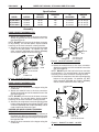
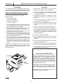
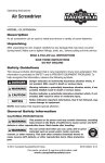
CAMPBELL
HAUSFELD
OPERATING INSTRUCTION MANUAL
SANDBLASTING KITS
MODELS AT125102AJ, AT121002AJ, AND
AT121102AJ
READ CAREFULLY BEFORE ATTEMPTING TO ASSEMBLE, INSTALL, OPERATE OR MAINTAIN THE PRODUCT
DESCRIBED. PROTECT YOURSELF AND OTHERS BY OBSERVING ALL SAFETY INFORMATION. FAILURE TO COMPLY WITH INSTRUCTIONS COULD RESULT IN PERSONAL INJURY AND/OR PROPERTY DAMAGE!
RETAIN INSTRUCTIONS FOR FUTURE REFERENCE.
7. Check hoses and air lines for weak or worn condition
before each use. Make sure all connections are
secure before use.
Description
Campbell Hausfeld sandblasting equipment is designed
for cleaning and removing rust, scale, paint, grime and
dirt for stripping, polishing and etching projects. This
equipment can be used with sand, abrasive powders,
or water and other liquids.
! WARNING !
DO NOT POINT THE SANDBLAST GUN AT ANYONE OR OBJECTS OTHER THAN THE INTENDED
WORK OBJECT.
8. Do not depress the trigger when connecting the air
supply hose.
Unpacking
After unpacking the sandblasting kit, carefully inspect
for any damage that may have occurred during transit.
Check for loose, missing or damaged parts.
! DANGER
DO NOT WORK AROUND OILY RAGS OR FLAMMABLE LIQUIDS. SAND STRIKING METAL CAN
CAUSE A SPARK AND CREATE A FIRE OR EXPLOSION.
General Safety Information
1. Read this instruction manual before installing this
device to the compressor pump.
2. Safety glasses or face shield, gloves and a respirator
must be worn during operation. Always work in a well
ventilated area.
Figure 1
Figure 2
3. During operation, do not expose the hands or skin
directly in the line of the blast nozzle.
4. After installation, inspect to make sure all components seal properly.
5. Keep children away at all times. All visitors must be
kept a safe distance and wear safety glasses, gloves
and a respirator.
6. Do not exceed the maximum operating pressure of
the sandblasting equipment (125 PSI).
! WARNING !
DO NOT SPRAY ACIDS OR CAUSTICS.
! WARNING !
DISCONNECT THE SANDBLASTER FROM THE
AIR SUPPLY BEFORE CHANGING ACCESSORIES
OR ATTEMPTING TO INSTALL, SERVICE, RELOCATE OR PERFORM ANY MAINTENANCE.
Figure 3
Copyright 1993, Campbell Hausfeld/Scott Fetzer Company
IN241900AV
__
1
__
1/93
MODELS AT125102AJ, AT121002AJ AND AT121102AJ
IN241900AV
Specifications
MODEL
NOZZLE
HOPPER
CAPACITY
MAXIMUM
PSI
HP
REQUIRED
MINIMUM
CFM
AT125102AJ
AT121002AJ
AT121102AJ
Ceramic
Ceramic
Ceramic
30 lbs
60 lbs
120 lbs
125
125
125
1 or more
2 or more
2 or more
2.2 @ 40 PSI
2.2 @ 40 PSI
2.2 @ 40 PSI
Assembly
HOSE CONNECT ASSEMBLY FOR
MODEL AT125102AJ - 30 LBS
1. Attach the material hose to the hose connector.
Attach the opposite end of the material hose to the
gun (See Figure 4).
NOTE: DO NOT cover the hole in the hose connector
for dry blasting. For use with liquids, slip the material
hose fully on the hose connector covering the hole.
2. Attach the air compressor hose to the opening at the
bottom of the gun handle. An optional 1/4" NPT
quick connector (MP2468) and coupler (MP2883)
can be used to attach the hose to the gun.
ATTACH
AIR
HOSE
MATERIAL
HOSE
CONDUIT
NUT
MATERIAL
HOSE
DO NOT
COVER
THIS HOLE FOR
DRY BLASTING
HOSE
CONNECTOR
Figure 5 _ Model AT121002AJ - 60 LBS
DO NOT COVER
THIS HOLE FOR
DRY BLASTING
ATTACH
AIR
HOSE
3. Attach the material hose to the hose connector.
Attach the opposite end of the material hose to the
gun (See Figure 6).
NOTE: DO NOT cover the hole in the hose connector
for dry blasting. For use with liquids, slip the material
hose fully on the hose connector covering the hole.
4. Attach the air compressor hose to the opening at the
bottom of the gun handle. An optional 1/4" NPT
quick connector (MP2468) and coupler (MP2883)
can be used to attach the hose to the gun.
HOSE
CONNECTOR
Figure 4 _ Model AT125102AJ - 30 LBS
HOSE CONNECT ASSEMBLY FOR
MODEL AT121002AJ - 60 LBS
PROTRUDING
HUB
1. Attach the hose connector to the hopper using the
conduit nut.
2. Attach the material hose to the hose connector.
Attach the opposite end of the material hose to the
gun (See Figure 5).
NOTE: DO NOT cover the hole in the hose connector
for dry blasting. For use with liquids, slip the material
hose fully on the hose connector covering the hole.
3. Attach the air compressor hose to the opening at the
bottom of the gun handle. An optional 1/4" NPT quick
connector (MP2468) and coupler (MP2883) can be
used to attach the hose to the gun.
WHEEL
CAP
ATTACH
AIR
HOSE
HOPPER AND HOSE CONNECT ASSEMBLY
FOR MODEL AT121102AJ - 120 LBS
1. Slide the wheel onto the axle and lightly hammer on
the wheel cap. Make sure the protruding hub on the
wheel is facing the hopper (See Figure 6). Repeat for
the opposite side.
2. Attach the hose connector to the hopper using the
conduit nut.
MATERIAL
HOSE
HOSE
CONNECTOR
CONDUIT
DO NOT NUT
COVER
THIS HOLE
FOR DRY BLASTING
Figure 6 _ Model AT121102AJ - 120 LBS
__
2 __
MODELS AT125102AJ, AT121002AJ AND AT121102AJ
IN241900AV
Installation
Operation
It is recommended that sandblasting equipment be
used with commonly available sandblast cabinets. However, a temporary sandblasting booth can also be used.
1. Always wear a safety shield or safety glasses,
gloves and a respirator when sandblasting.
2. Locate the compressor as far away as possible
from the sandblasting area to minimize the dust in
the compressor intake.
MAKING A TEMPORARY SANDBLAST BOOTH
To make a temporary sandblast booth, refer to Figure 7
and follow the outlined procedures below.
3. The higher the air pressure (maximum 125 PSI),
and the closer to the work , the quicker the job will
be done.
Material needed:
1 roll of 3" plastic tape
1 large corrugated box
4 square feet of plexiglass
1/4 yard of old cloth
4. Use a large grit abrasive to remove material and
use a small grit to smooth surfaces.
5. Always trial test the sandblaster to make sure the
job is done without damage by testing on a hidden
surface.
1. Cut a rectangular hole out of one side on the box to
serve as a window opening. Leave a least a two inch
border around the cutoff for strength.
2. Cut the plexiglass two inches wider than the cutoff
dimensions. This will be the top of the booth.
3. Cut two five inch round holes in one or two of the
other sides of the box for arm holes.
4. Cut two pieces of cloth approximately eight inches
wide to act as a curtain for the arm holes. Tape the
top of the cloth pieces to the inside of the box so that
the cloth hangs over each hole.
5. Cut a 1-1/2 inch hole in the corner of the flaps on the
open end of the box for the air and material hoses.
6. (OPTIONAL) Cut a small hole in the unopened end
of the box for inserting a hole from a shop vacuum.
This will aid in clearing dust and collecting sand for
reuse.
6. Always filter (screen) the abrasive material to remove any caked material and prevent clogging.
7. Use a compressor that can supply enough air (See
Specifications). A compressor too small will cause
air pressure to drop and the sandblaster will not
operate satisfactorily.
8. Do not try to spray heavy liquids.
9. When spraying devices such as carburetors, stuff
rags or paper into all openings to prevent internal
damage.
10. Use the lowest effective pressure on soft surfaces
to prevent pitting the surface.
11. Whenever the nozzle is removed and replaced, use
a brush to clean the threads and replace the o-ring.
To use the sandblasting booth, put the booth on a work
bench with an overhead light. Put the object to be
sandblasted and the sandblast gun into the box. Tape
the open end shut.
PLEXIGLASS
2"
12. Soap and water can be used for cleaning purposes
for automobiles, lawn chairs, etc.
MOISTURE IN COMPRESSED AIR
Moisture in compressed air will form into droplets
as the air comes from the compressor pump. When
humidity is high or when a compressor is in continuous use for an extended period of time, moisture will collect in the tank. When using a sandblast
gun, this water will be carried from the tank through
the hose and out of the gun as droplets mixed with
the material being sprayed.
2"
CLOTH
5" DIA
HOLES
FOR HANDS
IMPORTANT: THIS CONDENSATION WILL CAKE
THE SAND AND CLOG THE SANDBLASTING
GUN. A CLOGGED GUN WILL NOT OPERATE.
11/2"
A compressed air dryer and/or air line filter will help
eliminate this moisture (MP2121)
Figure 7
__
3 __
MODELS AT125102AJ, AT121002AJ AND AT121102AJ
IN241900AV
Operation
TYPE OF
ABRASIVE
(SIEVE/SIZE)
APPLICATION
Sand
(20-40)
General purpose use. Removing light rust and paint from metal, wood or other surfaces; wood
finishing; metal cleaning; glass and stone etching; hole drilling in glass; brick or cement block
cleaning; brass and silver cleaning; light brick cleaning; exterior automotive parts cleaning;
light stone and cement removal and water deposit removal.
Sand
(50-100)
Use for a fine polish finish or antique wood finish, brass and silver polishing, automotive parts
cleaning and polishing, sheet metal surface polishing, and fine glass etching.
Aluminum Oxide
Corn Cob Meal
Walnut or
Pecan Shells
(Ground)
Heavy rust removal and rough surface paint removal
Wood cleaning (fine)
Wood cleaning (coarse)
NOTE: Abrasive media that has not been cleaned and screened should be avoided, because the media could contain
material that will clog the gun.
Limited Warranty
1. DURATION: One year from the date of purchase by the original purchaser.
2. WHO GIVES THIS WARRANTY (WARRANTOR):
Campbell Hausfeld
The Scott Fetzer Company
100 Production Drive
Harrison, Ohio 45030
Telephone: (513) 367-4811
3. WHO RECEIVES THIS WARRANTY (PURCHASER): The original purchaser (other than for purposes of resale) of the Campbell Hausfeld product.
4. WHAT PRODUCTS ARE COVERED BY THIS WARRANTY: Any Campbell Hausfeld portable air compressor, air tool or supplementary air accessory
supplied or manufactured by Warrantor.
5. WHAT IS COVERED UNDER THIS WARRANTY: Defects on material and workmanship which occur within the duration of the warranty period.
6. WHAT IS NOT COVERED UNDER THIS WARRANTY:
A. Implied warranties, including those of merchantability and FITNESS FOR A PARTICULAR PURPOSE ARE LIMITED TO ONE YEAR FROM THE DATE
OF ORIGINAL PURCHASE. Some states do not allow limitations on how long an implied warranty lasts, so the above limitations may not apply to you.
B. ANY INCIDENTAL, INDIRECT, OR CONSEQUENTIAL LOSS, DAMAGE, OR EXPENSE THAT MAY RESULT FROM ANY DEFECT, FAILURE, OR
MALFUNCTION OF THE CAMPBELL HAUSFELD PRODUCT. Some states do not allow the exclusion or limitation of incidental or consequential damages,
so the above limitation or exclusion may not apply to you.
C. Any failure that results from an accident, purchaser’s abuse, neglect or failure to operate products in accordance with instructions provided in the owner’s
manual(s) supplied with product.
D. Normal adjustments which are explained in the owner’s manual(s) provided with the product.
E. Items or service that are normally required to maintain the product, i.e. lubricants.
7. RESPONSIBILITIES OF WARRANTOR UNDER THIS WARRANTY: Repair or replace, at Warrantor’s option, products or components which have failed
within duration of the warranty period.
8. RESPONSIBILITIES OF PURCHASER UNDER THIS WARRANTY:
A. Deliver or ship the Campbell Hausfeld product or component to the nearest Campbell Hausfeld Authorized Service Center. Freight costs, if any, must
be borne by the purchaser.
B. Use reasonable care in the operation and maintenance of the products as described in the owner’s manual(s).
9. WHEN WARRANTOR WILL PERFORM REPAIR OR REPLACEMENT UNDER THIS WARRANTY:
A. Repair or replacement will be scheduled and serviced according to the normal work flow at the servicing location, and depending on the availability of
replacement parts.
B. If the purchaser does not receive satisfactory results from the Authorized Service Center, the purchaser should contact the Campbell Hausfeld Product
Service Department (see paragraph 2).
This Limited Warranty gives you specific legal rights and you may also have other rights which vary from state to state.
Printed in Taiwan
__
4 __
MODELS AT125102AJ, AT121002AJ AND AT121102AJ
IN241900AV
Suggested Uses
TYPE OF
ABRASIVE
(SIEVE/SIZE)
APPLICATION
DISTANCE
FROM
WORK
PSI
Sand
(30-50)
Glass Beads
Etching and
Drilling Holes in
Glass
1-4"
40-90
Sand (40)
Ground
Walnut
Shells
Antiquing
or Weathering
Wood
2-6"
40-90
1-6"
40-70
Sand (50-100) Wood Sanding
Glass Beads and Refinishing
Ground Walnut
Furniture
Shells
SUGGESTIONS
Move gun back and forth over the template in a
brushing manner. Blast at a 90° angle. For fine polishing, use glass beads for the abrasive. For drilling
holes, use 30 sieve sand
Use brushing strokes and watch the abrasion rate
carefully. Soft wood will wear faster than hardwood.
Smaller grit sizes give a smoother finish. Start with low
pressure and gradually build up pressure. Blast at a
45° angle
Use brushing strokes and watch the abrasion rate
carefully. Use walnut shells for coarse finishing and
glass beads or fine sand for fine finishing. Blast at a
45° angle
Sand (20-40)
Cleaning
Barbecue Grills
and Iron Pots
1-4"
50-125
Use larger grit sand on a hidden area. If the base
material is being damaged, use a smaller grit. Blast
at a 80-90° angle
Sand (20-40)
Aluminum
Oxide
Cleaning
Automotive
Parts
1-4"
40-80
Be sure to mask any glass or painted surface that
could be accidentally damaged. Blast at a 80-90°
angle
Sand (20-40)
Cleaning
and Stripping
Masonry
1-4"
50-125
Ground Pecan
or Walnut
Shells & Corn
Cob Meal
Cleaning or
Preparing for
Paint
1-6"
40-125
Sand (20-50)
Aluminum
Oxide (50-80)
Cleaning,
Stripping
Outdoor
Equipment
1-3"
50-125
Technical Service
For information regarding the operation or repair
of this product, please call 1-800-543-6400 between 8 a.m. and noon or between 1 p.m. and 5
p.m. (EST), Monday through Friday for assistance. If you are calling from Ohio or outside the
continental United States, please call collect, 1513-367-1182.
Use a heavy grit sand with a sweeping overlapping
stroke. Blast at a 80-90° angle
Use brushing strokes and watch the abrasion rate
carefully. Soft wood will wear faster than hard wood.
Smaller grit sizes give a smoother finish. Start with
low pressure and gradually build up pressure. Blast at
a 45-60° angle
Remove flaking paint first with wire brush, then sandblast with a heavy grit abrasive. Multiple layers of old
paint should be scraped first. Prime immediately
following sandblasting to prevent corrosion. Blast at
a 45-60° angle
Please provide following
information:
• Model Number
• Serial Number (if any)
• Part Description and Number
as shown in Parts List.
__
5 __
Address parts correspondence
to:
Campbell Hausfeld
100 Production Drive
Harrison, Ohio 45030
IN241900AV
MODELS AT125102AJ, AT121002AJ AND AT121102AJ
Troubleshooting Chart
SYMPTOM
POSSIBLE CAUSE(S)
CORRECTIVE ACTION
Low or no air pressure
1. Regulator set incorrectly
2. Pinched hose
3. Dirty compressor filter
1. Reset regulator
2. Straighten hose
3. Clean or replace filter
Material not blasting from
gun
Clogged material hose
Lower the pressure below 40 PSI.
Firmly hold the gun tip flat against the
ground and pull the trigger to force
the material back out of the material
hose
Clogged gun
1. Damp or heavy material
1. Replace with dry abrasive.(Damp
material can be dried and reused).
2. Water in air supply
2. Drain air tank and install air filter.
See "Moisture in Compressed Air"
box
Gun will not shut off – trigger stuck
Damaged o-rings
Remove and replace o-rings
Sputtering – low vacuum
1. Worn jet and/or nozzle
2. Abrasive buildup around
jet/nozzle
1. Replace jet and/or nozzle
2. Remove nozzle and jet and clean.
Make sure the threads are clean
before replacing
Sputtering – air/abrasive
leaks at nozzle/jet area
1. Loose nozzle or jet
2. Damaged o-ring
1. Tighten nozzle or jet
2. Replace o-ring
Sputtering – vacuum leak
1. Loose material hose
2. Damaged o-ring
1. Tighten material hose
2. Replace o-ring
Sputtering – particle
clogging
Hose connector hole is covered
Uncover hose connector hole
__
6 __
IN241900AV
MODELS AT125102AJ, AT121002AJ AND AT121102AJ
Service Notes
__
7 __
IN241900AV
MODELS AT125102AJ, AT121002AJ AND AT121102AJ
Service Notes
__
8 __