1
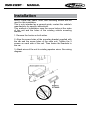
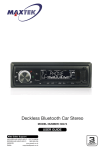
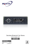
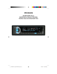
RMD 2 1 2BT
manual
• GB •
RMD 212BT MANUAL
Contents
Warnings Before Installation...................................................3-5
Before You Install.......................................................................6
Installation (DIN Front Mount).....................................................7
Installation (Vehicle's Brackets)..................................................8
Wiring Connections...............................................................9
Control of the Unit..................................................................10
Bluetooth Operation..............................................................11
Basic Operation.....................................................................1
Radio Operation.....................................................................13
RDS Operation.................................................................14
USB/SD Operation.................................................................15
Simple Troubleshooting Guide................................................16
Specifications..........................................................................16
Welcome!
Thank you for purchasing this high-technology car stereo with
USB, SD/MMC control. This unit can encode and record songs
and radio programmes to your USB Flash disk or SD/MMC
card. If there is any compatibility problems, we recommend you
to format your flashdisk/storage card in FAT3 mode before
using it. If the problem persisits, kindly consult your dealer for
assistance.
Owner’s Manual
RMD 212BT MANUAL
Warnings Before Installation
Important Warnings to Take Note of BEFORE Commencing Installation
Damage Caused By Incorrect Installation or Usage is
NOT Covered By Warranty. PLEASE Take The Time To
Read The Installation Notes Carefully.
To Validate The Warranty Please Ensure That The Unit
Is Installed By A Professional, VAT Registered Car Audio Installation Company.
• To avoid shorts in your vehicles electrical system, be sure
to disconnect the battery cable before beginning installation.
• This unit is intended for vehicles with a 1-volt battery and
negative grounding. Before installing the unit in a recreational
vehicle, truck, or bus, check that the battery voltage is 1 volts.
• Remove the two transport screws from the top of the unit
before installation.
• The black lead is ground. A good chassis ground requires a
tight connection to ground. The area should be free from rust,
paint or any form of dirt. Please ground this lead separately
from the ground of high-current products such as power amps.
If you ground the products together and the ground becomes
detached, there is a risk of damage to the products or fire.
• Be sure to connect the colour coded leads according to the diagram. Incorrect connections may cause the unit to malfunction
or damage the vehicle’s electrical system. Cords for this product
and those for other products may be different colours even if they
have the same function. When connecting this product to another product, refer to the supplied installation manuals of both
products and connect cords that have the same function.
• Be sure to connect the negative (-) speaker leads to the negative (-) speaker terminal. Never connect the negative (-) speaker
leads to chassis ground.
• The unit is only designed for use with 4 speakers. Do not combine outputs for use with speakers. Do not ground negative
speaker leads to the chassis ground.
• Speakers connected to this unit must be high-power units with
a minimum rating of 45W and impedance of 4 to 8 ohms. Connecting speakers with output and/or impedance values other
than those noted here will result in damage to the head unit
Owner’s Manual 3
RMD 212BT • MANUAL
Warnings Before Installation
and the speakers. Check the condition of your speakers carefully- connecting this unit to old or degraded speakers may result in a fault which will damage the audio IC and invalidate the
warranty.
• If this unit is installed in a vehicle that does not have an ACC
(accessory) position on the ignition switch, the red lead of the
unit should be connected to a terminal coupled with ignition
switch ON/Off operations. If this is not done, the vehicle battery
may be drained when you are away from the vehicle for several
hours.
• Secure the wiring with cable clamps or adhesive tape. To protect the wiring, wrap adhesive tape around them where they lie
against metal parts. To avoid short-circuiting, cover all disconnected lead with insulating tape. There is a possibility of shortcircuiting if the leads are not insulated.
• Route and secure all wiring so it cannot touch any moving
parts, such as the gear lever and handbrake. Do not route wiring in places that get hot, such as near the heater outlet. If the
insulation of the wiring melts or gets torn, there is a danger of
the wiring short-circuiting to the vehicle’s body.
• Don’t pass the yellow lead through a hole into the engine compartment to connect to the battery. This will damage the lead’s
insulation and cause a very dangerous short.
• Do not shorten any leads. If you do, the protection circuit may
fail to work when it should.
• Never feed power to other equipment by cutting the insulation
of the power supply lead of the unit and tapping into the lead.
The current capacity of the lead will be exceeded, causing overheating.
• Since a unique audio I/C circuit is employed, never wire so
the speaker leads are directly grounded or the left and right
– speaker leads are common.
• When this product’s source is switched ON, a control signal
is outputted through the orange lead. Connect to an external
power amp’s system remote control or the car’s Auto-antenna
relay control terminal (max. 300mA 1 V DC). If the car features
a glass antenna, connect to the antenna booster power supply
terminal.
• When an external power amp is being used with this system,
do not connect the orange lead to the amp’s power terminal.
Likewise, do not connect the orange lead to the power terminal
of the auto-antenna. Such connection could cause excessive current
drain and a major malfunction. Refer to the relevant owner’s manual
4
Owner’s Manual
RMD 212BT • MANUAL
Warnings Before Installation
•
•
•
•
•
•
•
for details on connecting the power amp and other units, then make
the connections correctly.
Do not block any vents or heater panels. Blocking them will cause
heat to build up and may result in fire.
Make sure that the unit has a good chassis ground. A good ground
connection will eliminate most electrical noise. A good chassis
ground requires a tight connection to the vehicles metal chassis.
The area around the ground connection should be clean, bare metal
without rust, paint, plastic or dirt for a good electrical connection.
If noise is still experienced when the motor of the vehicle accelerates, a choke should be placed in line with the power to the unit. The
installation company will know what is required.
When replacing the fuse(s) the replacement must be of the same
amperage as shown on the fuse holder. Never replace a fuse with
another of a different value. If the fuse blows again please contact
your installation company.
Do not block vents or heater panels. Blocking them will cause heat
to build up inside and may result in fire.
Double check that all wiring and connections are correct before reconnecting the battery and turning on the unit.
After completing the installation and before operating the unit, reconnect the battery, Then press the (RES) button with a pointed object,
such as a ball-point pen to set the unit to its initial status. After pushing the button, wait a few seconds for the red light to flash.
Tools for Installation
• removel wrenches are supplied for taking out the old unit and place
with this brand name car radio. The following tools and supplies may
also be needed for the installation:
Tools for Installation:
- Philips Screw-drivers
- Wire Stripper
- Wire Cutter
- Hammer
- Pencil
- Electrical Tape
- Electric Drill
Supplies for Installation:
- Machine Screws
- Crimp Connectors
- 14 Gauge Wire for Power
Connections
- 14-16 Gauge Speaker Wires
* The above are not supplied.
Owner’s Manual 5
RMD 212BT • MANUAL
Before You Install
Automotive audio equipment installations can be troublesome at
times, even to the most experienced of installation technicians.
If you are not confident working with electrical wiring, removing
and reinstalling interior panels, carpeting, dashboards or other
components of your vehicle, please call your dealer in order to
have the unit professionally installed.
IMPORTANT: Remove the two transport screws from the top of
the unit before installing.
1. Remove the Old Unit from the Dashboard
1. Remove the outer trim frame.
DIN Front Mount
. Insert the keys supplied with the
old unit into both sides of the unit
as shown in figure below until
they click. Pull to remove the old
unit from the dashboard.
DO NOT DISCONNECT WIRES
AT THIS TIME!
2. Mark Polarity of the Speaker Wires
Marking the polarity of the speaker wires will make it easier to
connect the existing speakers to your car radio.Consult wiring
diagram of existing head unit before disconnecting any wires. If
you are not positive of the polarity of the existing wires from
the speakers to the head unit, install new wires.
1. While the old unit is playing,
disconnect the wires from
one speaker
. Take a length of masking
tape and fold it around the
wire so it forms a flag.
3. On the masking tape mark
the polarity of the speaker
wires (+ & - ), as well as left
or right, and front or rear.
6
Owner’s Manual
4. Double check that you
marked the first speaker
correctly by checking that
the speaker wires are the
same at the head unit.
5. Repeat this procedure for
all of the speakers.
6. Mark the power, ground,
and any other wires also.
RMD 212BT • MANUAL
Installation
WARNING!
Disconnect negative battery terminal from battery
before starting installation. Consult the vehicle’s
owner’s manual for proper instructions.
NOTE: Mark the polarity of the existing speaker wires before
disconnecting battery.
NOTE: Remove the two transport screws from the top of the
unit before installing.
DIN Front Mount
1. After removing the old
radio and mounting sleeve,
insert
supplied
mounting sleeve into opening.
3. Attach wires from the unit to
existing wires. See wiring connections diagram. Insert radio
into dashboard. Then apply the
trim frame to outside of radio.
2. Bend the tabs on the mounting sleeve to keep the mounting sleeve firmly in place.
4. Support radio using supplied rear mounting bolt
and steel bar. See parts list.
Owner’s Manual 7
RMD 212BT • MANUAL
Installation
NOTE: Outer trim frame, hook, and mounting sleeve are not
used for this installation.
This is only intended as a general guide; contact the vehicle's
manufacturer for specific instructions.
This method of installation uses the screw holes at the sides
of the unit and the holes of the existing vehicle mounting
bracket.
1. Remove the hooks on both sides.
. Align the screw holes of the mounting bracket supplied with
the car and the screw holes of the main unit. Tighten the screws on each side of the unit. Then fasten the brackets to
the car.
3. Attach wires of the unit to existing speaker wires. See wiring
diagram.
8
Owner’s Manual
RMD 212BT • MANUAL
Wiring Connections
Make sure that you have a good chassis ground. Good ground
connections will eliminate most electrical noise problems. A
good chassis ground requires a tight connection to the vehicle's metal chassis. The area around the ground connection
should be clean, bare metal without rust, paint, plastic, dust,
or dirt for a good electrical connection.
MIC AFTER
Front Right Speaker,Grey +
Rear Right Speaker,Blue +
Front Left Speaker,Green +
Orange Power Antenna
ACC(IGN)
Rear Left Speaker,Brown +
B
A
Yellow Memory +
Rear Right Speaker,Blue /White -
Front Right Speaker,Grey / White -
Black Ground
Rear Left Speaker,Brown / White -
Front Left Speaker,Green / White -
Speaker Wiring Notes
Follow the above wiring diagram to install the head unit
with new or existing speakers.
• This unit is designed for use
with four (4) speakers with an
impedance between 4 Ohms
to 8 Ohms.
• An impedance load of less
than 4 Ohms could damage
the unit.
• Never bridge or combine the
speaker wire outputs. When
not using four speakers, use
electrical tape to tape the
ends of the unused speaker
outputs to prevent a short
circuit.
• Never ground the negative
speaker terminals to chassis
ground.
Owner’s Manual 9
RMD 212BT • MANUAL
Controls of the Unit
20
1. Power on / off / Mute
. Mode Select / TA / Answer Button
3. Sound Select / Volume +/4. LCD Screen
5. Release Panel Button
6. Previous Track / Backward Button
7. Band Switch / PTY
8. Next Track / Fast Forward Button
9. Auto Preset Scan / Reject Button
10. Number 1 / Play / Pause
10 Owner’s Manual
11. Number / Introduction
1. Number 3 / Repeat
13. Number 4 / Random
14. Number 5 / Folder Down
15. Number 6 / Folder Up
16. Aux input Jack
17. USB Slot
18. MIC Receiver
19. SD Card Slot
0. Reset Button
RMD 212BT • MANUAL
Bluetooth Operation
1. Pairing
Press and hold the BAND/ID3/TEL
button until the word “BT PAIR” blinks
on the display waiting for the bluetooth device to connect.
At this blinking time, please run the
bluetooth search and connect function
in your cellphone. The car radio model no “BT car stereo” will be shown on
the cellphone. Select this car radio
and connect. When you are asked
for a connection password, please input “0000” in your cellphone to finish
the pairing. The bluetooth icon on the
display will be on indicating that the
connection is established. Bluetooth
function is ready to use.
2. Calling
In any play mode, dial the desired
number on your cellphone. The unit
will switch to bluetooth handsfree
mode automatically. “CALL OUT” will
be shown on the display indicating the
dialling is in progress.
“ANSWER” button is pressed. Rotate
the volume knob during ringing or
conversation to adjust the respective
volume level.
4. Rejecting Calls
During ringing or conversation, press
the “EJECT” button to end the call or
reject the call. “END CALL” will be
shown on the display and the unit will
resume to the original play mode.
5. BT Audio (A2DP)
Press MOD/(with green phone logo)
button until the unit entered BT MUSIC. BT audio will play automatically
when you play the song in the cellphone. You could pause by “ ” button, to choose previous or next song
by pressing |<< and >>| button.
6. Disconnecting
Disconnect the paired phone by operating on the cellphone. You cannot
process disconnection on the car radio headunit.
3. Accepting Calls
When there is incoming call, “CALL
IN” will be shown on the display indicating there is phone call to answer.
“BT TALK” will be shown after the
Owner’s Manual 11
RMD 212BT • MANUAL
Basic Operation
1. Tuning the unit On / Off
Press POWER button to turn the unit
on. Press again to turn the unit off.
the front & rear speakers. When “F=R”
is shown on the screen, it indicates
that the fader is 0.
2. Mode Selection
Press the MODE button to cycle
through different play modes.
10. Preset Equalizer Function
Press SEL Button until the display
shows “EQ” ,then use button to
choose the EQ sound effects. The
Sequence of equalizer setting will be
as follows:
FLAT-ROCK-POP-CLASS
3. Loudness Control
Press the SEL Button repeatly until the display shows “LOUD ON” or
“LOUD OFF”. Rotate the VOL button
to adjust. When “LOUD ON” shown
on the display indicates that loudness
function is on.
4. Mute Control
Press the MUTE Button to activate
the Mute function. Press the button
again to cancel.
5. Volume
Rotate the VOL Button to adjust the
volume level. Turn the button clockwise to increase the volume, and vice
versa. The larger the number of volume, the higher the volume level.
6. Bass
Press the SEL Button repeatly until
the display shows “BAS”. Rotate the
VOL button to adjust. When DSP is
ON, bass control is not available.
7. Treble
Press SEL Button repeatly until the
display shows “TRE”. Rotate the VOL
Button to adjust. When DSP is ON,
treble control is not available.
8. Balance
Press SEL Button repeatly until the
display shows “BAL”, then Rotate the
VOL Button to adjust the balance between the left & right speakers. When
“L=R” is shown on the screen, it indicates that the balance is 0.
9. Fader
Press SEL Button repeatly until the
display shows “FAD”, Rotate the VOL
Button to adjust the balance between
1 Owner’s Manual
11. Beep Function
Press SEL button repeatly until the
“BEEP” shown on the screen. Rotate
the VOL Button to choose “BEEP
OFF” or “BEEP ON”. “BEEP OFF”
means Beep function is inactive.
“BEEP ON” means beep sound will be
heard when any button pressed.
12. Preset Volume
Press and hold the SEL Button for
seconds, the “TA ALLARM” will be
shown on the screen. Press the SEL
Button repeatly until the “P-VOL”
shown on the screen. Rotate the VOL
Button to choose the volume level
which will be kept as preset when the
unit is turned on.
13. Clock
Press and hold CLK Button, the clock
will show on the display.
Then press and hold the button until
the hours blinks on the display, rotate
the SEL knob to set hours, then press
the SEL Button until the minutes blinks
and rotate the SEL knob to set. Press
the CLK Button to confirm.
RMD 212BT • MANUAL
Radio Operation
1. Choose Radio Band
Press the BND Button anytime to access the radio function.
The unit comes with five bands- three
FM Bands (FM1, FM, and FM3) and
two AM Bands (AM1, and AM). Each
of the five bands can store up to six
preset stations, for a total of 30 preset
memory stations.
2. Radio Tune / Seek Function
In Radio Mode, turn the “>>| ” or “|<<“
once, the radio frequency will proceed
by one step.
Press and hold the SEEK |<< or >>|
Button for seconds and the radio
will seek the next strong and clear frequency station. Repeat to seek more
stations in your listening area with a
strong signal.
3. Mono / Stereo Reception Control
In FM radio mode, Press SEL Button repeatly until the display shows
‘MONO’ or “STEREO”. Roate the Vol
button to choose the reception control, the word “MONO” shown on the
screen indicating the mono reception
is received.
4. Save Your Preset Stations
There are six numbered preset buttons which can store and recall stations for each band. While listening to
a radio station you would like to save
as a pre-set, press and hold one of
the buttons numbered 1-6 until the
preset station number is shown. The
button you pressed is now the pre-set
button for that station.
B. Scan Saved Stations
Press the F/PS button once to perform the scanning functions. In FM
mode, press the F/PS button and
the stations in that FM band will
be scanned; press the button in AM
mode and scan the band stations of
that AM Band.
6. Local / DX
Press SEL Button repeatly until the
display shown “LOC”. Rotate the VOL
button to choose “LOC ON“ or “LOC
OFF”.
a. “LOC ON” showing on the display,
means local reception is turned on;
b. “LOC OFF” showing on the display,
means distant reception is turned on.
Local and distance reception setting can facilitate the radio reception,
depending on the location in which
the radio is being used.
7. Reseting The Unit
When the unit is off, press and hold
MOD+BND button for 3 seconds. The
unit will reset itself and all the previous saved radio stations will be
cleared.
5. Automatic Store / Preset Scan
A. Automatic Scan & Store
While listening to the FM Radio, press
and hold the F/PS Button for 3 seconds. The receiver will automatically
scan and save the station listening
to.
While listening to the AM Radio, press
and the F/PS Button for 3 seconds.
The receiver will automatically scan
and save the station you are listening to.
Owner’s Manual 13
RMD 212BT • MANUAL
RDS Operation
1. AF-ALTERNATIVE FREQUENCY
4. MASK DPI - MASK ALL
Press and hold the volume button so
that the unit will choose the strongest
FM signal for the selected station, so
that you do not have to re-tune the
stations when driving between different transmitter coverage areas. When
AF is on, it means RDS information
is received; when AF is flashing, it
means RDS information is not yet received.
Press the sound select button for seconds, the display will show TA
SEEK. Press the sound select button
again so that the unit will show MASK
DPI. Rotate the encoder volume to
toggle between MASK DPI and MASK
ALL mode. Then leave the unit idle for
the mode to take effect. During MASK
DPI mode, the unit will mask only
the AF which has different PI, this is
the default mode; during MASK ALL
mode, the unit will mask the AF which
has different PI and no RDS signal
with high field strength.
2. TA - TRAFFIC ANOUNCEMENT
Press and hold the TA button so that
the unit will be activated for reception
of traffic announcement from local radio stations.
To choose the TA mode, press the
sound select button for seconds, the
display will show TA SEEK. Rotate
the encoder volume to choose between the TA SEEK and TA ALARM,
after chooisng, please leave the unit
idle for the mode to activate. In TA
SEEK mode, the unit will seek for traffic announcement programme when
TA is pressed; in TA ALARM mode,
no TA/TP is displayed and the alarm
is set off.
3. PTY - PROGRAMME TYPE
This radio will allow you to select the
type of programme required, and will
search for a station broadcasting that
type of programme. Press and hold
the PTY button once to show the
music type. Then press 1-6 button
to choose the different music types
available.
Press the PTY button twice to show the
speech type programme. Then press
1-6 button to choose the different
speech type programme. Each number keye will show 3 different speech
programme for you to choose.
14 Owner’s Manual
5. RETUNE S/L - SHORT/LONG
This function is to set the initial duration of automatic TA Search -- Press
and hold the sound select button until
“TA SEEK” is shown on the LCD, then
press the SEL button to cycle through
the menu selections until “RETUNE_
S” is shown, use the VOL +/- button to
choose “RETUNE_S” or “RETUNE_
L”. The default is “RETUNE_S”.
RDS Operation
RDS-EON CONTROL
This unit is equipped with the latest
technology of EON control, so that
when you are listening to Radio or CD,
if there is any travel announcemnet
from a nearby local station, the radio
will already know the frequency of
that radio station. Then it will receive
the station, turn up the volume, or
interrupt the playback of the music
for the duration of the announcement.
At the end of the announcement the
radio will return to its previous state
ready for the next announcement.
RMD 212BT • MANUAL
USB/SD Operation
1. Play MP3 / WMA from USB/SD
Plug the USB or SD card into the
USB/SD port. The MP3 and WMA
files in the USB or SD card will be
played automatically. If there is no
MP3 or WMA files in the USB or SD
card, “USB PLAY” or “SD/MMC” will
be shown on the screen.
2. Play Mode
The USB or SD/MMC mode can be
chosen by pressing the MODE button.
The “USB PLAY” means it is in USB
play mode, while “SD/MMC” means it
is in SD play mode.
3. Track / Folder Search
a. Press >>| button once to advance
one track, Press |<< button once to
go back one track.
b. Press F/PS button once, the track
number will be blink on the screen.
Rotate the VOL button to select the
track number in this fold. Press SEL
button to confirm the selection.
4. ID3
The name of the song will be displayed automatically on the screen.
5. Play / pause
When the card/ USB device has been
already loaded the playback of the
first track starts automatically. Press
the “1 PAU” button and the “PAUSE”
will be twinkled on the screen.
6. Introduction
Press the “ INT” button to select the
previous part of each song in the card
/ USB to play. The “INT + Track no.”
will be shown on the screen, indicating each song will be played for 10
seconds. After the ending of one song,
the consequent song will be played
for 10 seconds and so on. Press the
“ INT” button to cancel.
7. Repeat
Press the “3 RPT” button to repeat
the same song continuously. The
“RPT+ Track no.” will be shown on the
screen, indicating the repeatprocess
is operating. Press “3 RPT” button to
cancel.
8. Random
Press the “4 RDM” button to play all
the files in card/ USB in random order.
The “RDM + Track no.” will be shown
on the screen, indicating the songs
are arranged in random order. Press
“4 RDM” button to cancel.
9. Folder Down
Press the “ 5 - ” button once to go
back one folder.
10. Folder UP
Press the “6 + ” button once to advance one folder.
AUX IN,
RCA OUT,
1. Auxiliary Input
The Auxiliary Input Jack is on the front
panel. Insert the AUX IN cable's stereo plug into the AUX IN jack on the
panel of the unit. Route the other end
of the stereo plug to the headphone
jack of any external audio device such
as walkman and discman. Press the
Mode button to choose AUX. Connect
any portable audio device such as a
DVD player or VCD player to the AUX
IN cable. Use the volume control to
adjust volume.
2. RCA Output
The RCA Output Jack is on the back
of the unit. (Refer to Wiring) This output is for connecting amplifier, equalizer, or other audio componement that
requires a pre-amp out connection.
(Red = Right, White = Left) Follow
the manufacturers instructions for the
audio component that you are connecting.
Owner’s Manual 15
RMD 212BT • MANUAL
Simple Troubleshooting Guide
PROBLEM
CAUSE/SOLUTION
No Power
Check wiring connections.
Check and make sure the fuse is not
blown.
Replace with the proper rating/size
fuse.
Some errors occur in the LCD or
nothing functions when buttons
are pressed.
Press the RESET Button .
Unable to receive stations
Check and make sure the antenna
is connected properly.
Poor radio reception
Check and make sure the antenna
is the correct length. Make sure the
antenna is not broken. If the antenna
is broken, replace it. The antenna is
poorly grounded. Check and make sure
the antenna is grounded at mounting
location.
File information shows in LCD but
will not play.
If you have files with Digital Rights
Management(DRM). Contact the vendor
for proper use.
Specifications
GENERAL
Operating Power..................................................1 Volts DC, Negative Ground
Output Wiring...........................................Designed for using four speakers only
RCA line out..............................................................low-level outputs - 1000MV
Output Impedance..........................................Compatible 4 to 8 Ohm Speakers
Fuses.......................................................................................................10 amp
Dimensions................................................178mm(W) x 78mm(D) x 51mm (H)
Weight.....................................................................................................0.65 Kg
FM TUNER
Tuning Range...............................................................................87.5 - 108 MHz
FM Sensitivity.............................................................................................1dBu
Stereo Separation @ 1 Khz.........................................................................35dB
AM TUNER
Tuning Range................................................................................5-160 KHz
AM Sensitivity............................................................................................30dBu
16 Owner’s Manual
WWW.CALIBER.NL
Caliber Head Office • The Netherlands • Fax: +31 (0)416 69 90 01 • E-mail: [email protected]