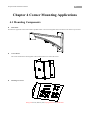
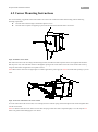
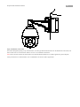
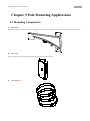
1
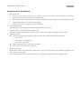
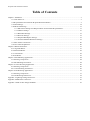
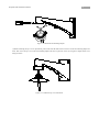
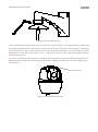
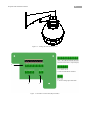
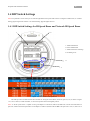
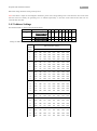
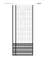
IR Speed Dome Installation Manual V2.0.0 IR Speed Dome Installation Manual 1 Thank you for purchasing our product. If there are any questions, or requests, please do not hesitate to contact the dealer. This manual applies to IR Speed Dome . This manual may contain several technical incorrect places or printing errors, and the content is subject to change without notice. The updates will be added to the new version of this manual. We will readily improve or update the products or procedures described in the manual. DISCLAIMER STATEMENT “Underwriters Laboratories Inc. (“UL”) has not tested the performance or reliability of the security or signaling aspects of this product. UL has only tested for fire, shock or casualty hazards as outlined in UL’s Standard(s) for Safety, UL60950-1. UL Certification does not cover the performance or reliability of the security or signaling aspects of this product. UL MAKES NO REPRESENTATIONS, WARRANTIES OR CERTIFICATIONS WHATSOEVER REGARDING THE PERFORMANCE OR RELIABILITY OF ANY SECURITY OR SIGNALING RELATED FUNCTIONS OF THIS PRODUCT.” 2 IR Speed Dome Installation Manual Safety Instruction These instructions are intended to ensure that the user can use the product correctly to avoid danger or property loss. The precaution measure is divided into ‘Warnings’ and ‘Cautions’: Warnings: Serious injury or death may be caused if any of these warnings are neglected. Cautions: Injury or equipment damage may be caused if any of these cautions are neglected. Warnings Follow these safeguards to prevent serious Cautions Follow these precautions to prevent potential injury or death. injury or material damage. Warnings 1. In the use of the product, you must strictly comply with the electrical safety regulations of the nation and region. 2. Please use the power adapter which is provided by normal company. The adapter should be either AC 24V/3A or DC 12V/5A according to different dome models. 3. Do not connect several devices to one power adapter as an adapter overload may cause over-heating and can be a fire hazard. 4. Please make sure that the power has been disconnected before you wire, install or dismantle the speed dome. 5. When the product is installed on a wall or ceiling, the device should be firmly fixed. 6. If smoke, odor, or noise rise from the device, turn off the power at once and unplug the power cable, then contact the service center. 7. If the product does not work properly, please contact your dealer or the nearest service center. Never attempt to disassemble the camera yourself. (We shall not assume any responsibility for problems caused by unauthorized repair or maintenance.) Cautions 1. Do not drop the dome or subject it to physical shock, and do not expose it to high electromagnetism radiation. Avoid the equipment installation on vibrations surface or places subject to shock (ignorance can cause equipment damage). 2. Do not place the dome in extremely hot, cold (the operating temperature shall be -30°C ~ +65°C), dusty or damp locations, or fire or electrical shock will occur otherwise. 3. The dome cover for indoor use shall be kept from rain and moisture. 4. Exposing the equipment to direct sun light, low ventilation or heat source such as heater or radiator is forbidden (ignorance can cause fire danger). 5. Do not aim the camera at the sun or extra bright places. A blooming or smear may occur otherwise (which is not a malfunction however), and affecting the endurance of CCD at the same time. 6. Please use the provided glove when open up the dome cover, avoid direct contact with the dome cover, because the acidic sweat of the fingers may erode the surface coating of the dome cover. 7. Please use a soft and dry cloth when clean inside and outside surfaces of the dome cover, not to use alkaline detergents. 8. Do not stare at infrared lights closely to avoid hurting your eyes when the infrared lights are on. 9. Improper use or replacement of the battery may result in hazard of explosion. Replace with the same or equivalent type only. Dispose of used batteries according to the instructions provided by the battery manufacturer. IR Speed Dome Installation Manual 3 Preparation for Installation 1. Basic requirements 1) All the electronic operation should be strict compliance with the local electrical safety regulations, fire prevention regulations and other related regulations at the installation place. 2) Check whether all the accessories are there according to the packing list, make sure that the place and installation mode are conform to the demands, if not, please contact the supplier. 3) 2. Please use this product according to the working environment. Check installation space. Make sure the place have enough space to install the speed domes and its accessories. 3. Check the intensity of conformation at the installation scene. Please make sure that the endure ability of ceilings or walls is 4 times as the weight of speed dome and its accessories. 4. Preparation of cables 5. Choose the video cable according to the transmission length. The video should meet the least demands as: 1. 75Ω resistance 2. 100% copper core conducting wire. 3. 95% weaving copper shield. RS485 communication cable, please refer to Appendix 2 24V AC power cable, please refer to Appendix 3 Please keep all wrappers Please keep all wrappers after unpack them for future use. In case of any failure occurred, please return the speed dome to the factory with the original wrapper. Note: Transportation without the original wrapper may result in damage on the speed dome and cost additional charge. 4 IR Speed Dome Installation Manual Table of Contents Chapter 1 Installation ................................................................................................................................................... 5 1.1 Check Parts List ............................................................................................................................................. 5 1.2 IR Speed Dome and Network IR Speed Dome Installation ........................................................................... 5 1.3 Initial Settings .............................................................................................................................................. 14 1.4 DIP Switch Settings ..................................................................................................................................... 15 1.4.1 DIP Switch Settings for IR Speed Dome and Network IR Speed Dome .......................................... 15 1.4.2 Address Settings................................................................................................................................ 16 1.4.3 Baud Rate Settings ............................................................................................................................ 19 1.4.4 Protocol Settings ............................................................................................................................... 19 1.4.5 Simplex/Half-duplex Settings ........................................................................................................... 19 1.4.6 Terminal Matched Resistance Settings ............................................................................................. 19 1.5 Alarm In/Out Connections ........................................................................................................................... 20 1.6 Power Cable Explanation............................................................................................................................. 20 Chapter 2 Mounts Dimension .................................................................................................................................... 21 2.1 Long Wall Mount ......................................................................................................................................... 21 2.2 Short Wall Mount ......................................................................................................................................... 22 2.3 Corner Mount............................................................................................................................................... 22 2.4 Pole Mount................................................................................................................................................... 23 Chapter 3 Wall Mounting Applications ..................................................................................................................... 24 3.1 Mounting Components ................................................................................................................................ 24 3.2 Wall Mounting Instructions ......................................................................................................................... 24 Chapter 4 Corner Mounting Applications .................................................................................................................. 28 4.1 Mounting Components ................................................................................................................................ 28 4.2 Corner Mounting Instructions ...................................................................................................................... 29 Chapter 5 Pole Mounting Applications ...................................................................................................................... 31 5.1 Mounting Components ................................................................................................................................ 31 5.2 Pole Mounting Instructions .......................................................................................................................... 32 Appendix 1 Lightning & Surge Protection ................................................................................................................ 35 Appendix 2 RS485 Bus Connection .......................................................................................................................... 36 Appendix 3 Table of Wire Gauge Standards .............................................................................................................. 39 5 IR Speed Dome Installation Manual Chapter 1 Installation 1.1 Check Parts List Prior to installation, unpack the dome unit and check whether it is in good condition and all parts and accessories are included by referring to the packing list. Note: The power supply for the speed dome is AC24V/3A. 1.2 IR Speed Dome and Network IR Speed Dome Installation Note: The following installation instructions are applicable to IR speed dome, network IR speed dome and network high-definition IR speed dome models. 1. Install the dome mount. Please refer to the related sections from Chapter2 to Chapter5 for specific installation methods of different mounts. 2. Taking the wall mounting application for example, mount the fast mounting adapter and top cover of the IR speed dome to the wall mount. Pass the integrated cable through the wall mount firstly and then through the top cover. (1) The fast mounting adapter is shown below: Lock screw Figure 1.2.1 Fast mounting adapter (2) Wrap the thread compound to the thread of fast mounting adapter and screw the thread into the wall mount. Then, wedge the set screw to the wall mount as shown in figure 1.2.2. 6 IR Speed Dome Installation Manual Figure 1.2.2 Install the fast mounting adapter (3) Before installing the top cover of speed dome, please make sure that both of the lock screws on the fast mounting adapter are slack. Then screw the top cover to the fast mounting adapter and screw up the lock screws by using the L shaped socket screw hexagon wrench. Figure 1.2.3 Install the top cover of the dome 7 IR Speed Dome Installation Manual Figure 1.2.4 Screw up the lock screws 3. Take out the speed dome and tear off the protective sticker from it, as shown in figure 1.2.5. Configure the address, baud rate and other parameters through DIP switch SW1 and SW2 located on the bottom board of the dome, as shown in Figure 1.2.3(the bottom board of IR speed dome), Figure 1.2.4(the bottom board of network IR speed dome) and Figure 1.2.5(the bottom board of network high-definition IR speed dome). Please refer to Section 1.4 DIP Switch Settings for specific settings about address, baud rate, communication protocol, etc. Note: There is only the matched resistance DIP switch of RS-485 on the bottom board of network high-definition IR speed dome. The RS-485 parameter of network high-definition IR speed dome should be configured in the OSD menu or on ‘Remote Settings’ page in the client software. Protective sticker Figure 1.2.5 Tear off the protective sticker 8 IR Speed Dome Installation Manual 1 2 1. Address DIP Switch 2. Protocol DIP Switch 3. Address and Protocol Settings Instruction 3 Figure. 1.2.6 Bottom board of IR speed dome 9 IR Speed Dome Installation Manual 1 2 5 1. Address DIP Switch 2. Protocol DIP Switch 3. Address and Protocol Settings Instruction 4. RJ-45 Network Interface 5. SD Slot 4 3 Figure. 1.2.7 Bottom board of network IR speed dome 10 IR Speed Dome Installation Manual 1 1. Terminal Resistance Switch 2. RJ-45 Network Interface 3. SD Slot 2 3 Figure. 1.2.8 Bottom board of network high-definition IR speed dome DIP 11 IR Speed Dome Installation Manual 4. Cover the sealing ring and tie the safety lanyard to the dome. Note: The sealing ring must be set for the dome’s waterproofing. Figure. 1.2.9 Cover the sealing ring Figure. 1.2.10 Tie the safety lanyard 5. Hang the IR speed dome’s hanging hook to the top cover. Then, connect the integrated cable into the appropriate slots by suggestive identifying information near the slots. The circuit interfaces on the bottom board are shown in figure 1.2.12(the bottom board of IR speed dome), 1.2.13(the bottom board of network IR speed dome), 1.2.14(the bottom board of network high-definition IR speed dome). 12 IR Speed Dome Installation Manual Figure. 1.2.11 Hang the dome to the top cover 1. Alarm In/Out Terminals (7 inputs/2outputs) 1 2. Video Out and RS-485 interface 3. 24VAC Voltage Input and GND 2 3 Figure. 1.2.12 Bottom circuit board (IR speed dome) 13 IR Speed Dome Installation Manual 1. Alarm In/Out Terminals (7 inputs/2outputs) 1 2. Audio, Video and 485 Interface 2 3 3. 24VAC Voltage Input and GND Figure. 1.2.13 Bottom circuit board (network IR speed dome) 1. Alarm In/Out Terminals (7 inputs/2outputs) 1 2. Audio, Video and 485 Interface 2 3 3. 24VAC Voltage Input and GND Figure. 1.2.14 Bottom circuit board (network high-definition IR speed dome) 6. Fasten the set screws to fix the IR speed dome. 14 IR Speed Dome Installation Manual Figure. 1.2.10 Fix the IR Speed Dome 1.3 Initial Settings Address code: 0 Baud rate: 2400 120Ω matched resistance: OFF 15 IR Speed Dome Installation Manual 1.4 DIP Switch Settings Note: The parameters of 485 serial port of network high-definition IR speed dome must be configured in OSD menu, on ‘Remote Setting’ page through client software or in ‘Remote Setting’ page through IE browser. 1.4.1 DIP Switch Settings for IR Speed Dome and Network IR Speed Dome 1 2 1. Address DIP Switch 2. Protocol DIP Switch 3. Address and Protocol Settings 4. Grounding screw 4 3 Figure. 1.4.1 Bottom board of IR speed dome The dome provides two DIP switches SW1 and SW2 for setting the dome address, baud rate, protocol, etc (As shown in Figure 1.4.1, ON=1, OFF=0). In SW1 and SW2, 1 is the lowest position and 8 is the highest position. Note: As the IR speed dome is capable of being self-adaptive to PELCO-D, PELCO-P, HIK-Code, VICON and KALATEL-32 protocols, and the network IR speed dome is self-adaptive to PELCO-P, PELCO-D and HIK-Code protocols as well, so, there are no 16 IR Speed Dome Installation Manual DIP switch settings needed for setting control protocol. Note: If the dome is subject to electromagnetic interference, please remove the grounding screw to disconnect the inner circuit board from the metal case. Initially, the grounding screw is installed acquiescently, so the inner circuit board and the metal case are connected with each other. 1.4.2 Address Settings The DIP Switch SW1 is used for setting the dome address: Dome Address SW1 Settings 1 2 3 4 5 6 7 8 ON SW1 0 1 2 6 7 OFF OFF OFF OFF OFF OFF OFF OFF 3 4 5 8 2 3 4 5 6 7 8 2 3 4 5 6 7 8 ON 1 SW1 255 SW1 1 ON OFF OFF OFF OFF OFF OFF OFF ON 1 ON ON ON ON ON ON ON ON Settings for address 0~71 are listed as below: SW1 DIP Switch SW1 Settings Position Address 1 2 3 4 5 6 7 8 0 OFF OFF OFF OFF OFF OFF OFF OFF 1 ON OFF OFF OFF OFF OFF OFF OFF 2 OFF ON OFF OFF OFF OFF OFF OFF 3 ON ON OFF OFF OFF OFF OFF OFF 4 OFF OFF ON OFF OFF OFF OFF OFF 5 ON OFF ON OFF OFF OFF OFF OFF 6 OFF ON ON OFF OFF OFF OFF OFF 7 ON ON ON OFF OFF OFF OFF OFF 8 OFF OFF OFF ON OFF OFF OFF OFF 9 ON OFF OFF ON OFF OFF OFF OFF 10 OFF ON OFF ON OFF OFF OFF OFF 11 ON ON OFF ON OFF OFF OFF OFF 12 OFF OFF ON ON OFF OFF OFF OFF 13 ON OFF ON ON OFF OFF OFF OFF 14 OFF ON ON ON OFF OFF OFF OFF 15 ON ON ON ON OFF OFF OFF OFF 16 OFF OFF OFF OFF ON OFF OFF OFF 17 ON OFF OFF OFF ON OFF OFF OFF 18 OFF ON OFF OFF ON OFF OFF OFF 19 ON ON OFF OFF ON OFF OFF OFF 20 OFF OFF ON OFF ON OFF OFF OFF 21 ON OFF ON OFF ON OFF OFF OFF 22 OFF ON ON OFF ON OFF OFF OFF 23 ON ON ON OFF ON OFF OFF OFF 24 OFF OFF OFF ON ON OFF OFF OFF 25 ON OFF OFF ON ON OFF OFF OFF 26 OFF ON OFF ON ON OFF OFF OFF 17 IR Speed Dome Installation Manual 27 ON ON OFF ON ON OFF OFF OFF 28 OFF OFF ON ON ON OFF OFF OFF 29 ON OFF ON ON ON OFF OFF OFF 30 OFF ON ON ON ON OFF OFF OFF 31 ON ON ON ON ON OFF OFF OFF 32 OFF OFF OFF OFF OFF ON OFF OFF 33 ON OFF OFF OFF OFF ON OFF OFF 34 OFF ON OFF OFF OFF ON OFF OFF 35 ON ON OFF OFF OFF ON OFF OFF 36 OFF OFF ON OFF OFF ON OFF OFF 37 ON OFF ON OFF OFF ON OFF OFF 38 OFF ON ON OFF OFF ON OFF OFF 39 ON ON ON OFF OFF ON OFF OFF 40 OFF OFF OFF ON OFF ON OFF OFF 41 ON OFF OFF ON OFF ON OFF OFF 42 OFF ON OFF ON OFF ON OFF OFF 43 ON ON OFF ON OFF ON OFF OFF 44 OFF OFF ON ON OFF ON OFF OFF 45 ON OFF ON ON OFF ON OFF OFF 46 OFF ON ON ON OFF ON OFF OFF 47 ON ON ON ON OFF ON OFF OFF 48 OFF OFF OFF OFF ON ON OFF OFF 49 ON OFF OFF OFF ON ON OFF OFF 50 OFF ON OFF OFF ON ON OFF OFF 51 ON ON OFF OFF ON ON OFF OFF 52 OFF OFF ON OFF ON ON OFF OFF 53 ON OFF ON OFF ON ON OFF OFF 54 OFF ON ON OFF ON ON OFF OFF 55 ON ON ON OFF ON ON OFF OFF 56 OFF OFF OFF ON ON ON OFF OFF 57 ON OFF OFF ON ON ON OFF OFF 58 OFF ON OFF ON ON ON OFF OFF 59 ON ON OFF ON ON ON OFF OFF 60 OFF OFF ON ON ON ON OFF OFF 61 ON OFF ON ON ON ON OFF OFF 62 OFF ON ON ON ON ON OFF OFF 63 ON ON ON ON ON ON OFF OFF 64 OFF OFF OFF OFF OFF OFF ON OFF 65 ON OFF OFF OFF OFF OFF ON OFF 66 OFF ON OFF OFF OFF OFF ON OFF 67 ON ON OFF OFF OFF OFF ON OFF 68 OFF OFF ON OFF OFF OFF ON OFF 69 ON OFF ON OFF OFF OFF ON OFF 70 OFF ON ON OFF OFF OFF ON OFF 18 IR Speed Dome Installation Manual 71 ON ON ON OFF OFF OFF ON OFF 19 IR Speed Dome Installation Manual 1.4.3 Baud Rate Settings The positions 1-3 of the DIP Switch SW2 are used for setting the baud rate of the dome. The values are 100, 010, 110, respectively representing 2400bps, 4800bps, 9600bps. If the baud rate is out of the above range, it will be the default setting, 2400bps. Refer to the following table: DIP Switch SW2-Baud Rate Settings Baud Rate Positions1-3 Settings 1 2 3 ON OFF OFF OFF ON OFF ON ON OFF ON 2400 SW2 4800 SW2 9600 SW2 1 2 3 4 5 6 7 8 2 3 4 5 6 7 8 2 3 4 5 6 7 8 ON 1 ON 1 1.4.4 Protocol Settings The positions 4-6 of the DIP Switch SW2 are used for setting the communication protocols of the dome. Refer to the following table (network speed dome model does not support Manchester code protocol): DIP Switch SW2-Protocol Settings Protocol Positions 4-6 Settings 4 5 6 OFF ON ON ON ON ON ON Bosch Manchester SW2 AD Manchester SW2 1 2 3 4 5 6 7 8 2 3 4 5 6 7 8 ON 1 Self-adaptive Others 1.4.5 Simplex/Half-duplex Settings The position 7 of the DIP Switch SW2 is used for setting the communication method of the dome to simplex or half-duplex. DIP Switch SW2-Simplex/Half-duplex Settings Description Position 7 Setting 7 ON Simplex SW2 Half-duplex SW2 1 2 3 4 5 6 7 8 2 3 4 5 6 7 8 OFF ON 1 ON 1.4.6 Terminal Matched Resistance Settings The position 8 of the DIP Switch SW2 is used for setting the terminal matched resistance of the dome. DIP Switch SW2-Terminal Matched Resistance Settings Description Not Position 8 Setting 8 ON SW2 1 Terminated 2 3 4 5 6 7 8 2 3 4 5 6 7 8 OFF ON Terminated SW2 1 ON 20 IR Speed Dome Installation Manual 1.5 Alarm In/Out Connections The IR speed dome, network IR speed dome can be connected with 7 alarm inputs (0~12VDC) and 2 alarm outputs. Refer to the following diagrams: GND OUT DC Load Dome Relay Output 12VDC 30mA OUT(n) + DC - OUT(n) Dome JQC-3FG Relay (10 A 250VAC) OUT(n) ~220V AC L N Relay Output OUT(n) Diagram (left) Diagram(right) The alarm provides the relay output (no voltage), and the external power supply is required when it connects to the alarm device. For DC power supply (left diagram), the input voltage must be within the range of 12VDC, 30mA. For AC power supply, the external relay must be used (right diagram) so as to prevent damages to the unit and avoid risk of an electric shock. 1.6 Power Cable Explanation Under the situation of standard AC power supply of speed dome, the relation between cross-sectional(S(mm²)) area of bare cable for IR speed dome and the maximum transmission distance (L(m) ) of bare cable for IR speed dome should be L = 50 * S; And L = 40 * S for network IR speed dome. For example, when bare cable’s cross-sectional is 1mm ², the distance for transmission should not exceed 50m for IR speed dome and 40m for network IR speed dome. Please refer to 'Appendix 3 Table of Wire Gauge Standards' for the American or Britain's wire gauge. 50 = 39.27m. For example, when the American wire gauge is 18, the recommended distance should be 0.7854 * 21 IR Speed Dome Installation Manual Chapter 2 Mounts Dimension 2.1 Long Wall Mount Unit: mm Wall mount with power supply box IR Speed Dome Installation Manual 2.2 Short Wall Mount 2.3 Corner Mount 22 IR Speed Dome Installation Manual 2.4 Pole Mount 23 24 IR Speed Dome Installation Manual Chapter 3 Wall Mounting Applications 3.1 Mounting Components Wall Mount Wall mounts are applicable to indoor/outdoor pendant domes. Mounting Accessories Nuts and Flat Washers 3.2 Wall Mounting Instructions The wall mounting is applicable to the indoor/outdoor solid wall construction which should comply with the following mounting requirements: The wall must be thick enough to install the expansion screws. The wall must be capable of supporting up to 8 times the total load of the dome and its accessories. IR Speed Dome Installation Manual 25 Step1: Drill mounting holes in the wall and install the expansion screws Drill four holes in the wall according to the mounting locations, and then insert M6 expansion screws (not supplied) into the mounting holes. Step2: Secure the wall mount to the wall Drill four hex nuts padding with flat washers through the wall mount and rubber gaskets into the expansion screws. IR Speed Dome Installation Manual 26 Step3: Install dome to the mount Pass cables through the opening on top of the back box, screw the pipe thread of the back box into the thread hole in the mount, and then use M3 screws to secure the dome. Refer to Section 1.2 for installation instructions. Note: Follow the same instructions described above for the Short Mount installation. For outdoor applications, please adopt the water-proof measures. The Short Mount is not recommended to be used for outdoor applications. Wall mounting with the power supply box: Step1: Drill holes, install the expansion screws and fix the power supply box Drill four holes in the wall according to the mounting locations, and then insert M10 expansion screws (not supplied) into the mounting holes. Secure the power supply box to the wall by using nuts and washers to tighten the four expansion screws. Step2: Secure the wall mount to the power supply box IR Speed Dome Installation Manual 27 Step3: Install dome to the mount Note: Follow the same instructions described above for the Short Mount installation. For outdoor applications, please adopt the water-proof measures. The Short Mount is not recommended to be used for outdoor applications. IR Speed Dome Installation Manual 28 Chapter 4 Corner Mounting Applications 4.1 Mounting Components Wall Mount Wall mount is applicable to the indoor/outdoor pendant domes. It can be used together with corner mount, wall mount or pole mount. Corner Mount The corner mount must be used together with wall mount when it is fixed to the corner. Mounting Accessories Hexagonal Screws (M8×30), Nuts, Spring Washers and Flat Washers IR Speed Dome Installation Manual 29 4.2 Corner Mounting Instructions The corner mounting is applicable to the indoor/outdoor 90° solid corner construction which should comply with the following mounting requirements: The wall must be thick enough to install the expansion screws. The wall must be capable of supporting up to 8 times the total load of the dome and its accessories. Step1: Install the corner mount Drill four holes in the corner according to the mounting locations, and then insert M6 expansion screws (not supplied) into the holes. Pull the power cord, video cable and control line through the opening of the corner mount. Secure the corner mount to the corner by using nuts and washers to tighten the four expansion screws. Note: Make sure the cables have enough length. For outdoor applications, please apply the sealant around the cable opening to prevent water. Step2: Secure the wall mount to the corner mount To fix the wall mount to the corner mount, screw 4 hexagonal screws with the spring washers through the wall mount and gaskets then into the corner mount. Note: It is better to rotate the screw semicircle more after the spring washers have been compressed tightly so as to develop the seal function of gasket without damaging the screw thread. IR Speed Dome Installation Manual 30 Step3: Install dome to the mount Pass cables through the opening on top of the back box, screw the pipe thread of the back box into the thread hole in the mount, and then use M3 screws to secure the dome. Refer to Section 1.2 for installation instructions. Note: Follow the same instructions described above for the Short Mount installation. For outdoor applications, please adopt the water-proof measures. The Short Mount is not recommended to be used for outdoor applications. IR Speed Dome Installation Manual 31 Chapter 5 Pole Mounting Applications 5.1 Mounting Components Wall Mount Wall mount is applicable to the indoor/outdoor pendant domes. It can be used together with corner mount, wall mount or pole mount. Pole Mount The pole mount must be used together with wall mount when it is fixed to the pole. Pole Mount Hoop 32 IR Speed Dome Installation Manual Pole mount hoop is used to cooperate with pole mount, with following dimensions selectable: φ59-82mm, φ84-108mm, φ103-127mm, φ130-152mm, φ155-178mm, φ180-203mm, φ194-216mm; Customized dimensions can also be provided according to user’s demand. Mounting Accessories Hexagonal Screws (M8×30) and Spring Washers 5.2 Pole Mounting Instructions The pole mount is applicable to the indoor/outdoor solid pole construction which should comply with the following mounting requirements: The diameter of pole must fit the mounting dimension of the pole mount hoop. The pole must be capable of supporting up to 8 times the total load of the dome and its accessories. Step1: Assemble the pole mount and pole mount hoop Use a screwdriver to loosen the three pole mount hoop and then insert them through the rectangle holes on the pole mount. IR Speed Dome Installation Manual 33 Step2: Install pole mount Pull the power cord, video cable and control line through the opening of the pole mount. Open the hoops and clip them to the pole. Then close the hoops and screw the screws tightly. Note: For outdoor applications, please apply the sealant around the cable opening to prevent water. Step3: Install wall mount to pole mount Screw 4 hexagonal screws with the spring washers through the wall mount and gaskets then into the pole mount. IR Speed Dome Installation Manual 34 Step4: Install dome to the mount Pass cables through the opening on top of the back box, screw the pipe thread of the back box into the thread hole in the mount, and then use M3 screws to secure the dome. Refer to Section 1.2 for installation instructions. Note: Follow the same instructions described above for the Short Mount installation. For outdoor applications, please adopt the water-proof measures. The Short Mount is not recommended to be used for outdoor applications. IR Speed Dome Installation Manual 35 Appendix 1 Lightning & Surge Protection This product adopts TVS plate lightning protection technology to avoid damage caused by pulse signal that is below 3000W, like instantaneous lighting, surging, etc. According to the actual situation outdoors, necessary protection measures must be taken to secure the electrical safety. 1. The distance between signal transmission line and High-voltage equipment or high-voltage cable is at least 50m. 2. Outdoor wiring should better be along the eaves as much as possible. 3. In the open field, wiring should be buried underground in sealed steel pipe, and the steel-pipe should be one-point grounding. Overhead routing method is forbidden. 4. In strong thunderstorm area or high induction voltage areas (such as high-voltage transformer substation), high power lightning protection apparatus and lightning conductor are necessary to be appended. 5. The design for installation and wiring with lightning protection and grounding in mind should be combined with the lightning protection consideration of the building, and conform to the related national standards and industry standards. 6. The system should be equipotentially grounded, and the grounding equipment must satisfy double-request of system anti-jamming and electric safety, and it must not appear short circuit and open circuit with the zero conductor of strong grid. When the system is grounding individual, the resistance should be no more than 4Ω, the section al area of the grounding cable should be no less than 25mm2. For grounding instructions, please refer to the Installation Manual of Speed Dome. 36 IR Speed Dome Installation Manual Appendix 2 RS485 Bus Connection 1. General Property of RS485 Bus According to RS485 industry bus standard, RS485 is a half-duplex communication bus which has 120Ω characteristic impendence, the maximum load ability is 32 payloads (including controller device and controlled device). 2. RS485 Bus Transmission Distance When using 0.56mm (24AWG) twisted-pair line, according to different baud rate, the max transmission distance theory table is shown as below: Baud Rate Max Distance 2400BPS 1800m 4800BPS 1200m 9600BPS 800m The transmission distance will be decreased if we use the thinner cable, or use this product under the strong electromagnetic interference situation, or there are lots of devices are added to the bus; on the contrary, the transmission distance will be increased. 3. Connection Method and Terminal Resistance RS485 industry bus standard require daisy-chain connection method between any devices, both sides have to connect a 120Ω terminal resistance (show as Diagram 1), the simplified connection method is shown as diagram 2, but the distance of “D” should not be too long. Diagram 1 Diagram 2 2) Connection of 120Ω terminal resistor The 120Ω terminal resistor can be connected through the DIP switch on the communications board, as shown in Figure3. For a new dome, the 120Ω matching resistor is defaulted as unconnected, switch on the eighth bit of SW2, it will be connected. Conversely, 37 IR Speed Dome Installation Manual switch off the eighth bit of SW2, it will be unconnected. 2 1 1. Address DIP Switch 2. Protocol DIP Switch 3.Address and Protocol Settings Instruction 3 Figure 3 4. Problems in the Practical Application Normally, users adopt star-shape connection method in construction, under this situation, the terminal resistors must be connected between two farthest devices (as Figure 4, 1# and 15#), but this connection method is not satisfy the requirement of the RS485 industry standard so that it will lead to some problems such as signal reflection, anti-jamming ability decline when the devices are faraway. At this time, the dome will be uncontrollable, or self-running, etc. 38 IR Speed Dome Installation Manual Figure 4 For such case, the best way is adding a RS485 distributor. This product can effectively change the star-shape connection to which satisfies the requirement of RS485 industry standard, in order to avoid those problems and improve the communication reliability. Show as figure 5. Figure 5 1. FAQ of RS485 Bus IR Speed Dome Installation Manual 39 Appendix 3 Table of Wire Gauge Standards