1
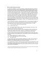
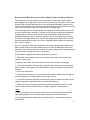
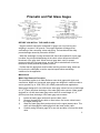
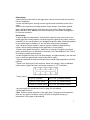
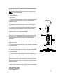
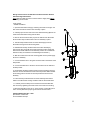
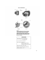
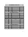
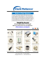
Section: R500.E153C
Bulletin: E153-C
Date: 5-10-09
Supersedes: E153-A-1
World’s Leader in Boiler Trim
Instrumentation & Controls
Prismatic and Flat Glass
Water Gage Maintenance
Instructions
Flat Glass Gage Glass
Prismatic Gage Glass
16633 Foltz Parkway, Strongsville, OH 44149 USA
Telephone: (440) 572-1500 Fax: (440) 238-8828
www.clark-reliance.com
Unpacking and inspection
Upon receipt of the Boiler Drum Level instruments, examine the contents of the
container(s) for damage. Report any faulty conditions as soon as possible to your
carrier to avoid acceptance of damaged goods. Clark-Reliance will not be
responsible for goods damaged in shipping or storage, or subsequent loss or
damage due to improper storage or exposure as a result of damage to shipping
containers. Submit a digital photo of any damaged equipment and container to
Clark-Reliance, if possible
Verify that all materials are present as recorded on the Packing List provided with
each shipment. Report any discrepancies to Clark-Reliance immediately. Have the
Clark-Reliance order number and shipping waybill available at the time of your call.
Handling
Your Clark-Reliance shipment has been carefully packed. However, the shipment
may include spare parts, temporary water gages for “Boil-out” purposes,
maintenance instructions, and engineering drawings.
Upon receipt of the order, the equipment and above items should be identified and
verified against the packing list. Any documentation that has been provided should
be directed to the appropriate personnel.
Care should be exercised as the items are uncrated. The shipment may contain
fragile glass components. If any equipment appears to have been damaged from
shipment, please contact your local Clark-Reliance representative or the factory
immediately.
Storage
Clark-Reliance Boiler Trim products should be stored in a dry and sheltered area
prior to installation. The equipment provided may consist of electrical items that are
intended for either indoor or outdoor use. As a matter of good practice, dry storage
will eliminate the potential for water damage.
The temperature of the storage area should not exceed 150 degrees F. (65.5
degrees C) or drop below 32 degrees F (0 degrees C).
2
Boil-out Gage Practice and Policy
On new boiler installations, it is common procedure to initially operate the boiler at a reduced
pressure for a short time to ‘cook out’ foreign materials (pipe joint compound, grease, oil, flux,
etc.) that remain in the drum or other pressurized parts of the system after the boiler has been
constructed. During this boil-out period, most of the suspended or dissolved debris is flushed
out with blow-down discharges. However, a small amount of residue is unavoidably deposited
as a film on all internal wetted surfaces… including those of the water gage glass. This type of
scum layer is nearly impossible to remove by blowing down the gage glass, particularly if the
gage glasses are protected by mica shields, as they must be, in high pressure installations.
As a practical matter, it is more expedient to employ an inexpensive temporary level gage,
which can be discarded or returned after the boil-out procedure, rather than to use then rebuild
the gage glass intended for regular service. For boil-out purposes on new water columns, ClarkReliance provides a temporary level gage at no charge, or at a refundable charge, under one of
the following conditions:
1) When a Prismatic, Flat Glass, or Simpliport gage having ¾” O.D. end nipples is supplied as
part of a water column, and the boil-out pressure will not exceed 200 PSIG, Clark-Reliance
automatically will furnish for temporary boil-out service the following parts at no charge:
1 pc. – ¾” O.D. tubular glass gage cut to the proper length
2 pcs. – Rubber packing rings (*)
1 pc. – Low visibility shield (so that low vision in the tubular glass gage is the same as in the
gage glass that will be used for regular service).
At the conclusion of the boil-out procedure, all of the above parts should be discarded. When
the gage having stainless steel nipples is installed, it is essential that the appropriate (nonrubber) packing rings are used, to assure durable sealing of the stainless steel nipples.
2) When a gage glass having flanged connections is supplied as part of a water column, and
the boil-out pressure will not exceed 200 PSIG, Clark-Reliance will furnish the following parts at
no charge:
1 set – VB991 gage valves with ½” MNPT connections
1 pc. 5/8” O.D. tubular glass gage cut to the proper length
1 pc. – Low visibility shield.
The boil-out gage valves should be temporarily installed in the ½” FNPT “Test” connections in
the flanges of the regular water gage shut-off valves, which are on the water column. This
equipment may be discarded after the boil-out has been completed.
3) On installations like the above, but where the boil-out pressure will exceed 200 PSIG, consult
Clark-Reliance to discuss options for an appropriate temporary use gage and valves. The cost
of this assembly will be listed separately on our order invoice. However, full credit will be issued
upon its return to Clark-Reliance.
* Bronze valves are supplied with rubber packing rings. These are to be used for the boil-out procedure. Steel valves are supplied
with packing cartridges and separate rubber packing rings (to beused for boil-out).
3
Recommended Blow-Down Procedure for Water Columns and Gage Glasses
The importance of proper cleaning and maintenance of the water column and the
water gage glass, or sight glass, cannot be stressed enough. The water column must
he kept clean to ensure the water level in the gage glass accurately represents the
water level in the boiler. Note that the frequency and method of blow-down may affect
service life and performance of the water column and gage glass.
The water gage glass on a boiler enables the operator to visually observe and verify
the actual water level in the boiler. However, if not properly cleaned and maintained,
a gage glass can seem to show that there is sufficient water, when the boiler is
actually operating in a low or low water condition. A stain or coating can develop on
the inside of the glass where it is in contact with boiling water. After a time, this stain
gives the appearance of water in the boiler, especially when the glass is completely
full or empty of water.
Also, the connection lines to the gage glass can become clogged with sediment and
show normal water levels when water may be low. After performing the blow-down
procedure, if the water level does not return to normal promptly, the connecting piping
may be partially clogged and have to be cleaned.
Clark-Reliance suggests the following blow-down procedure:
1. Close both the steam and water valves between the boiler drumand the water
column or water gage.
2. Open the drain valve fully on the bottom of the water column or water gage.
3. Crack open the steam valve and allow a gentle rush of steam to pass through the
water column or water gage. The steam should not pass through for longer than 20
seconds.
4. Close the steam valve.
5. Inspect the water gage to insure that all foreign matter is flushed from the glass or
mica. If the gage is not visually clean, repeat steps 3 and 4.
6. Close the blow-down valve and simultaneously open the steam and water valves,
slowly bringing the equipment back to a normal operating level.
7. Water should enter the gage glass quickly when the blow-down valve is closed.
This will indicate that the lines are free of sludge, sediment, or scale buildup.
Note:
1. Any trip or alarm circuits that are actuated by the equipment being blown-down
should be bypassed to prevent false alarms during the blow-down process.
2. Blow-down should be conducted on a weekly basis, or as necessary, based on
water quality.
4
3. Always notify control room personnel prior to conducting a Blo w-Down to
prevent any false alarms or false trips.
Recommended Maintenance and Annual Inspections
Regarding any recommended maintenance procedures or annual inspections, we
suggest any device containing probes should be inspected on an annual basis for
contaminated probes and wire secure terminations.
Caution: Before proceeding, follow any and all plant lock out - tag out procedures
required. Verify that all power is turned off to the probes. If under pressure, the
equipment should be isolated, or the boiler should be shut down before
proceeding with the installation. Open drain valve to eliminate any trapped
pressure. All inspection and installation steps should be performed by a qualified
technician and should be executed in accordance with all applicable national and
local codes.
With no pressure or elevated temperature, beyond ambient conditions, at least
one probe should be removed for inspection. Ideally, for devices containing
multiple probes, we suggest removing one probe from an upper indication location
(normally in steam area) and one probe from a lower indication location (normally
in water area) for inspection. If any probes display signs of contamination, they
can be cleaned with a mild detergent and re-installed using a new sealing gasket,
if applicable. Refer to the attached IOM # E189-A for additional details. If a probe
exhibits and contamination across the length of the insulator, which cannot be
easily cleaned, the probe should be replaced.
5
Prismatic and Flat Glass Gages
BEFORE YOU INSTALL THE GAGE GLASS:
- Support brackets should be considered for gages over four feet long and
weighing in excess of 100 pounds. The support brackets will help prevent
overloading of the connecting valves and piping. The brackets will also help
prevent damage caused by excessive vibration.
- While the advantage of using automatic ball check valves ahead of a level gage
is evident, the principal disadvantage is the check valves will prevent effective
blow-down of the gage itself. When the level gage drain valve is opened,
pressure inside the level gage drops, and the check valve balls are driven into
the almost closed positions by system pressure.
- Confirm that the gage glass model number and the pressure rating, which can
be found on the nameplate, meet the required specifications and design
conditions for the application.
Maintenance
Water Gage Removal Procedure
This procedure applies to all Clark-Reliance water level gages with nipple end
connections. Nipple end connected water gages are designed in various models to
service pressure up to 1500 PSIG (103.4 BarG) saturated steam applications.
Water gages designed for use with bronze water gage valves have an overall length
of 2 ¾” (70mm) less than the design of the water gage valve centers. Water gages
designed for use with steel water gage valves have an overall length of 3 ¼”
(82.5mm) less than the design of the water gage valve centers.
1)
Isolate the water gage valves and open the drain valve.
2)
Remove the packing yoke bolts on steel valves. On bronze valves loosen
the nipple packing nut.
3)
Grasp the water gage firmly and push up into the upper (steam) valve. This
action will disengage the water gage from the lower (water) valve.
4)
Carefully swing the water gage off to one side and drop it out from the steam
valve.
6
Disassembly:
-After pressure is relieved from the gage glass, remove from the boiler drum and lay
flat on a workbench
-Loosen end bolting first, working from the opposite ends toward the center of the
gage.
-Remove all components including washers, finger clamps, cover plates, gaskets,
glass, and Mica shields. Retain the bolting and cover plates. Discard all gaskets,
glass, and Mica. Note: Never re-use these components, even when they appear to
be in perfect condition!
Reassembly:
-Inspect all glass kit components. Verify that the repair kit is the correct one for the
model gage that is being repaired. Carefully inspect the glass for any chips, cracks or
scratches. Do not use the glass if it is damaged! Inspect the Mica shields and gaskets
for any visible signs of damage, Do not use these components if damaged!
-Use a bronze or brass scraper to remove any bits of gasket material that may
remain, without causing damage to the gage body or cover plate(s).
-Examine body gasket surfaces for steam cuts or scratches. Gouged or scratched
gasket surfaces may be re-machined if necessary. See Clark-Reliance Form E190-A
for machining details and tolerances.
-Locate the gaskets, Mica (if on Flat Glass Gages), and glass centrally in the seat and
cover to avoid any glass-metal contact at the ends or sides.
-Clean and lubricate all fasteners with Molycote or similar high temperature anti-seize
lubricant.
-Tighten nuts ‘finger tight’ in the sequence shown in the sketch. Using a calibrated
torque wrench, tighten all nuts in the proper sequence in 1/3rd increments.
-Torque values
‘C’ and ‘S’ Prismatic
40 Ft. Lbs. (54 Newton Meters)
FG400 or FG900 Series
45 Ft. Lbs. (61 Newton Meters)
FG1500 or FG2000 Series
70 Ft. Lbs. (95 Newton Meters)
-Hot torque gage per instructions found on page 8 of this manual.
-Return gage to service
-Note: Conduct regular inspection of the gage glass. The gage must be repaired if
there are any signs of scratches, etching, erosion of the glass, clouding,or
deterioration of the glass or Mica shields.
7
Recommendations and Instructions
for Hot Torquing Gage Glasses and
Probe Type Devices
When a new piece of equipment, whether a Gage Glass or a Probe* type device is
installed, the hot torque procedure must be performed. This ensures that all bolting
and components are properly seated for optimum performance. This procedure
must also be performed after any maintenance is done to the equipment. Note that
only the affected components, such as the installation of a new probe or glass kit,
need to be hot torqued.
All work must be done by a qualified technician. All plant rules and procedures
must be followed, including any lock out / tag out requirements. Verify that all
alarms and trips have been by-passed on probe columns before any maintenance
is performed, to prevent any false alarms or wiring hazards.
The hot torque procedure should be performed as follows:
1)
2)
3)
4)
5)
6)
7)
Isolate the gage glass or probe device from any pressure.
Fully open the drain valve to evacuate any built up pressures and to allow the
contained steam and water to escape during equipment warm up.
Slowly open the steam valve to allow a gentle rush of steam to flow through the
equipment. This should take approximately 5 – 10 minutes. The observer should
see the High Temperature lubricant “sizzling” and smoke emanating from the gage
of column. This is an indication that the equipment has reached the operating
temperature.
When the equipment has been properly heated, close the steam valve. The drain
valve should remain open to allow any residual steam or pressure to escape.
Immediately re-torque the equipment to the correct values stated in the applicable
instruction manual. There should be movement of approximately 1/8th of a turn or
more.
If there is no movement of the bolting or probes, the equipment was not heated
properly. Repeat the procedure.
Once the hot torque procedure is completed, close the drain valve, and the
equipment can be put back into service. Carefully check for any leaks in the
equipment and verify proper operation of all illumination, relay controls and wiring,
or other accessories.
8
Installation Instructions for Model GL-53 Water Gage Illuminators for
Tubular Glass Gages or Prismatic Gages
1.
General Information
Model GL-53 Water Gage Illuminators are designed to improve the vision of
the water level, for plant personnel. If a tubular glass or prismatic type water
gage is installed in an area with adequate lighting, a gage illuminator may not
be required. However, if the water gage is to be viewed from a distance
greater than 25 feet, or in poorly lit areas, then a gage illuminator is
recommended.
2.
Installation
Model GL-53 illuminators are designed with a ½” female NPT electrical conduit
connection. These illuminators should be installed vertically with the conduit
connection located at the bottom. A flexible power cord can be temporarily
installed on the unit, and used to test the unit. This will enable the installer to
optimize the illuminator location, with respect to the gage. CAUTION: when
testing the position of the unit, the housing will become very hot when
powered. Then, a permanent power connection can be installed. Normally,
the illuminator will be installed parallel to the gage and off to the left or right
side, to prevent obstructing the operator’s view of the water gage.
If the illuminator is to be installed with a prismatic type water gage, one
illuminator can be used for up to two sections of size 9 glass or approximately
27 inches of water gage viewing.
This illuminator can be installed outdoors.
3.
Maintenance
There is no maintenance required, other than the occasional need to service
the lamp. For additional instructions, see form E178-A. As an option to extend
lamp life, we suggest an illuminator timer: model TPS-120 (for 120 VAC
supply) or TPS-240 (for 240 supply). An illuminator timer provides up to 3
minutes of operation time, by depressing a pushbutton. This results in
extended lamp life, reduced power consumption and maintenance. Consult CR or your local representative for additional details.
9
Wiring instructions for the Clark • Reliance GL53 Illuminators
(for 'C' and 'S' Series Gages).
Note: Make sure that the power is turned off to the supply wiring
before connecting the illuminator.
Tools needed:
– Slotted Screwdriver
– 1/2" Wrench
1. Open the illuminator housing by loosening the three hex head cap
screws on the end of the unit that secures the Conduit/Lamp
assembly in place.
2. Carefully remove the assembly and remove the 60W Frosted
Lamp (B) from the illuminator housing and set aside.
3. Loosen the screw (C) from the side of the lamp socket/conduit
connector that holds the assembly in place on the pipe nipple.
4. Take the lamp socket/conduit connector assembly (D) off of the
housing end piece and set the housing aside.
5. Disassemble the lamp socket/conduit connection assembly by
removing the two screws (E) from inside of the lamp socket. (Note
that there are two small washers on the assembly screws. Do not
lose these washers as they are needed for re-assembling the
illuminator.)
7. Connect the black wire to the ‘gold’ screw terminal on the bottom
of the lamp socket.
8. Connect the white wire to the ‘silver’ screw terminal on the bottom
of the lamp socket.
9. Re-assemble the lamp socket/conduit connector assembly using
the same two screws with washers inside of the lamp socket. Make
sure that the mounting plate is centered on the lamp socket/conduit
connector assembly.
10. Thread the lamp socket/conduit connector assembly back into
the bottom of the pipe nipple and tighten the holding screw.
11. Carefully screw the lamp into the socket and re-assemble the
bottom assembly back onto the illuminator housing (make sure that
the gasket between the bottom assembly and housing is in place).
Secure by tightening the three hex head cap screws on the bottom
side of the housing.
12. Wire the illuminator to the 120 V.* power supply. (*Unless lamp is
for 230 V. service) Note that a proper ground wire is recommended.
GL53 Illuminator - 120V.
Specification: 60W/120V
Current Draw: .5 Amps
10
Wiring instructions for the Standard and Vertical Clark • Reliance
Flat Glass Gage Illuminators
Note: Make sure that the power is turned off to the supply wiring before
connecting the illuminator.
Tools needed:
– Slotted Screwdriver
1. Open the illuminator housing by loosening the thumb screw (A) in the
side of the unit that secures the door assembly in place.
2. Carefully open the door and remove the 150W clear lamp (B) from the
inside of the illuminator housing and set aside.
3. Remove the two brass screws (C) from the bottom of the illuminator
which hold the lamp socket/conduit connector assembly in place.
4. Take the lamp socket/conduit connector assembly (D) from the
illuminator housing and set the housing aside.
5. Disassemble the lamp socket/conduit connection assembly by
removing the two screws (E) from inside of the lamp socket. (Note that
there are two small washers on the assembly screws. Do not lose these
washers as they are needed for re-assembling the illuminator.)
6. Slide the conduit connector and mounting plate over the power supply
wires for re-assembly.
7. Connect the black wire to the ‘gold’ screw terminal on the bottom of the
lamp socket.
8. Connect the white wire to the ‘silver’ screw terminal on the bottom of
the lamp socket.
9. Re-assemble the lamp socket/conduit connector assembly using the
same two screws with washers inside of the lamp socket. Make sure that
the mounting plate is centered on the lamp socket/conduit connector
assembly.
10. Place the lamp socket/conduit connector assembly back into the
bottom of the illuminator housing and fasten with the two brassscrews.
11. Carefully screw the lamp into the socket and close the illuminator
door. Secure by tightening the thumb screw on the side of the housing.
12. Wire the illuminator to the 120 V.* power supply. (*Unless lamp is for
230 V. service) Note that a proper ground wire is recommended.
FG*0 Standard Illuminator - 120V.
Specification: 150W/120V
Current Draw: 1.25 Amps
11
12
Confirm that the correct supply voltage is being
applied to the illuminator power supply. The unit has
been manufactured for a specific power source,
either 120 or 240 VAC.
13
RECOMMENDED SPARE PARTS
PRISMATIC GAGE GLASS
Size/Type
Part No.
Description
Quantity
C4 or S4
RK-35
Repair Kit (incl. Glass & Gaskets)
1 per section
C5 or S5
RK-35A
Repair Kit (incl. Glass & Gaskets)
1 per section
C6 or S6
RK-35B
Repair Kit (incl. Glass & Gaskets)
1 per section
C7 or S7
RK-35C
Repair Kit (incl. Glass & Gaskets)
1 per section
C8 or S8
RK-35D
Repair Kit (incl. Glass & Gaskets)
1 per section
C9 or S9
RK-35E
Repair Kit (incl. Glass & Gaskets)
1 per section
FG400 / FG900 SERIES FLAT GAGE GLASS
Size/Type
Part No.
FG404/FG904
RK-4E-SET
Repair Kit Set (incl. Glass, Mica & Gaskets)
Description
Quantity (Set)
1 per section
FG405/FG905
RK-4F-SET
Repair Kit Set (incl. Glass, Mica & Gaskets)
1 per section
FG406/FG906
RK-4A-SET
Repair Kit Set (incl. Glass, Mica & Gaskets)
1 per section
FG407/FG907
RK-4B-SET
Repair Kit Set (incl. Glass, Mica & Gaskets)
1 per section
FG408/FG908
RK-4C-SET
Repair Kit Set (incl. Glass, Mica & Gaskets)
1 per section
FG409/FG909
RK-4D-SET
Repair Kit Set (incl. Glass, Mica & Gaskets)
1 per section
FG1500 SERIES FLAT GAGE GLASS
Size/Type
Part No.
Description
Quantity (Set)
FG1504
RK-5F-SET
Repair Kit Set (incl. Glass, Mica & Gaskets)
1 per section
FG1505
RK-5A-SET
Repair Kit Set (incl. Glass, Mica & Gaskets)
1 per section
FG1506
RK-5B-SET
Repair Kit Set (incl. Glass, Mica & Gaskets)
1 per section
FG1507
RK-5C-SET
Repair Kit Set (incl. Glass, Mica & Gaskets)
1 per section
FG1508
RK-5D-SET
Repair Kit Set (incl. Glass, Mica & Gaskets)
1 per section
FG1509
RK-5E-SET
Repair Kit Set (incl. Glass, Mica & Gaskets)
1 per section
FG2000 SERIES FLAT GAGE GLASS
Size/Type
Part No.
Description
Quantity (Set)
FG2004
RK-38-SET
Repair Kit Set (incl. Glass, Mica & Gaskets)
1 per section
FG2005
RK-39-SET
Repair Kit Set (incl. Glass, Mica & Gaskets)
1 per section
FG2006
RK-40-SET
Repair Kit Set (incl. Glass, Mica & Gaskets)
1 per section
FG2007
RK-41-SET
Repair Kit Set (incl. Glass, Mica & Gaskets)
1 per section
14
*** REPLACEMENT PARTS WARNING ***
The use of non-Original Equipment Manufacturer parts
(such as glass, gaskets, probes, modules, etc.) will void the
Agency Approval (FM, UL, CSA, CRN, ABS, etc.),
pressure/temperature rating, and warranty of this
equipment. Clark-Reliance requires the use of OEM parts for
all repairs on this product in order to maintain plant and
personnel safety, and reliable operation.
15
"PARTS-PLUS"
Critical spare parts for overnight
delivery, direct from the manufacturer.
clark-reliance.com/parts
Steel Valve Repair Kit
Replacement Probes
Gage Glass Repair Kit
Simpliport Module
Simpliport Packing Nut
Replacement Relays
Probe Repair Kit
Replacement EA100 Ass’y
Bronze Valve Repair Kit
Valve Packing
Replacement Floats
Replacement Micro-switch
16633 Foltz Parkway Strongsville, OH 44149 USA
Phone (440) 572-1500
Fax (440) 238-8828
[email protected] www.clark-reliance.com