1
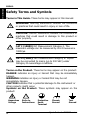
Quick Guide RIGOL Publication number QGA01106-1110 July 2009 DM3000 Series Digital Multimeter DM3061/2/4 DM3051/2/4 © 2008 RIGOL Technologies, Inc. All Rights Reserved RIGOL © 2008 RIGOL Technologies, Inc. All Rights Reserved. RIGOL products are protected by patent laws in and outside of the P.R. China. Information in this publication replaces all previous corresponding material. RIGOL reserves the right to modify or change part of or all the specifications and pricing policies at company’s sole decision. NOTE: RIGOL is registered trademark of RIGOL Technologies, Inc. Quick Guide for DM3000 series I ENGLISH RIGOL ENGLISH Safety Notice Review the following safety precautions carefully before operating the instrument to avoid any personal injuries or damages to the instrument and any products connected to it. The instrument should be serviced by qualified personnel only. To Avoid Fire or Personal Injury. Use Proper Power Cord. Use the power cord designed for the instrument as authorized in your country only. Ground the Instrument. The instrument is grounded through the grounding conductor of the power cord. To avoid electric shock the instrument grounding conductor(s) must be grounded properly before making connections to the input or output terminals of the instrument. Observe all Terminal Ratings. To avoid fire or shock hazard, observe all ratings and marks on the instrument. Follow the user’s guide for further ratings information before making connections to the instrument. Do not Operate Without Covers. Do not operate the instrument with covers or panels removed. Use Proper Fuse. Use the fuse of the type, voltage and current ratings as specified for the instrument. Avoid Circuit or Wire Exposure. Do not touch exposed connections and components when power is on. Do not Operate With Suspected Failures. If suspected damage occurs with the instrument, have it inspected by qualified service personnel before further operations. Do not Operate in Wet/Damp Conditions. Do not Operate in an Explosive atmosphere. Keep Product Surfaces Clean and Dry. The disturbance test of all the models meet the limit values of A in the standard of EN 61326: 1997+A1+A2+A3, but can’t meet the limit values of B. Input Terminal Protection Limitation Protection limitation is defined for the input terminal: 1. Main input (HI and LO) terminal HI and LO terminals are used for Voltage, Resistance, Capacitance, Continuity, Frequency and Diodes measurement. Two protection limitations are defined: 1) HI-LO protection limitation: 1000 VDC or 750 VAC. It is II Quick Guide for DM3000 series RIGOL Quick Guide for DM3000 series III ENGLISH the maximum measurable voltage. The limitation can be expressed as 1000 Vpk. 2) LO-ground protection limitation. LO terminal can safely “float” 500 Vpk relative to the ground. The maximum protection limitation of HI terminal relative to the ground is 1000 Vpk. Therefore, the sum of the “float” voltage and the measured voltage cannot exceed 1000 Vpk. 2. Sampling (HI Sense and LO Sense) terminal HI Sense and LO Sense are used for 4-Wire Resistance and Ratio Measurement. Two protection limitations are defined: 1) HI Sense-LO Sense protection limitation: 200Vpk. 2) LO Sense-LO protection limitation: 2Vpk. 3. Current input (I) terminal I and LO terminal are used for current measurement. The maximum current which go through the I terminal is limited to 10A by the fuse on the rear panel. NOTE: Voltage on the current input terminal corresponds to voltage on LO terminal. To obtain favorable protection, specified fuse should be used. IEC Measurement Category II Overvoltage Protection DM3000 can measure under IEC Measurement Category II. To protect against the danger of electric shock, DM3000 provides overvoltage protection for line-voltage mains connections meeting both of the following conditions: 1. The HI and LO input terminals are connected to the mains under Measurement Category II conditions, defined below. 2. The mains are limited to a maximum line voltage of 300 VAC. WARNING: IEC Measurement Category II includes electrical devices connected to mains at an outlet on a branch circuit. Such devices include most small appliances, test equipment, and other devices that plug into a branch outlet or socket. DM3000 may be used to make measurements with the HI and LO inputs connected to mains in such devices, or to the branch outlet itself (up to 300 VAC). However, DM3000 may not be used with its HI and LO inputs connected to mains in permanently installed electrical devices such as the main circuit-breaker panel, sub-panel disconnected boxes, or permanently wired motors. Such devices and circuits are subject to overvoltage that may exceed the protection limits of the DM3000 series Digital Multimeter. NOTE:Voltages above 300 VAC may be measured only in circuits that are isolated from mains. However, transient overvoltage is also present on circuits that are isolated from mains. DM3000 is designed to safely withstand occasional transient overvoltage up to 2500 Vpk. Do not use this equipment to measure circuits where transient overvoltage could exceed this level. RIGOL ENGLISH Safety Terms and Symbols Terms in This Guide. These terms may appear in this manual: ! WARNING: Warning statements indicate the conditions or practices that could result in injury or loss of life. ! CAUTION: Caution statements indicate the conditions or practices that could result in damage to this product or other property. ! CAT I (1000V) IEC Measurement Category I. The maximum voltage can be measured by HI-LO terminal is 1000Vpk. ! CAT II (300V): IEC Measurement Category II. Inputs may be connected to mains (up to 300 VAC) under Category II overvoltage conditions. Terms on the Product. These terms may appear on the product: DANGER indicates an injury or hazard that may be immediately happen. WARNING indicates an injury or hazard that may be not immediately happen. CAUTION indicates that a potential damage to the instrument or other property might occur. Symbols on the Product. These symbols may appear on the product: ! Hazardous Voltage IV Refer to Instructions Protective Earth Terminal Chassis Ground Test Ground Quick Guide for DM3000 series RIGOL ENGLISH Contents Contents .................................................................................. V Necessary Inspection ................................................................ 1 Handle Adjustment ................................................................... 4 To Connect Power Cord ............................................................. 5 To Connect Test Lead................................................................ 7 To Connect Inspection Junction Box .......................................... 13 To Connect USB, RS232, LAN and GPIB Ports ............................ 14 Troubleshooting....................................................................... 15 Contact RIGOL ....................................................................... 16 Quick Guide for DM3000 series V RIGOL ENGLISH General Inspection 1. Inspect the shipping container for damage. Keep the damaged shipping container or cushioning material until the contents of the shipment have been checked for completeness and the instrument has been checked mechanically and electrically. 2. Inspect the instrument. In case there is any mechanical damage or defect, notify the RIGOL Sales Representative. If the shipping container is damaged, or the cushioning materials show signs of stress, notify the carrier as well as the RIGOL sales office. Keep the shipping materials for the carrier’s inspection. 3. Check the accessories. Accessories supplied with the instrument are listed in the following pages. If the contents are incomplete or damaged notify the RIGOL Sales Representative. Quick Guide for DM3000 series 1 RIGOL ENGLISH I. Front Panel of the Instrument DM3000 Front Panel II. Standard Accessory 2 A Power Cord Two Test Leads (red, black) A USB Cable Two Backup Fuses Quick Guide for DM3000 series RIGOL ENGLISH A Quick Guide Inspection Junction Box** A CD-ROM* Inspection Card Extended Line** NOTE*: The CD-ROM includes《User’s Guide》and Application Software. NOTE**: The inspection junction box and inspection card extended line are the specific accessories for DM3064/DM3054, and the inspection card extended line is optional. III. Optional Accessory RS232 Cable Kelvin Test Clip NOTE: All the accessories (standard and optional) are available by contacting your local RIGOL office. Quick Guide for DM3000 series 3 RIGOL ENGLISH Handle Adjustment To adjust the handle position of DM3000 Multimeter, please grip the handle by the sides and pull it outward. Then, rotate the handle to the desired position as shown the following figure: To Adjust the Handle Viewing Positions 4 Carrying Position Quick Guide for DM3000 series RIGOL ENGLISH To Connect Power Cord Before you connect the instrument to a power source, please select the voltage selector according to the power supply. Then, connect the power cord as shown in the following figure. To Connect Power Cord Turn on the power switch on the rear panel, then press the power key on the front panel to start up the Multimeter. If unable to start up the Multimeter, take the following steps: 1. Check the power cord connection; 2. Check if the power switch on the rear panel has been turned on; 3. After the inspections, if the power key is not lit, please take out the fuse and check, change the fuse if needed. 4. After the above inspections, the power key is still not lit, please contact RIGOL for help. Quick Guide for DM3000 series 5 RIGOL ENGLISH Power Selection The Multimeter can operate on multiple power distribution standards and must be set up to operate on the line voltage that will power it. If the selected line voltage does not match the power that the Multimeter will be plugged into, the Multimeter’s linevoltage setting must be changed. The power selector is under the power switch on the rear panel. To change the fuse The fuse located in the rear panel of the Multimeter, it is a kind of fast-melt, no-burst, T300mA, 5× 20mm one. To Change the Fuse Operation steps: 1. Disconnect the power. Use the Straight Screwdriver to press down the block (as the dashed line point out), and then pull out the seat of the fuse. 2. Choose the correct voltage shelves location in the voltage selected switches. 3. Enclose the seat of the fuse to the slot after placed the fuse. ! 6 WARNING: To avoid electric shock or fire, do not use makeshift fuses or short-circuit the fuse holder. Quick Guide for DM3000 series RIGOL ENGLISH To Connect Test Lead 1. DC Voltage Measurement Connect test leads as shown in the following figure; red test lead to the HI Terminal, black test lead to the LO Terminal. DC Voltage 2. AC Voltage Measurement Connect test leads as shown in the following figure; red test lead to the HI Terminal, black test lead to the LO Terminal. AC Voltage Quick Guide for DM3000 series 7 RIGOL ENGLISH 3. DC Current Measurement Connect test leads as shown in the following figure; red test lead to the Current Input I Terminal, black test lead to the LO Terminal. DC Current 4. AC Current Measurement Connect test leads as shown in the following figure; red test lead to the Current Input I Terminal, black test lead to the LO Terminal. AC Current 8 Quick Guide for DM3000 series RIGOL Connect test leads as shown in the following figure; red test lead to the HI Terminal, black test lead to the LO Terminal. I Resistance 6. 4-Wire Resistance Measurement Connect test leads as shown in the following figure; red test lead to the HI Terminal, black test lead to the LO Terminal. 4-Wire Sense HI I Resistance 4-Wire Sense LO Quick Guide for DM3000 series 9 ENGLISH 5. 2-Wire Resistance Measurement RIGOL ENGLISH 7. Capacitance Measurement Connect test leads with the Capacitance as shown in the following figure; red test lead to the positive pole, black test lead to the negative pole. Capacitance 8. Continuity Testing Connect test leads as shown in the following figure; red test lead to the HI Terminal, black test lead to the LO Terminal. I Open or Closed Circuit 10 Quick Guide for DM3000 series RIGOL I Forward Bias 10.Frequency/Period Measurement Connect test leads as shown in the following figure; red test lead to the HI Terminal, black test lead to the LO Terminal. AC Signal Quick Guide for DM3000 series 11 ENGLISH 9. Diode Testing Connect test leads as shown in the following figure; red test lead to the HI Terminal, black test lead to the LO Terminal. RIGOL ENGLISH 11.Sensor Measurement Sensor Signal Voltage, Resistance and Frequency Sensor Sensor Current Sensor 12 Quick Guide for DM3000 series RIGOL ENGLISH To Connect Inspection Junction Box Model DM3064 and DM3054 have a built-in 16-channels inspection module. Users can use this module to measure multi-channels alternately and do data acquisition. Measured signals are inputted to DM3000 by connecting the inspection junction box as shown in the following figure. Connect Inspection Junction Box Measurement characteristic Channels: 12 voltage channels, 4 current channels Measurement Functions: DCV, DCI, ACV, ACI, 2WR, Capacitance, Continuity, Diodes and Frequency. Quick Guide for DM3000 series 13 RIGOL ENGLISH To Connect USB, RS232, LAN and GPIB Ports DM3000 has plenty of I/O ports. To use any of the ports, follow the next instruction. Connect USB Host Connect RS232 Port 14 Connect USB Device Connect LAN Port Connect GPIB Port Quick Guide for DM3000 series RIGOL ENGLISH Troubleshooting 1. When press the power switch, the Multimeter has blank screen with nothing displaying: (1) Check if the power is correctly connected. (2) Check if the main power switch on the rear panel has been turned on. (3) Check if the safety fuse has been blown, replace it if necessary. (4) Restart the instrument. (5) If it still can’t work properly, please contact RIGOL for help. 2. when connecting a current signal, the reading has any change: (1) Check if the test lead is correctly connected to current jack or the LO jack. (2) Check if the safety fuse in the current location on the back panel has been blown. (3) Check if the measure location has switched to the DCI or ACI place correctly. (4) Check whether the input is ACI but the shelves location is DCI. 3. when connecting a DC power signal, the reading display is abnormality: (1) Check if the test lead is correctly connected with the current jack or the LO jack. (2) Check if the safety fuse in the current location on the back panel has been blown. (3) Check the measure location has switched to the DCI or DCV place correctly. (4) Check whether the input is DCI but the shelves location is ACI. Quick Guide for DM3000 series 15 RIGOL ENGLISH Contact RIGOL If you have any problem or requirement occurs when using our products, please contact RIGOL Technologies, Inc. or the local distributors. In China: Please call Tel: (86-10) 8070 6688 Fax: (86-10) 8070 5070 Service & Support Hotline: 800 810 0002 9:00 am–5: 00 pm from Monday to Friday Or by e-mail: [email protected] Or mail to: RIGOL Technologies, Inc. 156# CaiHe Village, ShaHe Town, ChangPing District, Beijing, China Post Code: 102206 Overseas: Contact the local RIGOL distributors or sales office. For the latest product information and service, visit our website: www.rigolna.com 16 Quick Guide for DM3000 series