1
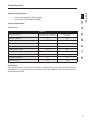
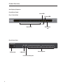
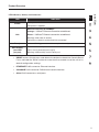
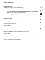
OmniView Serial
Console Server
®
User Manual
F1DP116Sea
Table of Contents
Product Overview....................................................................................................................1
Introduction....................................................................................................................... 1
Package Contents............................................................................................................. 1
Console Server Features................................................................................................... 2
Equipment Requirements................................................................................................. 3
System Requirements....................................................................................................... 3
Unit Display Diagrams....................................................................................................... 4
LED Indicators, Button, and Connectors.......................................................................... 5
Specifications.................................................................................................................... 6
Local Installation.....................................................................................................................7
Desktop or Rack-Mounting............................................................................................... 8
Connecting the Target Devices to the Console Server..................................................... 9
Network Configuration..........................................................................................................10
Web-Browser Interface................................................................................................... 10
Assigning IP from the Console Port--VT-100 (Console, Telnet, SSH)............................ 13
Web-Browser Management Interface............................................................................. 16
Network Settings...................................................................................................................18
IP Configuration.............................................................................................................. 18
IP Filtering....................................................................................................................... 19
Web-Server Configuration.............................................................................................. 21
Local........................................................................................................................... 21
RADIUS and Local...................................................................................................... 21
Dynamic DNS.................................................................................................................. 22
RADIUS........................................................................................................................... 23
RADIUS-Server Configuration......................................................................................... 24
HTTPS/SSL..................................................................................................................... 24
Serial Ports...........................................................................................................................25
Configuration................................................................................................................... 25
Port Authentication................................................................................................... 25
Port Enable/Disable.................................................................................................. 26
Port Title.................................................................................................................... 26
Operation Modes...................................................................................................... 27
Console-Server Mode......................................................................................... 27
Terminal-Server Mode........................................................................................ 28
Dial-In Modem Mode.......................................................................................... 29
Serial-Port Parameters.............................................................................................. 29
Port Logging............................................................................................................. 30
Break Function.......................................................................................................... 31
Connection...................................................................................................................... 31
Telnet Java Applet.................................................................................................... 32
Serial-to-Serial Function................................................................................................. 34
Table of Contents
System Status and Log..........................................................................................................37
System Status................................................................................................................. 37
System Logging.............................................................................................................. 37
System Administration..........................................................................................................39
User Administration......................................................................................................... 39
Add User................................................................................................................... 39
Remove User............................................................................................................ 40
Edit the Access Control List (ACL)............................................................................ 41
Change Password..................................................................................................... 42
Date and Time (NTP) ...................................................................................................... 42
Firmware Upgrade.......................................................................................................... 43
Upgrade from the Web Interface.............................................................................. 43
SSL Certificate................................................................................................................ 44
Secure HTTP Certificate........................................................................................... 45
Reset to Factory-Default Settings................................................................................... 49
Reboot............................................................................................................................ 49
Technical Data.......................................................................................................................50
Default Settings............................................................................................................... 50
Appendix A: Adapters............................................................................................................51
Appendix B: Ethernet Pin-Outs (RJ45) ..................................................................................54
Standard Ethernet Cable RJ45 Pin-Out.......................................................................... 54
Appendix C: Well-Known TCP/UDP Port Numbers................................................................55
Appendix D: Protocol Glossary..............................................................................................56
Appendix E: Creating CA Files...............................................................................................58
Information............................................................................................................................60
Product Overview
section
Introduction
Thank you for purchasing the Belkin OmniView Serial Console Server (Console Server). This
device provides administrators secure monitoring and control of servers, routers, switches,
and other serial devices from anywhere on the corporate TCP/IP network, over the Internet,
or through dial-up modem connections, even when the server is unavailable through the
network.
The Console Server provides the following:
• Data-path security by means of SSH or Web/SSL
• A secure, encrypted web interface over SSL (HTTPS)
• SSHv2 encryption, to keep server access passwords safe from hackers
• Support for all popular SSH clients
• Secure access from any Java-enabled browser
• C
onnections to serial-console ports using standard CAT5 cables, eliminating the
hassles of custom cabling
Package Contents
1 x OmniView Serial Console Server
1 x AC Power Cord
5 x Serial-to-RJ45 Adapter Kit (5 pcs)
1 x Local Console Port Serial Adapter
1 x 6 ft. RJ45-RJ45 CAT5 Cable
1 x Quick-Start Guide
1 x User Manual CD
1 x Rack-Mount Brackets and Screws
1 x Footpad Set
1
Product Overview
Console Server Features
• In-band and out-of-band management
Console port management solutions offer remote, reliable, and secure access to serialconsole ports through in-band networks and out-of-band connectivity options, such as
serial terminal access and dial-up modem.
• Manage network devices/servers centrally, remotely, and securely
Reliable console-port management solutions allow you to encrypt sensitive data using
proven protocols such as SSH/v2, SSL.
• Diverse devices management
Simple ASCII or VT-100 terminal emulation is not sufficient to manage these wideranging device types. Today’s data centers contain a broad mix of UNIX®, Linux®, RISC,
mainframe, and Windows® servers, as well as other serially managed devices such as
router, gateway, firewall, PBX, UPS, SAN, and NAS devices, and intelligent power strips.
• Proactive monitoring and warning to assist system diagnosis
Applications, and even operating systems, send messages to the system console.
These messages contain error and panic information that often precedes a system
crash. Unlike terminal servers, console-port servers buffer these messages in real time
and allow administrators to page through and search this data at a later time; they also
spontaneously send an email to alert IT administrator of the critical event.
• Remote and secure power controller
Via serial port, this device acts as control master for controlling power strips. It can
control multiple power strips (up to 15).
• Provides serial-to-serial function
This allows the device to incorporate with a terminal converter to provide VGA and
keyboard ports locally, or connect the VGA/keyboard ports to a KVM switch to
consolidate the administration.
• Access port lists for users
Thanks to the Access Control List (ACL) of user account administration, all users except
admin accounts, are authorized a set of serial ports. Users can access and make
configuration changes to those authorized serial ports assigned by an admin account.
2
Product Overview
section
Equipment Requirements
• Universal Connectivity Kit (included)
• RJ45-RJ45 CAT5 Cable (included)
System Requirements
Web browser
Browser
Microsoft Internet Explorer
version 6.0 SP1 and later
Firefox version 2.0
and later
Windows 2000 SP2
Yes
Yes
Windows Server 2003
Yes
Yes
Windows XP
Yes
Yes
Windows Vista
Yes
Yes
Red Hat Linux 3 and 4
No
Yes
Sun Solaris 9 and 10
No
Yes
Novell SUSE Linux 9 and 10
No
Yes
Fedora Core 4 and 5
No
Yes
Mac OS X 10.4+
No
Yes
Operating System
Java Plug-In
The Console Server’s web interface requires installing JRE (Java Runtime Environment) v6.0
and above. You can get the latest Java software from the website: http://www.java.com/en/
download/manual.jsp.
3
Product Overview
Unit Display Diagrams
Front/Rear Panel
Link LED
Fig. 1 Front View
Power LED
Ready LED
Port LEDs
Reset button
Fig. 2 Rear View
IEC power
LAN port
Local console port
4
Device ports
Product Overview
LED
Power
section
LED Indicators, Button, and Connectors
Indication
Red – power indication
ON: power is applied
Ethernet Link/Act/10/100Mbps:
Orange – 10BaseT Ethernet connection established
Link
Green – 100BaseT Ethernet connection established
Blinking: when data in activity
ON: when no data in activity and link connected
Ready
Port Activity
(one LED
per port)
Green – blinking per second when system is ready
Blue – traffic activity
ON: in use (successful port log-in)
Blinking: traffic activity on the serial port
• R
ESET button: Quickly press and release the button to reboot the Console Server.
Press and hold the “Reset” button for more than five seconds to set the unit to its
default configuration settings.
• ETHERNET RJ45 connector: Ethernet interface
• CONSOLE RJ45 connector: RS232 local console interface
• Other RJ45 connectors: serial ports
5
Product Overview
Specifications
Feature
General
Specification
LEDs
Power (red)
Ready (green, normally blinking),
Link/Act/10/100Mbps (Ethernet orange: 10Mbps, green: 100Mbps)
Activity (blue for each serial port)
Push button for reset, or restore to default
RTC (real-time clock)
16-port (F1DP116S)
Serial-port mode (RS232)
Serial Interface
Serial connector (RJ45)
Baud rate (300 to 115200)
Flow control (None, RTS/CTS, Xon/Xoff)
RJ45 connector
LAN Interface
IEEE 802.3 - 10/100BaseT
Auto-detecting, full/half-duplex selectable
Operation Modes
Console server
Port Function
Terminal server
Dial-in modem
Serial-to-serial (on port 16 only)
TCP, UDP, IP, ARP, ICMP, HTTP/HTTPS, Telnet, DHCP/BOOTP, PPP,
Protocols
SMTP, DNS, NTP
Dynamic DNS
TCP inactivity time (TCP keep-alive time)
Protocol Relative
Function
Serial inactivity time
Port monitoring
Password access
Security
IP filtering
SSHv2
HTTPS/SSL
Local user database
Authentication
PAP/CHAP (for modem dial-in)
RADIUS
Local console (menu or command line)
SSH, telnet
Management
Web pages (HTTP/HTTPS)
Firmware upgrade via web interface
Port buffering and logging
Full-featured system status display
AC Input (100 ~ 240VAC, 50 ~ 60Hz)
Power and
Environment
Operating Temperature: -10° to 80° C
Storage Temperature: -20° to 85° C
Humidity: 0–90% non-condensing
Certifications
Mechanical
CE, FCC
UL
1U 19˝ rack-mount
Dimensions (cm): 43.2 x 18.0 x 4.2
Note: Specifications are subject to change without notice.
6
Local Installation
section
Where to place the Console Server:
The enclosure of the Console Server is designed for stand-alone or rack-mount
configuration. The Console Server can be mounted to a standard 19-inch server rack using
the included rack-mount brackets and screws.
Consider the following when deciding where to place the Console Server:
• the location of your target devices in relation to your console
• the lengths of the cables you use to connect your devices to the console
• the power source - Connect only to the power source specified on the unit.
When multiple electrical components are installed in a rack, ensure that the total
component power ratings do not exceed circuit capabilities.
Cable-Length Requirements (for CAT5)
Serial binary data signals (RS232) transmit best up to distances of 50 feet (15m). Beyond that
length, the probability of signal degradation increases. For this reason, Belkin recommends
that the length of the CAT5 UTP cable between the Console Server and the connected
servers does not exceed 50 feet (15m).
Cables and Adapters
Belkin highly recommends you use Belkin Category 5e, FastCAT5e, or Category 6 Patch
Cables for your Console Server to help ensure the signal integrity.
Belkin UTP Patch Cables:
A3L791-XX-YYY (CAT5e)
A3L850-XX-YYY (FastCAT™ 5e)
A3L980-XX-YYY (CAT6)
Refer to Appendix B on page 54 for pin-out guide.
Belkin Serial Adapter:
F1D120ea (RJ45F – DB9F DTE)
F1D121ea (RJ45F – DB25F DTE)
F1D122ea (RJ45F – DB25M DCE)
F1D123ea (RJ45F – DB25M DTE)
F1D124ea (RJ45F – RJ45M CISCO)
F1D120ea-8PK (8-pack of F1D120ea)
F1D124ea-8PK (8-pack of F1D124ea)
Refer to Appendix A on page 51 for detailed drawings of each Serial Adapter.
7
Local Installation
Desktop or Rack-Mounting
The Console Server can be placed on desktops or rack-mounted on 19-inch/1U racks.
Note: Before you begin, locate the MAC address and serial number on the back of the
Console Server. You may need these numbers later in the installation process, so it is highly
recommended that you record these numbers below before mounting the Console Server to
your rack.
MAC Address
Serial Number
The Console Server includes adjustable mounting brackets ideal for installation in 19-inch
racks. The mounting brackets feature three adjustment positions that allow you to set the
Console Server’s face flush with the ends of the rails, or to extend the Console Server past
the front of the rails. Please follow these simple steps to achieve the desired adjustment.
Rack-Mounting
1.Determine how far you would like the Console Server to protrude from the rack.
Select a bracket-hole scheme.
2.Attach the bracket to the side of the Console Server using the Phillips screws
provided. (Refer to diagram below.)
3.Mount the Console Server to the rack rails and secure with screws. (Refer to
diagram below.)
Your Console Server is now mounted securely to the rack and you are ready to connect your
target devices.
8
Local Installation
section
Connecting the Target Devices to the Console Server
1.Power down the target device(s) that will be connected to your Console Server.
2. Connect the Ethernet cable to the port labeled LAN.
3.Locate the included power cord and plug the appropriate end into the power
socket on the rear of the Console Server. Plug the other end into an appropriate AC
wall outlet.
Note: Allow about 100 seconds for the Console Server to complete the boot-up process.
4.Choose an available numbered port on the rear of your Console Server. Plug one
end of a UTP patch cable (4-pair, up to 15 meters) into the selected port, and plug
the other end into the target device. You may need to add the appropriate adapter
to interface with your target device. Please refer to Appendix A on page 51 in this
manual for more details.
5. Repeat this procedure for all target devices. (Refer to diagram below.)
CAT5 cable
(straight)
CAT5 cable
CAT5 cable
OR
Ethernet port
Local console
port adapter
CAT5 cable
(straight)
RJ45-toDB9M
adapter
CAT5 cable
(straight)
DB9F
Modem
Devices to be controlled
Controlling host
Controlling host
Fig. 3 Cabling Connection Setup—This diagram depicts sample cable connections for
different interfaces.
9
Network Configuration
Before you can connect to a target device, you will need to configure the network settings.
The Console Server offers two methods of setting the network: via web-browser interface or
through the local console port.
The Console Server offers support for both Dynamic Host Configuration Protocol (DHCP)
and static IP addressing. Belkin recommends that an IP address be reserved for the Console
Server and that it remains static while connected to the network.
Web-Browser Interface
The web interface provides an easy way to configure the Console Server. The administrator
can configure all features through the Web.
Initial Settings
The following section provides instructions for setting the IP address for the OmniView Serial
Console Server.
Step 1 Identifying the IP Address
Once your Console Server has been connected to your network and is powered up, a
Dynamic Host Configuration Protocol (DHCP) server on your network will automatically
assign the Console Server an IP address, gateway address, and subnet mask.
To identify the IP address on your network, use the MAC address located on the back of the
Console Server. If no DHCP server is found on your network, the Console Server will boot
with the following static IP address: 192.168.2.156.
If you want to connect more than one Console Server to the same network and there is no
DHCP server available, connect each Console Server to your network one at a time, and
change the static IP address of each unit before connecting the next unit.
Note: If a DHCP server later becomes available on your network, the Console Server
will take a new IP address from the DHCP server. To keep the original static IP
address, you will need to disable DHCP (see page 18).
Step 2 Logging into the Web Interface
After you identified the IP address of your device, open your web browser. A list of
supported browsers can be found on page 3.
Type in the Console Server’s IP address in the browser’s address field, using this format:
http://XXX.XXX.XXX.XXX (example: http://76.255.43.173). The login page will appear (see
next page). Bookmark the page for easy reference.
10
Network Configuration
section
Note: HTTPS can be used for communication over an encrypted secure socket layer
(SSL). When first connecting to the Console Server’s HTTPS configuration page, two
browser security warnings may appear. Click “Yes” on both warnings.
Login Page
Type in the following default user name and password (case-sensitive):
User Name
Password
admin
admin
There are two levels of access privileges:
User Name
Default Password
Access Privileges
admin
admin
Full access
(user define)
(user define)
Only can access “Serial Port” and
“System Status”
The administrator can add or remove a user easily via the web pages of system
administration.
11
Network Configuration
Click
Login
. The web interface will open at the “Connect” page (see below).
Main-Connect Page
Step 3 Network Configuration
Click on “Network” to open the Network-Configuration page (see below).
Network-Configuration Page
Here you can assign a static IP and other network settings.
Click on “Save & Reboot” to store any network-configuration settings.
Note: If the user leaves the web browser idle for more than 30 minutes, the login session will
time-out and terminate the session.
12
Network Configuration
section
Assigning IP from the Console Port—VT-100 (Console, Telnet, SSH)
The Console Server also offers a user-friendly, menu-driven command-line interface. You
can simply connect a VT-100 terminal to the local console port to access the Console
Server. This is useful when you do not know the network settings of the Console Server, and
cannot access it. Through the local console port, you can view or change the settings (IP
address, subnet mask, etc.).
1.Connect the console port on the rear panel to a serial port on a PC host using
the CAT5 cable and the local console port RJ45/DB9F adapter, included with the
Belkin Console Server.
2.Configure a terminal emulation program, such as HyperTerminal, using the
following parameters:
•
Baud rate = 115200
•
Data bits = 8
•
Stop bits = 1
•
Parity = none
•
Flow control = none
Note: User names and passwords are the same as the ones set through the web interface.
The defaults are “admin/admin”.
13
Network Configuration
The following figure depicts the structure of the interface.
Tier 1 menu
Product name
Software version
Tier 2 menu
Tier 3 menu
Configuration input
Navigation input
The Menu Layout
14
Network Configuration
section
Network > IP Config
The page to the left shows the IP configuration items.
1.For IP mode — You can press the SPACE bar to select Static mode or DHCP
mode.
2.For IP Address, Subnet Mask, Default Gateway, Primary DNS, and Secondary
DNS — You can change these network settings.
3.After changing the settings and the final enter, the Console Server will prompt you
to confirm YES or NO. If YES, the Console Server will reboot and save the settings
into the flash memory.
Network > Current IP
To show the current network settings.
Network > IP Filter
To enable/disable IP filter function.
System > Reboot
To reboot the Console Server.
System > Reset to Default
To reset configuration to factory-default settings.
Note: Only the admin user has the privilege to perform this function.
System > Status
To show the system status.
S-to-S > Select Serial-to-Serial Port
To enable serial port-to-serial port connection through port 16. Refer to the “Serial-to-Serial
Function” section on page 34 for more details.
15
Network Configuration
Note:
Only the admin user has the privilege to log in to VT-100. All the other users are not
authorized to make configuration with VT-100.
Web-Browser Management Interface
The Console Server supports both HTTP and HTTPS (HTTP over SSL) protocols. Users must
authenticate themselves by logging in to the system with a correct user name and password.
To access the Console Server’s web-management pages, enter the unit’s IP address or
resolvable host name into the web browser’s URL/location field. This will direct you to the
login screen.
The figure on the next page shows the home page of the web-management interface. A
menu bar displays along the top of the page. The submenu will display along the left side of
the page, and will allow you to modify parameter settings for the top-menu item selected.
16
Network Configuration
section
Where available, the page will allow users to apply or cancel their actions. To apply all
changes, select “Apply” and the new values will be applied to the configuration. If you do not
want to save the new values, simply click “Cancel” and all changes made will be removed
and the previous values restored.
17
Network Settings
You can configure the network IP settings via VT-100 or web interface. This section
describes configuration through the web interface.
IP Configuration
The Console Server requires a valid IP address to operate within the user’s network
environment. If the IP address is not readily available, contact the system administrator to
obtain a valid IP address for the Console Server.
There are two types of IP assignments you can choose from:
• Static IP
• DHCP (Dynamic Host Configuration Protocol)
The unit ships with DHCP set to default. If no DHCP server is found on your network, the
Console Server will boot with the following static IP address: 192.168.2.156.
The new IP configuration setting can be saved by clicking “Save & Reboot”.
18
Network Settings
section
IP Filtering
The IP filtering function keeps unauthorized hosts from accessing the Console Server by
specifying rules.
The IP address/mask specifies the host range by entering the base host IP address followed
by “/” and the subnet mask (“/” is a required separator between the IP address and the
subnet mask). The host IP addresses are filtered based on the rule defined.
The table below provides examples of IP address/mask settings.
Specified host range
Base host IP address
Subnet mask
Any host
0.0.0.0
0.0.0.0
192.168.2.120
192.168.2.120
255.255.255.255
192.168.2.1 ~ 192.168.2.254
192.168.2.0
255.255.255.0
192.168.0.1 ~ 192.168.255.254
192.168.0.0
255.255.0.0
192.168.2.1 ~ 192.168.1.126
192.168.2.0
255.255.255.128
192.168.2.129 ~ 192.168.2.254
192.168.2.128
255.255.255.128
The “Port” is a port or port range of the Console Server to which hosts try to access.
Chain Rule
The chain rule determines whether the access from the hosts is allowed or not. It can be one
of two values:
• ACCEPT: access allowed
• DROP: access not allowed
19
Network Settings
When the Console Server receives a TCP packet, it will process the packet with the chain
rule depicted below. The process order is important—the packet will enter the chain rule 1
first. If it meets the rule, then it will take action; otherwise, it will go on to chain rule 2.
Fig. 4 Chain Rule of IP Filter
You can add a new IP filtering rule by setting the properties at the next available add line.
Once the rule is entered, click “Add” to save the action. You can remove a rule by clicking
“Remove”.
In the example above, the rules applied in the following order:
#1.Those hosts belonging to subnet 192.168.2.x are allowed to access the Console
Server (through http port 80).
#2.All hosts are not allowed to access the Console Server (through http port 80).
20
Network Settings
section
After these rules are applied, only the hosts that belong to the subnet 192.168.2.x can
access the Console Server (through http port 80).
In addition to the IP filter chain rule mentioned above, the web interface also provides a
convenient way to enable/disable telnet (port 23) or the web-configuration port (port 80/443).
These services are mainly for the Console-Server configuration. Clicking “Enable/Disable” in
the “Action” field will help to add/modify the chain rule quickly without the hassle of manually
editing the rule.
Note:
In order to get a better text alignment, a VT-100-awared telnet client is preferred to align
the text output. PuTTY is one of the recommended telnet clients that offer better UI text
alignment. It can be downloaded from
http://www.chiark.greenend.org.uk/~sgtatham/putty/download.html.
Web-Server Configuration
The Console Server’s web server supports both HTTP and HTTPS (HTTP over SSL) services
simultaneously.
You can select the user-authentication method for the web login. The Console Server
currently provides authentication methods of Local and RADIUS.
Local
The Console Server by default points to the local database for the web-server login user
authentication.
RADIUS and Local
The Console Server refers to the RADIUS server for user-account authentication first. If
the user account is not found or the RADIUS server is down, the Console Server looks up
its own local database to find the user account. The unit will not permit a user to log in if
neither a RADIUS or local database account is found. The RADIUS server setting is userconfigurable via the RADIUS server configuration page. Refer to page 24.
21
Network Settings
Dynamic DNS
If a user connects the Console Server to a DSL line or uses a DHCP configuration to get a
dynamic IP address from the network, the IP address might change. This can make it difficult
to know if an IP address has changed, or what the new IP address is.
Belkin Serial Console
Ethernet
Server
Router/NAT
Network
Administrator
DDNS
Server
Fig. 5 Dynamic DNS
The Dynamic DNS service is provided by various ISPs and organizations to deal with the
above issue. By using a Dynamic DNS service, you can access the Console Server through
the host name registered in the Dynamic DNS server regardless of any IP address change.
By default, the Console Server only supports the Dynamic DNS service offered at Dynamic
DNS Network Services, LLC (www.dyndns.org).
To use the Dynamic DNS service provided by Dynamic DNS Network Services, you must set
up an account in their Members’ NIC (Network Information Center - http://members.dyndns.
org). You may then add a new Dynamic DNS host link after logging in to their Dynamic DNS
Network Services Members NIC.
After enabling the Dynamic DNS service in the Dynamic DNS Configuration menu, you
must enter the registered domain name, user name, and password. After applying the
configuration change, you will be able to access the Console Server by using only the
domain name. The DNS (Domain Name Systems) is the Internet service that translates
domain names into IP addresses.
22
Network Settings
section
Note:
The domain-name field requires a Qualified Domain Name (FQDN) instead of just a
registered host name.
RADIUS
Authentication is the process of identifying an individual, usually based on a user name and
password. The Console Server supports various authentication options, such as “Local” and
“RADIUS”, to authenticate the users who access the serial port. When the authentication
is set to “Local”, the unit will use its own user list to authenticate a user. If configured
otherwise, the Console Server will request authentication from the external authentication
servers (i.e., RADIUS). The figure below shows conceptually the user authentication process
when using an external authentication server.
1) Users log in to port 1 with user ID
and password
F1DP116Sea
s
2) Query the user—request user
authentication to the authentication server
s
s
s
5) Access the device attached to port 1
RADIUS Server
s
User Host
3) Response from theauthentication server (accept or reject)
4) Allow users access
to port 1
Fig. 6 RADIUS
23
Network Settings
RADIUS-Server Configuration
Note:
In order to make RADIUS service effective, a RADIUS server must be installed prior use.
HTTPS/SSL
The Console Server supports both HTTP and HTTPS (HTTP over SSL) services
simultaneously. You can enable or disable security function of each port individually.
HTTPS provides a secure, encrypted web interface over SSL (secure sockets layer).
The following steps should be used for HTTPS protocol:
1. Change the URL from “http://xxx.xxx.xxx/” to “https://xxx.xxx.xxx/”.
2.After the connection is established, your browser will display a “Lock” icon.
Double-click on the lock symbol to display detailed certificate information.
24
Serial Ports
section
Configuration
Under the “Serial” menu heading, click “Configuration” to show the port summary list.
Note that if the “Serial Port” is disabled, the “Serial port configuration” panel will display the
port in a dark gray font. An enabled serial port will be displayed in a white bold font.
Port Authentication
Authentication is the process of identifying an individual, usually based on a user name and
password. The Console Server supports various authentication options, such as “Local” and
“RADIUS”, to authenticate the users who access the serial port. Refer to page 23.
When the authentication is set to “Local”, the Console Server will use its own user list to
authenticate a user. If configured for RADIUS, the unit will request authentication from the
external authentication servers (i.e., RADIUS). The figure below conceptually illustrates the
user-authentication process when using an external authentication server.
25
Serial Ports
Port Enable/Disable
Each serial port can be individually enabled or disabled. A disabled serial port cannot be
accessed by a user. Users can reset the serial port to default settings by clicking the “Set to
default” button.
Port Title
Users can enter descriptive information for each port based on the device attached to it.
We can use the shortcut, “--Jump to--”, in the upper-right corner to select and configure a
different port.
26
Serial Ports
section
Operation Modes
The Console Server unit provides four types of operation modes. These are described below.
Note:
• The last port (e.g., port 16) can also be used as “External ESP (Entry Serial Port)” in
“Serial-to-Serial” operation mode. Refer to the “Serial-to-Serial Function” section for details.
Console-Server Mode
Configuring a serial port as a console server creates a TCP socket on the unit that listens to
a telnet or SSH client connection. When you connect to the TCP socket, you have access to
the device attached to the serial port as if the device were connected directly to the network.
Data streams can be sent back and forth between the device and the telnet/SSH client
program. RawTCP is also supported with the console-server mode.
27
Serial Ports
The following parameters are configurable in console-server mode:
Listening TCP Port Number
You can also access a serial port through the IP address of the Console Server and the
listening TCP port number of the serial port.
If the IP address of the Console Server and the serial port are assigned as
192.168.123.100 and the listening TCP port number is 4001, the user can connect to the
port as follows: telnet 192.168.123.100 4001
Protocol
Select “Telnet”, “SSH”, or “Raw TCP” as the protocol. If users are using a telnet client
program, select “Telnet”. If users are using an SSH client program, select “SSH”. When
“Raw TCP” is selected, direct TCP socket communication is available between the
Console Server and the remote host.
Inactivity Time-Out
Enable this feature to avoid a client holding on to a TCP connection when there has been
no activity on a serial port for a long period of time. If “Inactivity timeout” is enabled,
and there is no data activity between the Console Server and the telnet/SSH client for
the specified inactivity time-out interval (i.e., no data activity through the serial port), the
existing TCP session will automatically be closed. If you want to maintain the connection
indefinitely, configure the inactivity time-out period to “0”.
TCP Keep-Alive (No Configuration Required)
In order to avoid TCP-connection lockup, the Console Server will continue to check the
connection status between the telnet/SSH client and the Console Server by periodically
sending “keep alive” packets. If the telnet/SSH client does not answer the packets, the
system will assume that the connection is down. The Console Server will then close the
existing telnet/SSH connection, regardless of the inactivity setting. This will prevent the
TCP connection from locking when an application is improperly closed or the network
link is interrupted.
Terminal-Server Mode
In terminal-server mode, the Console Server’s serial port is configured to wait for data
from the device connected to the port. If data is detected, the Console Server will initiate
a TCP session as a telnet or SSH client to a predefined server. The server must be
defined by users before the port can be configured for a telnet or SSH client. This mode
can be used to access servers on the network from a serial terminal. RawTCP is also
supported with the terminal-server mode.
28
Serial Ports
section
In order to terminate a telnet/SSH/RawTCP session in terminal-server mode, you may
use these three control-key sequences (Ctrl-Z / Ctrl-X / Ctrl-C).
Dial-in Modem Mode
In this mode, the Console Server assumes an external modem is attached to the serial
port and waits for a dial-in connection from a remote site. When a user dials in using
a terminal application, the Console Server will accept the connection and display the
appropriate prompt or menu for the user that logged in.
Serial-to-Serial Mode
Please refer to the “Serial-to-Serial Function” section on page 34 for details for this
mode.
Serial-Port Parameters
To connect the serial device to the Console Server’s serial port, the serial-port
parameters of the Console Server should match exactly to the requirements of the
attached serial device.
29
Serial Ports
Port Logging
While in console-server mode, the data received from the tracking serial port will be
buffered in the unit’s memory.
The “Port logging” feature is valid and visible only if the operation mode of the serial port
is configured to console-server mode.
If the “Port logging” option is enabled, the user can let the Console Server search a defined
keyword from the port-logging data and send an email to an administrator by “Port event
handling” configurations. Each reaction can be configured individually upon each keyword.
Reaction can be delivered through an email.
30
Serial Ports
section
Click “Port event handling”.
The memory buffer size for logging data is 192K per port. If the log data grows larger
than the memory size, the new data will overwrite the old data.
Break Function
In console-server mode, the Console Server is capable of sending a “break” signal to a
connected serial device. A break is sometimes used to reset a communications line or
change the operating mode of communications hardware, such as a MODEM. Some target
devices, such as a Sun™ Solaris™ server, require a null character (break) to generate an
“OK” prompt. The effect of “sending a break through serial port” is equivalent to issuing
a “STOP-A” from a Sun keyboard. In order to send a break to a serial device, configure
it to “Console Server” mode and use “Telnet” or “RawTCP” as the protocol. Click the
“Apply” button to send a break signal to the designated serial port and then to the attached
computer or server.
Connection
The Console Server provides web-based access to a target serial device without requiring a
separate telnet client program. This is done through a Java applet.
A Java applet is used to provide the text-based user interface to access the serial port. This
Java applet supports only telnet in console-server mode. The user cannot access the serial
port via the Web when the host mode of the port is set to a RawTCP connection. The user
is asked to enter the user ID and password to access the port. Once authenticated, the user
now has access to the serial port.
31
Serial Ports
Use the hyperlink located at the bottom of the Connect Page to test your Java compatibility.
Or use the link below to download the latest Java version.
Make sure that you enable your browser’s Java support option and also check your Java
Runtime Environment version (known as JRE version). You will need version 1.6.0 or above if
you also need secure HTTP service (HTTPS).
Note:
• In order to run this function, the system requires installing JRE version 6.0 and
above. You can get the Java software from the website http://www.java.com/en/
download/.
Telnet Java Applet
1.Select the telnet protocol under “Serial > Configuration > Operation mode”.
Select “Connect” from the top menu and click on the terminal icon on the left. The terminalemulation application will pop up in a new window and prompt you to log in. If you see a
blank window, check your system for Java-version compatibility.
32
Serial Ports
section
2.Enter the user name and password to log in, so you can start to use it as if you
were running a telnet client program (e.g., Telnet DOS program, PuTTY).
Note: The active serial port’s name will appear on the window bar. A connection-status
indicator will also appear on the lower-right side of the window.
33
Serial Ports
Serial-to-Serial Function
The serial-to-serial function allows you to use a simple terminal device (video display and
keyboard) to access and control any device connected to the Console Server on ports 1
through 15. You may also use an external terminal converter, like the Belkin F1D084Eea, to
connect your Console Server to a KVM switch and consolidate the control.
Installation
To install, connect your terminal device to port 16 of the Console Server. This will allow you
to access a serial device connected to ports 1 through 15 only.
Enable and Configure Serial-to-Serial
To configure the serial-to-serial function:
1.Enter VT-100 console mode (see the “Assigning IP from the Console Port—VT-100
(Console, Telnet, SSH)” section for details) to display the window screen below.
2.Go to the tier 2 menu item [S-to-S] “Serial-to-Serial port operation”, and hit the SPACE
bar to select “ENABLE”. Confirm the change to auto-reboot the system.
3.Now disconnect from the local console and start a new terminal session by connecting
to port 16.
4.After the reboot (will take about a minute), the screen on the next page will appear.
Configure each configuration setting. Type in the value for “Inactivity timeout” and press
the SPACE bar to select the setting for the other items.
34
Serial Ports
section
Note:
• In order to show the following serial-to-serial configuration screen, you need to
enable the serial-to-serial function. The default baud rate is fixed as 9600 8N1 (not
reconfigurable) in order to get the best compatibility with third-party terminal monitor
devices.
5.Choose the port number to which you wish to connect and the screen below will appear.
6.Type in the user name and password. The data-channel connection between port 16 and
the selected serial port will be built, so the administrator can control the serial device or
server.
7.Press the “Cntl” and “C” keys to get out of the serial-to-serial function and return to the
main console screen.
35
Serial Ports
The web page also gives read-only settings of the serial-to-serial function; it will
automatically change according to the setting change on the VT-100 console. Click “Cancel”
to refresh the values.
36
System Status and Log
section
System Status
The “System Status” page lists current system information such as name, serial number,
firmware versions, MAC address, current time, and the network settings. Data cannot be
changed from this page. This page refreshes automatically every 10 seconds.
37
System Status and Log
System Logging
You may enable or disable the system-logging process and set the log buffer size. The
system log buffer’s default value is 50K bytes and can be allocated to up to 300KB
maximum. If the logged data grows larger than the pre-allocated buffer size, the new data
will overwrite the old data.
The following system events are logged in volatile storage cyclically:
i) SYS (system startup, idle time-out, login account authentication)
ii) SNTP (network time synchronization)
iii) LOG (clear system event log)
iv) PORT (serial port access authentication)
v) DDNS (register dynamic IP address event)
38
System Administration
section
User Administration
At start-up, the system will prompt the user to enter the password to access the system.
The administrator can add or remove a user easily via the web pages.
There are two levels of access privileges:
User Name
Default Password
admin
admin
Access Privileges
Full access
(user define)
(user define)
Only can access “Serial Port”
and “System Status”
An “Access Deny” page will display if the user is not authorized to access the web page.
Add User
To add a user:
• Check the users on the “User administration” screen.
• Click the “Add” button.
• Type the new user name and password.
User Name and Password Guidelines
• The first character of the user name must be an alphabet letter.
• The password should be at least three characters long.
• The user name or password must not be longer than 32 characters.
• Only an “admin” user can access the “Network” and “System administration”.
39
System Administration
The figure below shows the “Add User” screen.
The new user will now appear under the “User Name” list.
Remove User
To remove a user:
• Check the users on the “User administration” screen.
• Click the “Remove” button
40
System Administration
section
Edit the Access Control list (ACL)
The Console Server provides ACL (Access Control List) security where you can specify user
access discretely by individual ports only, instead of all ports.
To edit the ACL:
• Check the users on the “User administration” screen.
• Click the “Edit” icon.
• Enter the user name and password.
• Select the port you wish to access.
• Click the “Submit” button.
Once the user account ACL is set, users can access or make configuration changes to the
authorized serial ports only. Users will not be able to view or configure the unauthorized
serial ports.
41
System Administration
Change Password
To change the parameters of the user account, open the “Edit user” screen by selecting
the user name on the “User Configuration” screen and then edit the parameters of the user
account such as adding a user.
Date and Time (NTP)
The Console Server maintains current date and time information. The clock and calendar
settings are backed up by an internal battery. The user can change the current date and
time.
There are two options for setting the date and time. The first option is to allow the NTP server
to maintain the date and time settings. If the NTP feature is enabled, the Console Server will
obtain the date and time information from the NTP server at each reboot, then automatically
align with the NTP server time every hour. If the NTP server is set to 0.0.0.0, the Console
Server will automatically use the default NTP servers. In this case, it should be connected
from the network to the Internet. The second method is to set the date and time manually
without using the NTP server. In this case, the date and time information is maintained by the
internal battery backup.
By convention, weather scientists use one time zone, Greenwich Mean Time (GMT). This
time is also known as Universal Time (UTC). You may set the time zone and the time offset
from UTC depending on the user location to set system date and time exactly, and the time
offset from UTC. The “Time offset” value “x” could be a positive or negative integer. Please
refer to the website http://time_zone.tripod.com/ for the time offset from UTC.
42
System Administration
section
Note:
• The Console Server provides RTC (Real-Time Clock) function powered by a lithium
battery (CR2032, 3V). So the date/time will be maintained even if the unit encounters
a power loss.
• If you repeatedly lose the date/time information, please replace
the battery.
• R
eplace the 3-volt CR2032 battery only with the same or equivalent type
recommended by the battery manufacturer. A new battery can explode if it is
incorrectly installed. Discard used batteries according to the battery manufacturer’s
instructions.
Firmware Upgrade
Firmware can be easily upgraded via a web page. This section describes the upgrade
procedures.
The latest firmware version is available from www.belkin.com/support.
Upgrade from the Web Interface
Refer to web page “System > Firmware Upgrade”.
Click “Browse” to search the firmware file from the explorer window. Navigate through your
PC and select the firmware file. Click “Open” to confirm your selection.
Once the appropriate firmware file is selected, click “Upgrade” to initiate the firmwareupgrade process. The web interface will display the progress bar to indicate the progress of
the file transfer. At the same time, the port LED on the front panel will also blink in series to
indicate the upgrade procedure is in process.
43
System Administration
Warning!!! DO NOT disconnect the power or the Ethernet cable during this
upgrading process. Doing so may cause upgrade failure and destroy the image in memory.
The Console Server will automatically initiate a self-reboot upon completion of the upgrade
process to activate the new firmware. Once the counter expires, the browser will redirect you
to the log-in home page. You can refer to the “System Status” page to check the firmware
version and confirm the upgrade operation.
SSL Certificate
An SSL certificate is a digital identification that contains information to attest that the
certificate belongs to a specific person, organization, server, or other entity noted in the
certificate. The Console Server supports secure HTTP (aka https) to make configuration
change via web page. The server-side SSL certificate identifies the Console Server so that
you can rely on the certificate and make the configuration change confidently.
The Console Server is capable of uploading customized certificate files to the web server.
The certificate file suite includes three files (cacert.pem, cakey.pem, and server.pem). All
three certificate files shall be uploaded to complete certificate upgrade. The file-upload
interface is similar to the firmware upgrade.
44
System Administration
section
Once all certificate files are uploaded, users shall initiate a reboot command manually to
make the new certificate effective.
Browse prepared CA files (follow the procedure in Appendix E to prepare correctly the three
CA files with the same assigned file names), and upload these files to the Console Server.
Please double-check each file before uploading. A false CA file suite may disable secure
HTTP function.
Note:
• If CA files are damaged, users can roll back the CA files to the factory default
through “System > Reset to Factory Defaults”. The old CA files will be recovered.
• B
ecause the length of the CA file path name is limited (256 characters), it is
recommended to put all your files under “C:\upgrade” for easy administration.
• Appendix E details the way to create CA files from scratch.
Secure HTTP Certificate
A secure Console Server web service is launched by the browser’s https connection (service
port 443). The browser will prompt you with a security alert to notify you of the certificate.
You must accept the certificate to start the secure web service. Users can choose to “View
Certificate” and justify whether the connected web server is trustworthy.
45
System Administration
46
System Administration
section
The other way to tell a secure web connection from an unsafe one is by looking for a lock
symbol on your browser (bottom-right corner of Internet Explorer browser). You can doubleclick on the symbol to examine the detailed information of the server-side certificate.
Once you have prepared a publicly signed CA suite of files, upload them from the “SSL
Certificate” page. A system reboot is required to take into effect.
The following example demonstrates a publicly signed certificate and information registered
to the certificate authority (VeriSign).
47
System Administration
48
System Administration
section
Reset to Factory-Default Settings
To roll back to factory-default settings, click on “Apply”.
Reboot
You can trigger the Console Server to perform a software reboot via the network. The reboot
function is mandatory when the CA-certificate upload is complete.
49
Technical Data
Default Settings
Server Name
BelkinSC
DHCP
Enabled
IP Address
192.168.2.156
Net Mask
255.255.255.0
Gateway
192.168.2.1
Serial Number
xxxxxxxxx (printed on bottom of unit)
MAC Address
xx:xx:xx:xx (printed on bottom of unit)
Version and Date
Current firmware version number and date
User Name
admin
Password
admin
Protocol (serial)
Telnet
Protocol (web)
HTTP
IP Filter
Disable
Serial Ports -Baud Rate
9600
Data/Stop
8-1
Parity
None
Flow Control
None
Serial Time-out
0 seconds
Operation Mode
Console Server
TCP Port
Port 1: 4001
Port 2: 4002
-------Port 16: 4016
50
Appendix A: Adapters
F1D120ea (RJ45F–DB9F DTE)
DB9 Female DTE Adapter
Applications: Bay Accelar, Nortel, etc.
Part No: F1D120ea - Single Pack
F1D120ea8PK - 8 Pack
Adapter
Signal
RJ45
DSR
1
DB9F
DCD
6
RTS
2
8
GND
3
5
TxD
4
2
RxD
5
3
CTS
7
7
DTR
8
6
1 (DCD)
4
F1D121ea (RJ45F–DB25F DTE)
DB25 Female DTE Adapter
Applications: DTE devices such as PC
Part No: F1D121ea - Single Pack
Adapter
Signal
RJ45
DSR
1
DCD
6
DB25F
20
RTS
2
5
GND
3
7
TxD
4
3
RxD
5
2
CTS
7
DTR
8
4
6
8 (DCD)
51
Appendix A: Adapters
F1D122ea (RJ45F–DB25M DCE)
DB25 Male DCE Adapter
Applications: Modems
Part No: F1D122ea - Single Pack
Adapter
Signal
RJ45
DB25M
DSR
1
6
RTS
2
4
GND
3
5
TxD
4
2
RxD
5
3
DCD
6
1
CTS
7
5
DTR
8
20
F1D123ea (RJ45F–DB25M DTE)
DB25 Male DTE Adapter
Applications: Sun SPARC, etc.
Part No: F1D123ea - Single Pack
Adapter
52
Signal
RJ45
DSR
1
DB25M
DCD
6
RTS
2
GND
3
7
TxD
4
3
20
5
RxD
5
2
CTS
7
4
DTR
8
6
Appendix A: Adapters
F1D124ea (RJ45F–RJ45M CISCO)
RJ45 Male Adapter Applications: Sun devices
Part No: F1D124ea - Single Pack
F1D124ea8PK - 8 Pack
Adapter
Signal
RJ45
RJ45M
DSR
1
2
RTS
2
8
GND
3
TxD
4
6
RxD
5
3
CTS
7
1
DTR
8
7
4
5
53
Appendix B: Ethernet Pin-Outs (RJ45)
Standard Ethernet Cable RJ45 Pin-Out
54
Pin
Description
1
Tx+
2
Tx-
3
Rx+
4
NC
5
NC
6
Rx-
7
NC
8
NC
Appendix C: Well-Known TCP/UDP Port Numbers
Port numbers are divided into three ranges: Well-Known Ports, Registered Ports, and
Dynamic and/or Private Ports. Well-Known Ports are those from 0 through 1023. Registered
Ports are those from 1024 through 49151. Dynamic and/or Private Ports are those from
49152 through 65535.
Well-Known Ports are assigned by IANA, and on most systems, can only be used by system
processes or by programs executed by privileged users. The table below shows some of the
well-known port numbers. For more details, please visit the IANA website: http://www.iana.
org/assignments/port-numbers.
Port Number
Protocol
TCP/UDP
21
FTP (File Transfer Protocol)
TCP
22
SSH (Secure Shell)
TCP
23
Telnet
TCP
25
SMTP (Simple Mail Transfer
Protocol)
TCP
37
Time
TCP, UDP
39
RLP (Resource Location
Protocol)
UDP
49
TACACS, TACACS+
UDP
53
DNS
UDP
67
BOOTP server
UDP
68
BOOTP client
UDP
69
TFTP
UDP
70
Gopher
TCP
79
Finger
TCP
80
HTTP
TCP
110
POP3
TCP
119
NNTP (Network News
Transfer Protocol)
TCP
161/162
SNMP
UDP
443
HTTPS
TCP
55
Appendix D: Protocol Glossary
BOOTP (Bootstrap Protocol)
Similar to DHCP, but for smaller networks. Automatically assigns the IP address for a
specific duration of time.
CHAP (Challenge Handshake Authentication Protocol)
A secure protocol for connecting to a system; it is more secure than the PAP.
DHCP (Dynamic Host Configuration Protocol)
Internet protocol for automating the configuration of computers that use TCP/IP.
DNS (Domain Name Servers)
A system that allows a network name server to translate text host names into numeric IP
addresses.
Kerberos
A network authentication protocol that provides strong authentication for client/server
applications by using secret-key cryptography.
LDAP (Lightweight Directory Access Protocol)
A protocol for accessing directory information.
NAT (Network Address Translation)
An Internet standard that enables a LAN to use one set of IP addresses for internal traffic
and a second set of addresses for external traffic. This enables a company to shield internal
a from the public Internet.
NFS (Network File System)
A protocol that allows file sharing across a network. Users can view, store, and update files
on a remote computer. You can use NFS to mount all, or a portion of, a file system. Users
can access the portion mounted with the same privileges as the user’s access to each file.
NIS (Network Information System)
System developed by Sun Microsystems for distributing system data such as user and host
names among computers on a network.
NMS (Network Management System)
NMS acts as a central server, requesting and receiving SNMP-type information from any
computer using SNMP.
56
Appendix D: Protocol Glossary
NTP (Network Time Protocol)
A protocol used to synchronize time on networked computers and equipment.
PAP (Password Authentication Protocol)
A method of user authentication in which the user name and password are transmitted over
a network and compared to a table of name-password pairs.
PPP (Point-to-Point Protocol)
A protocol for creating and running IP and other network protocols
over a serial link.
RADIUS (Remote Authentication Dial-In User Service)
An authentication and accounting protocol. Enables remote access servers to communicate
with a central server to authenticate dial-in users and their access permissions. A company
stores user profiles in a central database that all remote servers can share.
SNMP (Simple Network Management Protocol)
A protocol that system administrators use to monitor networks and connected devices and
to respond to queries from other network hosts.
SMTP (Simple Mail Transfer Protocol)
TCP/IP protocol for sending email between servers.
SSL (Secure Sockets Layer)
A protocol that provides authentication and encryption services between a web server and a
web browser.
SSH (Secure Shell)
A secure transport protocol based on public-key cryptography.
TACACS+ (Terminal Access Controller Access Control System)
A method of authentication used in UNIX networks. It allows a remote access server to
communicate with an authentication server to determine whether the user has access to the
network.
Telnet
A terminal protocol that provides an easy-to-use method of creating terminal connections to
a network host.
57
Appendix E: Creating CA Files
The Console Server supports secure web-page configuration (aka https). There are two
types of certificate files for server-side authentication.
• S
elf-signed: Users can create the certificate files by themselves. The downside is
that the client will be prompted to accept a certificate signed by an authority not
known to the browser. Usually the client browser will have to accept the certificate
only once and it will not be prompted further.
• S
igned by a Certification Authority: Users create CA files and send out to a CA for
signing. The main advantage is that the client will not be prompted to accept a
certificate.
Users need to install openSSL toolkit before creating the CA files mentioned above. We
explain here how to generate the certificate for the Console Server’s web server using
openSSL and the Linux shell. For openSSL toolkit, you can download it from: http://www.
openssl.org/.
1. Self-signed CA:
i) Create a key and X.509 certificate:
under Linux command prompt:
penssl req -x509 -newkey rsa:1024 -days 1024 -keyout cakey.pem -out cacert.
o
pem
The options that can be changed here are:
* the PK algorithm can be changed from rsa to dsa and also the length of the
key in bits (512, 1024, 2048, 4096).
* time period for the certificate validity; we set it to 1024 days, which is less
than 3 years.
You can also set start/end date for the validity of the certificate. You will be
prompted for the PEM passphrase twice for the key and then you have to enter
some information necessary for the certificate:
Here is an example prompt:
58
Country Name
<US>
State or Province Name
<YourState>
City or Locality <Anchorage>
Organization Name <Your business name>
Prolix Organizational Unit
<R & D>
Common Name (SERVER HOST NAME) <IPCS>
Server Admin’s Email Address <[email protected]>
Appendix E: Creating CA Files
ii) Strip passphrase:
openssl rsa -in cakey.pem -out cakey-nopassword.pem
iii) Combine the key and X.509 certificate files into server.pem:
cat cakey-nopassword.pem cacert.pem > server.pem
iv) Collect all 3 PEM files and prepare to upload to IPCS server:
server.pem , cacert.pem , cakey.pem
2. Signed by trustworthy CA:
i) Prepare private key cakey.pem:
openssl genrsa –des3 –out cakey.pem 1024
meaning of parameters:
genrsa : generate RSA private key
des3 : encrypt certificate by DES3
1024 : the key size is 1024-bit
ii) Prepare a Certificate Signing Request:
openssl req –new –key cakey.pem –out server.csr
openSSL toolkit will prompt the user with a message to guide the user to fill out a registration
form. Once it is complete, users can submit the CSR file to www.verisign.com for testing or
refer to http://www.hitrust.com.tw/hitrustexe/frontend/default_tw.asp (located in Taiwan) to
apply for a signed certificate. Get the certificate and name the file as “cacert.pem”.
iii) Strip passphrase:
openssl rsa –in cakey.pem –out cakey-nopassword.pem
iv) Combine the key and X.509 certificate files into server.pem:
cat cakey-nopassword.pem cacert.pem > server.pem
v) Collect all 3 PEM files for upload:
server.pem , cacert.pem , cakey.pem
59
Information
FCC Statement
DECLARATION OF CONFORMITY WITH FCC RULES FOR
ELECTROMAGNETIC COMPATIBILITY
We, Belkin International, Inc., of 501 West Walnut Street, Compton CA 90220, declare under
our sole responsibility that the product:
F1DP116S, to which this declaration relates:
Complies with Part 15 of the FCC Rules. Operation is subject to the following two conditions:
(1) this device may not cause harmful interference, and (2) this device must accept any
interference received, including interference that may cause undesired operation.
This equipment has been tested and found to comply with the limits for a Class A digital
device, pursuant to Part 15 of the FCC Rules. These limits are designed to provide
reasonable protection against harmful interference when the equipment is operated in a
commercial environment. This equipment generates, uses, and can radiate radio frequency
energy and, if not installed and used in accordance with the instruction manual, may cause
harmful interference to radio communications. Operation of this equipment in a residential
area is likely to cause harmful interference in which case the user will be required to correct
the interference at his or her expense.
Le présent appareil numérique n’émet pas de bruits radioélectriques dépassant les limites
applicables aux appareils numériques de la classe A prescrites dans le Réglement sur le
brouillage radioélectrique édicté par le Ministére des Communications du Canada.
CE Declaration of Conformity
We, Belkin International, Inc., declare under our sole responsibility that the product
F1DP116S, to which this declaration relates, is in conformity with Emissions Standard
EN55022 Class A and with Immunity Standard EN55024, LVP EN61000-3-2, and
EN61000-3-3.
ICES
This Class A digital apparatus complies with Canadian ICES-003. Cet appareil numérique de
la classe A est conforme á la norme NMB-003 du Canada.
Belkin International, Inc., Limited 2-Year Product Warranty
What this warranty covers.
Belkin International, Inc. (“Belkin”) warrants to the original purchaser of this Belkin product
that the product shall be free of defects in design, assembly, material, or workmanship.
What the period of coverage is.
Belkin warrants the Belkin product for two years.
60
Information
What will we do to correct problems?
Product Warranty.
Belkin will repair or replace, at its option, any defective product free of charge (except for
shipping charges for the product).
What is not covered by this warranty?
All above warranties are null and void if the Belkin product is not provided to Belkin
for inspection upon Belkin’s request at the sole expense of the purchaser, or if Belkin
determines that the Belkin product has been improperly installed, altered in any way, or
tampered with. The Belkin Product Warranty does not protect against acts of God such
as flood, lightning, earthquake, war, vandalism, theft, normal-use wear and tear, erosion,
depletion, obsolescence, abuse, damage due to low voltage disturbances (i.e. brownouts or
sags), non-authorized program, or system equipment modification or alteration.
How to get service. To get service for your Belkin product you must take the following steps:
1.Contact Belkin International, Inc., at 501 W. Walnut St., Compton, CA 90220, Attn:
Customer Service, or call (800)-223-5546, within 15 days of the Occurrence. Be
prepared to provide the following information:
a. The part number of the Belkin product.
b. Where you purchased the product.
c. When you purchased the product.
d. Copy of original receipt.
2.Your Belkin Customer Service Representative will then instruct you on how to
forward your receipt and Belkin product and how to proceed with your claim.
Belkin reserves the right to review the damaged Belkin product. All costs of shipping the
Belkin product to Belkin for inspection shall be borne solely by the purchaser. If Belkin
determines, in its sole discretion, that it is impractical to ship the damaged equipment to
Belkin, Belkin may designate, in its sole discretion, an equipment repair facility to inspect
and estimate the cost to repair such equipment. The cost, if any, of shipping the equipment
to and from such repair facility and of such estimate shall be borne solely by the purchaser.
Damaged equipment must remain available for inspection until the claim is finalized.
Whenever claims are settled, Belkin reserves the right to be subrogated under any existing
insurance policies the purchaser may have.
61
Information
How state law relates to the warranty.
THIS WARRANTY CONTAINS THE SOLE WARRANTY OF BELKIN. THERE ARE NO OTHER
WARRANTIES, EXPRESSED OR, EXCEPT AS REQUIRED BY LAW, IMPLIED, INCLUDING
THE IMPLIED WARRANTY OR CONDITION OF QUALITY, MERCHANTABILITY OR FITNESS
FOR A PARTICULAR PURPOSE, AND SUCH IMPLIED WARRANTIES, IF ANY, ARE LIMITED
IN DURATION TO THE TERM OF THIS WARRANTY.
Some states do not allow limitations on how long an implied warranty lasts, so the above
limitations may not apply to you.
IN NO EVENT SHALL BELKIN BE LIABLE FOR INCIDENTAL, SPECIAL, DIRECT, INDIRECT,
CONSEQUENTIAL OR MULTIPLE DAMAGES SUCH AS, BUT NOT LIMITED TO, LOST
BUSINESS OR PROFITS ARISING OUT OF THE SALE OR USE OF ANY BELKIN PRODUCT,
EVEN IF ADVISED OF THE POSSIBILITY OF SUCH DAMAGES.
This warranty gives you specific legal rights, and you may also have other rights, which may
vary from state to state. Some states do not allow the exclusion or limitation of incidental,
consequential, or other damages, so the above limitations may not apply to you.
62
63
OmniView Serial
Console Server
®
Free Tech Support*
You can find additional support information on our website www.belkin.com through the tech-support area.
If you want to contact technical support by phone, please call the number you need from the list below*.
*Local rates apply
Country
AUSTRIA
BELGIUM
CZECH REPUBLIC
DENMARK
FINLAND
FRANCE
GERMANY
GREECE
HUNGARY
ICELAND
IRELAND
ITALY
LUXEMBOURG
NETHERLANDS
NORWAY
POLAND
PORTUGAL
RUSSIA
SOUTH AFRICA
SPAIN
SWEDEN
SWITZERLAND
UNITED KINGDOM
Number
Internet adress
0820 200766
http://www.belkin.com/uk/support/
07 07 00 073
http://www.belkin.com/nl/support/
239 000 406
http://www.belkin.com/uk/support/
701 22 403
http://www.belkin.com/uk/support/
00800 - 22 35 54 60
http://www.belkin.com/uk/support/
08 - 25 54 00 26
http://www.belkin.com/fr/support/
0180 - 500 57 09
http://www.belkin.com/de/support/
00800 - 44 14 23 90
http://www.belkin.com/uk/support/
06 - 17 77 49 06
http://www.belkin.com/uk/support/
800 8534
http://www.belkin.com/uk/support/
0818 55 50 06
http://www.belkin.com/uk/support/
02 - 69 43 02 51
http://www.belkin.com/it/ support
34 20 80 85 60
http://www.belkin.com/uk/support/
0900 - 040 07 90 €0.10 per minute http://www.belkin.com/nl/support/
81 50 0287
http://www.belkin.com/uk/support/
00800 - 441 17 37
http://www.belkin.com/uk/support/
707 200 676
http://www.belkin.com/uk/support/
495 580 9541
http://www.belkin.com/uk/support/
0800 - 99 15 21
http://www.belkin.com/uk/support/
902 - 02 43 66
http://www.belkin.com/es/support/
07 - 71 40 04 53
http://www.belkin.com/uk/support/
08 - 48 00 02 19
http://www.belkin.com/uk/support/
0845 - 607 77 87
http://www.belkin.com/uk/support/
OTHER COUNTRIES
+44 - 1933 35 20 00
Belkin Ltd.
Express Business Park
Shipton Way, Rushden
NN10 6GL, United Kingdom
Belkin B.V.
Boeing Avenue 333
1119 PH Schiphol-Rijk
Netherlands
Belkin GmbH
Hanebergstrasse 2
80637 Munich
Germany
Belkin SAS
130 rue de Silly
92100 Boulogne-Billancourt
France
Belkin Iberia
Avda. Cerro del Aguila 3
28700 San Sebastián de los Reyes
Spain
Belkin Sweden
Knarrarnäsgatan 7
164 40 Kista
Sweden
© 2008 Belkin International, Inc. All rights reserved. All trade names are registered trademarks of respective
manufacturers listed. Windows is either a registered trademark or trademark of Microsoft Corporation in the
United States and/or other countries. P75598ea