1
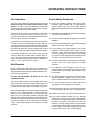
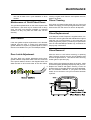
Owners &
Installation
In-built Fireplaces
Ontario / Vancouver
Manual
Model: I2101
Model: I3101
PLEASE KEEP THESE INSTRUCTIONS
FOR FUTURE REFERENCE
Head Office - Australia
54 Boundary Rd. Braeside
P.O. Box 553
Mordialloc 3195
Ph. (03) 9586-7777
Fax. (03) 9586-2980
Head Office - New Zealand
1-37 Mt Wellington Hwy.Panmure,
P.O. Box 14349
Auckland 6.
Ph. (9) 570-9009
Fax. (9) 527-1294
Thank-you for purchasing a
MASPORT FIREPLACE PRODUCT.
The pride of workmanship that goes into each of our products will give you years of trouble-free
enjoyment. Should you have any questions about your product that are not covered in this
manual, please contact the MASPORT DEALER in your area.
Keep those MASPORT FIRES burning.
SAFETY NOTE: If this in-built fireplace is not properly installed, a house fire may result. For your
safety, follow the installation instructions, contact local building or fire officials about restrictions
and installation inspection requirements in your area.
2
Masport In-built Fireplaces
TABLE OF CONTENTS
THE MASPORT IN-BUILT FIREPLACE
& HEARTH HEATER
Page
INSTALLATION
In-built fireplace Safety Labels
Ontario (I2101M) ................................ 4
Vancouver (I3101L) ............................ 5
Before Installing Your Unit ....................... 6
Chimney Specifications ...................... 6
Installation in "0" Clearance Factory
Built Fireplace ................................. 6
Fireplace Specifications ..................... 6
Masonry & Factory Built Clearances .. 7
Installing your In-built fireplace ................. 8
Convection Grill Installation ................ 8
Optional Flue Connector Kit ............... 8
Flue Connector Bracket ..................... 8
A) Into a Masonry Fireplace .............. 9
B) Into a Factory Built Fireplace ........ 9
C) All Units - Faceplate & Trim ........ 10
Floor Protection ...................................... 10
Firebrick Assembly ................................. 10
Fan / Blower ........................................... 11
Door Handle ........................................... 11
Brick Flue Baffle & Secondary Air Tube
Installation .............................................. 12
Vancouver (I3101) ............................ 12
Ontario (I2101) ................................. 13
Page
MAINTENANCE
Creosote ................................................. 16
Removal for Cleaning ....................... 16
Ways to Prevent and Keep Unit
Free of Creosote ............................. 16
Maintenance of Gold Plated Door .......... 17
Door Gasket ........................................... 17
Door Latch Adjustment ........................... 17
Glass Cleaning ....................................... 17
Glass Replacement ................................ 17
Glass Removal ....................................... 17
PARTS
Parts List ................................................ 18
WARRANTY
Warranty ................................................. 23
OPERATING INSTRUCTIONS
Draft Control ........................................... 13
First Fire ................................................. 14
Fan / Blower Operation .......................... 15
Ash Disposal .......................................... 15
Safety Guidelines ................................... 15
Masport In-built Fireplaces
3
C
D
E
G
INSTALL ONLY ON A NON-COMBUSTIBLE HEARTH RAISED (F) 1.5IN / 38MM
ABOVE AN ADJACENT COMBUSTIBLE FLOOR. COMBUSTIBLE FLOOR MUST BE
PROTECTED BY NON-COMBUSTIBLE MATERIAL EXTENDING (E) 16 IN / 405 MM
TO FRONT AND (G) 8 IN / 205 MM TO SIDES FROM FUEL DOOR.
F
COMPONENTS REQUIRED FOR INSTALLATION: 6IN / 150MM STAINLESS STEEL LINER.
OPTIONAL COMPONENT: FAN, ELECTRICAL RATING: VOLTS 115, 60 HZ, 0.6 AMPS
DO NOT REMOVE BRICKS OR MORTAR IN MASONRY FIREPLACE. FOR USE WITH SOLID WOOD FUEL ONLY. DO NOT USE GRATE OR ELEVATE
FIRE. BUILD WOOD FIRE DIRECTLY ON HEARTH. OPERATE WITH FEED DOOR CLOSED, OPEN TO FEED FIRE ONLY. REPLACE GLASS ONLY WITH
CERAMIC GLASS (5MM). INSPECT AND CLEAN CHIMNEY FREQUENTLY. UNDER CERTAIN CONDITIONS OF USE CREOSOTE BUILDUP MAY OCCUR
RAPIDLY. DO NOT OVERFIRE, IF INSERT GLOWS YOU ARE OVER-FIRING.
Date:
Nov. 1, 2000
Filename:
908-331
Size:
Above artwork is to be Printed at 80%.
Colour:
Black on grey, except for what is highlighted in yellow
will be red on grey
November 14, 2001: Updated to new serial number system. Otherwise no other changes to artwork.
HOT WHILE IN OPERATION
DO NOT TOUCH. KEEP CHILDREN,
CLOTHING AND FURNITURE AWAY.
CONTACT MAY CAUSE SKIN BURNS.
READ ABOVE INSTRUCTIONS.
Manufactured By:
FIREPLACE PRODUCTS INTERNATIONAL LTD.
6988 VENTURE ST., DELTA, BC V4G 1H4
MADE IN CANADA
908-331 rev. 11/00
Apr May
July Aug Sept Oct
June
2001
2002
2003
Nov
Dec
(Duplicate Serial #) 105
B
A
Feb Mar
DATE OF
MANUFACTURE
10 in / 255 mm
17 in / 510 mm
10.25 in / 260 mm
8 in / 205 mm
SIGNATURE
A)
B)
C
D)
Jan
CERTIFIED TO COMPLY WITH
JULY 1990, PARTICULATE
EMISSION STANDARDS.
MANUFACTURED BY FPI LTD.
Masport In-built Fireplaces
ADJACENT SIDEWALL
MANTLE
TOP FACING
SIDE FACING
ADJACENT SIDEWALL
MINIMUM CLEARANCES TO COMBUSTIBLE MATERIALS (MEASURED FROM INSERT BODY)
UNITED STATES ENVIRONMENTAL
PROTECTION AGENCY
CAUTION
INSTALLATION
105
This is a copy of the label that accompanies
each Ontario In-built Fireplace. We have
printed a copy of the contents here for your
review.
NOTE: Masport units are constantly being
improved. Check the label on the unit and if
there is a difference, the label on the unit is the
correct one.
4
LISTED FACTORY BUILT FIREPLACE INSERT
DO NOT REMOVE THIS LABEL
CERTIFIED FOR USE IN CANADA AND U.S.A.
MODEL: I2100M
TESTED TO: ULC S628-M91 / UL 1482-1991
REPORT NO. 632-323500
(OCT.1993)
INSTALL AND USE ONLY IN ACCORDANCE WITH THE MANUFACTURER'S INSTALLATION AND OPERATING INSTRUCTIONS. INSTALL AND USE
ONLY IN MASONRY FIREPLACE OR FACTORY BUILT FIREPLACE. CONTACT LOCAL BUILDING OR FIRE OFFICIALS ABOUT RESTRICTIONS AND
INSTALLATION INSPECTION IN YOUR AREA.
106
This is a copy of the label that accompanies
each Vancouver In-built Fireplace. We have
printed a copy of the contents here for your
review.
NOTE: Masport units are constantly being
improved. Check the label on the unit and if
there is a difference, the label on the unit is the
correct one.
Masport In-built Fireplaces
DO NOT REMOVE THIS LABEL
LISTED FACTORY BUILT FIREPLACE INSERT
CERTIFIED FOR USE IN CANADA AND U.S.A.
MODEL: I3100L
TESTED TO: ULC S628-M91 / UL 1482-1991
REPORT NO. 632-323500
(MAR.1994)
CAUTION
ADJACENT SIDEWALL
MANTLE
TOP FACING
SIDE FACING
A)
B)
C)
D)
13"(330mm)
19"(480 mm)
18"(455 mm)
6.5"(165mm)
ADJACENT SIDEWALL
Minimum Clearances to Combustibles
(Measured from insert body)
B
C
D
A
G
E
INSTALL ONLY ON A NON-COMBUSTIBLE HEARTH RAISED (F) 1.5"
(38mm) ABOVE AN ADJACENT COMBUSTIBLE FLOOR. COMBUSTIBLE
FLOOR MUST BE PROTECTED BY NON-COMBUSTIBLE MATERIAL
EXTENDING (E) 16" (405mm) TO FRONT AND (G) 8" (205mm) TO SIDES
FROM FUEL DOOR.
F
COMPONENTS REQUIRED FOR INSTALLATION: 6" (150mm) STAINLESS STEEL LINER.
OPTIONAL COMPONENT: FAN, ELECTRICAL RATING: VOLTS 115, 60 HZ, 0.6 AMPS
DO NOT REMOVE BRICKS OR MORTAR IN MASONRY FIREPLACE. FOR USE WITH SOLID WOOD FUEL ONLY. DO
NOT USE GRATE OR ELEVATE FIRE. BUILD WOOD FIRE DIRECTLY ON HEARTH. OPERATE WITH FEED DOOR
CLOSED, OPEN TO FEED FIRE ONLY. REPLACE GLASS ONLY WITH CERAMIC GLASS (5mm). INSPECT AND
CLEAN CHIMNEY FREQUENTLY. UNDER CERTAIN CONDITIONS OF USE CREOSOTE BUILDUP MAY OCCUR
RAPIDLY. DO NOT OVERFIRE, IF INSERT GLOWS YOU ARE OVER-FIRING.
DATE OF MANUFACTURE
908-343 rev. 05/00
2001 2002 2003
JAN
FEB
MAR
APR
MAY
JUN
JUL
AUG
Manufactured by:
REGENCY INDUSTRIES LTD.
6988 Venture Street
Delta, BC
V4G 1H4
MADE IN CANADA
SEPT OCT
NOV
DEC
HOT WHILE IN OPERATION
DO NOT TOUCH. KEEP
CHILDREN, CLOTHING
AND FURNITURE AWAY.
CONTACT MAY CAUSE
SKIN BURNS. READ ABOVE
INSTRUCTIONS.
UNITED STATES
ENVIRONMENTAL PROTECTION
AGENCY CERTIFIED TO COMPLY
WITH JULY 1990, PARTICULATE
EMISSION STANDARDS.
5
INSTALLATION
(Duplicate Serial #)
Install and use only in accordance with the manufactuerer's installation and operating instructions. Install and use only in masonry
fireplace or factory built fireplace. Contact local building or fire officials about restrictions and installation inspection in your area.
INSTALLATION
Masport In-built Fireplaces are constructed with the
highest quality materials and assembled under strict
quality control procedures that insure years of trouble
free and reliable performance.
It is important that you read this manual thoroughly and
fully understand the safe installation and operating
procedures. The more you understand the way your
Masport In-built Fireplace operates, the more enjoyment
you will experience from knowing that your unit is
operating at peak performance.
Before Installing Your
In-built Fireplace
1) Read all instructions before installing and using your
in-built fireplace. Install and use only in accordance
with manufacturer’s installation and operating
instructions.
2) Check your local building codes - Building Inspection
Department. You may require a permit before
installing your in-built fireplace. Be aware that local
codes and regulations may override some items in
the manual.
WARNING: Careless installation is the major
cause of safety hazard. Check all local building
and safety codes before installation of unit.
3) Notify your home insurance company that you plan
to install a in-built fireplace or hearth heater.
4) Your in-built fireplace is heavy and requires two or
more people to move it safely. The in-built fireplace
can be badly damaged by mishandling.
5) If your existing fireplace damper control will become
inaccessible once you have installed your Masport
In-built Fireplace, you should either remove or secure
it in the open position.
6) Inspect your fireplace and chimney prior to installing
your in-built fireplace to determine that it is free from
cracks, loose mortar or other signs of damage. If
repairs are required, they should be completed
before installing your in-built fireplace. Do not
remove bricks or mortar from your masonry fireplace.
7) Do not connect the in-built fireplace to a chimney
system servicing another appliance or an air
distribution duct.
6
Chimney Specifications
Before installing, check and clean your chimney system
thoroughly. If in doubt about its condition, seek expert
advice. Your Masport In-built fireplace is designed for
installation into a masonry fireplace that is constructed
in accordance with the requirements of "The Standard
for Chimneys, Fireplaces, Vents, and Solid Fuel Burning
Appliance", N.F.P.A. 211, AS 4013 , and NZS 7402 or
the applicable local code requirements.
Masport In-built Fireplaces are designed with a 6"
(150mm) flue but a 7"(180mm) or 8"(200mm) flue liner
or flue connector may be used.
Installation in "0" Clearance Factory
Built Fireplace
The Ontario In-built Fireplace (I2101M) and Vancouver
In-built Fireplace (I3101L) have been tested and
approved to be vented into any approved "0" clearance
Factory Built Fireplace that will accommodate your
Masport unit.
IMPORTANT: If the Ontario or Vancouver unit is
being installed into a factory built fireplace, check
that factory variations of the "0" clearance fireplace
will allow the in-built fireplace to physically fit into
the firebox.
If the factory built fireplace height is too low for your
in-built fireplace, you may remove the smoke shelf,
baffle plate and damper plate from the factory built
fireplace as long as these items are saved and are
re-installed in the event that the in-built fireplace is
removed.
Fireplace Specifications
Your fireplace opening requires the following minimum
sizes:
Height Width
Depth
Ontario (I2101M)
546mm 635mm 432mm
Vancouver (I3101L)
635mm 711mm 432mm
Two faceplates are available to seal the fireplace opening:
Ontario (I2101M)
Standard: 1016mmW x 762mmH
Oversize:1219mmW x 838mmH
Vancouver (I3101L) Standard:1118mmW x 813mmH
Oversize:1270mmW x 876mmH
Masport In-built Fireplaces
INSTALLATION
Masonry and Factory Built Fireplace Clearances
The minimum required clearances to combustible materials when installed into a masonry or factory built fireplace
are listed below.
Unit
Adjacent
Side Wall
(to Side)
A
Mantle
(to Top)
B
Top
Facing
(to Top)
C
Side
Facing
(to Side)
D
Minimum
Hearth
Extension*
E
Minimum
Hearth
Elevation*
F
Minimum
Hearth Side
Extension
G
Ontario
In-built (I2101M) 10"/530mm
17"/430mm
10.25"/260mm
8"/203mm
16"/406mm
1.5"/38mm
8"/205mm
Vancouver
In-built (I3101L)
19"/480mm
18"/455mm
6.5"/165mm
16"/406mm
1.5"/38mm
8"/205mm
13"/330mm
Side and Top facing is a maximum of 1.5"(38mm) thick.
Floor protection must non-combustible, insulative material with an R value of 1.1 or greater.
*
If the hearth extension is flush with the floor (F) it must extend 19.5"(495mm) in front of the body face (E).
Note: Hearth Extension Width (G) is measured from edge of fuel door to side of hearth.
Clearance diagram for installations
Masport In-built Fireplaces
7
INSTALLATION
Installing Your In-built Fireplace
Optional Flue Connector Kit
Your in-built fireplace is very heavy and will require two
or three people to move it into position. The in-built
fireplace can be made a little lighter by removing the cast
iron door by opening it and lifting it off its hinges. Be sure
to protect your hearth extension with a heavy blanket or
carpet scrap during the installation.
The optional Flue Connector Kit, Part # 846-527, may be
used to produce a secure connection between your flue
connector and the in-built fireplace collar. Detailed
installation instructions are included with the kit.
Convection Grills
The convection grills are installed before the unit is
positioned inside the fireplace.
Position the grill on the inside bodyface side and fasten
using the bolts, washers and nuts provided (2 per side)
as shown in the diagrams.
Flue Connector Bracket
Package contains: 3 brackets and 6 screws.
These brackets are to be used to hold the flue liner
(not supplied) to the in-built fireplace and keep the
connection. The brackets are screwed into the top of
the in-built fireplace in the pre-punched holes and
then screwed into the flue liner.
View from Rear
of In-built
Fireplace
Note: The grill has a front and rear, the holes on the
front side have rounded edges and the rear
holes have flat edges.
8
Masport In-built Fireplaces
INSTALLATION
A) Into a Masonry Fireplace
B) Into a Factory Built Fireplace
The in-built fireplace must be installed as per the
requirements of your local inspection authority. Three
methods of flue connection are acceptable in most
areas, these include:
1) When installed in a factory built fireplace, a full
stainless steel rigid or flexible flue liner is mandatory,
for both safety and performance purposes. When
a flue or liner is in use, the in-built fireplace is able
to breathe better by allowing a greater draft to be
created. The greater draft can decrease problems
such as, difficult start-ups, smoking out the door,
and dirty glass.
1) Positive flue connection, where a large blocking
plate and a short connector pipe is used.
2) Direct flue connection, where a smaller blocking
plate and a connector pipe to the first flue liner tile
is used.
3) Full flue liner, where a stainless steel rigid or flexible
liner pipe is routed from the in-built fireplace outlet
collar to the top of the chimney.
2) In order to position the flue liner, the existing rain
cap must be removed from your chimney system. In
most cases the flue damper should also be removed
to allow passage of the liner.
3) In most cases opening the existing spark screens
fully should give enough room for the in-built fireplace
installation. If it does not, remove and store.
4) If the floor of your fireplace is below the level of the
fireplace opening, adjust the in-built fireplace's
levelling bolts to accommodate the difference. When
additional shimming is required, use noncombustible masonry or steel shims.
5) Measure approximately the alignment of the flue
liner with the position of the smoke outlet hole on the
in-built fireplace to check for possible offset. If an
offset is required, use a proper stainless steel unit
1) Positive Flue 2) Direct Flue 3) Full Flue Liner
available with the chimney liner.
Connection
Connection
(No Cleanout
with Cleanout
with Cleanout
Required)
6) Once the above items have been checked, slide
your in-built fireplace into position after first
Masport highly recommends the use of a full liner as the
positioning the flue liner and offset if required. (Resafest installation and provides the most optimum
install raincap at completion of installation).
performance. Your retailer should be able to help you
decide which system would be the best for your
application.
Note: A clean-out door is sometimes required, by
your inspector, to be installed when either
the Positive flue connection or Direct flue
connection method is used.
The use of one of the connection methods listed on this
page not only increases the safety of your in-built
fireplace by directing the hot gases up the flue, but will
also help increase the unit's efficiency and decrease
creosote deposits in the chimney.
When a connected flue or liner is in use, the in-built
fireplace is able to “breathe” better by allowing a greater
draft to be created. The greater draft can decrease
problems such as, difficult start-ups, smoking out the
door, and dirty glass.
Masport In-built Fireplaces
9
INSTALLATION
C) ALL UNITS
Faceplate and Trim
Prior to sliding your insert into its final position and
attaching the connector or liner pipe, the faceplate must
be installed as follows:
1) Slide the spring nuts (supplied) over the slots in the
insert’s side convection panels (the spring nuts may
need to be squeezed with a pair of pliers first, to help
them stay in position).
2) Screw the side faceplate panels, (item A in the
diagram) one to each side.
3) Using the top panel (item B in the diagram) as a
gauge, check that the side panels are within
approximately 1/4" of the overall width. If the
difference is greater than this, use the
supplied washers to attain the required
width.
4) The unit may now be slid into final position and
attached to the connection system.
5) Once connection is made, the insulation strips
should be installed between the insert faceplates
and the fireplace face.
6) The faceplate top may now be installed (with
insulation strip behind) by aligning its brackets with
the top flange on the side shields and the angle iron
bar on the insert top.
7) The faceplate trim may be installed to the edge of
the faceplate at this time. To permanently mount the
trim, drill two 5/32" diameter holes through the trim
and side panels and screw the trim to the panels
using the gold plated screws provided.
Note: It may be easier to install the insulation,
faceplate top and faceplate trim with the unit pulled
slightly away from the fireplace face. If this is done,
be very careful not to disturb the connector when
shifting the unit to its final position.
8) Now that your insert is installed, check once more
that all the clearances from the unit to any combustible
materials are correct as listed earlier.
.
Floor Protection
Please check to ensure that your floor protection and
hearth will meet the standards for clearance to
combustibles. Your hearth extension must be made
from a non-combustible material.
Firebrick Assembly
Firebrick is included to extend the life of your in-built
fireplace and radiate heat more evenly.
Check to see that all firebricks are in
their correct positions and have
not become misaligned
during shipping.
Ontario
In-built Fireplace
(I2101M)
Diagram 1
10
Vancouver
In-built Fireplace
(I3101L)
Masport In-built Fireplaces
INSTALLATION
Fan/Blower
Your fan should only be installed once the unit is in place
in order to prevent any damage to the fan. To attach,
follow the instructions provided with the fan. Make sure
to install the rubber grommet to the fan housing before
it is installed on the insert.
1) Remove the protective covering from the brass
trim on the fan.
2) Align the fan support with the offset clip on the
bottom of the ashlip.
3) Slide the supports into the clips. The tension holding
the clips in place may be adjusted by increasing or
decreasing the offset spacing of the clips.
4) Ensure that the power cord is not in contact with any
hot stove surfaces.
5) Push the Masport logo plate into the two holes in the
front bottom left corner of the fan.
Do not turn fan ON until your insert has reached
operating temperature or at least 30 minutes after
starting fire.
CAUTION: Label all wires prior to disconnection
when servicing controls. Wiring errors can cause
improper and dangerous operation.
o
erm
Th
itch
Sw
or
ns
Se
WARNING:
Electrical Grounding Instructions
This appliance is equipped with a three pronged (grounding) plug for your protection against shock hazard and
should be plugged directly into a properly grounded
three-prong receptacle. Do not cut or remove the grounding prong from this plug.
Caution: Ensure that the wires do not touch any hot
surfaces and are away from sharp edges.
Blower/Fan Wiring Diagram
Door Handle
Attach spring handle by rotating counter clockwise onto rod. Ensure that the rod
fits into the entire length of the spring handle.
Masport In-built Fireplaces
11
INSTALLATION
Brick Flue Baffle & Secondary Air
Tube Installation
The flue baffle system located in the upper area of the
firebox is removable to make cleaning your chimney
system easier. The brick baffles must be installed prior
to your first fire. Smoke spillage and draft problems
may occur if the baffles are improperly positioned.
Check the position of the brick baffles on a regular basis
as they can be dislodged if too much fuel is forced into
the firebox.
The Vancouver units (F3100L) are shipped with one of
the secondary air tubes loose inside the firebox. This
needs to be installed after the brick baffle are installed.
Follow the directions below.
Vancouver In-built Fireplace I3101L
The unit arrives with the third air tube (from the front)
and the 2 baffle bricks on the floor of the firebox. The
baffle bricks are positioned first and then the air tube is
installed.
1) Slide the left baffle brick over the front two air tubes
and then slide it back over the rear air tube. Diagrams
5 and 6.
Diagram 5: Side View
3) Important: push both baffle bricks so they are
tight against the side walls. Diagram 8.
Diagram 8: Front View
4) Install the third (from the front) air tube into the
holes on the side channels. The notch goes on the
right hand side with the air holes facing forward
toward the door opening. If the tube will not slide in
easily, simply use a pair of vise grips or pliers and
tap it into place with a hammer. A tighter fit will
ensure the tube will not move when the unit is
burning. Diagrams 9 and 10.
Diagram 9:
Side View
Install Air Tube
Diagram 6: Side View
2) Tilt the left baffle brick up on top of the side channel
and it will leave enough room to position the right
baffle brick in the same manner as Step 1) above.
Then reposition the left baffle brick flat on the air
tubes. Diagram 7.
Diagram 10: Air Tube Installation
Note: When cleaning the chimney reverse the above
procedures, removing the air tube and baffle
bricks and then replace them when cleaning
is completed.
Diagram 7: Front View
12
Masport In-built Fireplaces
INSTALLATION
Ontario In-built Fireplace (I2101M)
The unit arrives with the 2 baffle bricks on the floor of the
firebox.
1) If all 3 air tubes are installed continue on to Step 2),
if not, follow the instructions below. Install the air
tube into the holes in the side channels. The notch
goes on the right hand side with the air holes facing
toward the door. Slide the tube into the left hand
side, as far as possible and then bring it back into
the hole on the right hand side until it locks into
position. If the tube will not slide in easily, simply use
a pair of vise grips or pliers vise grips and tap it into
place with a hammer. A tighter fit will ensure the tube
will not move when the unit is burning. See the
diagram for the Montreal air tube installation (page
15), though there are only three air tubes in the
Vancouver units.
2) Slide the left baffle brick over the air tubes from the
front, then push it to the back. Diagrams 11 and 12.
Diagram 11: Side View
Diagram 12: Side View
3) Tilt the left baffle brick up on top of the side channel
and it will leave enough room to position the right
baffle brick in the same manner as Step 1) above.
Then reposition the left baffle brick flat on the air
tubes. Diagram 13.
stove, this should leave sufficient access to
the flue. If it is not enough space then
remove the middle air tube (reverse the
procedure in step 1) above), and baffle bricks
and then replace everything when cleaning
is completed.
Diagram 14: Front View
Draft Control
Before establishing your first fire, it is important that your
fully understand the operation of you draft control. The
draft rod is on the left side of the In-built fireplaces and
it controls the intensity of the fire by increasing or
decreasing the amount of air allowed into the firebox. To
increase your draft - pull open, and to decrease - push
closed.
Pull Open
Push Closed
As well as a primary and glass wash air system, the unit
has a full secondary draft system that allows air to the
induction ports at the top of the firebox, just below the
flue baffle.
WARNING: To build a fire in ignorance or to disregard
the information contained in this section can cause
serious permanent damage to the unit and void your
warranty.
Diagram 13: Front View
4) Important: push both baffle bricks so they are
tight against the side walls. Diagram 14.
Note: When getting the chimney cleaned, push the
brick baffles forward toward the front of the
Masport In-built Fireplaces
13
OPERATING INSTRUCTIONS
First Fire
When your installation is completed and inspected, you
are ready for your first fire.
1) Open draft control fully.
2) Open firebox door and build a small fire using paper
and dry kindling, wait a few minutes for a good
updraft in the flue to establish the fire. Leaving the
door slightly open will help your fire start more
rapidly.
9) During the first few hours it may be more difficult to
start the fire. As you dry out your fire brick and your
masonry flue (if applicable), your draft will increase.
10) For those units installed at higher elevations or into
sub-standard masonry fireplaces, drafting problems
may occur. Consult an experienced dealer or mason
on methods of increasing your draft.
11) Some cracking and popping noises may be
experienced during the heating up process. These
noises will be minimal when your unit reaches
temperature.
CAUTION: Never leave unit unattended if door is
left open. This procedure is for fire start-up
only, as unit may over-heat if door is left open for
too long.
12) Before opening your door to reload, open draft fully
for approximately 10 to 15 seconds until fire has
been re-established. This will minimize any smoking.
3) With the draft still in the fully open position, add two
or three seasoned logs to your fire. Form a trench
in the ash bed to allow air to reach the rear of the
firebox prior to closing the door.
13) All fuel burning appliances consume oxygen during
operation. It is important that you supply a source
of fresh air to your unit while burning. A slightly
opened window is sufficient for this purpose.
4) After about 15 to 20 minutes, when your wood has
begun to burn strongly, adjust your draft control
down to keep the fire at a moderate level.
WARNING: Never build a roaring fire in a cold
stove. Always warm your stove up slowly!
CAUTION: If the body of your unit (or in the
H2100M flue baffle) starts to glow you are
overfiring. Stop loading fuel immediately and
close the draft control until the glow has
completely subsided.
5) Once a bed of coals has been established, you may
adjust the draft control to a low setting to operate the
unit in its most efficient mode.
14) Green or wet wood is not recommended for your
unit. If you must add wet or green fuel, open the draft
control fully until all moisture has been dispersed by
the intense fire. Once all moisture has been removed,
the draft control may be adjusted to maintain the
fire.
6) During the first couple of hours, keep the combustion
rate at a moderate level and avoid a large fire until
the paint is cured. Only then can you operate the inbuilt fireplace at its maximum setting, and only after
the metal has been warmed.
7) For the first few hours, the in-built fireplace will give
off an odor from the paint. This is to be expected as
the high temperature paint becomes seasoned.
Windows and/or doors should be left open to provide
adequate ventilation while this temporary condition
exists. Burning the in-built fireplace at a very high
temperature the first few times may damage the
paint. Burn fires at a moderate level the first few
days.
15) If you have been burning your in-built fireplace on a
low draft, use caution when opening the door. After
opening the damper, open the door a crack, and
allow the fire to adjust before fully opening the door.
16) The controls of your unit should not be altered to
increase firing for any reason.
8) Do not place anything on the in-built fireplace top
during the curing process. This may result in damage
to your paint finish.
14
Masport In-built Fireplaces
OPERATING INSTRUCTIONS
Fan Operation
Some Safety Guidelines
The fan is to be operated only with the draft control rod
pulled out at least 1/2"(13mm) from the fully closed
position. The fan is not to be operated when the draft
control rod is in the closed position (pushed in). The fully
closed position is the low burn setting.
1) Never use gasoline, gasoline type lantern fuels,
kerosene, charcoal lighter fuel, or similar liquids to
start or ‘freshen up’ a fire in your heater. Keep all
such liquids well away from the heater while it is in
use.
The fan unit must not be turned on until a fire has been
burning for at least 30 minutes and the unit is hot
enough. As well, after each fuel loading the fan must be
shut off until 30 minutes has elapsed.
2) Keep the door closed during operation and maintain
all seals in good condition.
To operate fan automatically, push switch on side of fan
housing to "Auto" and second switch to either "High" or
"Low" for fan speed. The automatic temperature sensor
will engage the blower when the unit is at temperature
and will shut off the blower once the fire has gone out and
the unit has cooled to below a useful heat output range.
To manually operate the fan system, push the first
switch to "Man" and second switch to either "high" or
"Low". This will bypass the sensing device and allow full
control of the fan. Switching from "Auto" to "Manual" or
"High" to "Low" may be done at any time.
3) Do not burn large quantities of paper in your in-built
fireplace.
4) If you have smoke detectors, prevent smoke spillage
as this may set off a false alarm.
5) Do not overfire your in-built fireplace. If the in-built
fireplace or its flue baffle begin to glow, you are
overfiring. Stop adding fuel and close the draft
control. Overfiring can cause extensive damage to
your stove including warpage and premature steel
corrosion. Overfiring will void your warranty.
Ash Disposal
6) Do not permit creosote or soot buildup in the chimney
system. Check and clean chimney at regular
intervals.
During constant use, ashes should be removed every
few days. Please take care to prevent the build-up of ash
around the start-up air housing located inside the firebox,
under the loading door lip.
7) Your Masport In-built Fireplace can be very hot.
You may be seriously burned if you touch the in-built
fireplace while it is operating. Warn children of the
burn hazard.
DO NOT ALLOW ASHES TO BUILD UP TO THE
LOADING DOORS.
8) The in-built fireplace consumes air while operating,
provide adequate ventilation with an air duct or
open a window while the in-built fireplace is in use.
Only remove ashes when the fire has died down. Even
then, expect to find a few hot embers. Always leave 1 to
2 inches of ash in the bottom of the firebox. This helps
in easier starting and a more uniform burn of your fire.
9) Do not use grates, irons or other methods for
supporting fuel. Burn directly on the bricks.
Ashes should be placed in a metal container with a tight
fitting lid. The closed container of ashes should be
placed on a noncombustible floor or on the ground, well
away from all combustible materials, pending final
disposal. If the ashes are disposed of by burial in soil or
otherwise locally dispersed, they should be retained in
the closed container until all cinders have thoroughly
cooled. Other waste should not be placed in the ash
container.
Masport In-built Fireplaces
10) Open the draft control fully for 10 to 15 seconds prior
to slowly opening the door when refuelling the fire.
11) Do not connect your unit to any air distribution duct.
12) Your in-built fireplace should burn dry, standard
firewood only. The use of “mill ends” is discouraged
as this fuel can easily overheat your in-built fireplace.
Evidence of excessive overheating will void your
warranty. As well, a large portion of sawmill waste
is chemically treated lumber, which is illegal to burn
in many areas. Chemically treated fire logs also
must not be burned in your in-built fireplace.
15
MAINTENANCE
2) Call the Fire Department
13) Do not store any fuel closer than 2 feet from your
unit.
Ways to Prevent and
14) Do not burn salt drift wood as it will corrode your unit Keep Unit Free of Creosote
and void the warranty.
15) Do not operate the unit if the glass is broken or
missing. Do not operate the unit if the gasketing is
worn out and not sealing the door or the glass.
It is very important to carefully maintain your in-built
fireplace, including burning seasoned wood and
maintaining a clean stove and chimney system. Have
the chimney cleaned before the burning season and as
necessary during the season, as creosote deposits may
build up rapidly. Moving parts of your in-built fireplace
require no lubrication.
Creosote
When wood is burned slowly, it produces tar and other
organic vapors, which form creosote when combined
with moisture. The creosote vapors condense in the
relatively cool chimney flue of a slow-burning fire. As a
result, creosote residue accumulates on the flue lining.
When ignited, this creosote can make an extremely hot
fire.
1) Burn in-built fireplace with draft control wide open
for about 15 minutes every morning during burning
season. This helps to prevent creosote deposits
within the heating system.
2) Burn in-built fireplace with draft control wide open
for about 10 - 15 minutes every time you add fresh
wood. This allows the wood to achieve the charcoal
stage faster and burns up any wood vapors which
might otherwise be deposited within the system.
3) Only burn seasoned wood! Avoid burning wet or
green wood. Seasoned wood has been dried at
least one year.
4) A small hot fire is preferable to a large smouldering
one that can deposit creosote within the system.
5) Check the chimney at least twice a month during the
burning season for creosote build-up.
6) Have chimney system and unit cleaned by competent
chimney sweeps twice a year during the first year of
Removal for Cleaning etc.
Removal of your in-built fireplace for cleaning purposes
is usually not required if a proper installation has been
done. In the event that removal is required, be sure not
to damage any parts needed for re-installation. In most
cases removal and replacement of the baffle system
should allow full access for cleaning.
WARNING: Things to remember in case
of chimney fire:
1) Close draft control
16
Masport In-built Fireplaces
MAINTENANCE
use and at least once a year thereafter or when
needed.
Maintenance of Gold-Plated Doors
The gold electroplated finish on the doors requires little
maintenance, and need only be cleaned with a damp
cloth. DO NOT use abrasive materials or chemical
cleaners, as they may harm the finish and void the
warranty.
Door Gasket
If the door gasket requires replacement, 7/8" diameter
material must be used. A proper high temperature
gasket adhesive is required. A gasket repair kit, Part #
846-570 is available from your local Masport dealer.
causing a tighter seal. Remove and replace the nuts,
washer as shown.
Glass Cleaning
Only clean your glass window when it is cool. Your local
retailer can supply you with special glass cleaner if plain
water and a soft cloth does not remove all deposits.
Glass Replacement
Your Masport In-built Fireplace is supplied with 5 mm.
Neoceram ceramic glass that will withstand the highest
heat that your unit will produce. In the event that you
break your glass by impact - purchase your replacement
from an authorized Masport dealer only, and follow our
step-by-step instructions.
Glass Removal
Door Latch Adjustment
The door latch may require adjustment as the door
gasket material compresses after a few fires. Removal
of the spacer washer, shown in the diagram below, will
allow the latch to be moved closer to the door frame,
Masport In-built Fireplaces
Allow the stove to cool before removing or replacing
glass. Remove the door from the in-built fireplace and
remove the glass retainer. Use caution when removing
broken glass to prevent injury.
When placing the replacement glass in the door, make
sure that the glass gasketing will properly seal your unit.
Replace the retainer and tighten securely, but do not
spanner down on the glass as this may cause breakage.
Do not substitute materials. If your glass door does
break, do not continue to use your unit until it has been
replaced.
17
REPLACEMENT / SPARE PARTS LIST
Ontario - Medium Inbuilt Fireplace I2101 - Main Assembly
2)
4)
5)
6)
7)
9)
16)
17)
19)
20)
23
Part #
Part #
Description
Australia New Zealand
846-916
Large Door Assy - Black
846-910
Large Door Assy - Gold
846-304
Glass - Large
936-243
560087 7/8" Glass Gasket
846-920
560202 Glass Retainer Clips (Set)
*
Screw - 1/4 - 20 x 3/8"
948-172/P
Large Glass Retainer
846-973
Door Handle Assembly
846-570
560203 Door Gasket Kit
846-918
560204 Hinge Cap - Gold (2/set)
948-101
560208 Spring Handle - Large
948-102
Spring Handle - Small
820-235
Flue Brackets
36) 033-953
37) 033-955
42) 163-930
163-932
43) *
44) *
45) *
18
25)
26)
27)
28)
29)
30)
Part #
Australia
142-920
910-714
910-155/P
910-142
910-140
910-138
*
Part #
Description
New Zealand
Complete Fan Assy
560061 Power Cord (240 V)
560023 Fan Motor (240 V)
Fan Thermodisc
560036 Fan High/Off/Low Switch (3-way)
Fan Auto/Manual Switch
Fan Housing
948-217
Logo - Masport
908-047
Manual
*Not available as a replacement part.
Air Tube - 3/4" each (Qty. 3)
Baffle (2/set)
Convection Grill - Black
Convection Grill - Gold
Hex Nut 10-24 Zinc Coated
Washer #10 Flat
Carriage Bolt #10-24 x 3/4"
Masport In-built Fireplaces
REPLACEMENT / SPARE PARTS LIST
Ontario - Medium Inbuilt Fireplace I2101 - Accessories
Part #
Australia
Part #
Description
New Zealand
70) 902-111
76) 802-152
78) 802-143
Bricks
Brick: 32mm x 114mm x 229mm
Brick: 32mm x 51mm x 229mm
Brick: 32mm x 57mm x 57mm
140-911
285) 143-161
286) 143-158
287) 143-160
288) *
289) *
Faceplate & Trim - Regular
Trim - Right - Regular
Trim - Top - Regular
Trim - Left - Regular
Faceplate - Side - Regular
Faceplate - Top - Regular
140-913
295) 143-164
296) 143-162
297) 143-163
298) *
299) *
Faceplate & Trim - Oversize
Trim - Right - Oversize
Trim - Top - Oversize
Trim - Left - Oversize
Faceplate - Side - Oversize
Faceplate - Top - Oversize
Part #
Australia
846-532
836-300
846-531
Part #
Description
New Zealand
Trim Clips
Yellow Insulation 1219mm x 102mm
Faceplate Hardware Pkg.
*Not available as a replacement part.
Masport In-built Fireplaces
19
REPLACEMENT / SPARE PARTS LIST
Vancouver - Large Inbuilt Fireplace I3101 - Main Assembly
Part #
Australia
1)
3)
4)
5)
6)
7)
9)
16)
17)
19)
20)
23)
35)
36)
38)
846-916
846-910
846-304
936-243
846-920
*
948-172/P
846-973
846-570
846-918
948-101
948-102
820-235
063-954
063-953
063-955
42) 163-930
163-932
43) *
44) *
45) *
20
Part #
Description
New Zealand
560087
560202
560203
560204
560208
Large Door Assy - Black
Large Door Assy - Gold
Glass - Large
7/8" Glass Gasket
Glass Retainer Clips (set)
Screw - 1/4 - 20 x 3/8"
Large Glass Retainer
Door Handle Assembly
Door Gasket Kit
Hinge Cap - Gold (2/set)
Spring Handle - Large
Spring Handle - Small
Flue Brackets
Air Tube - 1" (Qty. 1)
Air Tube - 3/4" (Qty. 3)
Baffle
Part #
Australia
25)
26)
27)
28)
29)
30)
Part #
Description
New Zealand
163-920
910-714 560061
910-155/P 560023
910-142
910-140 560036
910-138
*
Complete Fan Assy
Power Cord (240 V)
Fan Motor (240 V)
Fan Thermodisc
Fan High/Off/Low Switch (3-way)
Fan Auto/Manual Switch
Fan Housing
948-217
Logo - Masport
908-047
Manual
*Not available as a replacement part.
Convection Grill - Black
Convection Grill - Gold
Hex Nut 10-24 Zinc Coated
Washer #10 Flat
Carriage Bolt
#10-24 x 3/4"
Masport In-built Fireplaces
REPLACEMENT / SPARE PARTS LIST
Vancouver - Large Inbuilt Fireplace I3101 - Accessories
Part #
Australia
Part #
Description
New Zealand
70) 902-111
71) 802-104
72) 802-146
Bricks
Brick: 32mm x 114mm x 229mm
Brick: 32mm x 102mm x 229mm
Brick: 32mm x 45mm x 229mm
163-910
385) 163-165
386) 163-160
387) 163-161
388) *
389) *
Faceplate & Trim - Regular
Trim - Right - Regular
Trim - Top - Regular
Trim - Left - Regular
Faceplate - Side - Regular
Faceplate - Top - Regular
163-912
395) 163-164
396) 163-162
397) 163-163
398) *
399) *
Faceplate & Trim - Oversize
Trim - Right - Oversize
Trim - Top - Oversize
Trim - Left - Oversize
Faceplate - Side - Oversize
Faceplate - Top - Oversize
Part #
Australia
846-532
836-300
846-531
Part #
Description
New Zealand
Trim Clips
Yellow Insulation 48" x 4"
Faceplate Hardware Pkg.
*Not available as a replacement part.
Masport In-built Fireplaces
21
NOTES
22
Masport In-built Fireplaces
WARRANTY
The Masport Express Warranty for Woodfires and Pot Belly Stoves
Important:
For all Masport Woodfires and Pot Belly Stoves, please
read the Owner Manual and this Express Warranty
before using the product. This Express Warranty does
not cover damage due to misuse or failure to follow the
operating and installation instructions.
The Details:
Masport's obligation under this Express Warranty, based
on the details outlined is limited to the repair or
replacement, (at its option), by an approved Masport
Gas Service Agent (Retailer) of any part found to be
defective in material or workmanship. The decision to
repair or replace will be made by Masport or its agent
and actioned by an approved Masport Specialist Heating
Retailer. Masport can accept no obligation whatsoever
for any incidental, consequential or special damages or
expenses resulting from any product defect. This Express
Warranty applies from the date of original purchase.
All new Masport Woodfires and Pot Belly Stoves are
warranted for the following periods to be free from
defects in material or workmanship under normal use
and service.
Product
Pot Belly Stove
Parts
10 years
Labour
5 years
Woodfire Firebox
10 years
5 years
(Baffles, Firebricks, Air Tubes,
Fans, Panels and other parts
not specifically excluded).
1 year
Express Warranty excludes: There is no Masport
Express Warranty on flues, flue accessories, or pot
belly stove grates.
This Express Warranty Does Not Cover:
1. Defects, malfunctions or failures caused by incorrect
installation, normal wear and tear, misuse, neglect,
accidental damage or failure to follow the fuel
selection, product operating and maintenance
instructions, or resulting from installations, repairs
or modifications to the equipment carried out by
unauthorised persons.
2. Defects, malfunctions or failures caused by an act
or omission of other persons after the product has
left Masport's control.
3. The costs of collection and delivery of the equipment.
The Express Warranty is not intended to exclude
any rights the purchaser may have under the laws of
the place, state, or country of purchase. Nothing in
this Express Warranty limits or restricts any other
statutory right or remedy available to the purchaser.
How You Obtain Warranty Service:
Provide proof of the date of purchase. Should the need
for a warranty claim arise reasonable proof of the
purchase date is required therefore you should retain
your sales receipt.
Make the faulty part(s) available for inspection by
Masport and/or its agents so that the validity of the claim
can be established by them.
1 year
Australia Distributor:
New Zealand:
Masport Pty Limited
P.O. Box 533
Braeside, Victoria, 3195
Masport Limited
P.O. Box 14-349
Panmure
Auckland 6
For your own records, please complete the following:
Model: _______________________________ Serial Number: ___________________
Retailer: ______________________________________________________________
____________________________________________________________________
Purchase Date: ______________________
Masport In-built Fireplaces
23