1
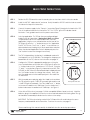
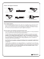
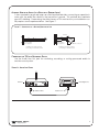
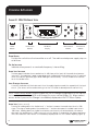
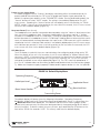
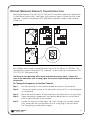
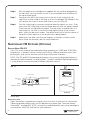
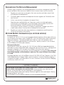
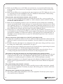
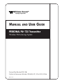
®
Williams
Sound
Helping People Hear
MANUAL
AND
USER GUIDE
PERSONAL PA® T35 Transmitter
Wireless FM Listening System
Transmitter Model PPA T35
Optional Receiver Models PPA R30, R7, R7-4, R19, R19-6
MAN 110 D
MANUAL
AND
USER GUIDE
Contents
Page
SYSTEM OVERVIEW
4
QUICK SETUP INSTRUCTIONS
5
DETAILED INSTALLATION INSTRUCTIONS
6
SELECT A LOCATION
INSTALLING THE ANTENNA
6
6
WIRING
7
AND
CONNECTIONS
REAR PANEL
CONNECTING THE POWER SUPPLY
AUDIO SOURCE CONNECTIONS
CHOOSING AN AUDIO SOURCE FOR THE HEARING IMPAIRED
AVOIDING GROUND LOOPS
CONNECTING TO A RECORDING DEVICE
CONTROLS
AND
FEATURES
7
7
7
8
9
9
10
FRONT PANEL CONTROLS
LCD SCREEN MENUS
APPLICATION PRESETS
BANDWIDTH
FREQUENCY
AUDIO SOURCE
HIGH PASS FILTER
LOW PASS FILTER
COMPRESSOR SLOPE
COMPRESSOR GAIN
RF OUTPUT
10
12
13
14
14
15
15
16
16
17
18
RECEIVER INSTRUCTIONS
19
WIDEBAND OPTIONS
FREQUENCY CHANGE INSTRUCTIONS
NARROWBAND OPTIONS
RECEIVER MANAGEMENT
BATTERY INFORMATION
19
21
22
24
24
TROUBLE-SHOOTING GUIDE
25
WARRANTY
27
SYSTEM SPECIFICATIONS
28
Williams
Sound ®
Helping People Hear
3
SYSTEM OVERVIEW
The PPA T35 is an FM Wide-band / Narrow-Band transmitter which operates in the 72-76 MHz
frequency bandwidth. It is designed to be used with battery powered FM receivers:
Compatible Williams Sound receivers include the R30, R7, R7-4 (Wide-Band), and the R19 and
R19-6 (Narrow-band). Please contact Williams Sound Corp. for more information on available
receivers: 800-843-3544. Or, visit us on the web: www.williamssound.com.
Developed for hearing assistance in places of public access, the PPA T35 is designed for
those who need help overcoming background noise, reverberation, or distance from the
sound source. It includes a complete audio processor optimized for the needs of hearing
impaired persons and is easily integrated with your existing sound system. The PPA T35 can
also be used with a microphone as a stand-alone system.
Your PPA T35 transmitter operates much like an FM radio station. The transmitter picks up the
live audio directly from a microphone or sound system. Those sounds are then broadcasted
over an FM radio signal. FM receivers are worn by the listener. The broadcast can be picked
up from up to 500 feet away*. This allows the listener to sit anywhere in the audience and listen to the broadcast as loud as needed without disturbing anyone else.
Please read through this manual carefully. It includes important setup procedures and guidelines for proper operation. If at any time you are having problems with this product, please
contact Williams Sound toll free for assistance: 800-843-3544.
NOTE: FCC regulations, section 15.21, requires the user to comply with the rules of transmitter
operation. Any changes or modifications made by the user not expressly approved for compliance may result in the loss of all privelages and authority to operate the equipment.
FIGURE 1: OVERALL SYSTEM DIAGRAM
Loudspeaker
Willia
ms So
und
Line-Level
Output
Willia
ms So
und
-3
Audio
Level
-6
–
^
-9
On Air
Power
Volume
-12
-15
-18
Sound System
Amplifier
Source
Digital Frequency Synthesized
+
-
0
^
Input
Overload
+
+3
-
+6
+
+9
PPA T35
Set
Phones
PPA T35 Transmitter
FM Receivers
Microphone
*Range may be affected by metal structures. 500+ feet is the maximum operating range of the T35
4
Williams
Sound ®
Helping People Hear
QUICK SETUP INSTRUCTIONS
STEP 1:
Position the PPA T35 transmitter near the sound system or mixer from which it will receive audio.
STEP 2:
Install the ANT 021 “rubber duckie” antenna. Gently thread the ANT 021 onto the stud recessed in
the hole on the top of the transmitter.
STEP 3:
Connect the power supply to the “Power In” connector (Figure 5) located in the back of the T35.
Press in the power button on the front of the T35. The “On Air” green LED indicator should
illuminate. If not, go back and check the power connections.
STEP 4:
Select an application. The T35 has three pre-configured Application Presets to choose from: Hearing Assist, Music and Voice.
The performance of the T35 is optimized for each selected
application. Using the menu
^ control buttons on the front of the
T35 (Figure 2), press the “ “ button to access the “Application
Presets” LCD screen. Press the “+” and “-” menu buttons to
alternate between Hearing Assist, Music and Voice selection.
When the desired Application Preset is displayed, press the
“Set” button to save the change into memory.
^
Configure the T35 for the appropriate audio source. Using the
menu
^ control buttons on the front of the T35 (Figure 2), press the
“ “ button to access the “Audio Source” LCD screen. Using the
“+” and “-” menu buttons (Figure 2), choose between MIC, SIMPLEX-MIC, or LINE. When the desired audio input is displayed, press
the “Set” button to save the change into memory. Lastly, connect the audio source to the audio input jack in the rear of the
T35 transmitter.
-
STEP 6:
The T35 is shipped from the factory in wideband mode with
the frequency set to 72.900 MHz. To change the frequency or
bandwidth on the T35, refer to the instructions on page 14.
^
+
STEP 5:
FIG. 2: LCD Menu Controls
Set
Front panel of the T35
FIG. 3: Audio Input Controls
+9
+6
Input
Overload
+
+3
0
-3
Audio
Level
-6
–
-9
-12
-15
-18
STEP 7:
STEP 8:
With the audio source playing, adjust the Audio Level control on
the T35 so that the green “0 dB” LED generally lights and the red
“+9 dB” LED lights occasionally: Press the Audio Level “+” button
to increase the audio level in .5dB steps. Press the Audio Level “-”
button to decrease the audio level in .5dB steps. See Figure 3.
Front panel of the T35
Listen with an FM receiver (see pages 19-23 for compatible Williams Sound receivers). Install the
batteries, plug in the earphone, turn on the receiver and walk around the listening area. The signal should be clear and quite loud when the volume is turned up.
IMPORTANT: The FM receiver being used with the T35 transmitter will need to be on the same
frequency and bandwidth as the transmitter. To retune the receiver, see page 21.
Please read through this manual carefully for detailed instructions and setup procedures.
Williams
Sound ®
Helping People Hear
5
SETTING UP
þ
THE
T35 - DETAILED INSTRUCTIONS
SELECT A LOCATION
The transmitter is usually located near the sound system amplifier or mixer for easy access to
an audio output signal. Position the transmitter on a level surface. It should be free from metallic objects that might interfere with the antenna signal.
For permanent installation, the PPA T35 transmitter can be rack mounted. Use the Williams
Sound RPK 005 or RPK 006 rack mount kits. Make sure there is good electrical contact
between the transmitter chassis and the rack cabinet.
þ
INSTALL
THE
ANT 021 ANTENNA
NOTE: If the T35 is going to be rack mounted, you will not be able to install the ANT
021 “Rubber Duckie.” For rack mounting, consider installing a remote antenna (see
following section).
The PPA T35 is shipped with a flexible antenna (ANT 021). The ANT 021 threads onto
a stud recessed in a hole on the top the transmitter. Screw the antenna clockwise
until the connection is secure (Figure 4). Do not use excessive force to tighten the
antenna. For operating the T35 in remote locations, a coaxial antenna (ANT 005) or
Wall Mount Dipole antenna (ANT 024) can be installed. The external antenna jack is
located at the rear of the T35 transmitter (Figure 4). The external antenna impedance is 75 ohms.
FIG. 4:
INSTALLING
THE
ANTENNA
Included:
ANT 021 "Rubber Duckie" Antenna
(T35 REAR VIEW)
Optional:
Coaxial Antenna (ANT 005) or
Wall Mount Dipole (ANT 024)
REMOTE ANTENNA TIPS:
Position the ANT 005 or ANT 024 antenna so the elements are vertical. The last 80 inches of the ANT 005 contain the elements. DO NOT install the antenna elements horizontally. The antenna should be placed as close to the listening area as possible (10
to 15 feet above the floor). DO NOT install the antenna directly above the listening
area. There is a null in the coverage area off the ends of the antennna. DO NOT install
the antenna around any significant amount of metal material; this may deflect and
absorb the radio signal.
The ANT 005 and ANT 024 cables are classified as Class II wiring and may be installed in
conduit with other Class II wiring. The antenna SHOULD NOT be installed with Class I
(power) wiring. DO NOT connect the coaxial cable to the building or electrical ground
in any way.
6
Williams
Sound ®
Helping People Hear
WIRING
AND
CONNECTIONS
FIG. 5: REAR VIEW
OF
T35
POWER SUPPLY CONNECTION FOR U.S. APPLICATION
þ
Connect the TFP 016 power supply to the “Power In”
jack located on the rear of the T35 transmitter.
NOTE: The power on the T35 will not be activated until the power
button on the front of the T35 is pressed into the “on” position.
TFP 016
Power
Supply Plug
AUDIO SOURCE CONNECTIONS
The T35 transmitter will accept the following audio sources:
1)
2)
3)
4)
5)
Balanced Microphone on a 3-pin (XLR) connector without simplex power.
Balanced Microphone with 12 volt simplex power (DIN 45596) on a 3-pin (XLR) connector.
Balanced/Unbalanced microphone without power on 1/4 inch jack
Balanced/Unbalanced Line on a 3-pin (XLR) connector.
Balanced/Unbalanced Line on 1/4 inch jack.
NOTE: The T35 is not designed to accept 70 volt speaker wire. The sound source should
come directly from the system mixer or amplifier as an unprocessed signal.
IMPORTANT: When a suitable audio source has been selected, you MUST configure the audio
source controls on the front panel of the T35. There are three possible selections to choose
from: MIC, SIMPLEX-MIC and LINE. SEE PAGE 15 FOR AUDIO SOURCE CONTROLS. After the
audio source selection has been made, plug in the appropriate audio source into the “Audio
Input” jack in the rear of the T35.
Williams
Sound ®
Helping People Hear
7
FIGURE 6: AUDIO SOURCE CONNECTORS
In Phase
In Phase
From Microphone
1
2
3
3 Pin Connector
1
In Phase
2
3
3 Pin Connector
Low Impedance Microphone
Balanced Line Using 3–Pin Connector
Balanced Line Using 1/4' Connector
4.7 K
1
3 Pin Connector
Source A
2
3
Unbalanced Line Using
3–Pin Connector
Source B
Unbalanced Line Using 1/4" Connector
4.7 K
Connecting to a Multi-Channel or
Stereo Source
MULTI–CHANNEL SOURCES
By constructing a simple resistive mixer, stereo (or 3 channel) sources can be connected to the T35. Additional channels can be accommodated by adding a resistor for
each source. Necessary resistors can be obtained from Williams Sound (Part Number
RFC 472) or from any local electronics parts supplier. See Figure 6.
SELECTING AN AUDIO SOURCE APPROPRIATE FOR HEARING IMPAIRED LISTENERS
If the T35 is going to be used specifically for the accommodation of hearing impaired listeners, we recommend following these general guidelines:
The PPA T35 transmits audio with excellent fidelity. Therefore, the audio source signal
should be of the highest audio quality and not subject to a compressor, limiter, reverberation, or other signal processing equipment. The T35 has an effective audio processor. If compression is desired in the audio, refer to pages 16-17 for features and controls.
Excessive compression is not helpful to the hearing impaired and can contribute to
excessive noise in the receiver outputs.
The T35 audio source signal is usually connected to a mixer’s “line output” signal which is
behind the mixer’s parametric equalizers but ahead of any equalization used for house
loudspeakers.
If audio delay is available for use in large auditoriums, it’s usually best to use it. Because
radio signals travel faster than sound, delaying the transmitted audio so that an average
listener (in the middle of the listening area) hears the transmitted audio a few milliseconds after audio from the main sound reinforcement system speaker is helpful. This will
also help audience members who lip read.
8
Williams
Sound ®
Helping People Hear
AVOIDING HUM IN THE AUDIO (AS A RESULT OF A GROUND LOOP)
A hum created by a ground loop can often be eliminated by connecting a capacitor in
series with the audio line shield to the transmitter’s ground. This method also maintains
good RF shielding. Determining the effectiveness of this method for your installation usually requires some experimentation. See Figure 7.
FIGURE 7: CONNECTING
TO A
BALANCE/UNBALANCED LINE
In Phase
1
2
3
.01 uF Ceramic
Disc Capacitor
.01 uF Ceramic
Disc Capacitor
Breaking A Ground Loop when
Connecting to a Unbalanced Line
3–Pin Connector
Breaking A Ground Loop when
Connecting to a Balanced Line
CONNECTING THE T35 TO A RECORDING DEVICE
Use the Audio Line Out jack for monitoring, recording, or routing processed audio to
another sound system.
FIGURE 8: AUDIO LINE OUTPUT
PPA T35
Recording Device
Audio Line Out
Williams
Sound ®
Helping People Hear
Audio Line In
9
CONTROLS & FEATURES
FIGURE 9: PPA T35 FRONT VIEW
Input
Overload
^
Digital Frequency Synthesized
Audio
Level
–
^
-9
Power
Volume
-
-3
-6
-
0
On Air
Source
+
+3
+
+6
+
+9
-12
-15
Set
PPA T35
-18
Power
Button
Direct Access
Buttons
LCD Menu
Display
Menu Control
Buttons
Phones
Direct Access
Buttons
POWER BUTTON
Push-button switch turns the transmitter on or off. The wall mounted power supply stays on
at all times.
ON AIR INDICATOR
Indicates when power is on and radio frequency is transmitting.
AUDIO LEVEL INDICATOR
The bar graph indicator shows audio level in 3dB steps at the input of the audio level processing circuit. The indicator is peak responding and is calibrated so that optimum level is reached
when the 0dB LED generally lights and +9dB lights occassionally. Use the Audio Level controls
to set the audio levels.
INPUT OVERLOAD INDICATOR
A red LED indicator will illuminate each time the audio signal exceeds the capacity of the input
circuit. (The source of the audio coming in to the T35 needs to be adjusted to correct this.)
NOTE: Direct Access Buttons (Figure 9) allow the user to change configurations on the transmitter immediately without having to scroll through the menu controls (Page 12). When a direct
access button is pressed, the change is immediately displayed on the LCD Menu Display.
AUDIO LEVEL (DIRECT
ACCESS)
Pressing or holding down the Audio Level “+” button increases the audio input level in .5dB
steps. Pressing or holding down the audio level “-” button decreases the audio input level in
.5dB steps. Holding down an Audio Level button continuously will automatically increase or
decrease the audio input in .5dB increments until the button is released or the upper and lower
limits are reached. Each action is immediately displayed on the LCD default display (Figure 9).
10
Williams
Sound ®
Helping People Hear
PHONES JACK AND SOURCE BUTTON
A headset plugged into the “Phones” jack allows monitoring either the audio output as it is
processed and transmitted by the T35 or the T35 audio input before it gets processed. By
default, the phone jack audio is set for “TRANSMITTED” audio. Pressing and holding down the
“Source” button will select “INPUT” audio. The setting is immediately displayed on the LCD
menu screen. Releasing the “Source” button will immediately return the selection to “TRANSMITTED” audio. If there is no further action by the user, after five seconds, the LCD menu screen
will return to the default display (Figure 10).
HEADPHONE VOLUME (DIRECT ACCESS)
The headphone level can be increased or decreased by using the “Volume” direct access buttons next to the headphone jack. Pressing or holding down the volume control “+” button
increases the headphone level in +0.5dB steps. Pressing or holding down the volume control “-”
button decreases the headphones level in -0.5dB steps. Holding down a Volume button continuously will automatically increase/decrease the input level in .5dB increments until the button is
released or the limit is reached. Each action is immediately displayed on the LCD menu screen
as the buttons are pressed. If there is no further action by the user, after five seconds, the LCD
menu screen will return to the default display (Figure 10).
LCD MENU DISPLAY
The LCD display is used with the menu control buttons for configuring and setting up the T35.
When the power of the unit is first turned on, the LCD screen displays a “Williams Sound” startup screen. (NOTE: If the transmitter is not fully functional, the transmitter will stay on the start-up
screen and the transmitter will not transmit.) After seven seconds, the “On Air” LED will illuminate and the default screen will be displayed (Figure 10). The T35 is now fully operational. If
the “On Air” indicator does not illuminate, go back and double-check the connections (page
7). Make sure the power supply is properly installed, and the power button is in the “on” position.
FIGURE 10: Default Display Menu
Operating Frequency
Audio Input Level
Application Preset
Menu Lock Icon
Menu Screen Number
Transmitting Power
The default display will always show the following information: Operating Frequency,
Bandwidth, Audio Input Level, Transmitting Power and Application Preset. In some cases the
Menu Lock Icon will be displayed. This indicates that the menu screens (page 12) are
locked, which prevents any functions from being accidently changed (except for the direct
access functions). To lock or unlock the menu screens, press and hold the SET button on the
front of the T35 for five seconds. NOTE: This will only work from the default display.
Williams
Sound ®
Helping People Hear
11
LCD SCREEN MENUS (QUICK REFERENCE)
The first screen (M0) gives important overall system settings. The following nine menu screens (M1M9) are used to configure and
^ setup the T35. To make a screen selection, navigate to the desired
LCD menu by pressing the “ “ (down) button on the front of the T35. Press the “Set” button to save
the change into memory. Any changes not “set” will be lost. After 30 seconds of inactivity, the LCD
will return to the default display.
LCD MENU
Input
Overload
0
^
Digital Frequency Synthesized
-3
Audio
Level
-6
–
-9
^
On Air
Power
-12
Volume
Phones
-15
-18
Source
+
+3
-
+6
+
+9
LED Menu Controls
-
AN
+
FIGURE 11: SELECTING
PPA T35
Set
Default
Application Presets
Bandwidth
Frequency
Audio Source
High Pass Filter
Low Pass Filter
Compressor Slope
Compressor Gain
RF Output
12
Williams
Sound ®
Helping People Hear
LCD SCREEN MENUS (DETAILED)
APPLICATION PRESETS (M1)
The Application Presets screen allows the user to quickly and easily configure the T35 for common
applications. In some cases, the Application Presets will be the only setup needed for properly configuring the T35 transmitter.
There are three Application Presets to choose from: Hearing Assist, Music and Voice. When one of
these selections is “set,” the performance of the T35 is immediately optimized for the needs of that
application (an adjustment is automatically made to the Low/High Pass Filter, and Compressor Slope
controls). Refer to the chart below for a comparison of the Application Preset configurations.
By default, the T35 is shipped in the Music mode. For music, concerts, and other applications where
the highest audio quality is desirable, Music is the recommended mode of operation. For hearing
assistance applications, or applications where the message is critical for listening, Hearing Assist is
the recommended mode of operation. For speaking and other voice applications, Voice is the preferred mode of operation.
To select an Application Preset:
FIGURE 12:
LCD Menu Controls
^
1)
Press the “ “ menu button (Figure 12) to access the LCD
“Application Presets” screen (M1).
2)
Press the “+” or “-” menu buttons to select between
Hearing Assist, Music and Voice.
3)
When the desired Application Preset is displayed, press the “Set” button to save the change into memory.
^
+
^
Set
Front panel of the T35
No additional action is necessary. After 30 seconds of inactivity, the LCD
screen will return to the default screen, where the selected Application
Preset will be displayed. NOTE: After an Application Preset has been selected, any of the configurations can manually be changed if necessary.
Application Preset Configuration Table
RF Output = Full Power, Compressor Gain = Normal
Wide Band
Parameters:
Low Pass Filter
High Pass Filter
Compressor Slope
Narrow Band
Hearing Assist
Music
Voice
Hearing Assist
Music
Voice
8.0 kHz
500 Hz
2.0: 1
16 kHz
22 Hz
1.0:1
6.3 kHz
125 Hz
1.0:1
6.3 kHz
500 Hz
2.0:1
6.3 kHz
22 Hz
1.0:1
6.3 kHz
125 Hz
1.5:1
The Application Presets are designed to take the guess work out of common setup procedures.
There will be times when manual adjustments will need to be made (i.e. to select a different operating frequency, bandwidth, to adjust the compression ratio, etc.). For these requirements, please
read through the manual and follow the corresponding menu control instructions. If you are unsure
of how these changes will impact the performance of the T35 transmitter, or how it will affect your
hearing assistance application, please contact Williams Sound for assistance at 800-843-3544.
Williams
Sound ®
Helping People Hear
13
BANDWIDTH (M2)
The default LCD menu screen (as shown on page 11, Figure 10) will always display the user selected
bandwidth as “Wideband” or “Narrowband.” The T35 is shipped from the factory in Wideband
mode. First determine the bandwidth of the associated receiver, then set the T35 to that bandwidth:
^
1) Press the “ “ menu button (Figure 12) to access the LCD “Bandwidth” (M2) screen.
2) Press the “+” or “-” menu buttons to select between Narrowband and Wideband.
3) When the desired bandwidth is displayed, press the “Set” button to save the change into memory.
No additional action is necessary. After 30 seconds of inactivity, the LCD screen will return to the
default screen, where the selected bandwidth will be displayed.
FREQUENCY (M3)
First determine the bandwidth and frequency of the associated receiver, then set the T35 to that
bandwidth (see above) and frequency:
Available Frequencies:
1.
If the wideband operation is selected, 10 wideband frequencies and 7 non-standard wideband
frequencies are available. Standard Frequencies:
72.100 (CH A), 72.300 (CH B), 72.500 (CH C), 72.700 (CH D), 72.900 (CH E), 74.700 (CH I),
75.300 (CH J), 75.500 (CH F), 75.700 (CH G) and 75.900 MHz (CH H).
Non-standard Frequencies:
72.2 (CH K), 72.4 (CH N), 72.6 (CH 0), 72.8 (CH P), 75.4 (CH R), 75.6 (CH S), 75.8 (CH T).
2.
If the narrowband operation is selected, seventy-seven narrowband frequencies are available:
72.025, 72.050, 72.075, 72.100, 72.125, 72.150, 72.175, 72.200, 72.225, 72.250, 72.275, 72.300,
72.325, 72.350, 72.375, 72.400, 72.425, 72.450, 72.475, 72.500, 72.525, 72.550, 72.575, 72.600,
72.625, 72.650, 72.675, 72.700, 72.725, 72.750, 72.775, 72.800, 72.825, 72.850, 72.875, 72.900,
72.925, 72.950, 72.975, 74.625, 74.650, 74.675, 74.700, 74.725, 74.750, 74.775, 75.225, 75.250,
75.275, 75.300, 75.325, 75.350, 75.375, 75.400, 75.425, 75.450, 75.475, 75.500, 75.525, 75.550,
75.575, 75.600, 75.625, 75.650, 75.675, 75.700, 75.725, 75.750, 75.775, 75.800, 75.825, 75.850,
75.875, 75.900, 75.925, 75.950, and 75.975 MHz.
The T35 is shipped from the factory with the frequency pre-set to 72.900 MHz. To change the frequency:
^
1) Press the “ “ menu button to select the LCD “Frequency” (M3) screen.
2) To increase the frequency, press the “+” menu button.
To decrease the frequency, press the “-” menu button.
Holding down the “+” or “-” menu buttons will change the frequency automatically until the
highest or lowest available frequency has been met.
3) When the desired frequency is displayed, press the “Set” button to save the change into memory.
No additional action is necessary. A new adjustment may now be made, or after 30 seconds of
inactivity, the LCD screen will return to the default screen, where the selected frequency will be
displayed.
NOTE: The T35 will not broadcast on the newly selected frequency until the “set” button has been pressed.
REMINDER: If the lock icon
is displayed on the default display, the menu screens are locked, and
you will not be able to make changes. To unlock the menu screens, refer to the instructions on page 11.
14
Williams
Sound ®
Helping People Hear
AUDIO SOURCE (M4)
The Audio Source control menu is used to configure the T35 for a proper audio source connection.
The transmitter will accept the following audio sources:
1)
2)
3)
4)
5)
Balanced Microphone on a 3-pin (XLR) connector without simplex power.
Balanced Microphone with 12 volt simplex power (DIN 45596) on a 3-pin (XLR) connector.
Balanced/Unbalanced microphone without power on 1/4 inch jack
Balanced/Unbalanced Line on a 3-pin (XLR) connector.
Balanced/Unbalanced Line on 1/4 inch jack.
The Audio Source menu has three possible selections to choose from: MIC, SIMPLEX-MIC, or LINE.
To select the audio input:
^
1) Press the “ “ menu button (Figure 12) to access the LCD “Audio Source” (M4) screen.
2) Press the “+” or “-” menu buttons to select between MIC, SIMPLEX-MIC, or LINE.
3) When the desired audio input is displayed, press the “Set” button to save the change into
memory.
No additional action is necessary. After 30 seconds of inactivity, the LCD screen will return to the
default display.
HIGH PASS FILTER (M5)
The high pass filter will help to remove low frequency “noise” from the transmitted audio signal. This
is typically used when there is room noise, a line hum, or breath accents picked up from an improperly installed microphone.
To select a High Pass Filter cutoff frequency:
1) Press the down “
^
“ menu button (Figure 12) to select the LCD “High Pass Filter” (M5) screen.
2) Press the “+” menu button to increase the cutoff frequency.
Each time the “+” button is pressed, the cutoff frequency will be raised by 1/2 octave. This
can be repeated until the cutoff frequency reaches the maximum 700 Hz.
Press the “-” menu button to decrease the cutoff frequency.
Each time the “-” button is pressed, the cutoff frequency will be lowered by 1/2 octave. This
can be repeated until the cutoff frequency reaches the minimum 22 Hz.
3) When the desired cutoff frequency is displayed, press the “Set” button to save the change
into memory.
No additional action is necessary. After 30 seconds of inactivity, the LCD screen will return to the
default display.
IMPORTANT: Listen to the transmitted audio through the headphone jack, especially when
deciding on an appropriate high pass filter. This is a good way to ensure the listening
audience is going to receive the highest audio quality.
Williams
Sound ®
Helping People Hear
15
LOW PASS FILTER (M6)
The low pass filter will help to remove high frequency “noise” from the transmitted audio signal. This
is typically used when there is a hiss is the audio line as a result of room noise, speech sibilants, or
other high frequency unpleasantries.
To select a Low Pass Filter cutoff frequency:
1) Press the down “
^
“ menu button (Figure 12) to select the LCD “Low Pass Filter” (M6) screen.
2) Press the “+” menu button to increase the cutoff frequency selection.
The cutoff frequency can be increased to a maximum of 16.0 kHz.
Press the “-” menu button to decrease the cutoff frequency selection.
The cutoff frequency can be decreased to a minimum of 3.2 kHz.
3) When the desired cutoff frequency is displayed, press the “Set” button to save the change
into memory.
No additional action is necessary. After 30 seconds of inactivity, the LCD screen will return to the
default display.
IMPORTANT: Listen to the transmitted audio through the headphone jack, especially when
deciding on an appropriate low pass filter. This is a good way to ensure the listening audience is going to receive the highest audio quality.
COMPRESSOR SLOPE (M7)
Compression is typically used for voice and hearing assistance applications. It reduces the
dynamic range: For a listener who has difficulty hearing the quiet sounds of an audio broadcast, compression will boost the quiet sounds to louder listening levels. For listening to music programs, concerts, etc., lower compression ratios or no compression is generally used.
The Compressor Slope has the following selectable compression ratios:
1.0:1, 1.1:1, 1.2:1, 1.3:1, 1.4:1, 1.5:1, 1.6:1, 1.8:1, 2.0:1, 2.2:1, 2.5:1, 3.0:1, 3.5:1, 4.0:1, 4.5:1, 5.0:1, 5.5:1, 6.0:1.
NOTE: The T35 is shipped from the factory at a 1.0:1 compression ratio (no compression).
To select a compression ratio:
^
1) Press the “ “ menu button (Figure 12) to select the LCD “Compressor Slope”
(M7) screen.
2) Press the “+” menu button to increase the steps of compression. The compression
ratio can increase to a maximum of 6:1, which produces generally loud output, even at
very low audio level signals.
Press the left “-” menu button to decrease the steps of compression. The compression
can be lowered to a minimum ratio of 1.0:1, which is no compression.
3) When the desired compression ratio is displayed, press the “Set” button to save the
change into memory. No additional action is necessary.
NOTE: The installer of the T35 needs to take care in using compression, because some hearing
impaired people cannot tolerate as loud of a sound as those with normal hearing.
16
Williams
Sound ®
Helping People Hear
FIGURE 13: AUDIO PERFORMANCE USING COMPRESSION
–18 –15 –12 –9 –6 –3
LEVEL INDICATOR
REFERENCE:
0 +3 +6 +9
1.0:1 RATIO
NORMAL or REDUCED GAIN
IO
RAT
3.5:1
-10 dB
)
ED
3.5:1 RATIO
REDUCED GAIN
C
DU
E
O
1
0:
(R
3.5:1 RATIO
NORMAL GAIN
COMPRESSION GAIN:
REDUCED ADJUSTMENT
RANGE
-20 dB
ES
SI
O
N
)
6.
TI
RA
-30 dB
1.
0:
1
R
AT
I
O
(N
O
C
O
M
PR
COMPRESSION GAIN:
NORMAL ADJUSTMENT
RANGE
-40 dB
-30 dB
-20 dB
-10 dB
0 dB
+10 dB
AUDIO OUTPUT LEVEL IN RECEIVER (RELATIVE)
0 dB
+20 dB
AUDIO INPUT LEVEL (RELATIVE)
COMPRESSOR GAIN (M8)
The T35 has two selectable modes of compression: Normal and Reduced. For applications
such as music and voice, where the highest audio quality is desirable, Reduced compression is
the recommended mode of operation. Reduced compression minimizes the amount of boost
and disturbances in the sound which compression can cause.
For hearing assistance or applications where the transmitting message is critical for listening, the T35
can be set to Normal Compression gain. Normal compression boosts the “soft” audio sounds for a
more understandable, consistent delivery. This may be appropriate for applications where the listening audience has moderate to severe hearing loss. Additional compression can be added (if desireable) by adjusting the Compressor Slope control. See page 16. Normal compression gain is generally not desirable for applications such as music, concerts, etc.
NOTE: The T35 is shipped from the factory in the Reduced mode.
To select Reduced or Normal Compression:
1) Press the “
^
“ menu button (Figure 12) to access the LCD “Compressor Gain” (M8) screen.
2) Press the “+” or “-” menu buttons to select between Reduced and Normal compressor gain.
3) When the desired compressor gain is displayed, press the “Set” button to save the
change into memory.
No additional action is necessary. After 30 seconds of inactivity, the LCD screen will return to the
default display.
NOTE: The installer must take care in using compression. Adding too much compression may contribute to excessive noise in the listener’s receivers.
IMPORTANT: Listen to the transmitted audio through the headphone jack, especially when
deciding on an appropriate compressor gain and slope. This is a good way to ensure the
listening audience is going to receive the highest audio quality.
Williams
Sound ®
Helping People Hear
17
RF OUTPUT (M9)
The T35 has three selectable transmitter power levels: FULL, MEDIUM, LOW POWER, or OFF AIR.
By default the T35 is set to “Full” power mode. For general listening applications, FULL power is
the preferred mode of operation. “Full power” provides the T35 with an operating range of up
to 500 ft. For special listening applications, it may be desirable to reduce the overall operating
range on the T35 if: 1) The audio transmission is to be contained to a “smaller” listening area;
2) The signal is too strong and it is overloading the receiver; or 3) Multiple T35 transmitters are
used in adjacent classrooms where the FM signals overlap each other. In these cases, the
power level on the T35 can be reduced to MEDIUM or LOW. The RF output may be set to OFF
AIR (no power) to help troubleshoot intefering or overlapping RF signals.
To select a power level:
1) Press the “
^
“ menu button (Figure 12) to access the “RF Output” (M9) screen.
2) Press the “+” and “-” menu button to select between: FULL POWER, MEDIUM POWER,
LOW POWER and OFF AIR.
3) When the desired power level is displayed, press the “Set” button to save the change
into memory.
No additional action is necessary. After 30 seconds of inactivity, the LCD screen will return to the
default display, where the selected power level will be displayed.
18
Williams
Sound ®
Helping People Hear
WIDEBAND FM RECEIVERS (OPTIONAL)
RECEIVER MODEL PPA R30
The R30 is a single-channel wideband receiver pre-tuned to 72.9 MHz (additional wideband frequencies are available from 72 MHz-76 MHz). It features a single volume control on/off switch, LED on indicator, and earphone jack. Instructions:
FIG. 14
Volume Control
On/Off Switch
Williams Sound
EAR
Volume
1
Earphone/Headphone
Jack
"On" Indicator
LED
R30 Top
R30 Front
BATTERY INSTALLATION
Open the battery compartment using a coin in the slot in the bottom of the receiver.
Press the AA batteries into place (see “Receiver Battery Information” on page 24),
observing proper battery polarity. Incorrect insertion of the batteries is difficult, and
may cause both mechanical and electrical damage to the receiver not covered by
the 5 year warranty. The receiver will not work with the batteries incorrectly installed.
CONNECTING EARPHONES
Plug an earphone into the jack near the thumb wheel volume control. Only monophonic earphones will operate properly. If stereo headphones are used, sound will be
heard only in one side. A suitable adapter (Radio Shack Part #274-368) can be used so
that stereo earphones operate on both sides. Williams Sound extensively evaluates the
earphones and headphones included with the PPA R30. We can only assure optimum
performance when Williams Sound earphones and headphones are used.
OPERATING
THE
RECEIVER
NOTE: If you’re using the PPA T35 transmitter, make sure the transmitter is on and receiving a good audio input. Also, make sure the T35 is operating in Wideband mode, and
transmitting on the same frequency as the receiver.
Turn the receiver on by rotating the volume control dial in the direction of the arrow on
top of the case. The “On” indicator will illuminate.
Turning the dial in the direction of the arrow will increase the volume. Turning the dial
against the arrow will decrease the volume. To avoid depleting the batteries, make
sure the receiver is turned off when not in use.
Williams
Sound ®
Helping People Hear
19
If you’re using the PPA T35 with a microphone—and not a complete sound system—
have someone speak into the microphone while you listen with the receiver and earphone. You should be able to hear their voice through the receiver.
Note: The earphone cord is the receiving antenna. Do not bunch up the cord or wrap
it around the receiver while in use.
ADDITIONAL WIDEBAND RECEIVER OPTIONS
MODEL PPA R7-4
The R7-4 is a four-channel wide-band receiver, pre-tuned to frequencies 72.1, 72.5,
72.9, and 75.7 MHz*. It features a channel select knob, volume control on/off switch,
and an earphone/charging jack. To operate, simply turn the select knob to the
desired frequency, and adjust the volume control to a comfortable listening level.
FIG. 15
On/Off
Indicator Light
Earphone/
Charging
Jack
EAR/CHG
Volume
1
Williams Sound
2 3
Volume Control
On/Off Switch
4
1
Channel
Channel Select
R7-4 Top
R7-4 Front
*Additional channels are available from 72 - 76 MHz.
20
Williams
Sound ®
Helping People Hear
RECEIVER (WIDEBAND) FREQUENCY CHANGE INSTRUCTIONS
Selecting a frequency for the R30, R31, R32 and R7-4 receivers requires an adjustment
to the internal tuning coil(s). See Figure 16 for receiver types to locate the coils to be
adjusted. A plastic tuning wrench (PLT 005) will be needed to adjust these receiver
tuning coils.
FIG. 16
1
1
1
2
2
IC01
R30
R- 31
R-32
TUNING COIL
1
R7- 4
2
3
4
Ferrite Tuning
"Slug"
Most Williams Sound single channel Receivers are set at the factory to 72.9 MHz. The
standard four-channel receivers (R7-4), channels 1-4, are usually set to frequencies 72.1,
72.5, 72.9, 75.7 MHz respectively.
The Receiver must be tuned with a weak and somewhat noisy signal. If tuned too
close to the transmitter, with a strong signal, the most accurate tuning of the receiver is
not possible.
To Change the Frequency to Another Channel:
Step 1:
Set the transmitter to the channel desired and remove the antenna.
Step 2:
Connect an audio source to the transmitter such as a CD or cassette player
or microphone.
Step 3:
Move the receiver about 25 feet away from the transmitter to set the tuning.
Step 4:
Open the battery compartment, then pull the battery door to the left like a
book to open the back of the receiver.
Step 5:
Locate the Tuning Coil (see Figure 16). Each tuning coil is a small, square,
shiny metal can with a screwdriver slot in a tuning slug in the top center.
The Tuning Slug is usually black or gray.
Williams
Sound ®
Helping People Hear
21
Step 6:
With the earphone or headphone supplied with the receiver plugged into
the Ear Jack, turn the volume control to a comfortable level, and listen for
the transmitted signal.
Step 7:
Gently put the tip of the tuning tool into the slot in the tuning slug. Be
careful not to push hard on the slug so as not to damage the threads in the
coil, and do not screw it down more than 3 turns into the coil.
Step 8:
Turn the tuning slug in a counter-clockwise direction about two turns. Then,
slowly turn the tuning slug in the clockwise direction until the signal is heard.
There may be two signal points heard. The one which is received first is a
false response. Be sure to continue tuning slightly further to the correct
point, which will be much louder. Tune back and forth to find the center of
the point of best response to the audio source being heard.
Step 9:
Mark down the date, and if a new frequency has been chosen, mark it
down inside the receiver case for future reference.
NARROWBAND FM RECEIVERS (OPTIONAL)
RECEIVER MODEL PPA R19
The R19 is a two-channel narrowband receiver operating on 72.900 and 75.700 MHz
frequencies. It features volume control on/off switch, channel selection switch, earphone jack, tone control selection switch and on/off power indicator.
NOTE: The R19 and R19-6 narrowband receivers use crystals to designate frequency
selection and are therefore not field tunable. To select a different operating frequency, the receiver must be returned to Williams Sound for service.
FIG. 17
Narrow Band
Tone Control
Earphone
Jack
EAR
Volume Channel
Lo Mid Hi
2
Tone
1
2
1
Off
Power
On/Off Indicator
Williams Sound
Volume Control
On/Off Switch
Max
R19 Top
Channel Switch
R19 Front
Instructions:
BATTERY INSTALLATION
Open the battery compartment using a coin in the slot in the bottom of the receiver.
Observing proper polarity, press the AA batteries into place (see “Receiver Battery
Information” on page 24). NOTE: Incorrectly installed batteries may cause damage to
your receiver, which will void the five year warranty.
22
Williams
Sound ®
Helping People Hear
CONNECTING EARPHONES
Plug an earphone into the “Ear” jack on the top of the R19 receiver. Only monophonic
earphones will operate properly. If stereo headphones are used, sound will be heard
only in one side. A suitable adapter (Radio Shack Part #274-368) can be used so that
stereo earphones operate on both sides.
OPERATING
THE
RECEIVER
NOTE: If you’re using the PPA T35 transmitter, make sure the transmitter is on and receiving a good audio source. Also, make sure the T35 is operating in Narrowband mode,
and transmitting on the same frequency as the receiver (72.900 MHz or 75.700 MHz).
Turn the receiver on by rotating the volume control knob clockwise. A green power
LED indicator will illuminate. If the power indicator does not illuminate, go back and
make sure the batteries are properly installed. If you are using rechargeable batteries,
you may need to charge the batteries overnight before operating the receiver.
Choose an operating frequency by sliding the channel selection switch to position 1
(72.900 MHz) or position 2 (75.700 MHz).
Turn the volume control knob clockwise until the audio is at a comfortable listening
level. Adjust the tone controls as needed by sliding the tone selection switch to low,
mid, or high. When you’re done using the receiver, be sure to turn off the unit. This will
help extend the life of the batteries.
ADDITIONAL NARROWBAND RECEIVER OPTIONS
MODEL PPA R19-6
The R19-6 is a six-channel narrowband receiver, pre-tuned to channels 72.1, 72.5, 72.9,
74.7, 75.3, and 75.7 MHz. It features a six-channel select knob, volume control on/off
switch, earphone jack, and power LED indicator. To operate, simply turn the volume
control knob clockwise to turn the unit on. The power LED indicator should illuminate.
Turn the channel switch to the desired frequency,and adjust the volume control knob
to a comfortable listening level.
FIG. 18
Narrow Band
Tone Controls
Earphone
Jack
Ear
Volume
Lo Mid Hi
2
1
Williams Sound
3 4
Volume Control
On/Off Switch
5
6
Tone
Power
On/Off Indicator
Off
Max
R19-6 Top
Channel
Channel Switch
R19-6 Front
Williams
Sound ®
Helping People Hear
23
SUGGESTIONS FOR RECEIVER MANAGEMENT
Different types of facilities use varying approaches to receiver management and earphone sanitation. Below are some options that customers have used successfully.
1.
Regular users purchase or are given their own receiver and take care of their
own batteries and earphones.
2.
The facility labels a receiver and earphone for each regular user. The facility maintains the units.
3.
Ushers issue receivers to people who request them.
Earphones are sanitized after use. Foam ear cushions can be replaced or
washed with a mild detergent, rinsed thoroughly and air-dried. The EAR 022
Surround Earphone can be sanitized with an alcohol pad.
The receivers can be stored in a multiple compartment storage case with a
credit card or driver’s license left as collateral for the receiver.
4.
Regular users purchase their own earphone or headphone and bring them
to use with receivers at the facility.
RECEIVER BATTERY INFORMATION (ALL
RECEIVER MODELS)
DISPOSABLE BATTERIES
In normal use, two AA 1.5 V non-rechargeable Alkaline batteries will last about 80 hours
(for 9V battery information, refer to page 29). If the sound becomes weak or distorted,
replace the battery. The indicator light may still be on, even with a battery that is
weak. Do not leave dead batteries in the receivers. Battery corrosion is not covered
by the Williams Sound five year warranty.
RECHARGEABLE BATTERIES
The R30 and R19 can also use two AA 1.5 V Ni-Cad or NiMH rechargeable batteries
(BAT 026). Two fully charged BAT 026’s will provide up to 50 hours of use. Damage from
improper charging is not covered by the Williams Sound five year warranty.
The batteries installed in the receiver may be recharged in the receiver only if they are
Nickel Metal Hydride or NiCad batteries, and only if the correct Williams Sound charger is used.
Recharge batteries only with a Williams Sound CHG 200A 3V Dual Charger or the CHG
1600 Multiple Battery Charger. Make sure the receiver is turned off during charging. A
complete recharge cycle takes about 14 hours. Receivers should not be left charging
continuously when not in use.
!! IMPORTANT WARNINGS !!
DO NOT ATTEMPT TO RECHARGE ZINC CARBON (“HEAVY DUTY”), ALKALINE, OR LITHIUM BATTERIES!
DO NOT ATTEMPT TO RECHARGE DISPOSABLE BATTERIES! These batteries may heat up and
explode, causing possible injury and damage to the equipment.
Avoid shorting the plus and minus battery terminals together with metal objects. Battery
damage and burns can result!
Use only Williams Sound supplied chargers and rechargeable batteries!
24
Williams
Sound ®
Helping People Hear
TROUBLE SHOOTING
THE T35 “ON AIR” INDICATOR
þ
IS NOT ON
Make sure the transformer (TFP 016) is plugged into the transmitter and any remote power
switch is on.
þ
Make sure the electrical outlet is on.
þ
Make sure the power button on the front of the T35 is pressed to the “on” position.
þ
Make sure the 24 VAC power supply is working.
þ
Make sure the RF output is not set to “OFF AIR.”
NO AUDIO
þ
þ
þ
þ
þ
þ
þ
þ
JACK
Check to see if there is an incorrect or defective connection from your audio source. See page 7
for detailed connection instructions.
OR
DISTORTION
IN THE
AUDIO
Check to see if there is noise in the audio source. To find out, disconnect the audio cable. If the
noise disappears your noise problem is in the source. Correct or repair your audio source.
Perhaps the Audio Source control is not set to match your audio source input device. See page 15
to properly configure the Audio Source control menu.
Check to see if the Audio Input level is set too high. If the “input overload” is illuminated, then
the audio level needs to be adjusted. See page 10.
Check for ground loops or noise on the input signal. See page 9 for more information. Call your
Authorized Williams Sound dealer or representative.
NOISE
þ
PHONES
Check to see if the Headphone Volume Level has been turned all the way down. If so, increase it.
NOISE
þ
HEARD IN
Check to see if there is a signal coming from your audio source. Check and correct your audio
source if necessary.
IN AUDIO
“GROWS”
WHEN PROGRAM IS SILENT
The Audio Level Control may be set too high. You’re probably also seeing the +6 level indicator
lighting all the time. To correct, adjust the Audio Level control on the front of the T35. See page 10.
It could be that the T35 Audio Processor is set for Normal Compression, which may be inappropriate
for the type of program being transmitted. Reset the Compressor Gain control to Reduced. See page 17.
It could be that the T35 Compressor Slope ratio is set too high, which may be inappropriate for
the type of program being transmitted. Reset the Compression Slope control to 1.0:1. See page 16.
RECEPTION (AT
RECEIVER) DIFFICULTIES
NOTE: Be sure to listen to the audio transmission on the T35 phone jack prior to checking the
receiver reception.
NO RECEPTION
þ
þ
Check to see if the antenna on the T35 has been disconnected. If so, attach the antenna correctly.
Check to see if the RF output power on the T35 is set to “OFF.” If so, reset the RF Output control to FULL, MEDIUM or LOW power. See page 18.
Williams
Sound ®
Helping People Hear
25
þ
þ
Make sure the FM receiver is ON. Make sure the batteries are properly installed (observing
proper polarity). If the batteries are rechargeable, it may be necessary to charge the batteries
overnight.
Make sure the FM receiver is operating on the same frequency as the T35. Make sure the receiver is operating on the same bandwidth as the T35: Wideband or Narrowband. Follow tuning
instruction for the receiver and adjust accordingly.
INSUFFICIENT
þ
þ
þ
Make sure the transmitting antenna is not in an unsuitable location. Perhaps the transmitting
antenna was installed inside a metal enclosure or is separated from the reception area by electrically conducting objects. (i.e., steel stud walls, heating ducts, substantial structural steel, or 2x2 or
2x4 ceiling grid.) In either case, reinstall the antenna according to installation instructions, locating it outside metal enclosures and away from electrically conducting objects.
Perhaps there is a strong interfering signal. If so, make sure the transmitter and antenna are correctly installed. Set the transmitter to FULL power output. If this does not solve the problem, try
operating the transmitter on a different frequency. If operating the T35 in wideband mode, try
switching to narrow band operation (see page 14). Narrowband operation is more resistant to
outside inteference.
USERS
þ
þ
þ
þ
þ
26
OR
5)
TO GET ENOUGH VOLUME
Some users may not be helped by this system. Severe hearing loss may require using the system
with a telecoil coupler (i.e., Neckloop) and personal hearing aid.
Check your batteries. For non-rechargeable (alkaline) batteries, they may need replaced. If you
are using rechargeable batteries, make sure the batteries are fully charged prior to use.
COMPLAIN OF TOO MUCH NOISE DURING SOFT AUDIO.
DYNAMIC
RANGE OF MUSIC REDUCED TOO GREATLY.
Check to see if the Audio Level control is set too high. This problem is more likely to occur in Normal
Compression mode, but can also occur in Reduced Compression mode. To reduce this noise, adjust
the Audio Level, carefully noting the Level Indicator. The +6 LED should light occasionally.
Perhaps the transmitter is set for Normal Compression when Reduced Compression would be more
suitable, given the program material. If so, set the Compressor Gain control to Reduced Compression.
See page 17.
IN OTHER EQUIPMENT WHEN TRANSMITTER IS ON OR OFF
This is not an RF problem. Instead, it is likely caused by incorrect audio connections, a ground
loop, or defective equipment. To remedy, use proper audio wiring practice to make connections
described on page 8.
BUZZ
þ
4
It could be that the audio input is not configured for the audio source being used. If not, correct
the setting of the Audio Source control menu. See page 15.
BUZZ
þ
MUST TURN RECEIVER VOLUME CONTROLS WAY UP (TO
Perhaps there is insufficient audio level. If so, the audio level indicator will read too low because the
audio level control is set incorrectly on the transmitter. Correct the Audio Level control setting. See
page 10.
USERS
þ
RANGE, GOOD RECEPTION NEAR TRANSMITTER, POOR AT A DISTANCE
Check to see if the transmitting antenna was installed incorrectly. If so, correct or replace the
antenna. The signal should be clearly audible at a 300 foot distance with the ANT 021 and a 500
foot distance with the ANT 005.
OR OTHER NOISE IN EQUIPMENT ONLY WHEN TRANSMITTER IS ON
This is likely an RF–induced disturbance in the other equipment. To remedy, try these steps in
order until the buzz is eliminated:
Williams
Sound ®
Helping People Hear
1.
2.
3.
4.
5.
6.
Make certain the transmitter chassis is connected to the equipment cabinet rails.
Buzz/hum in system may be experienced when the T35 chassis is insufficiently grounded.
In this case, install a ground wire to the T35 chassis and terminate to a known good
ground source.
Make sure antenna connections are secure.
Set the T35 Transmitter to MEDIUM power output on the RF Power menu choice.
Install transmitter at a distance from sensitive equipment.
Use a remote antenna (ANT 005 or ANT 024).
Make sensitive equipment more immune to RFI/EMI. The manufacturers of your audio
equipment may offer application notes for this purpose. Williams Sound offers a document giving suggestions for improving RF immunity in existing audio equipment
(Technical Bulletin: Buzz Or Hum In The Sound System, FRM 531).
WARRANTY
The Williams Sound T35 Transmitter is engineered and designed to provide you with many years of
reliable service. Williams Sound warrants it against defects in materials and workmanship for FIVE
(5) years EXCEPT FOR earphones, headphones, rechargeable batteries, chargers, cables, antennas,
carry cases, and all other accessory products. Accessory products carry a 90 day warranty.
If this product fails within the specified warranty period, Williams Sound will determine whether
to repair or replace the defective equipment. This warranty does not apply to physical damage,
abuse, mis-use, or products that have been modified.
If you experience difficulty with your system, call for Customer Assistance:
1-800-843-3544.
If it is necessary to return the system for service, a Williams Sound representative will give you a
Return Authorization Number (RA) and shipping instructions. Pack the system carefully and
send it to:
Williams Sound Corp.
10321 West 70th Street
Eden Prairie, MN 55344-3459 USA
Phone:
Fax:
TTY:
e-mail:
800-843-3544 / 952-943-2252
952-943-2174
952-943-9675
[email protected]
Your warranty becomes effective the date you purchase your system. Your returned warranty
card is our way of knowing when your warranty begins. You may also choose to register your
product online:
http://www.williamssound.com/registration.html
This information will help us serve you better in the future. Thank you.
Williams
Sound ®
Helping People Hear
27
SYSTEM SPECIFICATIONS
Personal PA T35 Transmitter
Dimensions, Weight:
Color:
Rack Mount:
Power:
FCC ID:
Temperature Range:
Operating Freqs:
Frequency Accuracy:
Deviation:
Pre-Emphasis:
RF Field Strength:
Note:
Nominal Range:
Audio Proc. Functions:
Frequency Response:
Signal to Noise Ratio:
Audio Level Control:
Audio Level Indicators:
Power On Indicator:
Phones Output:
Audio Input:
Line Output:
LCD Menu Controls:
(Push-button selection)
Input Levels (Bal or Unbal):
Microphone Simplex-Mic:
Line:
Simplex Mode:
RF “Off” Timer:
Common Mode Rejection:
Total Harmonic Distortion:
Warranty:
8.45" (21.5 cm) W x 8.18" (20.8 cm) D x 1.72" (4.4 cm) H, 3.1 lbs. (1.4 kg)
Black with white legends
One EIA rack space high, 1/2 space wide
1–2 units can be mounted in a single rack space with optional RPK 005 (single) or
RPK 006 (double) Rack Mount Kits
Wall mount Class II transformer (TFP 016)
Input: 120VAC, 60Hz, 17W
Output: 24VAC, 500mA with 3-pin Molex® plug
Approvals: UL, CSA listed
CNMT35
Operating: 0°C to 40°C (+32°F to +104°F)
Storage: -20°C to 70°C (-4°F to +158°F)
72.1–75.9 MHz , 10 wideband channels (selectable), 7 non-standard wideband
channels (selectable) OR
72.025 - 75.975 Mhz, 77 narrowband channels (selectable)
±.005% stability, 0-50˚ C
Wideband: ± 75 kHz maximum. Narrowband: ± 5kHz maximum
Wideband: 75 µsec, Narrowband: 300 µsec
Does not exceed 8 mV/m at 3 m
Maximum transmitter range is achieved using the ANT 005 coaxial antenna
300-500 ft. (90-150 m)
Reduced or Normal Compressor Gain
Compression Slope Control
High Pass and Low Pass Filter Frequency control
22 – 16000 Hz, +1, -3 dB (adjustable)
74dB (transmitted)
Push-button audio level controls, adjustable to 0 to -50dB
10 LED array that reads +9 to -18 at 3dB intervals
Green LED indicates power on
Mono signal, 1/4" TRS stereo jack, 67mW, maximum in 50 ohms (adjustable 0 to -40dB)
Combination 3-pin XLR, 1/4" TRS jack
RCA jack, -10dBV (.32VRMS) output, impedance 100 Ω
Applications Presets (Music, Voice, Hearing Assist)
Bandwidth, Frequency, Audio Input Source (Microphone, Line, Simplex), High Pass
Filter, Low Pass Filter, Compressor Slope, Compressor Gain, RF Output Power.
Nominal (1st Amber LED)
Maximum (Input Overload LED)
Absolute Maximum Ratings1
-60dBV (1mVRMS)
-20dBV (100mVRMS)
+20dBV (10.0VRMS)
-8dBV (400mVRMS)
+16dBV (6.3VRMS)
+20dBV (10.0VRMS)
12 volts simplex power (DIN 45596) on the 3-pin XLR connector
Turns off RF signal after 1 hour of no audio activity
Mic or Line > 57dB @ 1kHz
< 0.25% @ -10dBV audio line output, 1kHz
Five Years, Parts and Labor
90 days on cords, antenna, power supply and accessories
SPECIFICATIONS SUBJECT TO CHANGE WITHOUT NOTICE.
1Notes: Stresses above these ratings may cause permanant damage. Exposure for extended periods may degrade reliability.
28
Williams
Sound ®
Helping People Hear
Personal PA R30 Wideband Receiver
Dimensions:
Weight:
Color:
Battery Type:
3-5/8" L x 2-3/8" W x 7/8" H (92.1 mm x 60.3 mm x 22.2 mm)
4.6 oz (130 g) with batteries
Gray
Two (2) AA 1.5 V non-rechargeable Alkaline batteries (BAT 001), 14 mA nominal current drain, 80
hours approx. life (OR) Two (2) AA 1.5 V NiMH rechargeable batteries (BAT 026), 14 mA nominal
current drain, 50 hours per charge approx., recharges in 14–16 hours, uses CHG 1600 Charger or
CHG 200 Charger
FCC ID:
CNM R30
Industry Canada Cert.: 13601021234
Operating Freq.:
Pre-Tuned, Adjustable, 72 MHz - 76 MHz
Intermediate Freq.:
75 kHz
FM Deviation:
75 kHz
De-Emphasis:
75 µS
AFC Range:
± 120 kHz
Sensitivity:
4 µV at 12 dB Sinad
Input Overload:
20 mV
Frequency Response:
100 – 10 kHz, ± 3 dB
Signal-to-Noise Ratio:
65 dB at strong signal condition
Receive Antenna:
Integral with earphone/headphone cord
Audio Output:
35 mW, max. at 16 Ω
Output Connector:
3.5 mm mono phone jack
Earphone:
Earbud-type with foam cushion, 3.5 mm plug, 32 Ω
Warranty:
Five Years, Parts and Labor.
90 days on cords, earphones, headphones, batteries and other accessories
Notes:
The R30 Receiver can be field tuned to any of 10 wideband channels using the PLT 005 Tuning Tool.
Personal PA R7-4 Wideband Receiver
Dimensions:
Weight:
Color:
Battery Type:
Battery Drain:
Battery Life:
FCC ID:
Operating Freq.:
3-5/8" L x 2-3/8" W x 7/8" H (92.1 mm x 60.3 mm x 22.2 mm)
3.2 oz (90 g) with battery
Gray
9 Volt, Eveready 216 Carbon, Eveready 522 Alkaline, or BAT 003 Ni-Cad Rechargeable
14 mA, nominal
32 hours with Eveready 522, 6 hours/charge with BAT 003
CNM R7Y, CNM R74Y
4-Channel, Pre-Tuned, Selectable
CH A (72.1 MHz), CH C (72.5 MHz), CH E (72.9 MHz), CH G (75.7 MHz)
(OR)
CH B (72.3 MHz), CH D (72.7 MHz), CH F (75.5 MHz), CH H (75.9 MHz)
Intermediate Freq.:
75 kHz
FM Deviation:
75 kHz
De-Emphasis:
75 µS
AFC Range:
± 300 kHz
Sensitivity:
2 µV at 12 dB Sinad with squelch defeated
Input Overload:
20 mV
Squelch:
Squelches at 10 µV for minimum
50 dB S/N ratio
Frequency Response: 100–10 kHz, ± 3 dB
Signal-to-Noise Ratio: 65 dB at strong signal condition
Receive Antenna:
Integral with earphone/headphone cord
Audio Output:
250 mW, max. at 16 Ohms
Output Connector:
3.5 mm mini phone jack, also serves as a charging jack for rechargeable battery
Earphone:
Earbud-type with foam cushion, 3.5 mm plug, 32 Ω (Other styles available)
Channel Selector:
4–position, rotary switch
Warranty:
Five Years, Parts and Labor.
90 days on cords, earphones, headphones, batteries and other accessories
Williams
Sound ®
Helping People Hear
29
Personal PA Receiver Models R19 and R19-6
Model PPA R19:
2-Channel, Pre-Tuned, Selectable
CH 36 (72.9 MHz), CH 66 (75.7 MHz) standard
10 Channels Available (72.1-75.9 MHz)
Model PPA R19–6:
6-Channel, Pre-Tuned, Selectable
CH 4 (72.1 MHz), CH 20 (72.5 MHz),
CH 36 (72.9 MHz), CH 66 (75.7 MHz)
CH 43 (74.7 MHz), CH 50 (75.3 MHz)
3-5/8" L x 2-3/8" W x 7/8" H
(92.1 mm x 60.3 mm x 22.2 mm)
3.2 oz (90 g) with battery
Neptune Blue
(2) BAT 001 AA Alkaline
or (2) BAT 026 NiMH
20 mA, nominal
90–100 hrs with 2 AA Alkaline
45-50 hrs/charge with BAT 026
Crystal controlled. See factory for frequency changing instructions.
10.7 MHz, 455 kHz
CNMR19
Earbud-type with foam cushion, 3.5 mm plug, 32 Ω
3.5 mm mini phone jack
Narrow–band, 5 kHz
300 µS
0.7 µV at 12 dB Sinad
4 µV for minimum 40 dB S/N ratio
100 – 5 kHz, ± 3 dB (Tone: Lo)
Integral with earphone cord
50dB
125 mW, max. at 32 Ω (Tone: Lo; 3 VDC Bat.)
125 dB Max SSPL90 with EAR 013
Dimensions:
Weight:
Color:
Battery Type:
Battery Drain:
Battery Life:
Operating Freq:
Intermediate Freqs:
FCC ID:
Earphone:
Output Connector:
FM Deviation:
De-Emphasis:
Sensitivity:
Squelch Level:
Frequency Response:
Receiver Antenna:
Signal-to-Noise Ratio:
Audio Output:
Acoustic Output:
CONTROLS
Tone:
Volume & On/Off:
Channel Selector:
Warranty:
30
Switched Low-Cut
Lo: 20 Hz / Mid: 120 Hz / Hi: 700 Hz
Combination, integral
PPA R19: 2-position, slide switch
PPA R19-6: 6-position, rotary switch
Five Years, Parts and Labor.
90 days on cords, earphones, headphones, batteries and other accessories
Williams
Sound ®
Helping People Hear
®
Williams
Sound
Helping People Hear
MAN 110D
©2003 Williams Sound Corp.
w w w. w i l l i a m s s o u n d . c o m