1
F3 TREADMILL
ASSEMBLY &
USER MANUAL
CORPORATE HEADQUARTERS
5100 North River Road
Schiller Park, Illinois 60176 • U.S.A.
www.lifefitness.com
INTERNATIONAL OFFICES
LIFE FITNESS ASIA PACIFIC LTD
Room 2610, Miramar Tower
132 Nathan Road
Tsimshatsui, Kowloon
HONG KONG
LIFE FITNESS ATLANTIC BV
LIFE FITNESS BENELUX
Bijdorpplein 25 - 31
2992 LB Barendrecht
THE NETHERLANDS
LIFE FITNESS DO BRAZIL
Av. Dr. Dib Sauaia Neto 1478
Alphaville, Barueri, SP
06465-140
BRAZIL
LIFE FITNESS VERTRIEBS GMBH
Dückegasse 7-9/3/36
1220 Vienna
AUSTRIA
LIFE FITNESS IBERIA
Pol. Ind. Molí dels Frares. c/C, nº 12
08620 Sant Vicenç dels Horts (Barcelona)
SPAIN
LIFE FITNESS UK LTD
Queen Adelaide
Ely, Cambs CB7 4UB
UNITED KINGDOM
LIFE FITNESS EUROPE GMBH
Siemensstrasse 3
85716 Unterschleissheim
GERMANY
LIFE FITNESS JAPAN
Nippon Brunswick Bldg., #8F
5-27-7 Sendagaya
Shibuya-Ku, Tokyo
JAPAN 151-0051
LIFE FITNESS ITALIA S.R.L.
Via Vittorio Veneto, 57/A
39042 Bressanone (Bolzano)
ITALY
LIFE FITNESS LATIN
AMERICA and CARIBBEAN
5100 North River Road
Schiller Park, Illinois 60176
U.S.A.
8119901 Rev A-1
08/06
1
Before using this product, it is essential to read this
ENTIRE operation manual and ALL installation instructions.
This will help in setting up the equipment quickly
and in instructing others on how to use it correctly and safely.
FCC Warning - Possible Radio / Television Interference
NOTE: This equipment has been tested and found to comply with the limits for a Class B digital device, pursuant to
part 15 of the FCC rules. These limits are designed to provide reasonable protection against harmful interference in
a residential installation. This equipment generates, uses and can radiate radio frequency energy, and if not installed and
used in accordance with the operation manual, may cause harmful interference to radio communications. However, there
is no guarantee that the interference will not occur in a particular installation. If this equipment does cause harmful interference to radio or television reception, which can be determined by turning the equipment off and on, the user is
encouraged to try to correct the interference by one or more of the following measures:
Reorient or relocate the receiving antenna.
Increase the separation between the equipment and the receiver.
Connect the equipment into an outlet on a circuit different from that to which the receiver is connected.
Consult the dealer or an experienced radio/TV technician for help.
Class HB (Home): Domestic use. Not suitable for therapeutic purposes.
CAUTION: Any changes or modifications to this equipment could void the product warranty.
Any service, other than cleaning or user maintenance, must be performed by an authorized service representative.
There are no user-serviceable parts.
2
TABLE
1.
OF
CONTENTS
Important Safety Instructions . . . . . . . . . . . . . . . . . . . . . . . . . . . . . . . . . . . . . . . . . . . . . . . . . . . . . . . . . . . . . . . . .5
2.
Assembly . . . . . . . . . . . . . . . . . . . . . . . . . . . . . . . . . . . . . . . . . . . . . . . . . . . . . . . . . . . . . . . . . . . . . . . . . . . . . . .8
2.1
Unpacking . . . . . . . . . . . . . . . . . . . . . . . . . . . . . . . . . . . . . . . . . . . . . . . . . . . . . . . . . . . . . . . . . . . . . . . . . . . . . .8
2.2
Parts List . . . . . . . . . . . . . . . . . . . . . . . . . . . . . . . . . . . . . . . . . . . . . . . . . . . . . . . . . . . . . . . . . . . . . . . . . . . . . . .9
2.3
Installing Uprights and Handlebars . . . . . . . . . . . . . . . . . . . . . . . . . . . . . . . . . . . . . . . . . . . . . . . . . . . . . . . . . . . .10
2.4
Installing the Console . . . . . . . . . . . . . . . . . . . . . . . . . . . . . . . . . . . . . . . . . . . . . . . . . . . . . . . . . . . . . . . . . . . . .12
2.5
Attaching Power Cord . . . . . . . . . . . . . . . . . . . . . . . . . . . . . . . . . . . . . . . . . . . . . . . . . . . . . . . . . . . . . . . . . . . . .13
2.6
Calibration . . . . . . . . . . . . . . . . . . . . . . . . . . . . . . . . . . . . . . . . . . . . . . . . . . . . . . . . . . . . . . . . . . . . . . . . . . . . . .13
3.
Setup . . . . . . . . . . . . . . . . . . . . . . . . . . . . . . . . . . . . . . . . . . . . . . . . . . . . . . . . . . . . . . . . . . . . . . . . . . . . . . . . .14
Electrical Power Requirements // Grounding Instructions // How to Stabilize the Life Fitness Treadmill
Raising and Lowering Treads // Power Switch // Immobilizing the Treadmill // Centering the Belt
4.
Features . . . . . . . . . . . . . . . . . . . . . . . . . . . . . . . . . . . . . . . . . . . . . . . . . . . . . . . . . . . . . . . . . . . . . . . . . . . . . . .18
5.
Service and Technical Data . . . . . . . . . . . . . . . . . . . . . . . . . . . . . . . . . . . . . . . . . . . . . . . . . . . . . . . . . . . . . . . . .21
5.1
Troubleshooting . . . . . . . . . . . . . . . . . . . . . . . . . . . . . . . . . . . . . . . . . . . . . . . . . . . . . . . . . . . . . . . . . . . . . . . . . .21
5.2
Preventive Maintenance Tips . . . . . . . . . . . . . . . . . . . . . . . . . . . . . . . . . . . . . . . . . . . . . . . . . . . . . . . . . . . . . . . .24
5.3
How to Adjust and Tension the Striding Belt
Reading Rack // Accessory Trays // Activity Zone // Hand Pulse Sensor System
. . . . . . . . . . . . . . . . . . . . . . . . . . . . . . . . . . . . . . . . . . . . . . . . . . . .25
The Belt Tensioning Bolts // Tracking (Centering) an Existing or New Striding Belt //
Tensioning an Existing Striding Belt
5.4
How to Obtain Product Service . . . . . . . . . . . . . . . . . . . . . . . . . . . . . . . . . . . . . . . . . . . . . . . . . . . . . . . . . . . . . .27
6.
Specifications . . . . . . . . . . . . . . . . . . . . . . . . . . . . . . . . . . . . . . . . . . . . . . . . . . . . . . . . . . . . . . . . . . . . . . . . . . .28
7.
Warranty Information . . . . . . . . . . . . . . . . . . . . . . . . . . . . . . . . . . . . . . . . . . . . . . . . . . . . . . . . . . . . . . . . . . . . . .30
© 2006 Life Fitness, a division of Brunswick Corporation. All rights reserved. Life Fitness and FlexDeck are registered trademarks and Lifespring, Go System-Quick Start,
HeartSync, Heart Rate Hill, Heart Rate Interval, Extreme HR, EZ Incline, and 5K (and 10K) Sport Training are trademarks of Brunswick Corporation. Polar is a registered
trademark of Polar Electro, Inc. Any use of these trademarks, without the express written consent of Life Fitness or the corresponding companies is forbidden.
3
This Operation Manual describes the functions of the following product:
Life Fitness Treadmill Model:
F3
Thank you for purchasing a Life Fitness treadmill. Before using this product please read this user manual in its entirety
to ensure that you have the knowledge to safely and properly operate all of the features on your treadmill. We hope you
achieve the product experience on your treadmill that you expect, but if you do have any service issues please go to the
How to Obtain Product Service page in the How To section which will provide information on obtaining domestic and
international product service. See "Specifications" in this manual for product specific features.
Statement of Purpose: The Treadmill is an exercise machine that enables users to walk or run in place on a moving surface.
CAUTION:
Health-related injuries may result from incorrect or excessive use of exercise equipment. The manufacturer
STRONGLY recommends seeing a physician for a complete medical exam before undertaking an exercise
program, particularly if the user has a family history of high blood pressure or heart disease; or is over the age
of 45; or smokes, has high cholesterol, is obese, or has not exercised regularly in the past year. The
manufacturer also recommends consulting a fitness professional on the correct use of this product.
If, at any time while exercising, the user experiences faintness, dizziness, pain, or shortness of breath,
he or she must stop immediately.
4
1
IMPORTANT SAFETY INSTRUCTIONS
WARNING: READ ALL INSTRUCTIONS BEFORE USING THE TREADMILL. SAVE THESE INSTRUCTIONS.
DANGER: To reduce the risk of electrical shock, always unplug this Life Fitness product before cleaning or attempting any
maintenance activity.
WARNING: To reduce the risk of burns, fire, electric shock or injury, it is imperative to connect each product to a properly
grounded electrical outlet.
WARNING: This treadmill has immobilization or lock out software. Only activate software lockout when treadmill is not in use.
Refer to this user manual for instructions on immobilizing the treadmill. Keep instructions out of reach of children.
WARNING: Do not move the treadmill by lifting the console. Do not use the console as a handlebar during a workout.
•
Risk of injury to persons – To avoid injury stand on the side rails before starting the treadmill.
•
To disconnect, turn power OFF at the ON/OFF switch, then remove plug from electrical outlet.
•
Never operate a Life Fitness product if it has a damaged power cord or electrical plug, of if it has been dropped, damaged,
or even partially immersed in water. Contact Life Fitness Customer Service.
•
Position this product so the power cord plug is accessible to the user.
•
Keep the power cord away from heated surfaces. Do not pull the equipment by the power cord or use the cord as a handle.
Do not run the power cord on the floor, under or along the side of the treadmill.
•
If the electrical supply cord is damaged it must be replaced by the manufacturer, an authorized service agent, or a similarly
qualified person to avoid a hazard.
•
Do not use this product in areas where aerosol spray products are being used or where oxygen is being administered. Such
substances create the danger of combustion and explosion.
•
Always follow the console instructions for proper operation.
•
Close supervision is necessary when used by, or near, children or disabled persons.
5
6
•
Do not use this product outdoors, near swimming pools or in areas of high humidity.
•
Never operate a Life Fitness product with the air openings blocked. Keep air openings free of lint, hair or any obstructing
material.
•
Never insert objects into any openings in this product. If an object should drop inside, turn off the power, unplug the power
cord from the outlet and carefully retrieve it. If the item cannot be reached, contact Life Fitness Customer Service.
•
Never place liquids of any type directly on the unit, except in a bottle holder or accessory tray. Lidded containers are recommended.
•
When using the treadmill, wear shoes with rubber or high traction soles. Do not use shoes with heels, leather soles, cleats or
spikes. Make sure no stones are embedded in the soles. Do not use this product in bare feet. Keep all loose clothing,
shoelaces and towels away from moving parts.
•
Do not reach into or underneath the unit, or tip it on its side during operation.
•
Keep an open area of six feet (2 meters) by three feet (1 meter) behind the treadmill clear of any obstructions, including
walls, furniture and other equipment.
•
Use the hand rails whenever additional stability is required. In case of emergency, such as tripping, the user should grab the
hand rails and place his/her feet on the side platforms. The hand rails may be held to enhance stability as needed, but are
not for continuous use.
•
Never walk or jog backwards on the treadmill.
•
Immobilize the treadmill so the motors will not run when the unit is not in use. To do this, press and hold both the down arrow
and the enter key on the console.
•
Activate software lockout when not in use. Refer to Console Owner’s Manual for lockout instructions. Store instructions ouf of
reach of children.
•
Use caution when folding and unfolding the treadmill. Do not let the treadmill lower to the floor unassisted. Guide the deck to
the floor by hand.
•
Use this appliance only for its intended use as described in this manual. Do not use attachments not recommended by the
manufacturer.
HAND PULSE HEART RATE SENSORS
The heart rate hand pulse sensors found on your Life Fitness F3 fitness product provide an approximate heart rate
value. The sensors are not medical devices and should not be used in any type of medical application. If you purchased the advanced console use the Polar heart rate chest strap that was included with your product for more accurate
readings.
To improve heart rate accuracy when using the hand pulse sensors follow the guidelines below.
•
Remove hands from heart rate sensors and wait for heart rate display to disappear. Grasp sensors again.
•
Make sure hands are fully contacting the sensors.
•
Dry hands periodically during use.
•
Limit movement. Life Fitness recommends the hand pulse sensors on treadmills be used when standing
on side rails.
•
Clean hand pulse sensors per recommended maintenance in user manual.
7
2
ASSEMBLY
For safety, and to save time and effort, read these setup instructions and the Operation Manual completely before
installing your Life Fitness Treadmill. Place the treadmill near where it will be used before beginning the unpacking
procedure.
2.1
UNPACKING
These unpacking instructions assume you have already done the following:
•
Removed the top of the shipping carton.
•
Removed the styrofoam packing material.
•
Removed these assembly instructions from the bridge assembly carton.
The best method for unpacking the rest of the treadmill proceeds as follows:
•
Remove the bridge assembly carton from the base unit.
•
Break down the sides of the inner shipping carton.
•
Remove the treadmill uprights from the shipping carton.
•
Assemble the treadmill. Once assembly is complete:
8
-
Fold the treadmill upward until it locks in its upright position.
-
Roll the treadmill off of the shipping carton and to the location where it will be used.
2.2
PARTS LIST
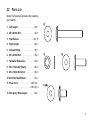
Identify the following components after unpacking
your treadmill:
1. Left Upright . . . . . . . . . . . . . . . . . . . Qty: 1
2. M8 x 60mm Bolt. . . . . . . . . . . . . . . . Qty: 6
3. Star Washers . . . . . . . . . . . . . . . . . Qty: 19
4. Right Upright . . . . . . . . . . . . . . . . . . Qty: 1
5. Console Bridge . . . . . . . . . . . . . . . . Qty: 1
6. M8 x 25mm Bolt. . . . . . . . . . . . . . . . Qty: 3
7. Handlebar Extensions . . . . . . . . . . . Qty: 2
8. M8 x 15mm Bolt (Black) . . . . . . . . . Qty: 4
9. M8 x 15mm Bolt (Zinc) . . . . . . . . . . Qty: 6
10. 6mm Hex Head Wrench . . . . . . . . . . Qty: 1
11. Power Cord. . . . . . . . . . . . . . . 120V Qty: 1
. . . . . . . . . . . . . . . . . . . . . . . . 230V Qty: 3
12. Emergency Stop Lanyard . . . . . . . . Qty: 1
9
2.3
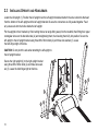
INSTALLING UPRIGHTS AND HANDLEBARS
Locate the left upright (1). Position the left upright near the left upright bracket and attach the wire connectors that lead
from the bottom of the left upright and the left upright bracket. Be sure the connectors are fully seated together. Feed
any excess wire into the hollow inside the left upright.
Put the uprights in their brackets by first inserting them at an angle tilting away from the treadmill, then fitting their upper
rectangular slots over the bracket’s tabs (A) and straightening them, then lowering them fully into position. Secure the
left upright to the left upright bracket using three M8 x 60mm bolts (2) and three star washers (3). Leave
the bolts finger-tight at this time.
CAUTION: Do not pinch the wire when attaching the left upright to
the left upright bracket.
Secure the right upright (4) to the right upright bracket
using three M8 x 60mm bolts (2) and three star washers (3). Leave the bolts finger-tight at this time.
10
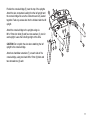
Position the console bridge (5) near the top of the uprights.
Attach the wire connectors leading from the left upright and
the console bridge. Be sure the connectors are fully seated
together. Feed any excess wire into the hollow inside the left
upright.
Attach the console bridge to the uprights using six
M8 x 15mm zinc bolts (6) and four star washers (3), two for
each upright. Leave the bolts finger-tight at this time.
CAUTION: Do not pinch the wire when attaching the left
upright to the console bridge.
Attach one handlebar extension (7) on each side of the
console bridge, using two black M8 x 15mm (8) bolts and
two star washers (3) each.
11
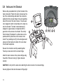
2.4
INSTALLING
THE
CONSOLE
Remove the pre-installed bolt (A) from the back of the
main console (B). Position the main console near the
top of the console bridge and attach the connectors
leading from the console bridge to the corresponding
tabs on the back of the main console. The wires are
color wrapped to match colored tabs on the main console circuit board. The main console harness (C)
wrapped in a green sleeve corresponds with the
green tab on the console circuit board. The Activity
Zone harness (D) wrapped in a yellow sleeve corresponds with the yellow tab on the console circuit
board. The grounding wire (E) is the small green and
yellow wire that inserts onto either of the two metal
circuit board receptacles.
Be sure the connectors are fully seated together.
Feed any excess wire into the console bridge.
Attach the main console to the console bridge using
three M8 x 15mm zinc bolts (9). Tighten the bolts
securely.
CAUTION: Do not pinch the wires when attaching the main console to the console bridge.
Securely tighten all the bolts that were left finger-tight.
12
2.5
ATTACHING
THE
POWER CORD
Insert the female plug of your treadmill’s power cord into the male outlet next to your treadmill’s power switch.
Note: F3 treadmills shipped in the USA and Canada are supplied with a North American line cord. 230V F3 treadmills
shipped outside North America are supplied with three line cords: a UK line cord, a continental line cord, and an
Australian line cord. Attach the cord suited to your area.
2.6
CALIBRATION
Before using your treadmill please follow the calibration instructions below. Please stand to the side of your treadmill
during calibration.
1.
Turn treadmill on, or if on press the RESET key.
2.
The console will display "PLEASE WAIT" or "WAIT".
3.
When "PLEASE WAIT" or "WAIT" disappears and the screen is blank press and hold the PAUSE key until "DIAGNOSTICS"
appears.
4.
Use the arrow keys to scroll through the diagnostics menu to "CALIBRATION" or "CALIB".
5.
Press enter to select "CALIBRATION" or "CALIB".
6.
Press the START key located on the lower control pad to begin calibration.
7.
Your treadmill will now automatically cycle through a series of tests including speed and incline adjustments in order to complete calibration.
8.
When successfully completed the console will display "PASS"
***If there was an error during calibration the console will display "FAIL".
***If a failure occurred press STOP twice and restart the process at Step 1.
***If failure occurs again take note of the error number display and contact Life Fitness customer support at 1-800-351-3737
(U.S.A. and Canada).
9.
Upon successful completion press the RESET key three times to exit calibration mode.
13
3
SETUP
ELECTRICAL POWER REQUIREMENTS
Most Life Fitness Treadmills are intended for use on a normal 120 volt circuit in the United States and Canada. Below is
a table that provides the current rating for this product based on supply voltage. Make sure that the treadmill model
supports the proper line voltage for the installation location before plugging into the outlet.
Supply Voltage (VAC)
120
230
Frequency (Hz)
50 / 60
50 / 60
Maximum Current (Amps)
12
6.3
ELECTRICAL GROUNDING REQUIREMENTS
This Life Fitness product must be properly grounded. If the unit malfunctions or breaks down, proper grounding
provides the path of least resistance for the electric current, which reduces the risk of shock to anyone touching or using
the equipment. Each unit is equipped with an electrical cord, which includes an equipment grounding conductor and a
grounding plug. The plug must be inserted into an outlet that has been properly installed and grounded in accordance
with all local codes and ordinances. A temporary adapter must not be used to connect this plug to a two-pole receptacle
in North America. If a properly grounded, correct amperage outlet is not available, a qualified electrician must install one.
DANGER: A risk of electrical shock may result from improper connection of the equipment’s grounding conductor. Check
with a qualified electrician if you are unsure about proper grounding techniques. Do not modify the plug provided with
this product. If it will not fit an electrical outlet, have a proper outlet installed by a qualified electrician.
TURNING
THE
UNIT ON
To turn the treadmill on, locate the ON/OFF power switch at the front of the treadmill near the power cord and turn it ON.
14
HOW TO STABILIZE THE LIFE FITNESS TREADMILL
After placing the unit where it will be used, check its stability. If there is even a
slight rocking motion or the unit is not stable, determine which stabilizing leg is
not resting on the floor. To adjust, turn the STABILIZING LEG (A) until the
rocking motion ceases and both stabilizing legs rest firmly on the floor.
NOTE: If excessive vibration occurs during use, adjust the height of the
levelers closer to the uprights. Do not adjust the height of the levelers further
from the uprights.
NOTE: It is extremely important that the stabilizing leg be correctly adjusted for
proper operation.
CHECKING
THE
BELT
After the treadmill has been installed and stabilized, the belt must be checked to confirm proper tracking. First, ensure
the power cord is plugged into a suitable outlet, as described in the Electrical Requirements section. Then turn the
treadmill on. Stand on the side rails of the treadmill and straddle the belt. To start the belt, press the Start/Enter key, then
press the speed up arrow key until the treadmill reaches 4.0 MPH. If the striding belt appears off-center, see the
instructions on the How to Center the Striding Belt page in the Service and Technical Data section.
15
RAISING AND LOWERING
THE
DECK
The treadmill’s deck can be folded up when not in use. To do so, make sure that the incline is set to 0%, then simply
grab the deck and lift it until it snaps into place.
To lower the deck again, squeeze the release handle (A) and slowly lower it to the ground. Make sure the deck is completely lowered before using the treadmill.
NOTE: When raising and lowering deck, take care not to get hands or skin caught in the treadmill’s pinch points (C).
POWER SWITCH
Located on the front panel at the base of the treadmill, the ON/OFF switch has two positions - "I" (one) for ON and "0"
(zero) for OFF.
MOVING
THE
TREADMILL
Turn the treadmill off and disconnect its power cord, then raise its deck.
NOTE: If adjustments were made to the front levelers during setup, make sure to tighten the levelers snug against the
base frame before moving.
The treadmill may now be moved on its front platform wheels by pushing and pulling on its handrails. Do not attempt to
move the treadmill by pushing or pulling on the deck or deck support tubing.
IMMOBILIZING THE TREADMILL
When it is necessary to immobilize the treadmill, press and hold both the down arrow and the enter key on the console.
16
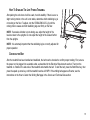
CENTERING THE BELT
After the treadmill has been installed and leveled, the belt
must be checked to confirm proper tracking. First, plug the
power cord into a suitable outlet. See the topic titled Electrical
Requirements, which appears earlier in this section, for
details. Then, turn the treadmill ON.
Stand on the siderails of the treadmill and straddle the belt.
Press the START key and increase the speed to 4.0-mph
(6.4 kph) using the SPEED UP ARROW key.
If the striding belt moves to the right, turn the right tension bolt
(D) a quarter-turn clockwise with provided quarter-inch Allen
wrench, and then turn the left tension bolt a quarter-turn
counter-clockwise (see figure). This sets the striding belt tracking back to the center of the roller.
If the striding belt moves to the left, turn the left tension bolt a quarter-turn clockwise and then turn the right tension bolt
a quarter-turn counter-clockwise to start striding belt tracking back to the center of the roller.
Repeat adjustments until the striding belt appears centered. The belt should be centered on the roller with an equal distance on both sides from belt to roller. Allow the machine to continue running for several minutes to observe if the tracking remains stabilized.
NOTE: Do not exceed one full turn of the adjusting screws in either direction.If, after one full turn, the belt does not track
properly, contact Customer Support Services. The phone numbers are listed in Section 5.4, titled How to Obtain Product
Service.
17
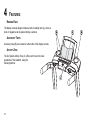
4
FEATURES
READING RACK
The display console design includes a built-in reading rack (A), where a
book or magazine can be placed during a workout.
ACCESSORY TRAYS
Accessory trays (B) are located on either side of the display console.
ACTIVITY ZONE
The Go System Activity Zone (C) offers control over the basic
operations of the treadmill, using the
following buttons:
18
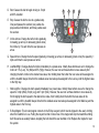
D. Start: Causes the belt to begin moving at .5 mph
and 0% elevation.
E. Stop: Causes the belt to slow to a gradual stop.
One push pauses the workout, two pushes displays workout information, and three pushes reset
the workout.
F.
Incline Arrows: Change the belt’s incline gradually,
increasing (up arrow) or decreasing (down arrow)
the incline by .5% each time the user presses an
arrow.
G. Speed Arrows: Change the belt’s speed gradually, increasing (up arrow) or decreasing (down arrow) the speed by .1
mph each time the user presses an arrow.
H. Low/Med/High: Changes the belt’s incline immediately to a preset value. Initially these buttons are set to change the
incline to 1.5% (Low), 3% (Mid) and 5% (High). However, the user can set these buttons to new values by first
changing the belt’s incline to the desired new value, then holding down the button the new value will be assigned to
until the treadmill beeps. Note that the smallest value must always be assigned to the Low key and the highest value
to the High key.
I.
Walk/Jog/Run: Changes the belt’s speed immediately to a preset value. Initially these buttons are set to change the
speed to 3 mph (Walk), 5 mph (Jog) and 7 mph (Run). However, the user can set these buttons to new values by
first changing the belt’s speed to the desired new value, then holding down the button the new value will be
assigned to until the treadmill beeps. Note that the smallest value must always be assigned to the Walk key and the
highest value to the Run key.
J.
E-Stop Magnet: This circular magnet connects to the E-Stop Lanyard, which must be clipped to the user’s clothing
when the treadmill is in use. Pulling the lanyard so that it comes free of the magnet will stop the treadmill’s striding
belt; this serves as a safety feature, stopping the belt should the user stumble or fall. Replace the magnet to reset
the system.
19
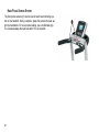
HAND PULSE SENSOR SYSTEM
The hand pulse sensors (K) are the built-in heart rate monitoring system on the treadmill. During a workout, grasp the sensors that are set
into the handlebars. For an accurate reading, use a comfortable grip.
The console displays the heart rate after 15 to 20 seconds.
20
5
SERVICE AND TECHNICAL DATA
5.1
TROUBLESHOOTING
1.
Why do I hear a rubbing noise from the belt?
a.
2.
The console display looks strange or has an error message and is not functioning.
a.
3.
Unplug the unit to reset the console and then plug it back in. Do this multiple times if the console error
message still appears. If the problem still exists please call customer service.
My treadmill keeps going into a mode where the message center displays "Press Enter to Unlock"
a.
4.
The belt could be off-centered. Please see the section entitled How to Adjust and Tension the Striding Belt.
Your treadmill is in safety mode and this lock feature is to protect someone from accidentally pressing a
button they are not suppose to and starting the treadmill. You can go into the Settings Menu to disable this
feature or extend the length of the time it takes for this feature to turn on. Please refer to the console User
Manual for more on this feature.
There is a lot of noise coming from the motor area.
a.
First make sure that the motor cover is properly installed and screwed down. If there continues to be noise
please contact customer service.
21
5.
My contact heart rate sensors are not reading my heart rate correctly.
a.
If the heart rate reading is erratic or missing, do the following:
i.
Dry the hands if necessary to prevent slipping.
ii.
Apply hands to all four sensors; two in each hand.
iii. Grasp the sensors firmly.
iv. Apply constant pressure around the sensors.
6.
My belt is tracking off to the left or right.
a.
7.
The belt seems to slip when I run on it.
a.
8.
Make sure the treadmill is at 0% incline before folding it up. If it is not at 0%, it will not lock.
My treadmill will not unfold.
a.
22
You will need to tighten the belt to the rear roller. Please see the section entitled How to Adjust and Tension
the Striding Belt.
My treadmill will not lock when I fold it up.
a.
9.
Please see the section entitled How to Adjust and Tension the Striding Belt.
Make sure you pull the release lever located on the top left side of the deck. If this problem persists please
contact customer service.
10. My treadmill will not turn on.
a.
Make sure that the treadmill’s power cord is connected to the treadmill at one end and is plugged into a
power outlet at the other. Also, make sure that the power switch is pushed to on. The power switch is located on the front of the treadmill right below the motor cover.
11. The handrails on my treadmill wobble.
a.
Make sure to tighten all of the bolts that are on the uprights and handlebars.
12. My treadmill shakes a lot when I run on it.
a.
Turn off the treadmill and make sure all assembly hardware is tightened. If shaking still occurs, adjust the
levelers under the frame until the shaking ceases.
23
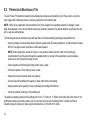
5.2
PREVENTATIVE MAINTENANCE TIPS
The Life Fitness F3 treadmill is backed by the engineering excellence and reliability of Life Fitness and is one of the
most rugged and trouble-free pieces of exercise equipment on the market today.
NOTE: Safety of the equipment can be maintained only if the equipment is examined regularly for damage or wear.
Keep the equipment out of use until defective parts are repaired or replaced. Pay special attention to parts that are subject to wear, as outlined below.
The following preventive maintenance tips will keep the Life Fitness treadmill operating at peak performance:
• Clean the display console and all exterior surfaces regularly with mild soap and water or a mild household cleaner.
DO NOT use paper towels, ammonia or acid based cleaners.
NOTE: When cleaning the exterior of the unit, a non-abrasive cleaner and soft cotton cloth are strongly
recommended. At no time should cleaner be applied directly to any part of the equipment; use non-abrasive
cleaner on a soft cloth and then wipe the unit.
• Check operation of the Emergency Stop System once a week.
• Check the operation of the Stop key once a week.
• Inspect and vacuum the area under unit regularly.
• Vacuum around the striding belt regularly to keep debris from accumulating.
• Inspect exterior parts regularly for wear, particularly the striding belt and deck.
• Check the position (centering) of the striding belt.
The optimum operating position of the striding belt is from .5" (12mm) to 1" (25mm) from either side of the frame. If the
striding belt travels beyond this position, see How to Adjust and Tension the Striding Belt or contact Life Fitness
Customer Support Services for proper alignment instructions, 1-800-328-9714 (USA).
24
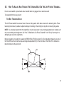
5.3
HOW TO ADJUST AND TENSION THE STRIDING BELT ON THE LIFE FITNESS TREADMILL
Do not move treadmill or place hands under treadmill while it is plugged into an electrical outlet!
Tool required: 6mm hex key wrench
THE BELT TENSIONING BOLTS
The Life Fitness treadmill has access holes in the rear roller guards, which allow access to the tensioning bolts. These
tensioning bolts make it possible to adjust tracking and centering of the striding belt (A) without removing the guards.
NOTE: It is extremely important that the treadmill be correctly leveled prior to any tracking adjustments. An unstable unit
may cause striding belt misalignment. See "How To Stabilize the Life Fitness Treadmill" in the "Set Up" section prior to
attempting any rear roller adjustments.
Before proceeding, it is helpful to visualize the REAR ROLLER (B) pivot point (C). Each adjustment made to one side of
the ROLLER must be met with an equal and opposite adjustment (D) to the other side of the ROLLER to maintain an
ideal belt tension at the pivot point.
25
TRACKING (CENTERING) AN EXISTING OR NEW STRIDING BELT
1
Locate the two access holes to the belt tensioning bolts on each of the rear roller guards.
2
Stand on the sides of the treadmill and straddle the belt, not standing on it. Enter the MANUAL Workout and set the
belt speed to run at 4.0 mph (6,4 kph).
3
If the striding belt has moved to the right, turn the right tension bolt 1/4 turn clockwise with provided 6mm hex key
wrench, and then turn the left tension bolt 1/4 turn counter-clockwise to start striding belt tracking back to center of
roller.
4
If the striding belt has moved to the left, turn the left tension bolt 1/4 turn clockwise and then turn the right tension
bolt 1/4 turn counter-clockwise to start striding belt tracking back to center of roller. Repeat adjustments until striding
belt appears centered. Allow machine to continue running for several minutes to observe if tracking remains stabilized.
NOTE: Do not exceed one full turn of the adjusting screws in either direction. If after one full turn the belt does not track
properly, contact Customer Support Services. The phone numbers are listed in "How to Obtain Product Service."
TENSIONING AN EXISTING STRIDING BELT
Under normal usage, the treadmill striding belt may stretch slightly. If the belt starts to slip during use, take the steps listed below to correct the tension.
1
Using the STOP key, stop the treadmill.
2
Turn the belt tensioning bolts clockwise a quarter-turn per side to tension the belt. Do not exceed one full turn (four
quarter-turns per side).
3
Set the treadmill at 2.0-mph (3,2 kph) and get on to make sure the belt no longer slips. Also, check the striding belt’s
tracking. If the striding belt drifts to the left or right see Tracking (Centering) an Existing or New Striding Belt.
NOTE: Do not over-tighten the tensioning bolts while making belt adjustments. Over-tightening of bolts may over stretch
and damage the striding belt or roller bearings. Do not exceed one full turn of either bolt in either direction.
26
5.4
HOW TO OBTAIN PRODUCT SERVICE
1. Verify the symptom and review the operating instructions.
2. Locate and document the serial numbers of the base and the console. The base’s serial number is located on front
of the treadmill near the power switch and the console serial number is located on the back surface of the console.
3. Contact the nearest Life Fitness Customer Support Services Group:
For Product Service within the United States and Canada:
Telephone: (+1) 847.451.0036
FAX: (+1) 847.288.3702
Toll-free telephone: 800.351.3737
For Product Service
Internationally:
Life Fitness Europe GmbH
Telephone: (+49) 089.317.751.66
FAX: (+49) 089.317.751.38
Life Fitness (UK) LTD
Telephone: (+44) 1353.665507
FAX: (+44) 1353.666018
Life Fitness Atlantic BV
Life Fitness Benelux
Telephone: +31 (0) 180 64 66 66
FAX: +31 (0) 180 64 66 99
Life Fitness Italia S.R.L.
Telephone: (+39) 0472.835.470
FAX: (+39) 0472.833.150
Toll-free telephone: 800.438836
Life Fitness Latin America
and Caribbean
Telephone: (+1) 847.288.3964
FAX: (+1) 847 288.3886
Life Fitness Vertriebs GmbH
Telephone: (+43) 1615.7198
FAX: (+43) 1615.7198.20
Life Fitness Brazil
Telephone: (+55) 11.7295.2217
FAX: (+55) 11.7295.2218
Life Fitness Asia Pacific Ltd
Telephone: (+852) 2891.6677
FAX: (+852) 2575.6001
Life Fitness Japan
Telephone: (+81) 3.3359.4306
FAX: (+81) 3.3359.4307
Life Fitness Iberia
Telephone : (+34) 93 672 4660
FAX : (+34) 93 672 4670
27
6
SPECIFICATIONS
LIFE FITNESS F3 TREADMILL SPECIFICATIONS
Designed use:
Home
Maximum user weight:
350 pounds / 159 kilograms
Speed range:
0.5 - 10.0 mph in 0.1 increments
Elevation range:
0%-12% (in 0.5% increments)
Motor:
3 HP continuous duty DC
Rollers:
Front: 2.6" (67mm) precision crowned
Back: 2.0" (50mm) precision crowned
Belt:
55" Length x 20" Width
(147cm Length x 50cm Width), multi-ply
Deck:
Flex Deck cushioning, not reversible
Handrails:
Ergo Crossbar with side handrails.
Accessory tray:
Standard, designed into system
Warranty:
10 years motor, 5 years parts,
3 years console, 1 year labor, and
lifetime on frame and springs
28
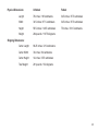
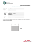
Physical Dimensions:
Unfolded
Folded
Length:
78 inches / 198 centimeters
34.5 inches / 87.5 centimeters
Width:
34.5 inches / 87.5 centimeters
34.5 inches / 87.5 centimeters
Height:
58.5 inches / 148.5 centimeters
75 inches / 190.5 centimeters
Weight:
264 pounds / 119.75 kilograms
Shipping Dimensions:
Carton Length:
86.25 inches / 219 centimeters
Carton Width:
33 inches / 84 centimeters
Carton Height:
14 inches / 35.5 centimeters
Total Weight:
291 pounds / 132 kilograms
29
7
WARRANTY INFORMATION
WHAT IS COVERED:
This Life Fitness consumer product ("Product") is warranted to be free of all defects in material and workmanship.
WHO IS COVERED:
The original purchaser or any person receiving a newly purchased Product as a gift from the original purchaser.
HOW LONG IS IT COVERED:
Residential: All electrical and mechanical components and labor are covered, after the date of purchase, as listed on the chart below.
Non-Residential: Warranty void (this Product is intended for residential use only).
WHO PAYS SHIPPING & INSURANCE FOR SERVICE:
If the Product or any warranted part must be returned to a service facility for repairs, Life Fitness will pay all shipping and insurance
charges during the warranty period (within the United States only). The purchaser is responsible for shipping and insurance charges
after the warranty has expired.
WHAT WE WILL DO TO CORRECT COVERED DEFECTS:
We will ship to you any new or rebuilt replacement part or component, or, at our option, replace the Product. Such replacement parts
are warranted for the remaining portion of the original warranty period.
WHAT IS NOT COVERED:
Any failures or damage caused by unauthorized service, misuse, accident, negligence, improper assembly or installation, debris
resulting from any construction activities in the Product's environment, rust or corrosion as a result of the Product's location, alterations
or modifications without our written authorization or by failure on your part to use, operate and maintain the Product as set out in your
User Manual ("Manual"). All terms of this warranty are void if this Product is moved beyond the continental borders of the United States
of America (excluding Alaska, Hawaii and Canada) and are then subject to the terms provided by that country's local authorized
Life Fitness Representative.
30
WHAT YOU MUST DO:
Retain proof of purchase (our receipt of the attached registration card assures registration of purchase information but is not required);
use, operate and maintain the Product as specified in the Manual; notify Customer Service of any defect within 10 days after discovery of the defect; if instructed, return any defective part for replacement or, if necessary, the entire Product for repair.
Life Fitness reserves the right to decide whether or not a product is to be returned for repair.
USER MANUAL:
It is VERY IMPORTANT THAT YOU READ THE MANUAL before operating the Product. Remember to perform the periodic maintenance
requirements specified in the Manual to assure proper operation and your continued satisfaction.
PRODUCT REGISTRATION:
Register online at www.lifefitness.com/registration. Our receipt assures that your name, address and date of purchase are on file
as a registered owner of the Product. Failure to return the card will not affect your rights under this warranty. Being a registered owner
assures coverage in the event you lose your proof of purchase. Please retain your proof of purchase, such as your bill of sale or receipt.
HOW TO GET PARTS & SERVICE:
Simply call Customer Service at 1-800-351-3737 or (+1) 847-288-3300, Monday through Friday from 8:00 a.m. to 5:00 p.m. Central
Standard Time, and tell them your name, address and the serial number of your Product (consoles and frames may have separate
serial numbers). They will tell you how to get a replacement part, or, if necessary, arrange for service where your Product is located.
EXCLUSIVE WARRANTY:
THIS LIMITED WARRANTY IS IN LIEU OF ALL OTHER WARRANTIES OF ANY KIND EITHER EXPRESSED OR IMPLIED,
INCLUDING BUT NOT LIMITED TO THE IMPLIED WARRANTIES OF MERCHANTABILITY AND FITNESS FOR A PARTICULAR
PURPOSE, AND ALL OTHER OBLIGATIONS OR LIABILITIES ON OUR PART. We neither assume nor authorize any person to
assure for us any other obligation or liability concerning the sale of this Product. Under no circumstances shall we be liable under
this warranty, or otherwise, of any damage to any person or property, including any lost profits or lost savings, for any special, indirect,
secondary, incidental or consequential damages of any nature arising out of the use of or inability to use this Product. Some states
do not allow the exclusion or limitation of implied warranties or of liability for incidental or consequential damages, so the above
limitations or exclusions may not apply to you. Warranties may vary outside the U.S. Contact Life Fitness for details.
31
CHANGES IN WARRANTY NOT AUTHORIZED:
No one is authorized to change, modify or extend the terms of this limited warranty.
EFFECT OF U.S. STATE LAWS:
This warranty gives you specific legal rights and you may have other rights which vary from state to state.
32
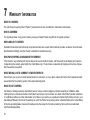
MODEL
LIFETIME
10 YEARS
5 YEARS
3 YEARS
1 YEAR
F3
Frame &
Lifesprings
Motor
Electrical Parts &
Mechanical Parts
Console Parts
Labor
STAIRCLIMBERS | GYM SYSTEMS
5100 N. RIVER ROAD, SCHILLER PARK, ILLINOIS 60176
LIFEFITNESS.COM
©2006 Life Fitness, a division of Brunswick Corporation. All rights reserved. Life Fitness and Lifecycle are a registered trademarks of Brunswick Corporation. 8119901 Rev. A-1 (08.06)
Life Fitness offers a full line of premier fitness equipment for the home.
TOTAL-BODY ELLIPTICAL CROSS-TRAINERS | TREADMILLS | LIFECYCLE® EXERCISE BIKES