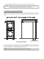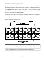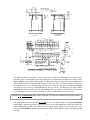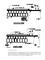
1
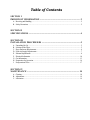
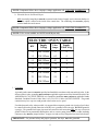
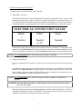
ADG-215/ADG-220/ADG-230/ADG-235
Installation Manual
WARNING: For your safety the information in
this manual must be followed to minimize the
risk of fire or explosion or to prevent property
damage, personal injury or death.
AVERTISSEMENT: Assurez-vous de bien
suivre les instructions données dans cette notice
pour réduire au minimum le risque d’incendie
ou d’explosion ou pour éviter tout dommage
matériel, toute blessure ou la mort.
— Do not store or use gasoline or other flammable
vapors and liquids in the vicinity of this or any
other appliance.
— Ne pas entreposer ni utiliser d’essence ni
d’autres vapeurs ou liquides inflammables à
proximité de cet appareil ou de tout autre
appareil.
— WHAT TO DO IF YOU SMELL GAS:
• Do not try to light any appliance.
• Do not touch any electrical switch; do not
use any phone in your building.
• Clear the room, building or area of all
occupants.
• Immediately call your gas supplier from a
neighbor’s phone. Follow the gas supplier’s
instructions.
• If you cannot reach your gas supplier, call
the fire department.
— Installation and service must be performed by a
qualified installer, service agency or the gas
supplier.
— QUE FAIRE SI VOUS SENTEZ UNE ODEUR
DE GAZ:
• Ne pas tenter d’allumer d’appareils.
• Ne touchez à aucun interrupteur. Ne pas
vous servir des téléphones se trouvant dans
le bâtiment.
• Évacuez la pièce, le bâtiment ou la zone.
• Appelez immédiatement votre fournisseur
de gaz depuis un voisin. Suivez les
instructions du fournisseur.
• Si vous ne pouvez rejoindre le fournisseur
de gaz, appelez le service des incendies.
— L’installation et l’entretien doivent être assurés par
un installateur ou un service d’entretien qualifié
ou par le fournisseur de gaz.
For replacement parts, contact the reseller from which the dryer
was purchased or
American Dryer Corporation
88 Currant Road
Fall River MA 02720-4781
Telephone: (508) 678-9000 / Fax: (508) 678-9447
e-mail: [email protected]
www.amdry.com
121201tcosta
ADC Part No. 112115
Retain This Manual In A Safe Place For Future Reference
American Dryer Corporation products embody advanced concepts in engineering, design, and safety. If this product is
properly maintained, it will provide many years of safe, efficient, and trouble-free operation.
ONLY qualified technicians should service this equipment.
OBSERVE ALL SAFETY PRECAUTIONS displayed on the equipment or specified in the installation manual included with
the dryer.
The following “FOR YOUR SAFETY” caution must be posted near the dryer in a prominent location.
FOR YOUR SAFETY
POUR VOTRE SÉCURITÉ
Do not store or use gasoline or
other flammable vapors and
liquids in the vicinity of this or
any other appliance.
Ne pas entreposer ni utiliser d’essence
ni d’autres vapeurs ou liquides
inflammables à proximité de cet
appareil ou de tout autre appareil.
We have tried to make this manual as complete as possible and hope you will find it useful. ADC reserves the right to make
changes from time to time, without notice or obligation, in prices, specifications, colors, and material, and to change or
discontinue models. The illustrations included in this manual may not depict your particular dryer exactly.
Important
For your convenience, log the following information:
DATE OF PURCHASE________________________________ MODEL NO. __________________________________________
RESELLER’S NAME ________________________________________________________________________________________
Serial Number(s)
________________________________________________________________________________________
________________________________________________________________________________________
________________________________________________________________________________________
Replacement parts can be obtained from your reseller or the ADC factory. When ordering replacement parts from the factory,
you can FAX your order to ADC at (508) 678-9447 or telephone your order directly to the ADC Parts Department at (508)
678-9000. Please specify the dryer model number and serial number in addition to the description and part number, so that
your order is processed accurately and promptly.
“IMPORTANT NOTE TO PURCHASER”
Information must be obtained from your local gas supplier on the instructions
to be followed if the user smells gas. These instructions must be posted in a
prominent location near the dryer.
IMPORTANT
YOU MUST DISCONNECT AND LOCKOUT THE ELECTRIC SUPPLY AND THE GAS
SUPPLY BEFORE ANY COVERS OR GUARDS ARE REMOVED FROM THE
MACHINE TO ALLOW ACCESS FOR CLEANING, ADJUSTING, INSTALLATION, OR
TESTING OF ANY EQUIPMENT PER OSHA (Occupational Safety and Health
Administration) STANDARDS.
“Caution: Label all wires prior to
disconnection when servicing controls. Wiring
errors can cause improper operation.”
«Attention: Au moment de l’entretien des
commandes, étiquetez tous les fils avant de
les débrancher. Des erreurs de câblage
peuvent entraîner un fonctionnement
inadéquat et dangereux.»
CAUTION
DRYERS SHOULD NEVER BE LEFT UNATTENDED WHILE IN OPERATION.
WARNING
CHILDREN SHOULD NOT BE ALLOWED TO PLAY ON OR NEAR THE DRYER(S).
CHILDREN SHOULD BE SUPERVISED IF NEAR DRYERS IN OPERATION.
FOR YOUR SAFETY
DO NOT DRY MOP HEADS IN THE DRYER.
DO NOT USE DRYER IN THE PRESENCE OF DRY CLEANING FUMES.
WARNING
UNDER NO CIRCUMSTANCES should the dryer door switch or heat circuit safety
devices ever be disabled.
WARNING
The dryer must never be operated with any of the back guards, outer tops, or service
panels removed. PERSONAL INJURY OR FIRE COULD RESULT.
WARNING
DRYER MUST NEVER BE OPERATED WITHOUT THE LINT FILTER/SCREEN IN
PLACE, EVEN IF AN EXTERNAL LINT COLLECTION SYSTEM IS USED.
IMPORTANT
PLEASE OBSERVE ALL SAFETY PRECAUTIONS displayed on the equipment and/or
specified in the installation manual included with the dryer.
Dryer must not be installed or stored in an area where it will be exposed to water or weather.
The wiring diagram for the dryer is located in the front electrical control box area.
Table of Contents
SECTION I
IMPORTANT INFORMATION .......................................................................... 2
A. Receiving and Handling ............................................................................................................... 2
B. Safety Precautions ...................................................................................................................... 2
SECTION II
SPECIFICATIONS .............................................................................................. 4
SECTION III
INSTALLATION PROCEDURES ...................................................................... 5
A.
B.
C.
D.
E.
F.
G.
H.
I.
Unpacking/Set Up ...................................................................................................................... 5
Location of the Dryer.................................................................................................................. 5
Dryer Enclosure Requirements .................................................................................................... 6
Fresh Air Supply Requirements ................................................................................................... 7
Exhaust Requirements ................................................................................................................. 8
Electrical Information ................................................................................................................ 10
Gas Information........................................................................................................................ 13
Preparation for Operation ......................................................................................................... 16
Preoperational Tests ................................................................................................................. 17
SECTION IV
MAINTENANCE ............................................................................................... 18
A. Cleaning ................................................................................................................................... 18
B. Adjustments ............................................................................................................................. 19
C. Lubrication ............................................................................................................................... 19
SECTION I
IMPORTANT INFORMATION
A. RECEIVING AND HANDLING
The dryer is shipped with a protective polyethylene cover and protective corners and is enclosed in a cardboard
carton as a means of protection in transit. Upon delivery, the shipping carton and wooden skid should be visually
inspected for shipping damage. If the carton or wooden skid is damaged, inspect further.
Dryers damaged in shipment:
1. ALL dryers should be inspected upon receipt and before they are signed for.
2. If there is suspected damage or actual damage, the trucker’s receipt should be so noted.
3. If the dryer is damaged beyond repair, it should be refused. Those dryers, which were not damaged in a
damaged shipment, should be accepted, but the number received and number refused must be noted on the
receipt.
4. If you determine that the dryer has been damaged after the trucker has left your location, you should call
your local freight terminal immediately and request an inspection and freight claim form. The freight
company considers this concealed damage. This type of freight claim is very difficult to get paid and
becomes extremely difficult when more than a day or two passes after the freight was delivered.
5. If you need assistance in handling the situation, please call American Dryer Corporation.
IMPORTANT: The dryer should be transported and handled in an upright position at ALL
times.
B. SAFETY PRECAUTIONS
1. DO NOT store or use gasoline or other flammable vapors and liquids in the vicinity of this or any other
appliance.
2. Purchaser/user should consult the local gas supplier for proper instructions to be followed in the event the
user smells gas. The instructions should be posted in a prominent location.
3. Dryer must be exhausted to the outdoors.
4. Although the American Dryer is a very versatile dryer, there are some articles that, due to fabric composition
or cleaning method, should not be dried in it.
WARNING: Dry only water washed fabrics. DO NOT dry articles spotted or washed in dry
cleaning solvents, a combustible detergent, or “all purpose” cleaners.
FIRE OR EXPLOSION COULD RESULT.
2
WARNING: DO NOT dry rags or articles coated with gasoline, kerosene, paint, wax, or grease.
FIRE OR EXPLOSION COULD RESULT.
WARNING: DO NOT dry mop heads. Contamination by wax or flammable solvents will create
a fire hazard.
WARNING: DO NOT use heat for drying articles that contain plastic, foam, sponge rubber, or
similarly textured rubberlike materials. Drying in a heated basket (tumbler) may
damage plastics or rubber and may be a fire hazard.
5. A program should be established for the inspection and cleaning of the lint in the burner area and exhaust
ductwork. The frequency of inspection and cleaning can best be determined from experience at each location.
WARNING: The collection of lint in the burner area and exhaust ductwork can create a potential
fire hazard.
6. For personal safety, the dryer must be electrically grounded in accordance with local codes and/or the
National Electrical Code ANSI/NFPA NO. 70-LATEST EDITION or in Canada, the Canadian Electrical
Codes Parts 1 & 2 CSA C22.1-1990 or LATEST EDITION.
NOTE: Failure to do so will VOID THE WARRANTY.
7. UNDER NO CIRCUMSTANCES should the dryer door switch or heat circuit safety devices ever be
disabled.
WARNING: PERSONAL INJURY OR FIRE COULD RESULT.
8. READ AND FOLLOW ALL CAUTION AND DIRECTION LABELS ATTACHED TO THE
DRYER.
3
SECTION II
SPECIFICATIONS
NOTE: ADC reserves the right to make changes in specifications at any time without notice or
obligation.
4
SECTION III
INSTALLATION PROCEDURES
Installation should be performed by competent technicians in accordance with local and state codes. In the
absence of these codes, the installation must conform to applicable American National Standards: ANSI Z223.1LATEST EDITION (National Fuel Gas Code) or ANSI/NFPA NO. 70-LATEST EDITION (National Electrical
Code) or in Canada, the installation must conform to applicable Canadian Standards: CAN/CGA-B149.1-M91
(Natural Gas) or CAN/CGA-B149.2-M91 (Liquid Propane [L.P.] Gas) or LATEST EDITION (for General
Installation and Gas Plumbing) or Canadian Electrical Codes Parts 1 & 2 CSA C22.1-1990 or LATEST EDITION
(for Electrical Connections).
A. UNPACKING/SET UP
Remove shipping carton, polyethylene cover, and protective shipping corners from dryer.
NOTE: The access keys to the coin box, control (upper service) door, and lint (lower service)
door are shipped in the upper basket (tumbler) and should be removed and put in a safe
place.
The dryer can be moved to its final location while still attached to the skid or with the skid removed. To un-skid
the dryer, locate and remove the four (4) bolts securing the base of the dryer to the wooden skid. Two (2) are
located at the rear of the base, and two (2) are located in front. Once the bolts are removed, slide the dryer off the
skid.
With the skid removed, to make it easier to slide the dryer into its final position, slightly lower ALL four (4)
leveling legs, so that the dryer will slide on the legs instead of the base frame. The dryer is equipped with four (4)
leveling legs, one (1) at each corner of the dryer base.
B. LOCATION OF THE DRYER
Before installing the dryer, be sure the location conforms to local codes and ordinances. In the absence of such
codes or ordinances the location must conform with the National Fuel Gas Code ANSI.Z223.1 LATEST EDITION,
or in Canada, the installation must conform to applicable Canadian Standards: CAN/CGA-B149.1-M91 (Natural
Gas) or CAN/CGA-B149.2-M91 (L.P. Gas) or LATEST EDITION (for General Installation and Gas Plumbing).
1. The dryer must be installed on a sound level floor capable of supporting its weight. Carpeting must be
removed from the floor area that the dryer is to rest on.
IMPORTANT: “The dryer must be installed on noncombustible floors only.”
It is recommended that the rear of the dryer be positioned about 2 feet (0.61 meters) away from the nearest
obstruction (i.e., wall) for ease of installation, maintenance, and service.
2. The dryer must be installed with a proper exhaust duct connection to the outside.
5
3. The dryer must be installed with provisions for adequate combustion and make-up air supply.
CAUTION: This dryer produces combustible lint and must be exhausted to the outdoors. Every
6 months, inspect the exhaust ducting and remove any lint build up.
C. DRYER ENCLOSURE REQUIREMENTS
Bulkheads and partitions should be made of noncombustible materials and must be located a minimum of
6-inches (15.24 cm) above the dryer outer top, except along the front of the dryer which may be closed in if
desired.
6
LEAVE 18”-24” AT REAR OF DRYER
FOR MAINTENANCE & SERVICE
0” MIN DISTANCE TO
COMBUSTIBLE MATERIALS
Dryers may be positioned sidewall to sidewall. However, allowances should be made for the opening and closing
of the control and lint doors. It is suggested that the dryer be positioned about 2 feet (0.61 meters) away from the
nearest rear obstruction for ease of installation, maintenance, and service.
NOTE: Air considerations are important for proper and efficient operation.
6
D. FRESH AIR SUPPLY REQUIREMENTS
Air supply (make-up air) must be given careful consideration to assure proper performance of each dryer. An
unrestricted source of air for 800 cfm (22.65 cmm) is necessary for each dryer. An unrestricted air entrance from
the outdoors (atmosphere) of a minimum of 1-1/2 square feet (0.14 square meters) is required for each dryer.
This area must be enlarged if louvers or registers cover the opening. It is not necessary to have a separate
make-up air opening for each dryer. Common make-up air openings are acceptable. However, they must be set
up in such a manner that the make-up air is distributed equally to the dryers. The dryer must be installed with
provisions for adequate combustion and make-up air supply.
EXAMPLE: For a bank of eight (8) dryers, a total make-up air opening of 12 square feet (1.11 square meters) is
required. Two (2) openings measuring 2 feet x 3 feet (0.61 meters x 0.91 meters), (6 square feet
[0.56 square meters]) are acceptable.
Allowances must be made for remote or constricting passageways or where dryers are located at excessive
altitudes or predominately low pressure areas.
IMPORTANT: Make-up air must be provided from a source free of dry cleaning fumes.
Make-up air contaminated by dry cleaning fumes will result in irreparable damage
to motors and other dryer components.
NOTE: Component failure due to dry cleaning fumes VOIDS THE WARRANTY.
7
E. EXHAUST REQUIREMENTS
Exhaust ductwork should be designed and installed by a competent technician. Improperly sized ductwork will
create excessive back pressure which results in slow drying, increased use of energy, overheating of the dryer, and
shutdown of the burner by the airflow (sail) switches, burner hi-limits, or basket (tumbler) hi-heat protector
thermostats. The dryer must be installed with a proper exhaust duct connection to the outside.
CAUTION: This dryer produces combustible lint and must be exhausted to the outdoors.
CAUTION: IMPROPERLY SIZED OR INSTALLED EXHAUST DUCTWORK CAN
CREATE A POTENTIAL FIRE HAZARD.
Where possible, it is suggested to provide a separate exhaust duct for each dryer. The exhaust ductwork should
be laid out in such a way that the ductwork travels as directly as possible to the outdoors, with as few turns as
possible. It is suggested that the use of right angle turns in the ducting be avoided; use 30º or 45º angles instead.
The shape of the exhaust ductwork is not critical, so long as the minimum cross section area is provided.
If the exhaust ductwork is unusually long (over 20 feet [6.1 meters]) or has numerous elbows, the cross section
area of the ductwork must be increased in proportion to its length or the number of elbows in it. In calculating
duct size, the cross section area of a square rectangle duct must be increased 20 percent (20%) for each additional
20 feet (6.1 meters). The diameter of a round exhaust should be increased 10 percent (10%) for each additional
20 feet (6.1 meters). Each 90º elbow is equivalent to an additional 15 feet (4.57 meters), and each 45º elbow, an
additional 10 feet (3.05 meters).
The ductwork should be smooth inside with no projections from sheet metal screws or other obstructions, which
will collect lint. When adding ducts, the duct to be added should overlap the duct to which it is to be connected.
Also, inspection doors should be installed at strategic points in the exhaust ductwork for periodic inspection and
cleaning.
To protect the outside end of the horizontal ductwork from the weather, a 90º elbow bent downward should be
installed where the exhaust exits the building. (Refer to the illustration on the following page.) If the exhaust
ductwork travels vertically up through the roof, it should be protected from the weather by using a 180º turn to
point the opening downward. (Refer to the illustration on the following page.) In either case, allow at least twice
the diameter of the duct between the duct opening and nearest obstruction.
IMPORTANT: DO NOT use screens, louvers, or caps on the outside opening of the exhaust
ductwork.
1. Multiple Dryer Venting
If it is not feasible to provide separate exhaust ducts for each dryer, ducts from individual dryers may be
channeled into a “common main duct.” (Refer to the illustration on the following page.) The individual
ducts should enter the bottom or side of the main duct at an angle not more than 45º in the direction of
airflow. The main duct should be tapered, with the diameter increasing before each individual duct is
added. The cross section area should be 60 square inches (387.10 square centimeters) for each 8-inch
(20.32 cm) duct added.
8
The main duct may be any shape of cross section area, so long as the minimum cross section area is
provided. Figure 1, shown above, shows the minimum cross section area for multiple dryer venting. These
figures must be increased if more than twelve (12) dryers are connected to the same main (common) duct,
if the main duct end run is unusually long (20 feet [6.1 meters] or more), or if there are numerous elbows in
the main duct end run. In calculating duct size, the cross section area of a square or round duct must be
increased 20 percent (20%) for each additional 20 feet (6.1 meters). The diameter of a round exhaust
should be increased 10 percent (10%) for each additional 20 feet (6.1 meters). Each 90º elbow is equivalent
to an additional 15 feet (4.57 meters), and each 45º elbow, an additional 10 feet (3.05 meters).
NOTE: It is recommended that no more than four (4) dryers be connected to the same exhaust
duct.
It is suggested that the use of 90º turns be avoided; use 30º or 45º angles instead. The ductwork should be
smooth inside, with no projections from sheet metal screws or other obstructions, which will collect lint.
When adding ducts, the duct to be added should overlap the duct to which it is to be connected. Also,
inspection doors should be installed at strategic points in the exhaust ductwork for periodic inspection and
cleaning.
9
F. ELECTRICAL INFORMATION
1. Electrical Requirements
It is your responsibility to have ALL electrical connections made by a properly licensed and competent
electrician to assure that the electrical installation is adequate and conforms to local and state regulations or
codes. In the absence of such codes, ALL electrical connections, materials, and workmanship must conform
to the applicable requirements of the National Electrical Code ANSI/NFPA NO. 70-LATEST EDITION or
in Canada, the Canadian Electrical Codes Parts 1 & 2 CSA C22.1-1990 or LATEST EDITION.
IMPORTANT: Failure to comply with these codes or ordinances, and/or the requirements
stipulated in this manual can result in personal injury or component failure.
NOTE: Component failure due to improper installation will VOID THE WARRANTY.
It is recommended that a separate circuit servicing each basket (tumbler) compartment be provided. The
dryer must be connected with copper wire only. DO NOT use aluminum wire, which could cause a fire
hazard.
NOTE: The use of aluminum wire will VOID THE WARRANTY.
2. Electrical Service Specifications
a. Electrical Service for Gas Dryers
ELECTRICAL SERVICE
DRYER
SERVICE
NO. OF
PHASE
AMP DRAW
VOLTAGE
WIRES
PER TUMBLER
RECOMMENDED SPECS
WIRE
SIZE
BREAKER SIZE
PER TUMBLER
115
1
2
14
*
20A.
208/230
1
2
7
15A.**
208/230
3
3
5
*
*
15A.
* AWG Stranded Wire Type...size wire as per National Electrical Code or local codes.
** 2-Pole circuit breaker is required.
IMPORTANT: The dryer must be connected to the electrical supply shown on the data label,
located on the inside of the control door. In the case of 208 or 230 volts, the
supply voltage must match the electrical service specifications of the data label
exactly. The voltages 208 and 230 ARE NOT THE SAME. Should it be found
that the dryer was manufactured for operation at 230 volts and the service supply
voltage is 208 volts, (or vice versa), a slight wiring change is necessary at the
heat circuit transformers. These transformers are located in the front wiring box
and are used to step down the control (primary) voltage (i.e., 208 or 230) to 110
volts. The transformers are dual (primary) voltage, and they must be wired
accordingly. In the case of 208 volts, the yellow primary leads must be used, and
the red leads dead ended. For 230 volts, the red primary leads must be used, and
the yellow leads dead ended. Refer to the wiring diagram located in the front
wiring box.
10
NOTE: Component failure due to improper voltage application will VOID THE WARRANTY.
b. Electrical Service for Electric Dryers
ALL electrically heated dryers must be connected to the electrical supply service shown on the dryer’s
data label, which is affixed to the inside of the control door. The connecting wires must be properly
sized to handle the rated current.
NOTE: Component failure due to improper voltage application will VOID THE WARRANTY.
NOTE: 21 kw ovens available on AD-230 model dryers only.
ELECTRIC OVEN TABLE
KW
Supply
Voltage
Line
Amps
Supply
Cable Awg.
15
208/1-Phase
72
4
15
230/1-Phase
65
4
15
208/3-Phase
42
8
15
230/3-Phase
38
8
21
208/1-Phase
101
2
21
230/1-Phase
91
2
21
208/3-Phase
59
6
21
230/3-Phase
53
6
3. Grounding
A ground (earth) connection must be provided and installed in accordance with state and local codes. In the
absence of these codes, grounding must conform to applicable requirements of the National Electrical Code
ANSI/NFPA NO. 70-LATEST EDITION, or in Canada, the installation must conform to applicable Canada
Standards: Canadian Electrical Codes Parts 1 & 2 CSA C22.1-1990 or LATEST EDITION. The ground
connection may be to a proven earth ground at the location service panel.
For added personal safety, when possible, it is suggested that a separate ground wire (sized per local codes)
be connected from the ground connection of the dryer to a grounded cold water pipe. DO NOT ground to
a gas pipe. The grounded cold water pipe must have metal to metal connections ALL the way to electrical
ground. If there are any nonmetallic interruptions, such as, a meter, pump, plastic, rubber, or other insulating
connectors, they must be jumped with no. 4 copper wire and securely clamped to bare metal at both ends.
IMPORTANT: For personal safety and proper operation, the dryer must be grounded.
11
4. Electrical Connections for Gas Dryers
A wiring diagram is located inside the front wiring box.
a. Single-Phase (1ø) Dryers
The electrical connections for dryers manufactured for operation at single-phase (1ø) (2-wire) are made
through the top of the dryer, at the rear. The dryer is shipped with the three (3) connection leads (L1, L2
or N, and ground) for each basket (tumbler) compartment extending out of the top connector holes.
Each basket (tumbler) compartment has its own set of connecting leads and are electrically separate.
ELECTRICAL CONNECTION LEADS
Black
+
Positive
White
Neutral
or L2
Green
Ground
If local codes permit, power to the dryer can be made by the use of a flexible U.L. listed power cord/
pigtail (wire size must conform to the rating of the dryer) or the dryer can be hard wired directly to the
service breaker panel. In both cases, a strain relief must be installed where the wiring enters the dryer.
NOTE: It is recommended that a circuit servicing each dryer be provided.
b. 3-Phase (3ø) Gas Dryers
For dryers manufactured for operation at 3-phase (3ø), the electrical connections are made at the top
rear.
Providing local codes permit, power to the dryer can be made by the use of a flexible U.L. listed cord/
pigtail (wire size must conform to the rating of the dryer), or the dryer can be hard wired directly to the
service breaker. The power supply wiring should enter the dryer through the back of the outer top. A
strain relief should be used where the wiring enters the dryer.
NOTE: It is recommended that a circuit servicing each basket (tumbler) compartment be
provided.
CAUTION: The dryer must be grounded. Ground lugs have been provided in the rear wiring
boxes for this purpose.
The only electrical connections to each basket (tumbler) section are 3-phase (3ø) leads (L1, L2, and L3)
and ground. Single-phase (1ø) power (208/230V) for the control circuit is done by the factory at the
contactor (relay), and no other wiring connections are necessary.
12
5. Electrical Connections for Electric Dryers
The electrical input connections for each basket (tumbler) section are made at each oven contactor, located
at the rear of the dryer. The only electrical connections needed are the 3-phase (3ø) leads (L1, L2, and L3)
and ground. Single-phase (1ø) power for the control circuit is done by the factory at the contactors (relay),
and no other wiring connections are necessary.
NOTE: It is recommended that a circuit servicing each basket (tumbler) section be provided.
CAUTION: The dryer must be grounded. Ground lugs have been provided in the rear wiring
boxes for this purpose.
G. GAS INFORMATION
The dryer and its individual shutoff valve must be disconnected from the gas supply piping system during any
pressure testing of that system at test pressures in excess of 1/2 psig (3.5 kPa).
The dryer must be isolated from the gas supply piping system by closing its individual manual shutoff valve
during any pressure testing of the gas supply piping system at test pressures equal to or less than 1/2 psig (3.5
kPa).
1. Gas Supply
The gas dryer installation must meet the American National Standard...National Fuel Gas Code ANSI
Z223.1-LATEST EDITION, or in Canada, the Canadian Installation Codes CAN/CGA-B149.1 M91 (Natural
Gas) or CAN/CGA-B149.2-M91 (Liquid Propane [L.P.] Gas) or LATEST EDITION, as well as local
codes and ordinances and must be done by a qualified professional.
NOTE: Undersized gas piping will result in ignition problems, slow drying, increased use of
energy, and can create a safety hazard.
The dryer must be connected to the type of heat/gas indicated on the dryer data label located on the inside
of the control door. If this information does not agree with the type of gas available, contact the reseller who
sold the dryer or contact the factory.
NOTE: Any burner changes must be made by a qualified technician.
The gas input ratings shown on the dryer data label are for elevations up to 2,000 feet (609.6 meters), unless
elevation requirements of over 2,000 feet (609.6 meters) were specified at the time the dryer order was
placed with the factory. The adjustment for dryers in the field for elevations over 2,000 feet (609.6 meters)
is made by changing each burner orifice. If this adjustment is necessary, contact the reseller who sold the
dryer or contact the factory.
13
2. Technical Gas Data
TECHNICAL GAS DATA
ADG-230DH
Type of Gas:
Gas Valve Pressure*
In-Line Pressure (W.C.)
Orifice Size (D.M.S.)
ADG-215DH
Natural
Propane
Butane
Natural
Propane
Butane
4”
11”
11”
4”
11”
11”
6” - 12”
11”
11”
6” - 12”
11”
11”
18
41
42
30
48
49
Gas Inlet Size
3/4” N.P.T.
BTUH Input (Each basket [tumbler])
72,000
50,000
Total BTUH Input (per dryer)
144,000
100,000
* Measured at gas valve pressure tap when ignition has occurred. Measured in inches of water column (W.C.). The manifold
pressure for natural gas is 3.5 inches (8.7 mb) water column. The manifold pressure for liquid propane (L.P.) is 10.5 inches
(26.1 mb) water column.
Drill manufacturer’s standard-equivalent (D.M.S.) to standard twist drill or steel wire gauge numbers.
Water column in inches.
3. Piping/Connections
The dryer is provided with one (1) common 3/4” N.P.T. inlet pipe connection, which branches into two (2)
1/2-inch pipes, which feed the gas valves. It is recommended that a gas shutoff valve servicing each dryer
be provided.
The size of the gas supply line (header) will vary depending on the distance this supply line travels from the
gas meter or, in the case of L.P. gas, the supply tank, the amount of tees, other gas-operated appliances, etc.
Specific information regarding supply line size should be determined by the gas supplier.
NOTE: Undersized gas supply piping can create a low or inconsistent gas pressure, which will
result in erratic operation of the burner ignition system.
Consistent gas pressure is essential at ALL gas connections. It is recommended that a 3/4-inch (19.05 mm)
pipe gas loop be installed in the supply line servicing the bank of dryers. An in-line pressure regulator must
be installed in the gas supply line (header) if the (natural) gas line pressure exceeds 12.0 inches (29.9 mb)
water column pressure.
IMPORTANT: For natural gas, a water column pressure of 4.0 inches (9.9 mb), as measured at
the gas valve pressure tap, is required at each dryer for proper and safe
operation. The 4.0 inch (9.9 mb) pressure should be obtained when the gas
valve is firing in its high-fire stage. Pressure of 4.0 inches (9.9 mb) at the gas
valve tap will result in a 3-1/2” manifold pressure.
A 1/8” N.P.T. plugged tapping, accessible for test gauge connection, must be installed in the main gas
supply line immediately upstream of the dryer.
IMPORTANT: Pipe joint compounds that resist the action of natural and L.P. gases must be used.
14
a. Liquid Propane (L.P.) Gas
Dryers manufactured for use with liquid propane (L.P.) gas have no pressure regulator or means of
regulation built into the dryer. Regulation must be provided at the gas supply (L.P. tank) or, in the case
where another gas appliance of a higher required gas pressure is on the same supply line, separate
regulators (vented to the outdoors) servicing each dryer should be provided.
15
IMPORTANT: Water column (W.C.) pressure of 11.0 inches (27.4 mb) is required at the gas
valve pressure tap of each dryer for proper and safe operation. This will result in
a manifold pressure of 10.5 inches (26.1 mb) water column. The 11.0 inch (27.4
mb) water column pressure should be obtained when the gas valve is firing in its
high-fire stage.
WARNING: Test ALL connections for leaks by brushing on a soapy water solution (liquid
detergent also works well.)
WARNING: NEVER TEST FOR GAS LEAKS WITH A FLAME!!!
ALL components/materials must conform to National Fuel Gas Code Specifications ANSI Z223.1LATEST EDITION, or in Canada, CAN/CGA-B149.1-M91 (Natural Gas) or CAN/CGA-B149.2-M91
(Liquid Propane [L.P.] Gas) or LATEST EDITION (for General Installation and Gas Plumbing), as
well as local codes and ordinances and must be done by a qualified professional. It is important that gas
pressure regulators meet applicable pressure requirements, and that gas meters be rated for the total
amount of ALL the appliance BTUs being supplied.
H. PREPARATION FOR OPERATION
The following items should be checked before attempting to operate the dryer:
1. Read and follow ALL “CAUTION,” “WARNING,” and “DIRECTION” labels attached to the dryer.
2. Check incoming supply voltage to be sure that it is the same as indicated on the dryer data label, located on
the rear side of the control door.
NOTE: 208 volts is not the same as 230 volts.
3. Check to assure that the dryer is connected to the type of heat/gas indicated on the dryer data label.
4. The sail switch damper assemblies are installed and pre-adjusted at the factory prior to dryer shipment.
However, each sail switch must be checked to assure that this important safety control is functioning.
An overly long exhaust duct will increase the back pressure on the dryer and prevent the sail switch from
functioning properly. If this occurs the exhaust duct must be shortened.
5. Check bolts, nuts, screws, terminals, and fittings for security.
6. Be sure ALL gas shutoff valves are in the open position.
7. Be sure ALL back panels and electric box covers have been replaced.
8. Check the upper and lower service doors to assure that they are closed and secured in place.
9. Rotate the baskets (tumblers/drums) by hand to be sure they move freely.
16
I. PREOPERATIONAL TESTS
ALL dryers are thoroughly tested and inspected before leaving the factory. However, a preoperational test
should be taken before the dryer is publicly used. It is possible that adjustments have changed in transit.
1. Turn on electric power to dryer. Open ALL gas shutoff valves.
2. Put the proper number of coins into the coin meters. The computer displays will show “Push.”
3. Start dryer, using a “High Temp” selection.
4. To remove any air from the gas line, run each basket (tumbler) for about 5 minutes.
NOTE: The dryer has a safety device (I.R. sensor) which shuts off the gas flow if flame is not
established at the gas burner because of air in the gas lines. The ignition system will
continue to recycle itself until flame is established.
5.
Make a complete operational check of ALL the operating controls to be sure that the timing is correct and
temperatures are properly set.
6. Make a complete operational check of ALL safety related circuits: door switch(es), hi-limit thermostat, sail
switch, basket (tumbler) safety thermostats, etc.
7. A gas pressure test should be taken at each gas valve pressure tap of ALL dryers, to assure that water
column (W.C.) pressure is correct and consistent.
NOTE: Water column pressure requirements (measured at the gas valve pressure tap):
Natural Gas ------------------ 4.0 inches (9.9 mb) water column (3-1/2” manifold).
Liquid Propane (L.P.) Gas --- 11.0 inches (27.4 mb) water column (10” manifold).
8. If computer program changes are required, refer to the computer programming manual, which was shipped
with the dryer.
9. Each basket (tumbler) should be operated through one (1) complete cycle to assure that no further adjustments
are necessary and that ALL components are functioning properly.
BASKET (TUMBLER) COATING
The basket (tumbler) is treated with a protective coating. We suggest dampening old garments or cloth material
with a solution of water and nonflammable mild detergent and tumbling them in the basket (tumbler) to remove
this coating.
10. On models manufactured for 3-phase (3ø) electrical input voltage, check the electric service phase sequence.
While the dryer is operating, check to see if the baskets (tumblers) are rotating in the clockwise (CW)
direction (when viewed from the front). If so, the phasing is correct. If the baskets (tumblers) rotate
counterclockwise (CCW), the phasing is incorrect. Correct by reversing two (2) leads at connections L1,
L2, or L3 of power supply to the dryer.
17
SECTION IV
MAINTENANCE
IMPORTANT: YOU MUST DISCONNECT AND LOCKOUT THE ELECTRIC SUPPLY
AND THE GAS SUPPLY BEFORE ANY COVERS OR GUARDS ARE
REMOVED FROM THE DRYER TO ALLOW ACCESS FOR
CLEANING, ADJUSTING, INSTALLATION, OR, TESTING OF ANY
EQUIPMENT PER OSHA (Occupational Safety and Health Administration)
STANDARDS.
IMPORTANT: Dryer produces combustible lint and must be exhausted to the outdoors. Every 6
months, inspect the exhaust ducting and remove any lint build up.
A. CLEANING
A program or schedule should be established for periodic inspection, cleaning, and removal of lint from various
areas of the dryer, as well as throughout the ductwork system. The frequency of cleaning can best be determined
from experience at each location. Maximum operating efficiency is dependent upon proper air circulation. The
accumulation of lint can restrict this airflow. If the guidelines in this section are met, an ADC dryer will provide
many years of efficient, trouble-free, and most importantly safe operation.
WARNING: LINT FROM MOST FABRICS IS HIGHLY COMBUSTIBLE. THE
ACCUMULATION OF LINT CAN CREATE A POTENTIAL FIRE
HAZARD. KEEP AREA AROUND DRYER CLEAR AND FREE FROM
COMBUSTIBLE MATERIALS, GASOLINE, AND OTHER FLAMMABLE
VAPORS OR LIQUIDS.
SUGGESTED INTERVAL
DAILY
Clean lint from the screen and/or drawer. Inspect lint screen.
WEEKLY
Clean any lint accumulation from the floors and walls of the lint chambers, as well as the sensor brackets.
WARNING: TO AVOID THE HAZARD OF ELECTRICAL SHOCK, DISCONTINUE
ELECTRICAL SUPPLY TO THE DRYER.
90 DAYS
1. Remove lint from the motor air vents and surrounding area.
18
2. Remove lint accumulation from openings in the dryer’s back panels. Remove lint from gas burner area with
a dusting brush or vacuum cleaner attachment. Remove any lint accumulation from between the inner and
the outer firing chambers of the gas burner.
IMPORTANT: Lint accumulation will restrict internal motor airflow, causing overheating and
irreparable motor damage. Motor failure due to the accumulation of lint will
VOID THE WARRANTY.
NOTE: To prevent damage, avoid cleaning or touching the ignitor (glo bar).
6 MONTHS
1. Inspect and remove lint accumulation in customer furnished exhaust ductwork system and from internal
exhaust ducting, including the 3-inch (7.62 cm) diameter flex duct.
2. Inspect and remove lint accumulation from the dryer exhaust back draft damper.
In the cleaning and care of the cabinet, avoid using harsh abrasives. A product intended for the cleaning of
appliances is recommended.
IMPORTANT: The accumulation of lint in the exhaust ductwork can create a potential fire
hazard.
NOTE: A back draft damper that is sticking partially closed can result in slow drying and
shutdown of the heat circuit safety switches or thermostats.
B. ADJUSTMENTS
7 DAYS AFTER INSTALLATION AND EVERY 6 MONTHS
Inspect bolts, nuts, screws, nonpermanent gas connections (unions, orifices, etc.), electrical terminals, and grounding
connections.
6 MONTHS
Motor and drive belts should be examined. Cracked or seriously frayed belts should be replaced. Tighten loose
belts when necessary and check belt alignment. Complete operational check of controls and valves. Complete
operational check of ALL safety devices (door switches, sail switch, burner and lint chamber thermostats.
C. LUBRICATION
The motor bearings, idler bearings, and basket (tumbler) bearings are permanently lubricated and no relubrication
is necessary. Some basket (tumbler) bearings are equipped with grease fittings. Should lubrication ever be found
necessary, use general purpose lithium-based grease. (DO NOT use animal-based or vegetable-based lubricants.)
DO NOT overgrease. Be sure grease fitting is thoroughly cleaned of ALL foreign material before greasing.
19
ADC 112115
1 * 1/90-2500
4 * 01/15/02-25
2 * 06/27/95-100
3 * 9/28/00-25