1
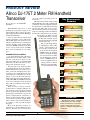
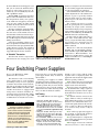
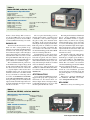
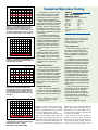
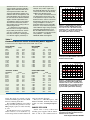
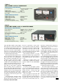
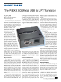
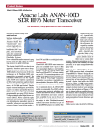
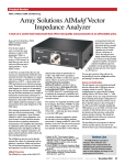
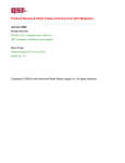
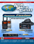
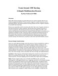
Product Review and Short Takes from QST Magazine August 2009 Product Reviews: Alinco DJ-175T 2 meter FM handheld transceiver Four switching power supplies Short Takes: The PIEXX SO2Rxlat USB to LPT Translator Copyright © 2009 by the American Radio Relay League Inc. All rights reserved. product review Alinco DJ-175T 2 Meter FM Handheld Key Measurements Transceiver Summary Reviewed by Steve Ford, WB8IMY QST Editor With handheld transceivers, as with anything else, you get what you pay for. So what would $99 buy you these days? Perhaps a stripped down rig with an RF output measured in milliwatts? In the case of the Alinco DJ-175T, which retails for around $99, you get a radio with a full 5 W RF output, not to mention 39-tone CTCSS (Continuous Tone Coded Squelch System), digitally coded squelch (DCS), tone bursts, DTMF encoding and extended receive coverage from 136-173.995 MHz. That’s pretty remarkable for a two-digit price. Standard Features, and More I’ve already mentioned the 5 W output, but the DJ-175T can ratchet down to 2 W and even 1⁄2 W when you want to really prolong the battery life. As with many FM transceivers, the DJ-175T offers an automatic power off function as well. The DJ-175T’s tone functions make it downright musical. It has the ability to transmit CTCSS tones for repeater access, and it can decode and display those tones, too. There is also a DCS function for those systems that use it. And while we’re on the subject of tones, the DJ-175T offers the ability to transmit four separate burst tones: 1750, 2100, 1000 and 1450 Hz. Tone-burst access isn’t commonly used in the United States, but it is in Europe and is handy to have just in case. When it comes to memory channels, the DJ-175T has a whopping 200, plus one call channel slot. You can tag the DJ-175T memory channels with alphanumeric labels that will appear on the LCD to jog your own memory. Coupled with the convenience of memory is the DJ-175T’s ability to rapidly scan the memory channels, stopping briefly when a signal is detected, then moving on, or coming to a full stop until the signal disappears. Most of the DJ-175T’s features are standard fare in the handheld transceiver universe, but there are at least two that are not as common, especially in low cost transceivers. The first is the DJ-175T’s charger stand. Most handhelds come with a standard wall wart battery charger. You plug the wall wart into the nearest ac outlet and insert its plug into the radio. That’s fine as far as it goes, but it means that you have to leave the radio lying on a countertop or wherever. Thanks to the DJ-175T’s charger stand, you can charge this rig like a pro. When it is time to replenish the battery, you drop the DJ-175T vertically into its elegant stand, keeping it upright and out of the way. The second unique feature is something the Alinco folks call the “refresh function.” It theoretically extends the life of the nickel-metal hydride (NiMH) battery by allowing you to occasionally discharge it to a low level, thus avoiding the dreaded battery “memory effect.” NiMH batteries are not as susceptible to this annoying problem as NiCds, but they are still vulnerable. See the informative article Mark J. Wilson, K1RO From August 2009 QST © ARRL 0.18 SINAD 0.25 0.1 Receiver Sensitivity (12dB SINAD, µV) I3 Rx 60 83@10 MHz 90 Receiver 3rd-Order Dynamic Range (dB) I3 70@20 kHz 70 Rx 40 Receiver 3rd-Order Dynamic Range (dB) ChRej 50 70 IF 60 Img 60 Snd 100 T-R 250 pr039 90 Adjacent Channel Rejection (dB) 95 IF Rejection (dB) 81 Image Rejection (dB) 410 Audio Output (mW) 155 110 110 800 50 Tx-Rx Turnaround Time (ms) Bottom Line The Alinco DJ-175T is a compact handheld with more than enough power (and features) to satisfy the needs of most hams. At around $99, it’s a standout among low-cost handhelds. Product Review Editor [email protected] by Isidor Buchmann at www.buchmann. ca/Article10-Page1.asp. If you need more battery capacity, you can get the optional EBP-71 1200 mAh lithium-ion pack. That requires a different charger, though. Programming Software Alinco offers a free Windows programming application for use with the DJ-175T. You can download it from the Alinco Web site at www.alinco.com/main07-05.html. To use the software you’ll need Alinco’s ERW-7 USB cable, which retails for about $50. The ERW-7 configures as a “virtual serial (COM) port” when you plug it into your PC. However, you have no way of knowing which COM port number has been assigned to the ERW-7 unless you take the added step of opening Windows Device Manager, which you’ll find under the SYSTEM icon in Windows Control Panel. In my station computer, the ERW-7 was assigned as COM 9; your computer will be different. A serial port cable is also available if USB won’t work for you. With this vital information in hand, you start the application and select the correct COM port under the TOOLS menu. You then connect the DJ-175T to the cable and switch it on. From there it is a simple step to read the information that’s already in the rig, modify it and then write it back to the radio (Figure 1). Of course, you don’t need software to manage the DJ-175T, but the program makes the task much easier. You can sit down at your computer and fill the DJ-175T’s memories in a single session. You can even set the volume and squelch levels, among other things. If you are part of a group, or have multiple radios, you can easily set them all up to have the same settings. In the ARRL Lab The results of ARRL Laboratory testing are shown in Table 1. Test Engineer Bob Allison, WB1GCM, noted that receive audio began to distort at high levels. Lab tests confirmed that the 10% THD threshold is crossed at volume level 16. About 35% THD was measured at maximum volume. During typical use in the field, however, I rarely exceeded volume level 10. Overall, the RF output was cleanest at high power. At lower output levels, harmonics crept upward, but were still within limits. It was interesting to note that Alinco designed the DJ-175T with the first IF at 21.7 MHz. This resulted in very good IF rejection. Table 1 Alinco DJ-175T, serial number M000995 Manufacturer’s Specifications Measured in ARRL Lab Frequency Coverage: Receive, 136- 173.995 MHz; transmit, 144-147.995 MHz. Receive and transmit, as specified. Modes of operation: FM. As specified. Power requirements: 7.2/7.4 V dc (battery only); receive, 250 mA (max volume), 70 mA (standby) 30 mA (battery save on), transmit, 1.6 A (high power).† Receive, (max volume, no signal) 190 mA; 76 mA (standby); 36 mA (battery save). Transmit, 1.2, 0.73, 0.40 A (hi, med, lo). Receiver Receiver Dynamic Testing FM sensitivity: 12 dB SINAD, 0.2 µV. For 12 dB SINAD, 0.18 µV. FM two-tone, third-order IMD dynamic range: Not specified. 20 kHz offset: 70 dB; 10 MHz offset: 83 dB. FM two-tone, second-order IMD dynamic range: 146 MHz, 81 dB. Not specified. Adjacent-channel rejection: Not specified. 20 kHz offset: 70 dB. Spurious response: Not specified. IF rejection, 95 dB; image rejection, 81 dB. Squelch sensitivity: Not specified. At threshold, 0.11 µV. Audio output: 400 mW at 10% THD into 8 Ω. 410 mW at 10% THD into 8 Ω. Transmitter Transmitter Dynamic Testing Power output: 5.0 W high, 2.0 W med, 0.5 low. 5.3, 2.3, 0.6 W (hi, med, lo) Spurious signal and harmonic suppression: 60 dB or less. 60 dBc; meets FCC requirements. Transmit-receive turnaround time (PTT release to 50% of full audio output): Not specified. Squelch on, S9 signal, 155 ms. Receive-transmit turnaround time (“tx delay”): Not specified. 120 ms. Size (height, width, depth): 4.2 × 2.3 × 1.4 inches; weight, 8.7 ounces. Price: DJ-175T, $100; EME-12 headset with VOX, $90; ERW-7 USB cable, $50. †EBP-72 battery pack (7.2 V, 700 mAh NiMH) and EDC-165T drop-in trickle charger supplied. Available options: Replacement EBP-72, $46. EBP-71 battery pack (7.2 V, 1200 mAh Li-ion), $49; EDC-164T drop-in charger for Li-Ion battery, $60. vention®! When you pack 15,000+ people into a relatively small area — with most of them operating on 2 meters — communication can be a challenge to put it mildly. Alinco offers the EME-12 VOX (voice- operated switch) headset for the DJ-175T, which is a great accessory to have when you need to keep your hands free. The lightweight headset, shown in Figure 2, covers one ear and extends a thin microphone to Figure 1 — Using the free Alinco software, you can program the DJ175T memories and other settings from any Windows PC. An optional cable is required. Baptism of Fire Not long after I received the DJ-175T, I subjected it to one of the most difficult environments available — the 2009 Dayton HamFrom August 2009 QST © ARRL the front. With the DJ-175T clipped to your belt, you can activate the VOX function to key the rig at the sound of your voice. Alternatively, you can manually key the radio with a pushbutton switch. With the EME-12 attached to the handheld, I roamed the Hamvention with ease. The microphone has a fairly “close” pattern, so the VOX wasn’t tripped by extraneous noise. Of course, I had to be a little careful to disable the headset when I was involved in a face-to-face conversation. The DJ-175T held up against the Hamvention RF onslaught remarkably well. Yes, there was a certain amount of receiver desensitization at times, but it wasn’t objectionable. The headset audio was clear and at the 5 W RF output level I had no difficulty making myself heard. Using the programming software, I was able to set up the DJ-175T memories before I even left Connecticut. I programmed all the popular Dayton repeaters and configured the display to indicate their call signs as I stepped through the memory channels. A “Valuable” Transceiver The Alinco DJ-175T is a compact handheld with more than enough power (and Figure 2 — The EME-12 headset includes a VOX function for hands-free operation. features) to satisfy the needs of most hams. It isn’t an extremely rugged radio, but I found it to be more than durable for normal use. Some will find that the audio volume and squelch adjustments are a bit cumbersome. You have to press a special key and then rotate the knob at the top. But considering the low price, this seems to be a minor nuisance at best. The standard-issue battery provides plenty of operating time and, as mentioned previously, the charger stand is extremely convenient. The display is large enough to be easily readable and all controls were useable without too much difficulty, the VOLUME and SQUELCH functions notwithstanding. In other words, the Alinco DJ-175T is a good “value” in the traditional sense. That is to say, you get much more than you might expect for the price. Among the low-cost handheld transceivers, the DJ-175T is a definite stand-out. Manufacturer: Alinco Inc, Yodoyabashi Dai-Bldg 13F, 4-4-9 Koraibashi, Chuo-ku, Osaka 541-0043, Japan; www.alinco.com. US distributor: Ham Distributors, 1775 North Loop, 336 East, Suite 8, Conroe, TX 77301; tel 936-649-1497; e-mail USrep@ hamdistributors.com. Four Switching Power Supplies Reviewed by Mark Wilson, K1RO QST Product Review Editor This month we look at four switching power supplies that are good candidates for running a variety of 13.8 V equipment as found in most modern amateur stations. The units are the Daiwa SS-505, Jetstream JTPS45, MFJ-4245MV and Samlex SEC1235M. All of them are equipped with analog meters, and their continuous current ratings range from 30 to 50 A. That’s more than enough power for a typical HF or VHF transceiver and station accessories. Past reviews have covered other switching power supply models, many of which are still available.1-4 Switching power supplies are smaller and lighter than linear supplies with comparable ratings. The heaviest in this group is less than 9 pounds. They are more efficient and generate less heat, typically requiring small internal heat sinks and using small fans to circulate air inside the cabinets. Lab Testing The ARRL Lab ran each of the supplies 1J. Bottom Line All of these supplies effortlessly deliver high current for your transceiver and accessories and include voltage and current metering and protection circuits. Although all of them have low conducted emissions (which can cause interference to your receiver) in the amateur bands, there are some significant differences at low frequencies. From August 2009 QST © ARRL Bottiglieri, AA1GW, “QST Compares: Switching Power Supplies,” Product Review, QST, Jan 2000, pp 70-73. Includes Astron SS-30M, ICOM PS-85, Kenwood PS-40, MFJ-4225MV, Samlex SEC-1223 and Yaesu FP-1023 QST Product reviews are available on the Web at www.arrl.org/members-only/ prodrev/. 2J. Bottiglieri, AA1GW, “Switching Power Supplies Revisited,” Product Review, QST, Sep 2000, pp 76-79. Includes Alinco DM-330MV and Diamond GZV4000. 3S. Ford, WB8IMY, “ICOM PS-125 Power Supply,” Product Review, QST, Sep 2002, p 62. 4M. Wilson, K1RO, “More Switching Power Supplies,” Product Review, QST, Jul 2006, pp 58-61. Includes Daiwa SS-330W, Kenwood KPS-15, MFJ-4125 and Ten-Tec 963. through a series of tests, with the results reported in the accompanying tables and graphs. The tests measure the supplies under different operating conditions: The output voltage was measured with no load, 21 A and 35 A loads (for the three supplies rated at more than 30 A). AC line voltage was adjusted to measure the minimum line voltage required to maintain proper regulation of the dc output. In the tables this is shown as Low line drop out voltage. A dynamic load was connected to the supply, similar to what you would expect during SSB or CW operation, as you switch between receive and transmit. In this case, a test fixture rapidly alternates the load between 1.1 and 21 A. The test result appears as dc variation during dynamic testing in the tables. An oscilloscope plot shows ripple on the dc output, as well as high frequency switching spikes while under load. A spectrum analyzer ac-coupled to the power supply output shows noise generated from 1.5 to 100 MHz. Each supply was tested for conducted emissions (noise that a device introduces Table 2 Daiwa SS-505, serial no. 1708 Manufacturer’s Specifications Power requirement: 90-123 V ac. Output voltage: 5-15 V dc. Output current (continuous): 50 A. Size (HWD): 4.4×8.5×11.1 inches; weight, 8.4 pounds. Price: $370 ARRL Lab Measurements Output voltage, no load: Output voltage, 21 A load: Output voltage, 35 A load: Voltage range: Low line drop out voltage: Dc variation during dynamic testing: 13.71 V dc (set by Test Engineer). 13.53 V dc. 13.51 V dc. 4.48-14.42 V dc. 69 V ac. ≈200 mV. into the ac house wiring). This is a new test, one that the ARRL Lab was not equipped to perform for past reviews. See the sidebar “Conducted Emissions Testing” for details. Daiwa SS-505 The Daiwa SS-505 is housed in a sturdy metal case with a carrying handle on top, and there are removable soft rubber bumpers around the front and back edges. Rated for 50 A continuous output, it offers the highest current rating in this group. Output voltage is adjustable from about 4.5 to 14.4 V via the front-panel VADJ knob. The wide voltage adjustment range and carrying handle make it a good candidate for a workbench supply. The non illuminated front panel meter is switchable between output voltage (0-30 V) and current (0-60 A). The front panel also offers two low-current dc connections — a cigarette lighter socket rated for 10 A maximum and two sets of spring-loaded terminals rated for 6 A each. These would be very convenient for connecting station accessories. A red POWER switch and LEDs for AC LINE and PROTECTOR complete the front panel. The protection circuitry limits output current if internal temperatures rise too high and disables the supply if output current exceeds 56 A. The rear panel has binding posts for the high current output, a ground post and a detachable ac line cord. The exceptionally quiet cooling fan is mounted inside the cabinet, on the rear panel. It speeds up under higher loads and gets just a bit louder. Both side panels are ventilated over much of their area, providing good airflow. The case remains cool to the touch, even after extended transmitting periods with a 100 W transceiver drawing about 20 A. Documentation is a color A4 size sheet that includes specifications, drawings of the front and rear panels, and some cautions. No warranty information or schematic is included, but information about a 1 year warranty and return/repair details are included on the US distributor’s Web site. Manufacturer: NCG Company (US distributor), 15036 Sierra Bonita Ln, Chino, CA 91710; tel 909-393-6133; www.comet antenna.com. Jetstream JTPS45 At 8.8 pounds, the JTPS45 the heaviest supply in this group and is packaged in a solid metal case. It’s rated for 40 A continuous output current, and output voltage is adjustable from about 7.5 to 14.5 V with the front-panel DC ADJUST control. The front panel includes two illuminated meters — 0-16 V and 0-60 A. As does the Daiwa, the JTPS45 includes a cigarette lighter socket (7 A) and two sets of spring loaded terminals (also 7 A) for connecting accessories. Two binding posts, also on the front panel, handle the high current output. The rear-panel power cord is removable. An adjacent switch selects between 120 V and 240 V ac line voltage. Overcurrent protection kicks in at 50 A. The internal cooling fan, which always runs, is quiet. As temperature builds, the fan kicks up to a higher speed, and there’s a front panel LED for FAN LOW/HIGH . Vents on the side and rear panel offer good airflow. The case remains cool touch after extended transmitting periods with a 100 W transceiver drawing about 20 A. Documentation is an A4 size sheet folded in half. It covers installation, operation and specifications and includes front and rear panel diagrams. A 1 year warranty is provided. Manufacturer: Jetstream, 100 Hancock Ave, Hamilton, OH 45001; tel 513-8681353; www.jetstream-usa.com. MFJ-4245MV MFJ offers a variety of switching power Table 3 Jetstream JTPS45, serial no. 0803706 Manufacturer’s Specifications Power requirement: 85-135 V ac 47-62 Hz or 170-260 V ac 47-63 Hz. Output voltage: 9-15 V dc. Output current (continuous): 40 A. Size (HWD): 4.5×8.9×8.5 inches; weight, 8.8 pounds. Price: $150 ARRL Lab Measurements Output voltage, no load: Output voltage, 21 A load: Output voltage, 35 A load: Voltage range: Low line drop out voltage: Dc variation during dynamic testing: 13.61 V dc (detent). 13.53 V dc. 13.43 V dc. 7.45-14.50 V dc. 81 V ac. ≈165 mV. From August 2009 QST © ARRL QS0908-Prodrev03 0.2 Conducted Emissions Testing 0.15 0.1 0.05 0 -0.05 -0.1 -0.15 -0.2 0 0.005 0.01 0.015 0.02 0.025 0.03 0.035 0.04 Figure 3 — An oscilloscope trace of the dc output of the Daiwa SS-505 under load. The vertical scale is 50 mV/div and the horizontal scale is 5 ms/div. The level of the dc ripple is approximately 35 mV p-p. There are no discernible spikes due to switching. QS0908-prodrev04 0 -10 -20 -30 -40 -50 -60 -70 -80 0 10 20 30 40 50 60 70 80 90 100 Figure 4 — Spectral plot (0-100 MHz) of the output of the Daiwa SS-505 under load. Reference level is 0 dBm. QS0908-Prodrev05 0.2 0.15 0.1 0.05 0 -0.05 -0.1 -0.15 -0.2 0 0.005 0.01 0.015 0.02 0.025 0.03 0.035 0.04 Figure 5 — Oscilloscope trace of the dc output of the Jetstream JTPS45 under load. The vertical scale is 50 mV/div and the horizontal scale is 5 ms/div. The level of the dc ripple is approximately 10 mV p-p, with spikes due to switching of about 80 mV p-p. As described in a recent review of dc to ac power inverters, the ARRL Lab now has the ability to perform conducted emissions testing.5 We’ll briefly recap that information here. Some electronic devices, including switching power supplies, intentionally generate RF as part of their normal operation. This RF is not intended to be radiated as it would be by a transmitter. Under Part 15 of the FCC rules, such devices are defined as unintentional emitters. For Amateur Radio applications, a concern is RF noise generated by the switching regulators. These power supplies are designed and built with shielding and other EMI reduction techniques to suppress noise that could be heard in a station receiver — some with greater success than others. As with all Part 15 devices, unintentional emitters must not cause harmful interference to a licensed radio service such as Amateur Radio. In addition, Part 15 rules further establish absolute limits for two types of emissions from unintentional emitters. Conducted Emissions These emissions are conducted onto the house wiring and power lines via the device power cord. Part 15 provides absolute limits for conducted emissions from 150 kHz to 30 MHz. Conducted emissions are the primary problem below 30 MHz because ac power wiring provides a physically large “antenna” at HF and lower frequencies. Radiated Emissions These are emissions radiated by the device itself. The absolute limits in this case are specified at 30 MHz and higher. Power lines are relatively inef5H. QS0908-prodrev06 0 Robins, W1HSR, “DC to AC Power Inverters,” Product Review, QST, Apr 2009, pp 44-49. Table 6 Part 15 Conducted Emission Limits Quasi-peak detection measurements Frequency Limit (MHz) (dBµV) 0.15 - 0.5 66 to 56* 0.5 - 5.0 56 5.0 - 30.0 60 >30.0 None *Decreases with the logarithm of the frequency. ficient transmission lines at VHF and higher frequencies, so radiated emissions are the primary problem at those frequencies. Power Supply Tests FCC Part 15, Section 15.107, sets the limits for conducted emissions. See Table 6. Limits are expressed in dBµV, or dB relative to a microvolt. In this case, 1000 µV of signal equals +60 dBµV. The ARRL Lab uses a line impedance stabilization network (LISN) and a calibrated Rohde & Schwarz ESH-3 EMC receiver to measure conducted emissions. The device under test is plugged into the LISN, which separates the unwanted RF from the desired 60 Hz ac power. The conducted emissions are then measured by the special Rohde & Schwarz receiver using CISPR quasi-peak detection as specified in FCC Part 15. (This technique uses AM and a 9 kHz bandwidth and is designed to assess the effect of interference of a received signal to the human ear.) Table 7 shows the levels measured in the ARRL Lab at 137 and 505 kHz; the four highest levels outside the amateur bands; and the six highest levels inside the amateur bands. Tests were performed with 1 A and 20 A loads, typical of current levels required in receive and transmit. All of the supplies tested were -10 -20 -30 -40 -50 -60 -70 -80 0 10 20 30 40 50 60 70 80 90 100 Figure 6 — Spectral plot (0-100 MHz) of the output of the Jetstream JTPS45 under load. Reference level is 0 dBm. From August 2009 QST © ARRL supplies. At 40 A continuous output, the 4245MV is near the top of the line. Output voltage is adjustable from the front panel over a range of about 7.6 to 14.6 V. The two illuminated front panel meters display current (0-60 A) and voltage (016 V). Low current outputs include a cigarette lighter socket on the front panel (7 A) and two sets of spring terminals on the rear panel (5 A). The high current output is from binding posts on the front panel. The rear panel ac power cord is removable, and a rear panel switch selects 120 or 240 V ac operation. Protection circuits for overvoltage and overcurrent are included. The cooling fan, which is mounted to the inside rear panel, draws air through holes in the cabinet sides. Fan speed varies with output voltage setting. It runs all the time and is noticeably loud at 13.8 V well below the Part 15 levels on the amateur bands. The Daiwa and MFJ supplies were above the limits at several frequencies below 1 MHz. The Jetstream and Samlex supplies were under the limits at all frequencies, and overall the Samlex was the quietest of the units tested. The Samlex and MFJ supplies had the required FCC Part 15 compliance notices on the cabinet. The other two units did not, nor did they mention Part 15 testing in the accompanying literature. It is important to note that Part 15 limits are not low enough to eliminate the possibility of interference. Interference from a supply that is near the limits may show up as a buzzing noise or as discrete signals, particularly at the lower end of the spectrum. For example, at my station signals from the Daiwa SS-505 were very strong at LF and several were weak but clearly audible in the 160 meter band. The severity of the interference can also depend upon other factors such as the placement of power cords and distance from the antenna. I observed that lifting the ground on the ac cord (using an adapter for an older ungrounded outlet) caused a noticeable increase in noise while listening in the 150 to 500 kHz range. Using a properly grounded outlet helped in this case. See the ARRL RFI Book for information on techniques to help with interference problems. — Bob Allison, WB1GCM, ARRL Test Engineer QS0908-Prodrev07 0.2 0.15 0.1 0.05 0 -0.05 -0.1 -0.15 -0.2 0 Figure 7 — Oscilloscope trace of the dc output of the MFJ-4245MV under load. The vertical scale is 50 mV/div and the horizontal scale is 5 ms/div. The level of the dc ripple is <10 mV p-p. There are no discernible spikes due to switching. QS0908-prodrev08 0 Table 7 Conducted Emission Levels of Switching Power Supplies Conducted emissions in dBµV measured in the ARRL Lab. See text. Daiwa SS-505 Frequency MHz 0.137 0.180 0.290 0.505 0.595 0.650 Load 1 A 58.9 90.4 81.0 51.3 60.8 53.9 1.840 1.901 1.959 3.509 3.619 3.922 34.3 30.9 34.1 17.1 20.1 20.4 MFJ-4245MV 0.005 0.01 0.015 0.02 0.025 0.03 0.035 0.04 -10 -20 -30 -40 -50 20 A 82.6 95.6 62.2 61.5 62.7 67.9 Frequency MHz 0.137 0.174 0.245 0.505 0.525 0.595 Load 1 A 51.0 78.1 77.2 15.5 62.0 59.7 20 A 51.0 83.0 74.2 20.4 58.6 65.0 45.1 36.3 37.8 23.1 24.1 24.8 1.820 1.857 1.928 3.504 3.539 3.820 23.9 26.0 25.8 22.9 27.4 28.4 36.2 39.1 38.9 38.9 41.1 42.9 -60 -70 -80 0 10 20 30 40 50 60 70 80 90 100 Figure 8 — Spectral plot (0-100 MHz) of the output of the MFJ-4245MV under load. Reference level is 0 dBm. QS0908-Prodrev09 0.2 0.15 0.1 0.05 Jetstream JTPS45 Frequency MHz 0.137 0.161 0.227 0.505 0.518 0.595 Load 1 A 10.5 49.4 46.4 10.5 38.8 36.4 1.815 1.882 1.914 3.502 3.535 3.895 29.0 26.4 22.2 26.5 23.4 25.5 0 Samlex SEC-1235M -0.05 20 A 12.1 62.8 49.8 17.1 50.6 44.1 Frequency MHz 0.137 0.169 0.237 0.505 0.540 0.572 Load 1 A 22.7 47.1 28.5 17.0 25.9 36.7 20 A 22.7 49.0 28.5 13.0 32.6 31.7 46.1 46.9 40.7 36.0 37.5 35.0 1.814 1.847 1.913 3.553 3.622 3.885 24.0 27.7 29.7 20.5 20.7 20.5 42.2 38.0 39.3 35.5 36.1 38.0 -0.1 -0.15 -0.2 0 0.005 0.01 0.015 0.02 0.025 0.03 0.035 0.04 Figure 9 — Oscilloscope trace of the dc output of the Samlex SEC-1235M under load. The vertical scale is 50 mV/div and the horizontal scale is 5 ms/div. The level of the dc ripple is approximately 15 mV p-p with small spikes due to switching. 0 QS0908-prodrev10 -10 output. The supply does remain cool after extended transmitting periods with a 100 W transceiver drawing about 20 A. The first MFJ-4245MV we tested failed during extended testing with the 21 A load. MFJ promptly replaced it under warranty (1 year). Documentation is an 8.5 × 11 inch sheet folded in half. It covers installation, operation and specifications and includes front panel and schematic diagrams. Manufacturer: MFJ Enterprises, 300 Industrial Park Rd, Starkville, MS 39759; tel 662-323-5869; www.mfjenterprises. com. Samlex SEC-1235M Samlex offers a variety of linear and switching power supplies with the Samlex name as well as some manufactured for -20 -30 -40 -50 -60 -70 -80 0 10 20 30 40 50 60 70 80 90 100 Figure 10 — Spectral plot (0-100 MHz) of the output of the SEC-1235M under load. Reference level is 0 dBm. From August 2009 QST © ARRL Table 4 MFJ 4245MV, serial no. L4000006845 Manufacturer’s Specifications Power requirement: 85 to 135 V ac 47-62 Hz or 170 to 260 V ac 47-63 Hz Output voltage: 9-16 V dc. Output current (continuous): 40 A. Size (HWD): 4.7×7.5×9.0 inches; weight, 5.5 pounds. Price: $185. ARRL Lab Measurements Output voltage, no load: Output voltage, 21 A load: Output voltage, 35 A load: Voltage range: Low line drop out voltage: Dc variation during dynamic testing: 13.63 V dc (detent). 13.54 V dc. 13.47 V dc 7.63 to 14.60 V dc 79 V ac. ≈150 mV. Table 5 Samlex SEC 1235M, serial no. 03435-7E01-00653 Manufacturer’s Specifications Power requirement: 100-130 V ac 60 Hz or 200-260 V ac 50 Hz. Output voltage: 13.8 V dc, internally adjustable 11.5-15.5 V dc. Output current (continuous): 30 A. Size (HWD): 2.5×7.3×8.4 inches; weight, 3.4 pounds. Price: $140. ARRL Lab Measurements Output voltage, no load: Output voltage, 21 A load: Voltage range: Low line drop out voltage: Dc variation during dynamic testing: 13.85 V dc. 13.71 V dc. 11.2 to 16.2 V dc. 86 V ac. ≈140 mV. o thers. The SEC-1235M is a compact supply that weighs only 3.4 pounds. It’s rated for 30 A continuous output. Output voltage is set to 13.8 at the factory but internally adjustable from 11.2 to 16.2 V. Current rating is reduced to 25 A at 16 V output. Line voltage is factory set to 120 V but can be changed to 240 V through internal settings. The front panel includes just two meters (0-15 V and 0-40 A) and a lighted power switch. The meters are not illuminated. The rear panel has a detachable power cord and the dc output connections. Unlike the other supplies in this group, the SEC1235M does not offer multiple low current outputs. Screw-down terminals on the rear panel provide the only dc output connections. The set screws require a small flat blade screwdriver and are accessible from the top of the cabinet. The manual cautions against inserting stranded wire into these terminals, as the set screws will spread the strands and may not make a good connection. A pair of terminals that can be crimped or soldered to your transceiver power cord are included A thermostatically controlled cooling fan is mounted inside the cabinet, on the bottom panel. The side panels are vented. From August 2009 QST © ARRL The fan is controlled by a sensor on the power transformer and runs only when the temperature exceeds 60° C. During normal operation the fan rarely comes on. The case remains cool to the touch, even after extended transmitting periods with a 100 W transceiver drawing about 20 A. The instruction manual is a 12 page booklet that includes setup, operation and safety information as well as specifications and troubleshooting tips. The warranty is 3 years. Manufacturer: Samlex America, 11017 Fawcett Rd, Coquitlam, BC V3K 6V2, Canada; tel 604-525-3836; www.samlex. com. Some Impressions In the Lab, all of the supplies could be set to 13.8 V output with no load. All of the supplies kept good regulation during the dynamic load test — all were in the 140200 mV range, typical of other switching supplies we’ve tested. All of the supplies reviewed here will maintain regulation over a wide range of ac line inputs. The Daiwa SS-505 maintained regulation all the way down to 69 V. This is not an issue for normal home station use, but may be a useful feature for emergencies, ARRL Field Day and other situations subject to line voltage fluctuation. In past reviews, we observed significant switching spikes and ripple on the output of several supplies. All of the supplies in this review exhibit good performance in this area (Figures 3, 5, 7 and 9). The spectrum analyzer plots (Figures 4, 6, 8 and 10) show the output spectrum under load, up to 100 MHz. The plots show the noise levels under a typical 100 W transmitter load, and the noise levels are lower with the 1 A load typical during receive. All of the supplies were relatively quiet in this test. We did notice some differences among them during conducted emissions testing. See the accompanying sidebar for details. Any of these supplies would make a good power source for your station. The Daiwa SS-505 has the highest current rating, but also costs twice as much as any other supply in this group and exhibited more conducted noise than the others. A lightweight, cool running switching supply can provide good performance in a compact package. Over the years, noise performance has improved and is no longer a concern for most amateur operation. short takes The PIEXX SO2Rxlat USB to LPT Translator Pete Smith, N4ZR 96 Willow Well Ln Kearneysville, WV 25430-5811 [email protected] gained quite a reputation for their broad line of computer-to-radio interfaces, antenna switchboxes and other products. To support the company’s MK2R+ multi-mode SO2R controller, using only a single USB cable to the computer, MicroHAM developed and began encouraging software developers to support the MicroHAM SO2R Protocol. For more than 20 years, the standard for automating an Amateur Radio station has been to use standard serial (COM) and parallel printer (LPT) ports. By manipulating the states of various lines on these ports, loggers and other software could activate PTT (Push To Talk), send CW, control two-radio controllers such as the TopTen DX Doubler, and automatically switch antennas. Alas, even as more and more radio amateurs were incorporating such devices in their stations, the computer manufacturers were moving away from hardware COM and LPT ports and settling on USB as their standard for connecting printers, scanners and other peripherals. Already, almost all new laptops and desktops only incorporate USB ports. This doesn’t pose many problems for those whose only interest is connecting a transceiver to a logging program because USB-toserial converters can do everything that’s needed, and can even be set up to do PTT and CW chores. But what about the LPT port, much used for SO2R (Single Operator Two Radio) contest operating and automatic antenna switching? This ingenious protocol uses simple serial commands to control peripheral devices and has quickly been adopted by most Windowsbased contest and general purpose logging software. Why a Translator? How the SO2Rxlat Works Hams quickly discovered that USB-toparallel adapters, while they existed, didn’t support the standard ways of using the LPT port to control antenna switches and SO2R controllers. Something different was needed. From stage right, enter Chris Sieg, WA3LDI, of PIEXX Company, already well-known in the ham community for a variety of handy gadgets using microcontrollers, particularly the TS-930 Microprocessor Board that gives new life to that excellent older transceiver by adding computer control and a lot of other features. From stage left, enter MicroHAM, which was working on the same problem from a different angle. This Slovak company and its US subsidiary, MicroHAM USA, have With the SO2R Protocol standard already in place, it only made sense for PIEXX to develop its hardware to interpret part of the MicroHAM command set, and translate it to the resulting parallel port signals. The SO2Rxlat does what its name implies — it receives the MicroHAM commands and translates them into their standard LPT port equivalent. For example, most SO2R controllers use LPT port pin 5 to switch between “mono” (both ears on one radio) and “stereo” (one radio in each ear). The MicroHAM protocol uses “FRS” to toggle between the two — the SO2Rxlat turns that into control voltage on Pin 5 of its built-in parallel port plug. Similarly, “AS1xx,” where xx is 0-9, applies power to the appropriate pins of the LPT port to match a standard band decoder, enabling automatic switching of up to 10 antennas. The SO2Rxlat board incorporates two virtual serial ports connected to your computer through a single USB port. The first port controls the LPT port. The second port can be used to control CW and PTT by utilizing the standard COM port RTS and DTR lines and is also available to perform general rigcontrol functions. It can be ordered either as a standard RS-232 port or as a CI-V ICOM-style communications port. Trying It Out All this is really a lot harder to describe than it is to get going. I tested the SO2Rxlat with N1MM Logger and a TopTen DX Doubler SO2R controller. PIEXX has provided detailed, step-by-step instructions for installing the drivers and testing the unit and it all went very smoothly. The unit is powered by the computer’s USB port, which simplifies cabling — essentially, I just connected it to the LPT port on the back of the DX Doubler with a standard 25-pin serial cable, plugged in the provided USB cable, started the logging program and I was in business. Antenna and radio switching all went smoothly, as did the routing of CW and PTT control to the appropriate radio. Models of the SO2Rxlat are available with or without a display (showing the state of the LPT port) and with or without a case. The display is useful for debugging, but in most cases will be unnecessary — the SO2Rxlat truly is plug-and-play. Clean and Flawless To sum up, the SO2Rxlat can help you extend the life of your existing station automation hardware. It doesn’t add any bells and whistles, but it operates flawlessly. So until that hot new SO2R controller can fit in the budget, the SO2Rxlat makes good sense. Manufacturer: PIEXX Company, 13 Main St, PO Box 123, Hillsboro, NH 03244; tel 603-464-5625; www.piexx.com. SO2Rxlat with case and display, $131 plus shipping; with case but without display, $85 plus shipping. From August 2009 QST © ARRL