1
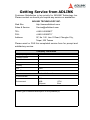
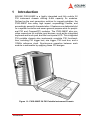
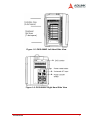
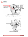
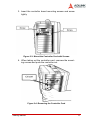
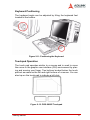
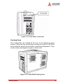
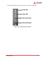
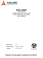
PXIS-2680P
8-Slot 3U PXI
Portable Instrument Chassis with
300W+300W AC Power Supply
User’s Manual
Manual Rev.
2.00
Revision Date:
January 28, 2005
Part No:
50-17019-100
Advance Technologies; Automate the World.
Copyright 2005 ADLINK TECHNOLOGY INC.
All Rights Reserved.
The information in this document is subject to change without prior
notice in order to improve reliability, design, and function and does
not represent a commitment on the part of the manufacturer.
In no event will the manufacturer be liable for direct, indirect, special, incidental, or consequential damages arising out of the use or
inability to use the product or documentation, even if advised of
the possibility of such damages.
This document contains proprietary information protected by copyright. All rights are reserved. No part of this manual may be reproduced by any mechanical, electronic, or other means in any form
without prior written permission of the manufacturer.
Trademarks
Product names mentioned herein are used for identification purposes only and may be trademarks and/or registered trademarks
of their respective companies.
Getting Service from ADLINK
Customer Satisfaction is top priority for ADLINK Technology Inc.
Please contact us should you require any service or assistance.
ADLINK TECHNOLOGY INC.
Web Site:
http://www.adlinktech.com
Sales & Service:
[email protected]
TEL:
+886-2-82265877
FAX:
+886-2-82265717
Address:
9F, No. 166, Jian Yi Road, Chungho City,
Taipei, 235 Taiwan
Please email or FAX this completed service form for prompt and
satisfactory service.
Company Information
Company/Organization
Contact Person
E-mail Address
Address
Country
TEL
FAX:
Web Site
Product Information
Product Model
Environment
OS:
M/B:
Chipset:
CPU:
Bios:
Please give a detailed description of the problem(s):
Table of Contents
Table of Contents..................................................................... i
List of Tables.......................................................................... iii
List of Figures ........................................................................ iv
1 Introduction ........................................................................ 1
1.1
1.2
1.3
Features............................................................................... 2
Specifications....................................................................... 3
Mechanical Drawing and Outline ......................................... 5
Mechanical Drawing ....................................................... 5
Outline ............................................................................ 6
2 Getting Started ................................................................... 9
2.1
2.2
2.3
2.4
2.5
2.6
Unpacking Checklist ............................................................ 9
System Configuration .......................................................... 9
System Controller Installation ......................................... 9
Peripheral Module Installation ...................................... 12
Power Supply Unit Replacement Procedures ............... 12
Operation Instructions........................................................ 15
How to Release Keyboard and Touch Pad ................... 15
How to Replace the Keyboard ...................................... 15
How to Setup the Keyboard .......................................... 16
Keyboard Positioning .................................................... 17
Touchpad Operation ..................................................... 17
LCD Display .................................................................. 18
DVD-ROM Drive ........................................................... 18
Cooling Fans ................................................................. 19
Software Installation .......................................................... 20
Powering Up the System ................................................... 20
System Monitoring ............................................................. 20
3 Backplane Overview ........................................................ 23
3.1
Specifications..................................................................... 23
System Controller Slot .................................................. 23
Star Trigger Slot ............................................................ 23
Peripheral Slots ............................................................ 23
Local Bus ...................................................................... 24
Table of Contents
i
3.2
3.3
Trigger Bus ................................................................... 24
System Reference Clock .............................................. 25
Mechanical Drawing........................................................... 26
Pin Assignment .................................................................. 27
System Controller ......................................................... 27
Star Trigger ................................................................... 29
General Peripheral ........................................................ 31
4 Troubleshooting and Maintenance ................................. 35
4.1
4.2
Troubleshooting ................................................................. 35
Installation Issues: ........................................................ 35
BIOS Beep Code: ......................................................... 35
System Fails to Power Up: ........................................... 35
No Display (LCD): ......................................................... 36
Keyboard Failure: ......................................................... 36
Touchpad Failure: ......................................................... 36
DVD-ROM Failure: ........................................................ 36
Maintenance ...................................................................... 37
PXIS-2680P .................................................................. 37
Cables ........................................................................... 37
LCD ............................................................................... 37
Power ............................................................................ 37
Keyboard ...................................................................... 37
Cleaning the LCD ......................................................... 38
Cleaning the Keyboard ................................................. 38
Important Safety Instructions............................................... 39
Warranty Policy ..................................................................... 41
ii
Table of Contents
List of Tables
Table
Table
Table
Table
Table
Table
Table
1-1:
3-1:
3-2:
3-3:
3-4:
3-5:
3-6:
Electrical Output ....................................................... 3
JP2 and JP3 PXI Reference Clock Control ............ 25
System Slot (Slot #1) P1 Pin Assignment .............. 27
System Slot (Slot #1) P2 Pin Assignment .............. 28
Star Trigger Slot (Slot #2) P1 Pin Assignment ....... 29
Star Trigger Slot (Slot #2) P2 Pin Assignment ....... 30
General Peripheral Slot (Slots #3 - #6) P1 Pin
Assignment ............................................................. 31
Table 3-7: General Peripheral Slot (Slots #3 - #6) P2 Pin
Assignment ............................................................. 32
Table 3-8: Signal Routing ........................................................ 33
Table 3-9: PXI_STAR Routing ................................................. 33
List of Tables
iii
List of Figures
Figure 1-1: PXIS-2680P 3U PXI Portable Instrument Chassis .... 1
Figure 1-2: PXIS-2680P Mechanical Drawing.............................. 5
Figure 1-3: PXIS-2680P Front Panel View................................... 6
Figure 1-4: PXIS-2680P Rear View ............................................. 6
Figure 1-5: PXIS-2680P Left Hand Side View ............................. 7
Figure 1-6: PXIS-2680P Right Hand Side View ........................... 7
Figure 2-1: System Controller Installation .................................. 10
Figure 2-2: Pull the Handle Up................................................... 10
Figure 2-3: Mount the Controller Card with Screws ................... 11
Figure 2-4: Removing the Controller Card ................................. 11
Figure 2-5: Redundant Power Supply (Front & Rear) ................ 12
Figure 2-6: Removing the Power Supply (A).............................. 13
Figure 2-7: Removing the Power Supply (B).............................. 14
Figure 2-8: Replacing the Power Supply.................................... 14
Figure 2-9: Releasing the Keyboard .......................................... 15
Figure 2-10: PXIS-2680P Keyboard............................................. 16
Figure 2-11: Positioning the Keyboard......................................... 17
Figure 2-12: PXIS-2680P Touchpad ............................................ 17
Figure 2-13: Lift the LCD Display Upward.................................... 18
Figure 2-14: PXIS-2680P DVD-ROM........................................... 19
Figure 2-15: PXIS-2680P Cooling Fans....................................... 19
Figure 2-16: System Monitoring Panel......................................... 21
Figure 3-1: PXI Local Bus and Star Trigger Routing.................. 24
Figure 3-2: cBX-3008L Front View Drawing............................... 26
Figure 3-3: cBX-3008L Rear View Drawing ............................... 26
iv
List of Figures
1
Introduction
ADLINK PXIS-2680P is a highly integrated and fully mobile 3U
PXI instrument chassis offering 8-slot capacity for modules.
Defined as the next generation solution for rugged portables, the
PXIS-2680P has many high impact, surpassingly flexible, and
exceedingly powerful characteristics. It features one dedicated slot
for a system controller and seven general purpose slots for peripheral PXI and CompactPCI modules. The PXIS-2680P also provides connectors for multiple input devices, such as the integrated
keyboard and touch pad, and the touch panel LCD. This integrated
PXI portable chassis also implements complete PXI functionalities, including PXI trigger bus, star trigger, PXI local bus, and a
10MHz reference clock. Synchronous operation between each
module is achievable by applying these PXI designs.
Figure 1-1: PXIS-2680P 3U PXI Portable Instrument Chassis
Introduction
1
The PXIS-2680P includes a 15” SVGA LCD touch screen—an
additional monitor is not necessary. No additional LCD, touch
panel, or keyboard wiring is required when using either the
ADLINK PXD-3710/3710F or the PXI-3800 system controller as all
necessary wiring has been integrated through the PXIS-2680P. A
built-in DVD combo drive is suitable for high speed recording or
backup of valuable data. A 300W+300W redundant power module
is included with the chassis, making the PXIS-2680P both ideal
and reliable for any critical application. The PXIS-2680P also has
two 8cm fans to provide an air flow rate of up to 79 CFM. Located
on the panel, there are several LEDs and an alarm speaker to
monitor any failure.
Users can develop custom Test and Measurement applications
directly on the PXIS-2680P, of which its environment is quite the
same as a standard PXI platform. By combining advanced
designs, the PXIS-2680P is able to supply a wide range of applications that run in an integrated portable and dependable chassis,
such as power industry, military, and telecommunication applications.
1.1 Features
2
X
Designed for portable instrument applications
X
Accepts both 3U PXI and CompactPCI modules
X
PICMG 2.0 CompactPCI specifications R3.0 compliant
X
PXI specification Rev.2.2 compliant
X
Provides a PXI trigger bus, 10MHz reference clock, star trigger, and PXI local bus
X
One system slot and 7 PXI/CompactPCI peripheral slots
X
High brightness 15” TFT LCD display, 1024×768 resolution
X
Multiple input devices including 108-key keyboard, touch
pad and touch panel
X
One built-in slim-type DVD combo drive
X
Dual hot swappable 300W ATX mini-redundant power supplies
Introduction
1.2 Specifications
Complies with PXI Rev.2.2 specifications and accepts modules
compliant with CompactPCI, PICMG 2.0 specifications
Electrical
X
AC Power Supply
Z
Dual 300W mini redundant, hot-swappable power supply, current sharing for all voltage
Z
Input voltage: 115 to 230VAC, auto selectable
Z
Input frequency: 47 to 63Hz ± 5%
Z
Output:
AC
+3.3V +5V
-5V +12V -12V +5Vsb
Max. Load
24A
0.8A
2.0A
Min. Load
0.3A 3.0A 0.1A 2.0A 0.1A
30A 0.5A
15A
0.1A
Table 1-1: Electrical Output
Note:
Combined power from +5V and +3.3V cannot exceed 150W.
Combined power from +5V, +3.3V and +12V cannot exceed
275W. Both -5V and +5Vsb are not used in the system.
Touch LCD Panel
X
15" TFT, 1024×768 resolution
X
250 nits, contrast 350:1, long live 50,000hrs backlight at
25°C
Input Devices
X
Keyboard: Mechanical-typed 108-key keyboard with touch
pad
X
Five keyboard types: Chinese, France, Germany, Russian,
USA
X
Touch screen: 15" resistive type, connected to COM2 RS232 interface, MTBF is 100,000hrs at 25°C
Drive Bay
X
One slim type drive bay with Combo drive 8X CD-R/RW: 8×
DVD-ROM, 24× CD-ROM
Introduction
3
Cooling
X
Two 8cm, 12VDC ball bearing fans, 41CFM air flow/each
Physical
X
Number of PXI/CompactPCI slots: 8 (1 controller, 7 peripherals)
X
Number of controller expansion slots: 3 (total 4-slot)
X
Dimensions: 400mm x 291mm x 230mm (W x H x D, without fan frame)
X
Net weight: 12kg without system controller and modules
Operating Environment
X
Ambient temperature: 0 to 50°C
X
Relative humidity: 20 to 90% @ 40°C, noncondensing
Storage Environment Temperature
X
Ambient temperature: -20 to 60°C
X
Relative humidity: 10 to 95% @ 40°C, noncondensing
Backplane
X
Backplane bare-board material: UL 94V-0 rated
X
Peripheral slots with star signals: from 3rd to the 8th slot
X
PXI trigger bus: all
X
PXI local bus: all
X
1 system slot on the left-hand side
X
7 peripheral slots, accept modules compliant with both PXI
and CompactPCI specifications
Shock and Vibration
X
Shock: 10Gpeak-to-peak, 11ms duration, non-operation
X
Random Vibration:
Z
Operating: 5 to 500Hz, 1.0GRMS, each axis
Z
Non-operating: 5 to 500Hz, 2.0GRMS, each axis
Safety and EMC/EMI Compliance
4
X
Safety: CE/LVD (EN60950)
X
EMC/EMI: CE, FCC Class A
Introduction
Reliability
X
MTBF:
Z
Backplane: 800,000hrs
Z
Power Supply: 100,000hrs @ full load
1.3 Mechanical Drawing and Outline
Mechanical Drawing
Figure 1-2: PXIS-2680P Mechanical Drawing
Introduction
5
Outline
Figure 1-3: PXIS-2680P Front Panel View
Figure 1-4: PXIS-2680P Rear View
6
Introduction
Figure 1-5: PXIS-2680P Left Hand Side View
Figure 1-6: PXIS-2680P Right Hand Side View
Introduction
7
8
Introduction
2
Getting Started
In this chapter, the unpacking procedure of the sub-system and
how to configure a portable PXI system is described.
2.1 Unpacking Checklist
Check the shipping carton for any damage. If the shipping carton
or its contents are damaged, please do not hesitate to notify the
dealer for a replacement. Retain this shipping carton and packing
material for inspection by the dealer. Check for the following items
in the package. If any items are missing, contact your dealer.
X
PXIS-2680P, 8-slot 3U PXI portable instrument chassis with
300W+300W AC power supply
X
This User’s Manual
X
ADLINK T&M All-in-One CD
X
Power cord (110V or 220V)
2.2 System Configuration
Before installing the system controller and peripherals on the
PXIS-2680P or doing any hardware installation, please make sure
that you completely understand the installation and compatibility of
any upgrade. Please be aware that electrostatic damage can
occur during handling of sensitive electronic equipments, proper
precaution needs to be taken.
System Controller Installation
The PXIS-2680P is a PXI chassis which is compatible with both
PXI and CompactPCI system controller. ADLINK’s PXD-3710/
3710F and PXI-3800 are the best choices for a system controller
with their dedicated designs. Please follow the steps listed below
to install and uninstall the system controller.
1. Smoothly slide the system controller into the system
controller slot. Make sure that the system controller is
aimed toward the rails. Never force the system controller
into the slot.
Getting Started
9
Figure 2-1: System Controller Installation
2. Push the handle until it clips in place. You will hear a
click sound when the handle has been pulled up.
Figure 2-2: Pull the Handle Up
10
Getting Started
3. Insert the controller board mounting screws and screw
tightly.
Figure 2-3: Mount the Controller Card with Screws
4. When taking out the controller card, unscrew the mounting screws and push the controller out.
Figure 2-4: Removing the Controller Card
Getting Started
11
Peripheral Module Installation
1. Smoothly slide the peripheral module into an available
peripheral slot. Make sure that the peripheral module is
aimed toward the rails. Never force the peripheral module into the slot.
2. Push the handle until it clips in place. You will hear a
click sound when the handle has been pulled up.
3. Insert the mounting screws and screw tightly.
4. When taking out the peripheral module, unscrew the
mounting screws and push the switch out.
Power Supply Unit Replacement Procedures
There are two 1U redundant power supplies with full range autosensing, auto selection, and 300W output. If one power supply has
a problem, the other will take over. An alarm will beep to remind
you to change the defective power supply.
Figure 2-5: Redundant Power Supply (Front & Rear)
12
Getting Started
Removing and Installing a Power Supply
1. Unscrew and remove the side panel.
Figure 2-6: Removing the Power Supply (A)
Getting Started
13
2. Pull out the power supply while pressing.
Figure 2-7: Removing the Power Supply (B)
3. To replace, push and slide in the new.
Figure 2-8: Replacing the Power Supply
14
Getting Started
2.3 Operation Instructions
How to Release Keyboard and Touch Pad
There are two release buttons located at the top-left and top-right
on the backside of the keyboard. After pressing in these two buttons, you can disengage the keyboard from PXIS-2680P. Two
mounting feet located beneath the keyboard and are inserted on
the portable for stability. The keyboard can now be lifted upward
and freely removed for usage.
Figure 2-9: Releasing the Keyboard
How to Replace the Keyboard
To replace the keyboard back into the PXIS-2680P, follow the
steps above in inverse. Note that the keyboard cable should be
put back its proper original lodging on the keyboard. Make sure
that all locking mechanisms are properly secured after the keyboard is pushed back. Never forcibly mount the keyboard to avoid
damaging the PXIS-2680P.
Getting Started
15
How to Setup the Keyboard
The keyboard cable is located on the top portion of the keyboard;
it is a coil cable with an RJ-45 connector at the end. The connector
needs to be attached to the portable (at the lower right hand corner) for operation.
Figure 2-10: PXIS-2680P Keyboard
16
Getting Started
Keyboard Positioning
The keyboard angle can be adjusted by tilting the keyboard feet
located at the bottom.
Figure 2-11: Positioning the Keyboard
Touchpad Operation
The touch pad operates similar to a mouse and is used to move
the cursor in the graphic user interface (GUI) environment by placing and moving your finger. Two buttons located below the touch
pad act as same as the left and right buttons of a mouse. You can
also tap on the touch pad to indicate a left click.
Figure 2-12: PXIS-2680P Touchpad
Getting Started
17
LCD Display
The LCD display has a fixed mechanism. You can pull up the pair
of feet at the bottom of the case to lift the LCD display upwards. To
relock the LCD display, simply enclose the keyboard and push the
feet back into its original position.
Before using touch panel functionality, you have to install the touch
panel driver according to your operating system. Please refer to
section 2.4 for details.
Figure 2-13: Lift the LCD Display Upward
DVD-ROM Drive
A DVD-ROM is located on the right side of the machine near the
top. Open the DVD-ROM drive door by pushing the eject button
located on the door of the drive. When the door is ejected, you can
pull the door out completely and clip in the DVD into the platter
securely face up; then push the door in completely. When the
DVD-ROM is accessed, the LED on the DVD door will light up
18
Getting Started
Figure 2-14: PXIS-2680P DVD-ROM
Cooling Fans
The cooling fans are located at the rear of the chassis for easy
access. There are two cooling fans running at a total of 79CFM to
ensure that the whole unit be within its working temperature. They
can be easily exchanged a newer or better one.
Figure 2-15: PXIS-2680P Cooling Fans
Getting Started
19
2.4 Software Installation
To enable the touch panel functionality, users need to first install
the driver into the system controller. To install the driver, please
insert the ADLINK T&M All-in-One CD shipped with PXIS-2680P
into the DVD-ROM. Drivers for different operating systems can be
found at:
X:\Driver Installation\PXI Platform\PXI chassis\PXIS2680P\Touch_Panel\Driver
Where X:\ is the DVD-ROM.
After installing the proper driver, the touch panel function can be
used.
2.5 Powering Up the System
Connect the supplied power cord to the socket on the right side of
the chassis. All supplied PSUs are universal and don’t require
input voltage settings. Inset a system module into the system slot.
The power connector is located on the right side of the machine
near the bottom. A three-pronged power plug is supplied. The
main power switch located next to the power connector. Its position is as follows: O = Off, I = On. To power on the system, first
turn on the PSUs and then power on the machine at the front of
the portable, labeled Power. To turn off the power, press the power
switch again after shutting down the OS.
2.6 System Monitoring
On the right side panel of the LCD, there are two LEDs and two
small buttons. The LED marked by a lamp represents the power
condition. This LED stays green when the system is on and is dark
when the system is off.
The LED marked by “T°!” indicates that the temperature inside the
PXIS-2680P is above 50°C. Once this occurs, this LED will light
red and the internal speaker will beep. When the temperature
drops back below 50°C, the alarm will automatically stop. Or,
pushing the alarm reset button will also stop the alarm. When one
of the fans fails, the alarm will again beep. Press the alarm reset
button can remove this alarm as well.
20
Getting Started
The LCD On/Off button turns the LCD on or off with each press.
Power LED
Temp. LED
Alarm reset button
LCD On/Off switch
Figure 2-16: System Monitoring Panel
Getting Started
21
22
Getting Started
3
Backplane Overview
The cBX-3008L backplane can accept both PXI compatible products and standard CompactPCI products. The signals on the P1
connector of the backplane meet CompactPCI specifications for
both peripheral and system modules.
PXI-specific signals are located on P2. Only reserved signals or
signals not used for the CompactPCI 64-bit specification are found
on PXI specific signals; therefore, all modules that meet CompactPCI 64-bit specification requirements are capable of operating in
the PXIS-2680P.
3.1 Specifications
System Controller Slot
The system controller slot is located at Slot 1 of the chassis as
defined by the PXI specification. It has three controller expansion
slots (four total), which are used for system controller modules that
are wider than one slot. As defined in the PXI specification, these
slots allow the controller to expand towards the left to prevent the
controller from using up peripheral slots.
Star Trigger Slot
The star trigger (ST) slot is located at slot 2. This slot has dedicated trigger lines between itself and slot 3 to 8, which are
intended for modules with ST functionality to provide individual
triggers to the peripherals.
Peripheral Slots
There are 7 peripheral slots including the star trigger controller
slot.
Backplane Overview
23
Figure 3-1: PXI Local Bus and Star Trigger Routing
Local Bus
The PXI backplane local bus of the cBX-3008L is a daisy-chained
bus that connects each peripheral slot with its adjacent peripheral
slots at the left and right. Each local bus is 13 lines wide and can
pass analog or digital signals between modules or provide a highspeed side-band communication path that does not affect the PXI
bus bandwidth. In accordance with the PXI specification, local bus
connections are between all slots except slots 1 and 2.
Trigger Bus
The PXIS-2680P implements a dedicated PXI trigger bus with 8
lines. Users can use these trigger lines to synchronize the operation of several different PXI peripheral modules, or use one module to control carefully timed sequences of operations performed
on other modules in the system. Modules can pass triggers to one
another through trigger bus, allowing precisely timed responses to
24
Backplane Overview
asynchronous external events the system is monitoring or controlling.
System Reference Clock
The PXIS-2680P supplies the PXI 10MHz system clock signal
(PXI_CLK10) independently to every peripheral slot. An independent buffer (having a source impedance matched to the backplane
and a skew of less than 1ns between slots) drives the clock signal
to each peripheral slot. Users can use this common reference
clock signal to synchronize multiple modules in a measurement or
control system or drive PXI_CLK10 from an external source
through the PXI_CLK10_IN pin on the P2 connector of the star
trigger slot. Users can select the internal or external clock by setting the jumper JP2 and JP3 in the back of the backplane.
JP2 JP3
Pin 1-2
Description
Open JP2
Short JP3
External clock through the
PXI_CLK10_IN on star trigger slot
Short JP2
Open JP3 Internal 10MHz system clock PXI_CLK10
(default)
Table 3-1: JP2 and JP3 PXI Reference Clock Control
Backplane Overview
25
3.2 Mechanical Drawing
The following figures show the two parts of the backplanes and
mechanical drawing.
Figure 3-2: cBX-3008L Front View Drawing
Figure 3-3: cBX-3008L Rear View Drawing
26
Backplane Overview
3.3 Pin Assignment
System Controller
Pin
Z
A
B
C
D
25
24
E
F
GND
+5V
REQ64#
ENUM#
GND
AD[1]
+5V
V(I/O)
+3.3V
+5V
GND
AD[0]
ACK64#
GND
23
GND
+3.3V
AD[4]
22
GND
AD[7]
GND
AD[3]
+5V
AD[2]
GND
+3.3V
AD[6]
AD[5]
GND
21
GND
+3.3V
AD[9]
AD[8]
GND
20
GND
AD[12]
GND
V(I/O)
AD[11]
19
GND
+3.3V
AD[15]
AD[14]
GND
18
GND
SERR#
GND
+3.3V
PAR
17
GND
+3.3V
16
GND
DEVSEL#
GND
15
GND
+3.3V
FRAME#
IPMB_SCL IPMB_SDA
12-14
C/BE[0]# GND
AD[10]
GND
AD[13]
GND
C/BE[1]# GND
GND
PERR#
GND
V(I/O)
STOP#
LOCK#
GND
IRDY#
GND
TRDY#
GND
Key
11
GND
AD[18]
AD[17]
AD[16]
GND
10
GND
AD[21]
GND
+3.3V
AD[20]
C/BE[2]# GND
AD[19]
GND
9
GND
C/BE[3]#
GND
AD[23]
GND
AD[22]
GND
8
GND
AD[26]
GND
V(I/O)
AD[25]
AD[24]
GND
7
GND
AD[30]
AD[29]
AD[28]
GND
AD[27]
GND
6
GND
REQ# (1)
GND
+3.3V
CLK (1)
AD[31]
GND
5
GND BRSVP1A5 BRSVP1B5
4
GND IPMB_PWR
3
GND
2
GND
1
GND
PCIRST#
GND
GND
V(I/O)
INTP
GNT# (1) GND
INTA# (1)
INTB# (1)
INTC# (1)
+5V
TCK
+5V
TMS
TDO
TDI
GND
+5V
-12V
TRST#
+12V
+5V
GND
INTS
GND
INTD# (1) GND
Table 3-2: System Slot (Slot #1) P1 Pin Assignment
Backplane Overview
27
Pin
Z
A
B
C
D
E
F
22 GND PXI_BRSVA22 PXI_BRSVB22 PXI_BRSVC22 PXI_BRSVD22 PXI_BRSVE22 GND
21 GND
CLK6
GND
NC
NC
NC
GND
20 GND
CLK5
GND
NC
GND
NC
GND
19 GND
GND
GND
SMBDATA
SMBCLK
SMBALERT-
GND
18 GND
PXI_TRIG3
PXI_TRIG4
PXI_TRIG5
GND
PXI_TRIG6
GND
17 GND
PXI_TRIG2
GND
PRST#
REQ6#
GNT6#
GND
16 GND
PXI_TRIG1
PXI_TRIG0
DEG#
GND
PXI_TRIG7
GND
GND
FAL#
REQ5#
GNT5#
GND
AD[34]
AD[33]
GND
AD[32]
GND
15 GND PXI_BRSVA15
14 GND
AD[35]
13 GND
AD[38]
GND
V(I/O)
AD[37]
AD[36]
GND
12 GND
AD[42]
AD[41]
AD[40]
GND
AD[39]
GND
11 GND
AD[45]
GND
V(I/O)
AD[44]
AD[43]
GND
10 GND
AD[49]
AD[48]
AD[47]
GND
AD[46]
GND
9
GND
AD[52]
GND
V(I/O)
AD[51]
AD[50]
GND
8
GND
AD[56]
AD[55]
AD[54]
GND
AD[53]
GND
7
GND
AD[59]
GND
V(I/O)
AD[58]
AD[57]
GND
6
GND
AD[63]
AD[62]
AD[61]
GND
AD[60]
GND
5
GND
C/BE[5]#
GND
V(I/O)
C/BE[4]#
PAR64
GND
4
GND
V(I/O)
PXI_BRSVB4
C/BE[7]#
GND
C/BE[6]#
GND
3
GND
CLK4
GND
GNT3#
REQ4#
GNT4#
GND
2
GND
CLK2
CLK3
GND (SYS#)
GNT2#
REQ3#
GND
1
GND
CLK1
GND
REQ1#
GNT1#
REQ2#
GND
Table 3-3: System Slot (Slot #1) P2 Pin Assignment
28
Backplane Overview
Star Trigger
Pin
Z
A
B
C
D
25
24
E
F
GND
+5V
REQ64#
ENUM#
GND
AD[1]
+5V
V(I/O)
+3.3V
+5V
GND
AD[0]
ACK64#
GND
23
GND
+3.3V
AD[4]
22
GND
AD[7]
GND
AD[3]
+5V
AD[2]
GND
+3.3V
AD[6]
AD[5]
GND
21
GND
+3.3V
AD[9]
AD[8]
M66EN C/BE[0]# GND
20
GND
AD[12]
GND
V(I/O)
AD[11]
19
GND
+3.3V
AD[15]
AD[14]
GND
18
GND
SERR#
GND
+3.3V
PAR
17
GND
+3.3V
16
GND
DEVSEL#
GND
15
GND
+3.3V
FRAME#
IPMB_SCL IPMB_SDA
12-14
AD[10]
GND
AD[13]
GND
C/BE[1]# GND
GND
PERR#
GND
V(I/O)
STOP#
LOCK#
GND
IRDY#
GND
TRDY#
GND
Key
11
GND
AD[18]
AD[17]
AD[16]
GND
10
GND
AD[21]
GND
+3.3V
AD[20]
C/BE[2]# GND
AD[19]
GND
9
GND
C/BE[3]#
IDSEL (1)
AD[23]
GND
AD[22]
GND
8
GND
AD[26]
GND
V(I/O)
AD[25]
AD[24]
GND
7
GND
AD[30]
AD[29]
AD[28]
GND
AD[27]
GND
6
GND
REQ# (1)
GND
+3.3V
CLK (1)
AD[31]
GND
5
GND BRSVP1A5 BRSVP1B5
4
GND IPMB_PWR
3
GND
2
GND
1
GND
PCIRST#
GND
GND
V(I/O)
INTP
GNT# (1) GND
INTA# (1)
INTB# (1)
INTC# (1)
+5V
TCK
+5V
TMS
TDO
TDI
GND
+5V
-12V
TRST#
+12V
+5V
GND
INTS
GND
INTD# (1) GND
Table 3-4: Star Trigger Slot (Slot #2) P1 Pin Assignment
Backplane Overview
29
Pin
Z
A
B
C
D
E
F
22 GND PXI_BRSVA22 PXI_BRSVB22 PXI_BRSVC22 PXI_BRSVD22 PXI_BRSVE22 GND
21 GND
PXI_LBR0
GND
PXI_LBR1
PXI_LBR2
20 GND
PXI_LBR4
PXI_LBR5
PXI_STAR0 (2)
GND
19 GND PXI_STAR2 (2)
PXI_LBR3
GND
PXI_STAR1 (2) GND
GND
PXI_STAR3 (2)
PXI_STAR4
PXI_STAR5
GND
PXI_TRIG4
PXI_TRIG5
GND
PXI_TRIG6
GND
PXI_TRIG2
GND
N/C
PXI_CLK10_IN
PXI_CLK10
GND
PXI_TRIG1
PXI_TRIG0
N/C
GND
PXI_TRIG7
GND
GND
N/C
PXI_STAR6
PXI_LBR6
GND
AD[34]
AD[33]
GND
AD[32]
GND
18 GND
PXI_TRIG3
17 GND
16 GND
15 GND PXI_BRSVA15
14 GND
AD[35]
13 GND
AD[38]
GND
V(I/O)
AD[37]
AD[36]
GND
12 GND
AD[42]
AD[41]
AD[40]
GND
AD[39]
GND
11 GND
AD[45]
GND
V(I/O)
AD[44]
AD[43]
GND
10 GND
AD[49]
AD[48]
AD[47]
GND
AD[46]
GND
9
GND
AD[52]
GND
V(I/O)
AD[51]
AD[50]
GND
8
GND
AD[56]
AD[55]
AD[54]
GND
AD[53]
GND
7
GND
AD[59]
GND
V(I/O)
AD[58]
AD[57]
GND
6
GND
AD[63]
AD[62]
AD[61]
GND
AD[60]
GND
5
GND
C/BE[5]#
GND
V(I/O)
C/BE[4]#
PAR64
GND
4
GND
V(I/O)
PXI_BRSVB4
C/BE[7]#
GND
C/BE[6]#
GND
3
GND
PXI_LBR7
GND
PXI_LBR8
PXI_LBR9
PXI_LBR10
GND
2
GND
PXI_LBR11
PXI_LBR12
N.C (SYS#)
PXI_STAR7
PXI_STAR8
GND
1
GND
PXI_STAR9
GND
PXI_STAR10
PXI_STAR11
PXI_STAR12
GND
Table 3-5: Star Trigger Slot (Slot #2) P2 Pin Assignment
30
Backplane Overview
General Peripheral
Pin
Z
A
B
C
D
25
24
E
F
GND
+5V
REQ64#
ENUM#
GND
AD[1]
+5V
V(I/O)
+3.3V
+5V
GND
AD[0]
ACK64#
GND
23
GND
+3.3V
AD[4]
22
GND
AD[7]
GND
AD[3]
+5V
AD[2]
GND
+3.3V
AD[6]
AD[5]
GND
21
GND
+3.3V
AD[9]
AD[8]
M66EN C/BE[0]# GND
20
GND
AD[12]
GND
V(I/O)
AD[11]
19
GND
+3.3V
AD[15]
AD[14]
GND
18
GND
SERR#
GND
+3.3V
PAR
17
GND
+3.3V
GND
PERR#
GND
16
GND
DEVSEL#
GND
V(I/O)
STOP#
LOCK#
GND
15
GND
+3.3V
FRAME#
IRDY#
GND
TRDY#
GND
IPMB_SCL IPMB_SDA
AD[10]
GND
AD[13]
GND
C/BE[1]# GND
12-14 Key
11
GND
AD[18]
AD[17]
AD[16]
GND
10
GND
AD[21]
GND
+3.3V
AD[20]
C/BE[2]# GND
AD[19]
GND
9
GND
C/BE[3]#
IDSEL (1)
AD[23]
GND
AD[22]
GND
8
GND
AD[26]
GND
V(I/O)
AD[25]
AD[24]
GND
7
GND
AD[30]
AD[29]
AD[28]
GND
AD[27]
GND
6
GND
REQ# (1)
GND
+3.3V
CLK (1)
AD[31]
GND
5
GND BRSVP1A5 BRSVP1B5
4
GND IPMB_PWR
3
GND
2
GND
1
GND
PCIRST#
GND
GND
V(I/O)
INTP
GNT# (1) GND
INTA# (1)
INTB# (1)
INTC# (1)
+5V
TCK
+5V
TMS
TDO
TDI
GND
+5V
-12V
TRST#
+12V
+5V
GND
INTS
GND
INTD# (1) GND
Table 3-6: General Peripheral Slot (Slots #3 - #6) P1 Pin Assignment
Backplane Overview
31
Pin
Z
A
B
C
D
E
F
22 GND PXI_BRSVA22 PXI_BRSVB22 PXI_BRSVC22 PXI_BRSVD22 PXI_BRSVE22 GND
21 GND
PXI_LBR0
GND
PXI_LBR1
PXI_LBR2
PXI_LBR3
GND
20 GND
PXI_LBR4
PXI_LBR5
PXI_LBL0
GND
PXI_LBL1
GND
19 GND
PXI_LBL2
GND
PXI_LBL3
PXI_LBL4
PXI_LBL5
GND
18 GND
PXI_TRIG3
PXI_TRIG4
PXI_TRIG5
GND
PXI_TRIG6
GND
17 GND
PXI_TRIG2
GND
N/C
PXI_STAR (2)
PXI_CLK10
GND
16 GND
PXI_TRIG1
PXI_TRIG0
N/C
GND
PXI_TRIG7
GND
GND
N/C
PXI_LBL6
PXI_LBR6
GND
AD[34]
AD[33]
GND
AD[32]
GND
15 GND PXI_BRSVA15
14 GND
AD[35]
13 GND
AD[38]
GND
V(I/O)
AD[37]
AD[36]
GND
12 GND
AD[42]
AD[41]
AD[40]
GND
AD[39]
GND
11 GND
AD[45]
GND
V(I/O)
AD[44]
AD[43]
GND
10 GND
AD[49]
AD[48]
AD[47]
GND
AD[46]
GND
9
GND
AD[52]
GND
V(I/O)
AD[51]
AD[50]
GND
8
GND
AD[56]
AD[55]
AD[54]
GND
AD[53]
GND
7
GND
AD[59]
GND
V(I/O)
AD[58]
AD[57]
GND
6
GND
AD[63]
AD[62]
AD[61]
GND
AD[60]
GND
5
GND
C/BE[5]#
GND
V(I/O)
C/BE[4]#
PAR64
GND
4
GND
V(I/O)
PXI_BRSVB4
C/BE[7]#
GND
C/BE[6]#
GND
3
GND
PXI_LBR7
GND
PXI_LBR8
PXI_LBR9
PXI_LBR10
GND
2
GND
PXI_LBR11
PXI_LBR12
N/C (SYS#)
PXI_LBL7
PXI_LBL8
GND
1
GND
PXI_LBL9
GND
PXI_LBL10
PXI_LBL11
PXI_LBL12
GND
Table 3-7: General Peripheral Slot (Slots #3 - #6) P2 Pin Assignment
32
Backplane Overview
Note:
Please refer the following table for the routing of the Bus
Mastering (REQ/GNT), IDSEL, PCI CLK, and Interrupt signals.
IDSEL
Slot 1(SYS)
-
REQ# PCI PXI P1
GNT# CLK Pin A3
-
-
INTA#
PXI P1
Pin B3
PXI P1 PXI P1
Pin C3 Pin E3
INTB#
INTC#
INTD#
Slot 2
AD31
0
6
INTD#
INTA#
INTB#
INTC#
Slot 3
AD30
1
5
INTC#
INTD#
INTA#
INTB#
Slot 4
AD29
2
1
INTB#
INTC#
INTD#
INTA#
Slot 5
AD28
3
2
INTA#
INTB#
INTC#
INTD#
Slot 6
AD27
4
3
INTD#
INTA#
INTB#
INTC#
Slot 7
AD26
5
4
INTC#
INTD#
INTA#
INTB#
Slot 8
AD25
6
0
INTB#
INTC#
INTB#
INTA#
Table 3-8: Signal Routing
Note
Please refer the following table for the routing of the
PXI_STAR addressing signals from the trigger slot to peripheral slots
Physical Slot Number
PXI_STAR (P2-D17)
Slot 2 (Star Trigger Slot) PXI_STAR0 - PXI_STAR5
Slot 3
PXI_STAR0
Slot 4
PXI_STAR1
Slot 5
PXI_STAR2
Slot 6
PXI_STAR3
Slot 7
PXI_STAR4
Slot 8
PXI_STAR5
Table 3-9: PXI_STAR Routing
Backplane Overview
33
34
Backplane Overview
4
Troubleshooting and Maintenance
4.1 Troubleshooting
Installation Issues:
1. Failure to power on is typically due to the installation
problems.
2. Double check all peripheral modules or items that you
have added to the PXIS-2680P.
3. Are all the items seated properly?
4. Are all the cables connected to their correct positions?
5. Are the modules and items you have added compatible?
6. Before checking these, turn off the system and unplug
the power cord.
7. Check for 1 through 5 and then re-power the system.
8. Remove all items that were added and retry system.
9. If the system starts now, try inserting 1 new item at a
time and try powering up.
10.Repeat this step until you get the desired result.
BIOS Beep Code:
The BIOS beep code indicates error in system initialization. A
BIOS beep of the system controller is usually associated with
video and memory error. Please check that the video card is properly seated and that memory is installed properly.
System Fails to Power Up:
1. Check you power connection.
2. Check that the main power switch is in the on position
(I).
3. Press the power button located in front of the PXIS2680P.
Troubleshooting and Maintenance
35
No Display (LCD):
1. Check that all the proper power up procedures has been
taken.
2. Hook up an external CRT to the VGA port check whether
video output is present.
3. If video output is present on an external CRT, check the
internal LCD cable connection.
4. Or check your BIOS settings. Make sure that you choose
the boot display as "CRT+DVI".
5. If there is no video externally, check your system to
make sure everything is seated properly.
6. If everything is seated properly and still no video, call us
for further assistance.
Keyboard Failure:
1. Check to see if the keyboard plug is inserted completely
into the portable.
2. Check to see if you do not have another keyboard connected to the side I/O PS/2 port.
Touchpad Failure:
1. Check to see if the keyboard plug is inserted completely
into the portable.
2. If you have an external PS/2 mouse hooked up on the
side I/O PS/2 port, the touchpad will not function.
3. If your operating system requires a mouse driver, make
sure you have the proper mouse driver installed and
loaded.
DVD-ROM Failure:
1. Make sure the DVD is readable.
2. If the DVD-ROM fails to be recognized during POST,
check to ensure that the internal cable is secure.
36
Troubleshooting and Maintenance
4.2 Maintenance
PXIS-2680P
You should always make sure that the keyboard assembly is properly attached onto the PXIS-2680P before transporting it. This
ensures that the keyboard will not be lost and protects the LCD
screen. You may transport the portable in an additional carrying
case, or you can carry the PXIS-2680P on its handle located on
top. The handle is securely attached to the strongest part of the
machine and distributes the load of the PXIS-2680P evenly as to
allow easy carriage and proper balance.
Cables
All cables should be treated with care. Never over extend any
cable or it could result in internal breakage. It is essential that the
cables and plugs be handled in a proper manner without force.
LCD
Do not use any abrasive materials to wipe the LCD screen, as
they can scratch the surface. Do not apply heavy pressure on the
surface of the LCD screen to prevent internal damage or cracking.
Power
Always make sure the power cord is in great condition before
using with the PXIS-2680P. Make sure your power source is reliable and of proper standard. The PXIS-2680P power supply is
capable of handling 115-230V and 47-63Hz. Never use the PXIS2680P on an already overloaded circuit.
Keyboard
The keyboard is essential in helping protect the LCD during transportation. Never allow liquid drops or small objects to enter the
keyboard. Keep the touchpad surface dry and clean for proper
use.
Troubleshooting and Maintenance
37
Cleaning the LCD
1. Do not use cleaners that contain alcohol.
2. Do not use a cloth that could be abrasive to the surface
of the LCD
3. Always gently wipe the LCD surface when cleaning.
Cleaning the Keyboard
1. Do not spill any liquid on to the keyboard.
2. Do not drop particles into the spaces between keys.
3. Remove dust built-up with a compress air cleaner.
38
Troubleshooting and Maintenance
Important Safety Instructions
Please read and follow all instructions marked on the product and
in the documentation before operating the system. Retain all
safety and operating instructions for future use.
X
Please read these safety instructions carefully.
X
Please keep this User’s Manual for future reference.
X
The equipment should be operated in an ambient temperature between 0 to 50°C.
X
The equipment should be operated only from the type of
power source indicated on the rating label. Make sure the
voltage of the power source is correct when connecting the
equipment to the power outlet.
X
If the user’s equipment has a voltage selector switch, make
sure that the switch is set to the proper position for the area.
The voltage selector switch is set at the factory to the correct voltage.
X
For pluggable equipment, ensure they are installed near a
socket-outlet that is easily accessible.
X
Secure the power cord to prevent unnecessary accidents.
Do not place anything over the power cord.
X
If the equipment will not be in use for long periods of time,
disconnect the equipment from mains to avoid being damaged by transient overvoltage.
X
All cautions and warnings on the equipment should be
noted.
X
Please keep this equipment away from humidity.
X
Do not use this equipment near water or a heat source.
X
Place this equipment on a reliable surface when installing.
A drop or fall could cause injury.
X
Never pour any liquid into the opening, this could cause fire
or electrical shock.
Important Safety Instructions
39
X
Openings in the case are provided for ventilation. Do not
block or cover these openings. Make sure there is adequate
space around the system for ventilation when setting up the
work area. Never insert objects of any kind into the ventilation openings.
X
To avoid electrical shock, always unplug all power and
modem cables from the wall outlets before removing covers.
X
Lithium Battery provided (real time clock battery)
“CAUTION - Risk of explosion if battery is replaced by
an incorrect type. Dispose used batteries as instructed
in the instructions”
X
X
40
The equipment should be checked by service personnel if
one of the following situation arises:
Z
The power cord or plug is damaged.
Z
Liquid has penetrated the equipment.
Z
The equipment has been exposed to moisture.
Z
The equipment is not functioning or does not function
according to the user’s manual.
Z
The equipment has been dropped and damaged.
Z
If the equipment has obvious sign of breakage.
Never open the equipment. For safety reasons, the equipment should only be opened by qualified service personnel.
Important Safety Instructions
Warranty Policy
Thank you for choosing ADLINK. To understand your rights and
enjoy all the after-sales services we offer, please read the following carefully.
1. Before using ADLINK’s products please read the user manual and follow the instructions exactly. When sending in
damaged products for repair, please attach an RMA application form which can be downloaded from: http://
rma.adlinktech.com/policy/.
2. All ADLINK products come with a two-year guarantee:
X
The warranty period starts from the product’s shipment
date from ADLINK’s factory.
X
Peripherals and third-party products not manufactured
by ADLINK will be covered by the original manufacturers' warranty.
X
For products containing storage devices (hard drives,
flash cards, etc.), please back up your data before sending them for repair. ADLINK is not responsible for loss of
data.
X
Please ensure the use of properly licensed software with
our systems. ADLINK does not condone the use of
pirated software and will not service systems using such
software. ADLINK will not be held legally responsible for
products shipped with unlicensed software installed by
the user.
X
For general repairs, please do not include peripheral
accessories. If peripherals need to be included, be certain to specify which items you sent on the RMA Request
& Confirmation Form. ADLINK is not responsible for
items not listed on the RMA Request & Confirmation
Form.
Warranty Policy
41
3. Our repair service is not covered by ADLINK's two-year
guarantee in the following situations:
X
Damage caused by not following instructions in the
user's manual.
X
Damage caused by carelessness on the user's part during product transportation.
X
Damage caused by fire, earthquakes, floods, lightening,
pollution, other acts of God, and/or incorrect usage of
voltage transformers.
X
Damage caused by unsuitable storage environments
(i.e. high temperatures, high humidity, or volatile chemicals).
X
Damage caused by leakage of battery fluid during or
after change of batteries by customer/user.
X
Damage from improper repair by unauthorized technicians.
X
Products with altered and/or damaged serial numbers
are not entitled to our service.
X
Other categories not protected under our warranty.
4. Customers are responsible for shipping costs to transport
damaged products to our company or sales office.
5. To ensure the speed and quality of product repair, please
download an RMA application form from our company website: http://rma.adlinktech.com/policy. Damaged products
with attached RMA forms receive priority.
If you have any further questions, please email our FAE staff:
[email protected].
42
Warranty Policy