1
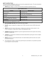
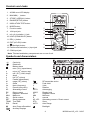
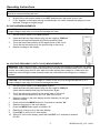
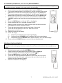
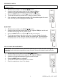
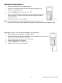
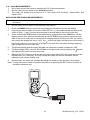
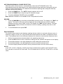
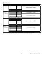
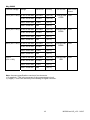
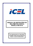
User's Guide Wireless TRMS Multimeter and Insulation Tester Model MG300 Introduction Congratulations on your purchase of the MG300 True RMS MultiMeter Insulation Resistance Tester. This meter measures AC/DC Voltage, AC/DC Current, Resistance, Capacitance, Frequency (electrical & electronic), Duty Cycle, Diode Test, Insulation Resistance, and Continuity plus Thermocouple Temperature. The MG300 can store and recall measurement data and features a waterproof, rugged design for heavy duty use. This meter can transmit data wirelessly when linked to a PC. Proper use and care of this meter will provide many years of reliable service. Safety This symbol adjacent to another symbol, terminal or operating device indicates that the operator must refer to an explanation in the Operating Instructions to avoid personal injury or damage to the meter. WARNING CAUTION MAX 1000V This WARNING symbol indicates a potentially hazardous situation, which if not avoided, could result in death or serious injury. This CAUTION symbol indicates a potentially hazardous situation, which if not avoided, may result damage to the product. This symbol advises the user that the terminal(s) so marked must not be connected to a circuit point at which the voltage with respect to earth ground exceeds (in this case) 1000 VAC or VDC. This symbol adjacent to one or more terminals identifies them as being associated with ranges that may, in normal use, be subjected to particularly hazardous voltages. For maximum safety, the meter and its test leads should not be handled when these terminals are energized. This symbol indicates that a device is protected throughout by double insulation or reinforced insulation. PER IEC1010 OVERVOLTAGE INSTALLATION CATEGORY OVERVOLTAGE CATEGORY I Equipment of OVERVOLTAGE CATEGORY I is equipment for connection to circuits in which measures are taken to limit the transient overvoltages to an appropriate low level. Note – Examples include protected electronic circuits. OVERVOLTAGE CATEGORY II Equipment of OVERVOLTAGE CATEGORY II is energy-consuming equipment to be supplied from the fixed installation. Note – Examples include household, office, and laboratory appliances. OVERVOLTAGE CATEGORY III Equipment of OVERVOLTAGE CATEGORY III is equipment in fixed installations. Note – Examples include switches in the fixed installation and some equipment for industrial use with permanent connection to the fixed installation. OVERVOLTAGE CATEGORY IV Equipment of OVERVOLTAGE CATEGORY IV is for use at the origin of the installation. Note – Examples include electricity meters and primary over-current protection equipment 2 MG300-en-US_v2.2 04/15 SAFETY INSTRUCTIONS This meter has been designed for safe use, but must be operated with caution. The rules listed below must be carefully followed for safe operation. 1. NEVER apply voltage or current to the meter that exceeds the specified maximum: Input Protection Limits Function V DC or V AC Maximum Input 1000VDC/AC rms mA AC/DC 500mA 1000V fast acting fuse A AC/DC 10A 1000V fast acting fuse (20A for 30 seconds max every 15 minutes) Frequency, Resistance, Capacitance, Duty Cycle, Diode Test, Continuity 1000VDC/AC rms Temperature 1000VDC/AC rms Surge Protection: 8kV peak per IEC 61010 2. USE EXTREME CAUTION when working with high voltages. 3. DO NOT measure voltage if the voltage on the "COM" input jack exceeds 1000V above earth ground. 4. NEVER connect the meter leads across a voltage source while the function switch is in the current, resistance, or diode mode. Doing so can damage the meter. 5. ALWAYS discharge filter capacitors in power supplies and disconnect the power when making resistance or diode tests. 6. ALWAYS turn off the power and disconnect the test leads before opening the covers to replace the fuse or batteries. 7. NEVER operate the meter unless the back cover and the battery and fuse covers are in place and fastened securely. 8. If the equipment is used in a manner not specified by the manufacturer, the protection provided by the equipment may be impaired. 3 MG300-en-US_v2.2 04/15 Controls and Jacks 1. 40,000 count LCD display 2. MAX/MIN ( - ) button 3. STORE (<RECALL) button 4. RANGE(SETUP) button 1 5. INSULATION TEST button 6. MODE button 2 4 7. Function switch 8. 10A input jack 3 5 6 9. mA, µA, Insulation (-) jack 10. HOLD (PEAKHOLD>) button 11 10 12 13 7 11. REL (+) button 12. EXIT (AC+DC) button 13. Backlight button 14. Positive and Insulation (+) input jack 8 14 9 15 15. COM input jack Note: Tilt stand and battery compartment are on rear of unit. Symbols and Annunciators •))) n µ m A k F M Hz % AC DC ºF MAX No. SET TRMS RCL Continuity Diode test Battery status -9 nano (10 ) (capacitance) -6 micro (10 ) (amps, cap) -3 milli (10 ) (volts, amps) Amps 3 kilo (10 ) (ohms) Farads (capacitance) 6 mega (10 ) (ohms) Ohms Hertz (frequency) Percent (duty ratio) Alternating current Direct current Degrees Fahrenheit Maximum Serial number Setup parameter True RMS Recall Auto Power off enabled PEAK V AUTO HOLD ºC MIN S AC +DC STO AUTO RF transmitter active Peak Hold Volts Relative Autoranging Display hold Degrees Celsius Minimum second Alternating current + Direct current Store Auto Range Backlight Auxiliary Displays 4 MG300-en-US_v2.2 04/15 Operating Instructions WARNING: Risk of electrocution. High-voltage circuits, both AC and DC, are very dangerous and should be measured with great care. 1. ALWAYS turn the function switch to the OFF position when the meter is not in use. 2. If “OL” appears in the display during a measurement, the value exceeds the range you have selected. Change to a higher range. DC VOLTAGE MEASUREMENTS CAUTION: Do not measure DC voltages if a motor on the circuit is being switched ON or OFF. Large voltage surges may occur that can damage the meter. 1. 2. 3. 4. Set the function switch to the VDC position. Insert the black test lead banana plug into the negative COM jack. Insert the red test lead banana plug into the positive V jack. Touch the black test probe tip to the negative side of the circuit. Touch the red test probe tip to the positive side of the circuit. Read the voltage in the display. AC VOLTAGE (FREQUENCY, DUTY CYCLE) MEASUREMENTS WARNING: Risk of Electrocution. The probe tips may not be long enough to contact the live parts inside some 240V outlets for appliances because the contacts are recessed deep in the outlets. As a result, the reading may show 0 volts when the outlet actually has voltage on it. Make sure the probe tips are touching the metal contacts inside the outlet before assuming that no voltage is present. CAUTION: Do not measure AC voltages if a motor on the circuit is being switched ON or OFF. Large voltage surges may occur that can damage the meter. 1. 2. Set the function switch to the VAC/Hz/% position. Insert the black test lead banana plug into the negative COM jack. Insert red test lead banana plug into the positive V jack. 3. Touch the black test probe tip to the neutral side of the circuit. Touch the red test probe tip to the “hot” side of the circuit. 4. Read the voltage in the main display and the frequency in the right auxiliary display 5. Press and hold the MODE button for 2 seconds to indicate “Hz”. 6. Read the frequency in the main display. 7. Press the MODE button again to indicate “%”. 8. Read the % of duty cycle in the main display. 9. Press EXIT to return to AC volts display 10. With ACV in the main display, press and hold EXIT for 2 seconds to measure AC+DC. 5 MG300-en-US_v2.2 04/15 mV VOLTAGE MEASUREMENTS CAUTION: Do not measure mV voltages if a motor on the circuit is being switched ON or OFF. Large voltage surges may occur that can damage the meter. 1. 2. 3. 4. 5. 6. Set the function switch to the mV position. Press the MODE button to indicate “DC” or “AC” In AC mode, press and hold EXIT for two seconds to select ”AC+DC” Insert the black test lead banana plug into the negative COM jack. Insert the red test lead banana plug into the positive V jack. Touch the black test probe tip to the negative side of the circuit. Touch the red test probe tip to the positive side of the circuit. Read the mV voltage in the main display. DC CURRENT MEASUREMENTS CAUTION: Do not make 20A current measurements for longer than 30 seconds. Exceeding 30 seconds may cause damage to the meter and/or the test leads. 1. 2. 3. 4. 5. 6. 7. 8. 9. Insert the black test lead banana plug into the negative COM jack. For current measurements up to 4000µA DC, set the function switch to the µA position and insert the red test lead banana plug into the µA/mA jack. For current measurements up to 400mA DC, set the function switch to the mA position and insert the red test lead banana plug into the µA/mA jack. For current measurements up to 20A DC, set the function switch to the 10A/HZ/% position and insert the red test lead banana plug into the 10A jack. Press the MODE button to indicate “DC” on the display. Remove power from the circuit under test, then open up the circuit at the point where you wish to measure current. Touch the black test probe tip to the negative side of the circuit. Touch the red test probe tip to the positive side of the circuit. Apply power to the circuit. Read the current in the display. AC+DC In the VAC, mV(AC), 10A(AC), mA(AC) and uA(AC) measurement modes, press the EXIT button for 2 seconds to enter AC+DC test mode. The LCD shows the AC+DC icon. Press EXIT to exit this mode. 6 MG300-en-US_v2.2 04/15 AC CURRENT (FREQUENCY, DUTY CYCLE) MEASUREMENTS CAUTION: Do not make 20A current measurements for longer than 30 seconds. Exceeding 30 seconds may cause damage to the meter and/or the test leads. 1. 2. Insert the black test lead banana plug into the negative COM jack. For current measurements up to 4000µA AC, set the function switch to the µA position and insert the red test lead banana plug into the µA/mA jack. 3. For current measurements up to 400mA AC, set the function switch to the mA position and insert the red test lead banana plug into the µA/mA jack. 4. For current measurements up to 20A AC, set the function switch to the 10A/HZ/% position and insert the red test lead banana plug into the 10A jack. 5. Press the MODE button to indicate “AC” on the display. 6. Press and hold EXIT for 2 seconds to select AC+DC. 7. Remove power from the circuit under test, then open up the circuit at the point where you wish to measure current. 8. Touch the black test probe tip to the neutral side of the circuit. Touch the red test probe tip to the “hot” side of the circuit. 9. Apply power to the circuit. 10. Read the current in the display. 11. In the 10A range: a) Frequency is displayed in the upper right display. b) Press and hold the MODE button to display “Hz” in the main display. c) Momentarily press the MODE button again to display “%” in the main display. 12. Press and hold the MODE button to return to current measurement. RESISTANCE MEASUREMENTS WARNING: To avoid electric shock, disconnect power to the unit under test and discharge all capacitors before taking any resistance measurements. Remove the batteries and unplug the line cords. 1. 2. 3. 4. 5. Set the function switch to the ΩCAP position. Insert the black test lead banana plug into the negative COM jack. Insert the red test lead banana plug into the positive jack. Press the MODE button to indicate “”on the display. Touch the test probe tips across the circuit or part under test. It is best to disconnect one side of the part under test so the rest of the circuit will not interfere with the resistance reading. Read the resistance in the display. 7 MG300-en-US_v2.2 04/15 CONTINUITY CHECK WARNING: To avoid electric shock, never measure continuity on circuits or wires that have voltage on them. 1. 2. 3. 4. 5. Set the function switch to the Ω CAP position. Insert the black lead banana plug into the negative COM jack. Insert the red test lead banana plug into the positive jack. Press the MODE button to indicate“ ” and “Ω” on the display Touch the test probe tips to the circuit or wire you wish to check. If the resistance is less than approximately 35, the audible signal will sound. If the circuit is open, the display will indicate “OL”. DIODE TEST 1. 2. Set the function switch to the Ω CAP position. Insert the black test lead banana plug into the negative COM jack and the red test lead banana plug into the positive V jack. 3. 4. Press the MODE button to indicate “ ” and “V” on the display. Touch the test probes to the diode under test. Forward voltage will typically indicate 0.400 to 0.700V. Reverse voltage will indicate “OL”. Shorted devices will indicate near 0V and an open device will indicate “OL” in both polarities. CAPACITANCE MEASUREMENTS WARNING: To avoid electric shock, disconnect power to the unit under test and discharge all capacitors before taking any capacitance measurements. Remove the batteries and unplug the line cords. 1. 2. 3. 4. 5. 6. Set the rotary function switch to the Ω CAP position. Insert the black test lead banana plug into the negative COM jack. Insert the red test lead banana plug into the positive V jack. Press the MODE button to indicate “F” Touch the test leads to the capacitor to be tested. Read the capacitance value in the display 8 MG300-en-US_v2.2 04/15 TEMPERATURE MEASUREMENTS 1. Set the function switch to the Temp position. 2. Insert the Temperature Probe into the input jacks, making sure to observe the correct polarity. 3. Press the MODE button to indicate “ºF” or “ºC” 4. Touch the Temperature Probe head to the part whose temperature you wish to measure. Touch the part under test with the probe until the reading stabilizes. 5. Read the temperature in the display. Note: The temperature probe is fitted with a type K mini connector. A mini connector to banana connector adaptor is supplied for connection to the input banana jacks. FREQUENCY (DUTY CYCLE) MEASUREMENTS (ELECTRONIC) 1. Set the rotary function switch to the Hz/% position. 2. Insert the black lead banana plug into the negative COM jack and the red test lead banana plug into the positive Hz jack. 3. Touch the test probe tips to the circuit under test. 4. Read the frequency on the display. 5. Press the MODE button to indicate “%”. 6. Read the % duty cycle in the display. 9 MG300-en-US_v2.2 04/15 % 4 – 20mA MEASUREMENTS 1. Set up and connect the meter as described for DC mA measurements. 2. Set the rotary function switch to the 4-20mA% position. 3. The meter will display loop current as a % with 0mA=-25%, 4mA=0%, 20mA=100%, and 24mA=125%. INSULATION RESISTANCE MEASUREMENTS Note: Disconnect the unit under test from all power sources and isolate it from any stray resistance. 1. 2. 3. 4. 5. Set the rotary function switch to the INSULATION position Press the RANGE button to select the test voltage as indicated on the top left display. Connect the red test lead to the meter’s INSULATION ( + ) jack and the black test lead to the INSULATION ( - ) jack. Connect the probe end of the test leads to the circuit under test. Press and hold the TEST button to test (alternatively, press and hold the LOCK key until the display shows LOCK and then momentarily press the TEST button to start a hands free test). Note: If the circuit under test is live and has a voltage potential (AC/DC) over 30V, the meter it will not test (the display will show “>30V”, the symbol will flash, and the buzzer will sound). If the circuit under test is not live or if its voltage is less than 30V, the meter will begin applying high-voltage to the circuit under test. The primary display and the analog bargraph will show the insulation resistance in MΩ. The test voltage (VDC) value will be indicated in the right-most auxiliary display, the symbol will flash and the caution buzzer will sound. 7. Release the TEST button to stop the test (to stop a hands free LOCK test, press and hold the release button for 2 seconds). The high voltage will switch off and the resistance values indicated in the primary display hold. 8. Subsequently, the meter will internally discharge the balance of the insulation test voltage. Note: Turning the function switch to another test position or pressing the EXIT button will abort an Insulation resistance test. 6. RANGE 10 MG300-en-US_v2.2 04/15 AUTORANGING/MANUAL RANGE SELECTION When the meter is first turned on, it automatically enters the AUTO RANGE mode. This automatically selects the best range for the measurements being made and is generally the best mode for most measurements. For measurement situations requiring that a range be manually selected, perform the following: 1. 2. 3. Press the RANGE key. The “AUTO” display indicator will turn off. Press the RANGE key to step through the available ranges. To exit the MANUAL RANGE mode, press EXIT Note: MANUAL RANGE is not available for the Temperature functions. MAX/MIN 1. Press the MAX/MIN key to activate the MAX/MIN recording mode. The display icon "MAX" will appear. The meter’s left-most auxiliary display will show and hold the maximum reading, updating only when a new “MAX” occurs. The display icon "MIN" will then appear. The rightmost auxiliary display will show and hold the minimum reading, updating only when a new “MIN” occurs. 2. To exit MAX/MIN mode press EXIT. RELATIVE MODE The relative measurement mode displays readings that are relative to a stored reference value. A reference voltage, current, etc. can be stored and measurements are made in comparison to that value. The displayed value is the difference between the reference value and the measured value. 1. 2. 3. 4. 5. Perform the measurement as described in the operating instructions. Press the REL button to store a reference reading; the "▲" indicator will appear on the display. The auxiliary display on the right displays the initial reading (the stored value). The auxiliary display on the left displays the actual currently measured value. The main display shows the Relative value (measured value minus the stored value). AC+DC In the VAC, mV(AC), 10A(AC), mA(AC) and uA(AC) measurement modes, press the EXIT button for 2 seconds to enter AC+DC test mode. The LCD shows the AC+DC icon. Press EXIT to exit this mode. 11 MG300-en-US_v2.2 04/15 DISPLAY BACKLIGHT Press the key to switch the backlight on. The backlight will automatically switch off after the SET time has expired. Press the EXIT button to exit the backlight on mode. HOLD The hold function freezes the reading in the display. Press the HOLD key momentarily to activate or to exit the HOLD function. PEAK HOLD The Peak Hold function captures the peak AC or DC voltage or current. The meter can capture negative or positive readings as fast as 1 millisecond in duration. Momentarily press the PEAK button, “PEAK” and “MAX” will display in the left auxiliary display. MIN” will display in right auxiliary display. The meter will update the dispay each time a greater value occurs. Press the EXIT button to exit the PEAK HOLD mode. Auto Power Off feature will be disabled automatically in this mode. DATA STORAGE 1. Set the function switch to the measurement function desired. 2. Press the STORE button to access the recording interval time set up function. 3. The auxiliary display on the left indicates 0000 S, which is the recording sample rate; use the + & - buttons to select the desired sample rate (0 to 255 seconds) 4. Set the sample rate to 0000 S for manual recording. In this mode, each press of the STORE button will save one measurement reading. 5. Set the sample rate (from 1 to 255 S) for automatic recording. In this mode, pressing the STORE button will start data recording at the programmed sample rate. 6. The auxiliary display on the left indicates the current storage location (0000 to 9999). New measurements will begin storing into the next available location. 7. Press and hold the STORE button for 2 seconds to enter the RECALL mode or press EXIT to return to the normal operating mode. DATA STORAGE RECALL 1. Press and hold the STORE button for two seconds (if not already done as instructed in step 7 in the above procedure) to enter the RECALL function. 2. The auxiliary display on the left will show XXXX (current storage location). The auxiliary display on the right will show XXXX (number of storage locations used). 3. Use the + and - buttons to navigate the storage locations. The value for the selected location is indicated in the main display. 4. Press the EXIT button to end the recall session. CLEAR ALL DATA 1. From the OFF position, press and hold the RANGE button while turning the function switch to any on position 2. Release the RANGE button. The memory has been cleared. 12 MG300-en-US_v2.2 04/15 PC WIRELESS COMMUNICATION 1. Install and launch the PC software (refer to the HELP utility contained in the software for more details) 2. Press and Hold the backlight/USB button for two seconds to enter RF wireless transmit mode 3. 4. 5. 6. will appear on the display The RF icon When communication is established, the RF icon on the display will blink and the LED indicator on the receiver will blink Once per second, the data will be displayed on the PC screen (plotted on the graph and inserted to the data list) Hold the backlight button for two seconds to exit the RF wireless transmit mode SENDING STORED DATA TO THE PC 1. Launch the PC software 2. Press the Play button ► to start a Real Time measurement. 3. Enter 8000 into the Samples field and click OK. 4. Choose Data Graph or Data List. Note: do not press the USB button to turn on wireless. 5. On the Meter, Press the STORE button for two seconds to enter into data RECALL function. 6. Press the HOLD button for two seconds. The RF transmit icon will flash while the stored data is sent to the PC SETUP 1. Press and Hold the RANGE/SETUP button for two seconds to enter the SET function. The first of five settable functions will appear. 2. Press the RANGE button to step through the functions a: Alarm High limit buzzer alarm OFF or Value b: Alarm Low limit buzzer alarm OFF or Value c: Auto power off time OFF, 10 to 30 sec d: Button beeper ON/OFF e : Back light time OFF, 10 to 30 sec 3. Use the +, - ,◄ and ► buttons to select and change conditions and digits. 4. Press the RANGE/SETUP button until the meter returns to the normal display to exit this mode. ALARM LIMITS 1. Press and Hold the SETUP button for two seconds to enter the High Limit function. 2. Press the ► button to select a digit for adjustment 3. Press the + or – button to adjust the value of the digit 4. 5. 6. 7. Press the ◄ button to turn the alarm OFF. Press the SETUP button and repeat the procedure to set the low limit Press the SETUP button to step through the other functions and return to the normal operating mode. The meter will “beep” if the measured value is greater than the high limit or lower than the low limit. LOW BATTERY INDICATION When the icon appears in the display, the battery should be replaced. 13 MG300-en-US_v2.2 04/15 Maintenance WARNING: To avoid electric shock, disconnect the test leads from any source of voltage before removing the back cover or the battery or fuse covers. WARNING: To avoid electric shock, do not operate your meter until the battery and fuse covers are in place and fastened securely. This MultiMeter is designed to provide years of dependable service, if the following care instructions are performed: 1. KEEP THE METER DRY. If it gets wet, wipe it off. 2. USE AND STORE THE METER IN NORMAL TEMPERATURES. Temperature extremes can shorten the life of the electronic parts and distort or melt plastic parts. 3. HANDLE THE METER GENTLY AND CAREFULLY. Dropping it can damage the electronic parts or the case. 4. KEEP THE METER CLEAN. Wipe the case occasionally with a damp cloth. DO NOT use chemicals, cleaning solvents, or detergents. 5. USE ONLY FRESH BATTERIES OF THE RECOMMENDED SIZE AND TYPE. Remove old or weak batteries so they do not leak and damage the unit. 6. IF THE METER IS TO BE STORED FOR A LONG PERIOD OF TIME, the batteries should be removed to prevent damage to the unit. BATTERY INSTALLATION WARNING: To avoid electric shock, disconnect the test leads from any source of voltage before removing the battery cover. 1. Turn power off and disconnect the test leads from the meter. 2. Open the rear battery cover by removing four screws using a Phillips head screwdriver. 3. Insert the battery into battery holder, observing the correct polarity. 4. Put the battery cover back in place. Secure with the screws. You, as the end user, are legally bound (EU Battery ordinance) to return all used batteries, disposal in the household garbage is prohibited! You can hand over your used batteries / accumulators at collection points in your community or wherever batteries / accumulators are sold! Disposal: Follow the valid legal stipulations in respect of the disposal of the device at the end of its lifecycle WARNING: To avoid electric shock, do not operate your meter until the battery cover is in place and fastened securely. 14 MG300-en-US_v2.2 04/15 REPLACING THE FUSES WARNING: To avoid electric shock, disconnect the test leads from any source of voltage before removing the meter cover. 1. Disconnect the test leads from the meter. 2. To replace the 500mA fuse only, remove the battery cover (four screws); the 500mA fuse will be visible and accessible. 3. To replace the 10A fuse, remove the six screws securing the rear cover and remove the rear cover. 4. Gently remove the old fuses and install the new fuses into the holders. 5. Always use a fuse of the proper size and value (0.5A/1000V fast blow for the 400mA range [SIBA 70-172-40], 10A/1000V fast blow for the 20A range [SIBA 50-199-06]). 6. Replace and secure the rear cover, battery and battery cover. WARNING: To avoid electric shock, do not operate your meter until the fuse cover is in place and fastened securely. FCC Part 15 This equipment has been tested and found to comply with the limits for a Class B digital device, pursuant to part 15 of the FCC Rules. These limits are designed to provide reasonable protection against harmful interference in a residential installation. This equipment generates, uses and can radiate radio frequency energy and, if not installed and used in accordance with the instructions, may cause harmful interference to radio communications. However, there is no guarantee that interference will not occur in a particular installation. If this equipment does cause harmful interference to radio or television reception, which can be determined by turning the equipment off and on, the user is encouraged to try to correct the interference by one or more of the following measures: —Reorient or relocate the receiving antenna. —Increase the separation between the equipment and receiver. —Connect the equipment into an outlet on a circuit different from that to which the receiver is connected. —Consult the dealer or an experienced radio/TV technician for help. Warning: Changes or modifications not expressly approved by the party responsible for compliance could void the user's authority to operate the equipment. 15 MG300-en-US_v2.2 04/15 Specifications Function DC Voltage AC Voltage (AC+DC) 50 to 1000Hz DC Current Range 400mV 4V 40V 400V 1000V Resolution 0.01mV 0.0001V 0.001V 0.01V 0.1V 400A 0.01A Accuracy (0.06% reading + 4 digits) (0.1% reading + 5 digits) 400mV 0.1mV (1.0% reading + 7 digits) 4V 0.001V 40V 0.01V 400V 0.1V (1.0% reading +5 digits) 1000V 1V All AC voltage ranges are specified from 5% of range to 100% of range 4000A 0.1A 40mA 0.001mA 400mA 0.01mA 10A 0.001A (20A: 30 sec max with reduced accuracy) AC Current (AC+DC) 50 to 1000Hz 400A (1.0% reading + 3 digits) 0.1A 4000A 1A (1.5% reading +7 digits) 40mA 0.01mA 400mA 0.1mA 10A 0.01A (20A: 30 sec max with reduced accuracy) All AC voltage ranges are specified from 5% of range to 100% of range o o o o NOTE: Accuracy is stated at 65 F to 83 F (18 C to 28 C) and less than 75% RH. 16 MG300-en-US_v2.2 04/15 Function Resistance Capacitance Frequency (electronic) Frequency (electrical) Duty Cycle Range Resolution 400 0.01 4k 0.0001k 40k 0.001k 400k 0.01k 4M 0.0001M 40M 40nF 400nF 0.001M 0.001nF 0.01nF 4F 0.0001F 40F 0.001F Accuracy (0.3% reading + 9 digits) (0.3% reading + 4 digits) (2.0% reading + 10 digits) (3.5% reading + 40 digits) (3.5% reading + 10 digits) 400F 0.01F 4mF 0.0001mF (5% reading + 10 digits) 40mF 0.001mF 40Hz 0.001Hz 400Hz 0.01Hz 4kHz 0.0001kHz 40kHz 0.001kHz (0.1% reading + 1 digits) 400kHz 0.01kHz 4MHz 0.0001MHz 40MHz 0.001MHz 100MHz 0.01MHz Not specified Sensitivity: 0.8V rms min. @ 20% to 80% duty cycle and <100kHz; 5Vrms min @ 20% to 80% duty cycle and > 100kHz. 40.00HZ-4KHz 0.01HZ to (0.5% reading) 0.001KHz Sensitivity:5Vrms 0.1 to 99.90% 0.01% (1.2% reading + 2 digits) Pulse width: 100µs - 100ms, Frequency: 5Hz to 150kHz (1.0% reading + 4.5°F) (1.0% reading + 2.5°C) (probe accuracy not included) 4-20mA% -25 to 125% 0.01% ±50 digits 0mA=-25%, 4mA=0%, 20mA=100%, 24mA=125% Note: Accuracy specifications consist of two elements: (% reading) – This is the accuracy of the measurement circuit. (+ digits) – This is the accuracy of the analog to digital converter. Temp (type-K) -58 to 1832F 0.1F -50 to 1000C 0.1C 17 MG300-en-US_v2.2 04/15 Meg OHMS Terminal Voltage Range Resolution Accuracy Test current Short circuit current 125V (0%~+10%) 0.125~4.000 MΩ 0.001MΩ 4.001~40.00 MΩ 0.01MΩ +(2%+10) 40.01~400.0 MΩ 0.1MΩ +(4%+5) 400.1~4000 MΩ +(5%+5) 1MΩ 250V (0%~+10%) 0.250~4.000 MΩ 0.001MΩ (0%~+10%) +(2%+10) 4.001~40.00 MΩ 0.01MΩ +(2%+10) 40.01~400.0 MΩ 0.1MΩ +(3%+5) 400.1~4000 MΩ +(4%+5) 1MΩ 500V (0%~+10%) 0.500~4.000 MΩ 0.001MΩ 1000V +(2%+10) +(2%+10) 4.001~40.00 MΩ 0.01MΩ +(2%+10) 40.01~400.0 MΩ 0.1MΩ +(2%+5) 400.1~4000 MΩ +(4%+5) 1MΩ 1.000~4.000 MΩ 0.001MΩ +(3%+10) 4.001~40.00 MΩ 0.01MΩ +(2%+10) 40.01~400.0 MΩ 0.1MΩ +(2%+5) 400.1~4000 MΩ +(4%+5) 1MΩ 1mA @ load ≤1mA 125kΩ 1mA @ load ≤1mA 250kΩ 1mA @ load ≤1mA 500kΩ 1mA @ load ≤1mA 1MΩ Note: Accuracy specifications consist of two elements: (% reading) – This is the accuracy of the measurement circuit. (+ digits) – This is the accuracy of the analog to digital converter. 18 MG300-en-US_v2.2 04/15 Enclosure Shock (Drop Test) Diode Test Storage capacity RF transmit distance Transmitter Frequency Continuity Check Peak Temperature Sensor Input Impedance AC Response ACV Bandwidth Crest Factor Display Overrange indication Auto Power Off Polarity Measurement Rate Double molded, waterproof (IP67) 6.5 feet (2 meters) Test current 0.9mA maximum, open circuit voltage 2.8V DC typical 8000 records 10 meters (approx) 915MHz Audible signal will sound if the resistance is less than 35 (approx.), test current <0.35mA Captures peaks >1ms Requires type K thermocouple >10MΩ VDC & >9MΩ VAC True rms 50Hz to 1000Hz ≤3 at full scale up to 500V, decreasing linearly to ≤1.5 at 1000V 40,000 count, backlit, liquid-crystal display with bargraph “OL” is displayed 15 minutes (approximately) with disable feature Automatic (no indication for positive); Minus (-) sign for negative 2 times per second, nominal Low Battery Indication Battery Fuses “ ” is displayed if battery voltage drops below operating voltage Six (6) 1.5V ‘AA’ batteries mA, µA ranges; 0.5A/1000V ceramic fast blow (SIBA 70-172-40) A range; 10A/1000V ceramic fast blow (SIBA 50-199-06) Operating Temperature 41ºF to 104ºF (5ºC to 40ºC) o o o o Storage Temperature -4 F to 140 F (-20 C to 60 C) Operating Humidity Max 80% up to 87ºF (31ºC) decreasing linearly to 50% at 104ºF (40ºC) Storage Humidity <80% Operating Altitude 7000ft (2000meters) maximum Weight 20.5 oz. (582g) Size 7.8” x 3.6” x 1.9” (200 x 92 x 50mm) Safety This meter is intended for origin of installation use and protected, against nd the users, by double insulation per EN61010-1 and IEC61010-1 2 Edition (2001) to Category IV 600V and Category III 1000V; Pollution Degree 2. 19 MG300-en-US_v2.2 04/15 Warranty FLIR Systems, Inc. warrants this Extech Instruments brand device to be free of defects in parts and workmanship for one year from date of shipment (a six month limited warranty applies to sensors and cables). If it should become necessary to return the instrument for service during or beyond the warranty period, contact the Customer Service Department for authorization. Visit the website www.extech.com for contact information. A Return Authorization (RA) number must be issued before any product is returned. The sender is responsible for shipping charges, freight, insurance and proper packaging to prevent damage in transit. This warranty does not apply to defects resulting from action of the user such as misuse, improper wiring, operation outside of specification, improper maintenance or repair, or unauthorized modification. FLIR Systems, Inc. specifically disclaims any implied warranties or merchantability or fitness for a specific purpose and will not be liable for any direct, indirect, incidental or consequential damages. FLIR’s total liability is limited to repair or replacement of the product. The warranty set forth above is inclusive and no other warranty, whether written or oral, is expressed or implied. Calibration, Repair, and Customer Care Services FLIR Systems, Inc. offers repair and calibration services for the Extech Instruments products we sell. NIST certification for most products is also provided. Call the Customer Service Department for information on calibration services available for this product. Annual calibrations should be performed to verify meter performance and accuracy. Technical support and general customer service is also provided, refer to the contact information provided below. Support Lines: U.S. (877) 439‐8324; International: +1 (603) 324‐7800 Technical Support: Option 3; E‐mail: [email protected] Repair & Returns: Option 4; E‐mail: [email protected] Product specifications are subject to change without notice Please visit our website for the most up‐to‐date information www.extech.com FLIR Commercial Systems, Inc., 9 Townsend West, Nashua, NH 03063 USA ISO 9001 Certified Copyright © 2013 – 2015 FLIR Systems, Inc. All rights reserved including the right of reproduction in whole or in part in any form www.extech.com 20 MG300-en-US_v2.2 04/15 Garantie FLIR Systems, Inc. garantit que cet appareil Extech Instruments est exempt de défauts matériaux et de fabrication pendant un an à partir de la date d’envoi (une garantie limitée de six mois s’applique aux capteurs et aux câbles). Si le renvoi de l’appareil pour réparation devient nécessaire durant ou après la période de garantie, contactez le service client pour autorisation. Pour obtenir les coordonnées, visitez le site Web suivant : www.extech.com. Un numéro d’autorisation de retour (AR) doit être délivré avant tout retour de produit. L’expéditeur prend à sa charge les frais d’expédition, le fret, l’assurance et l’emballage correct de l’appareil afin de prévenir toute détérioration durant le transport. Cette garantie ne s’applique pas aux dommages imputables à l’utilisateur, tels que l’usage impropre ou abusif, un mauvais câblage, une utilisation non conforme aux spécifications, un entretien ou une réparation incorrecte, ou toute modification non autorisée. FLIR Systems, Inc. déclinera spécifiquement toute garantie ou qualité marchande ou aptitude à l’emploi prévu, et ne sera en aucun cas tenu responsable pour tout dommage conséquent, direct, indirect ou accidentel. La responsabilité totale de FLIR est limitée à la réparation ou au remplacement du produit. La garantie définie ci‐dessus est inclusive et aucune autre garantie, écrite ou orale, n’est exprimée ou implicite. Calibrage, réparation et services après‐vente FLIR Systems, Inc. offre des services de calibrage et de réparation pour les produits Extech Instruments que nous commercialisons. Nous fournissons également une certification NIST pour la plupart des produits. Contactez notre service client pour toute information sur les services de calibrage disponibles pour ce produit. Un calibrage doit être effectué chaque année pour vérifier les performances et la précision du mètre. Nous offrons également une assistance technique et un service à la clientèle. Veuillez vous reporter aux coordonnées fournies ci‐dessous. Lignes d’assistance: États‐Unis (877) 439‐8324; international: +1 (603) 324‐7800 Service d’assistance technique : Option 3 ; E‐mail : [email protected] Réparations et retours : Option 4 ; E‐mail : [email protected] Les spécifications produit sont sujettes à modifications sans préavis. Pour les toutes dernières informations, veuillez visiter notre site Web. www.extech.com FLIR Commercial Systems, Inc., 9 Townsend West, Nashua, NH 03063 USA Certifié ISO 9001 Copyright © 2013 ‐ 2015 FLIR Systems, Inc. Tous droits réservés, y compris la reproduction partielle ou totale sous quelque forme que ce soit. www.extech.com 21 MG300-en-US_v2.2 04/15 Garantía FLIR Systems, Inc., garantiza este dispositivo marca Extech Instruments para estar libre de defectos en partes o mano de obra durante un año a partir de la fecha de embarque (se aplica una garantía limitada de seis meses para cables y sensores). Si fuera necesario regresar el instrumento para servicio durante o después del periodo de garantía, llame al Departamento de Servicio a Clientes para obtener autorización. Visite www.extech.com para Información de contacto. Se debe expedir un número de Autorización de Devolución (AD) antes de regresar cualquier producto. El remitente es responsable de los gastos de embarque, flete, seguro y empaque apropiado para prevenir daños en tránsito. Esta garantía no se aplica a defectos resultantes de las acciones del usuario como el mal uso, alambrado equivocado, operación fuera de las especificaciones, mantenimiento o reparación inadecuada o modificación no autorizada. FLIR Systems, Inc., rechaza específicamente cualesquier garantías implícitas o factibilidad de comercialización o idoneidad para cualquier propósito determinado y no será responsable por cualesquier daños directos, indirectos, incidentales o consecuentes. La responsabilidad total de FLIR está limitada a la reparación o reemplazo del producto. La garantía precedente es inclusiva y no hay otra garantía ya sea escrita u oral, expresa o implícita. Servicios de calibración, reparación y atención a clientes FLIR Systems, Inc., ofrece servicios de reparación y calibración para los productos que vendemos de Extech Instruments. Además ofrecemos certificación NIST para la mayoría de los productos. Llame al Departamento de Servicio al Cliente para solicitar información de calibración para este producto. Para verificar el funcionamiento y precisión se debe realizar la calibración anual. Además se provee Soporte Técnico y servicios generales al cliente, consulte la información de contacto en seguida. Líneas de soporte: EE.UU. (877) 439‐8324; Internacional: +1 (603) 324‐7800 Soporte Técnico Opción 3; correo electrónico: [email protected] Reparación / Devoluciones: Opción 4; correo electrónico: [email protected] Las especificaciones del producto están sujetas a cambios sin aviso Por favor visite nuestra página en Internet para la información más actualizada www.extech.com FLIR Commercial Systems, Inc., 9 Townsend West, Nashua, NH 03063 USA Certificado ISO 9001 Copyright © 2013 ‐ 2015 FLIR Systems, Inc. Reservados todos los derechos, incluyendo el derecho de reproducción total o parcial en cualquier medio www.extech.com 22 MG300-en-US_v2.2 04/15