1
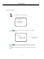
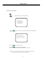
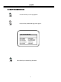
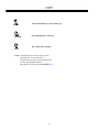
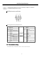
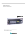
INSTRUCTION MANUAL Digital Single Channel Recorder EDSR100 V1.3 About this manual Before installing and using this unit, please read this Manual carefully. Be sure to keep it handy for later reference. Safety Warning WARNING TO REDUCE RISK OF FIRE OR ELECTRIC SHOCK, DO NOT EXPOSE THIS APPLIANCE TO RAIN OR MOISTURE. CAUTION DO NOT REMOVE COVER. NO USER SERVICEABLE PARTS INSIDE. REFER SERVICING TO QUALIFIED SERVICE PERSONNEL. Note: This equipment has been tested and found to comply with the limits for a Class B digital device, pursuant to Part 15 of the FCC Rules. These limits are designed to provide reasonable protection. This equipment generates, uses and can radiated radio frequency energy and, if not installed and used in accordance with the instructions, may cause harmful interference to radio communications. However, there is no guarantee that interference will not occur in a particular installation If this equipment does cause harmful interference to radio or television reception, which can be determined by turning the equipment off and on, the user is encouraged to try to correct the interference by one or more of the following measures: -Reorient or relocate the receiving antenna. -Increase these paration between the equipment and receiver. -Connect the equipment into an outlet on a circuit different from that to which the receiver is connected. -Consult the dealer or an experienced radio/TV technician for help. The changes or modifications not expressly approved by the party responsible for compliance could void the user's authority to operate the equipment. Notice: The information in this manual was current when published. The manufacturer reserves the right to revise and improve its products. All specifications are therefore subject to change without notice. Safety Precautions Safety Precautions Refer all work related to the installation of this product to qualified service personnel or system installers. Do not block the ventilation opening or slots on the cover. Do not drop metallic parts through slots.This could permanently damage the appliance. Turn the power off immediately and contact qualified service personnel for service. Do not attempt to disassemble the appliance.To prevent electric shock, do not remove screws or covers. There are no user-serviceable parts inside. Contact qualified service personnel for maintenance. Handle the appliance with care. Do not strike or shake, as this may damage the appliance. Do not expose the appliance to water or moisture, nor try to operate it in wet areas. Do take immediate action if the appliance becomes wet. Turn the power off and refer servicing to qualified service personnel. Moisture may damage the appliance and also cause electric shock. Do not use strong or abrasive detergents when cleaning the appliance body. Use a dry cloth to clean the appliance when it is dirty. When the dirt is hard to remove,use a mild detergent and wipe gently. Do not overload outlets and extension cords as this may result in a risk of fire or electric shock. Do not operate the appliance beyond its specified temperature, humidity or power source ratings. Do not use the appliance in an extreme environment where high temperature or high humidity exists. Use the appliance at temperature within 0oC ~ +50oC and a humidity below 90%. The input power source for this appliance is AC90~265V. Safety Precautions Safety Precautions The lightning flash with an arrowhead symbol, within an equilateral triangle, is intended to alert the user to the presence of uninsulated ” dangerous voltage” within the product’s enclosure that may be of sufficient magnitude to constitute a risk of electric shock to persons The exclamation point within an equilateral triangle is intended to alert the user to presence of important operating and maintenance(servicing)instructions in the literature accompanying the appliance. Warning : To prevent fire or shock hazard, do not expose units not specifically designed for outdoor use to rain or moisture. Attention: Installation should be performed by qualified service personnel only in accordance with the National Electrical Code or applicable local codes. Power Disconnect: Units with or without ON-OFF switches have power supplied to the unit whenever the power code is inserted into the power source; however, the unit is operational only when the ON-OFF switch is in the ON position. The power cord is the main power disconnect for all units. External Power Supplies Use only the recommended power supplies. Power supplies must comply with the requirement of the latest version of IEC 60065/CNS 13439. Substitutions may damage the unit or cause a fire or shock hazard 110V,60Hz Power Cords 110V,60Hz power cords, input and output, must comply with the latest versions of IEC 60065/CNS 13439 Warning: Electrostatic-sensitive device. Use proper CMOS/MOSFET handing precautions to avoid electrostatic discharge. UNPACKING Unpack carefully. This is electronic equipment and should be handled carefully. Check to ensure that the following items are included; •1. •2. •3. •4. Digital Single Channel Recorder User’s manual CF card reader Power Cord If an item appears to have been damaged in shipment, replace it properly in its carton and notify the shipper. If any items are missing, notify your Everfocus Electronics Corp. Sales Representative or Customer Service. The shipping carton is the safest container in which the unit may be transported. Save it for possible future use. Service If the unit ever needs repair service, the customer should contact the nearest Everfocus Electronics Corp. Service Center for return authorization and shipping instruction. Important Safeguards Important Safeguards Read Instruction---All the safety and operating instructions should be read before the init is operated Retain Instructions---The safety and operating instructions should be retained for future reference. Heed Warnings—All warnings on the unit and in the operating instructions should be adhered to. Follow Instructions—All operating and use instructions should be followed Cleaning—Unplug the unit from the outlet before cleaning. Do not use liquid cleaners or aerosol cleaners. Use a damp cloth for cleaning Attachments—Do not use attachment not recommended by the product manufacturer as they may cause hazards. Water and Moisture—Do not use this unit near water-for example, near a bath tub, wash bowl, kitchen sink, or laundry tub, in a wet basement, near a swimming pool, in an unprotected outdoor installation, or any area which is classified as a wet location. Servicing—Do not attempt to service this unit yourself as opening or removing covers may expose you to dangerous voltage or other hazards. Refer all servicing to qualified service personnel. Power Cord Protection—Power supply cords should be routed so that they are not likely to be walked on or pinched by items placed upon or against them, playing particular attention to cords and plugs, convenience receptacles, and the point where they exit from the appliance. Object and Liquid Entry—Never push objects of any kind into this unit through openings as they may touch dangerous voltage points or short-out parts that could result in a fire or electric shock, Never spill liquid of any kind on the unit. Table of Contents 1. Product Overview……….…...……………………………………………………………………………………..………….. 1 1.1 Feature………...…….…….….…………………………………….…………..……………………………………………..1 1.2 Specifications………....………………….………………………………..………….……………………………………...2 2. Front & Rear Panels………...…….………………………………………..…………………………………………………....3 3. Back Panel Connections…….………...……………………………………..…………………………………………………..6 4. System Connection…....………………………...…………………………..…………….…………………….………………..9 4.1 One Camera Connection………….…..…….………………………………………………………..……………………….9 4.2 Multiplexer Connection...……….….……………………………………………………………...………………………..10 4.3 Quad Connection ( with VCR )………….……………….………………………………………..……………………… 11 4.4 Quad Connection ( without VCR)….….………….……………...……………………………………………………...….12 5. Installation………...………………………………………………..……………….….……………………………………….13 6. Menu………...……………….……………………………………..……………………………………………………………14 6.1 Clock/Language Setup…...………….………….…….…………………………………………………………………….15 6.2 Timer-Set Setting Menu..…………………...…….……….………………………...……………………………………...16 6.3 Normal Record Setting Menu……………….…..…………………………………………………...…………………..….18 6.4 Alarm Record Setting Menu…………………….………..……………………………………………………………...….20 6.5 Buzzer Setting Menu…………………….………………………………………………………….………………………22 6.6 Archive Setting Menu…………………...….…………….…………………………...…………………………………….23 6.7 Network Setting Menu…...……………………………………..……………………………………………………………24 6.8 System Setting Menu…………………………………………………………………………………………………………26 7. Recording…...……………...……………………………………………………………..……………………………………. 28 7.1 Instant Recording……………..…………………………………………………….……………………………………... 28 7.2 Alarm Recording……………………………………………………………………………….………………………….. 29 8. Playback…...…………………………………………………….……………………….…………………………………..… 30 8.1 Normal Playback…………………………………………………………………………………………………………... 30 8.2 Search Playback…………………………………………………………………………………………………………… 32 9. Copy………...……………………….…………………………………………………………….…………………….………35 9.1 Still Image Copy……………………………………………………………………………………………………………35 9.2 Copy to Movie File……...………………………………………………………………………………………………….36 10. Interface Specifications……..….……...……………………………………………………………………………………...38 10.1 Transmission setting……..……………………………..………………………….………………………………………38 10.2 Remote Control Protocol…………………………………..………………………………………………………..……..39 11. Remote Controller………….…….……………………………………………………………………………...……………40 12. Appendix-A/Time Lapse Mode Recording Time…….……..………………………………………………………....….....41 12.1 Recording with and 80 GB HDD…..…………...………………….…………………………………………….………..41 12.2 Recording with and 160 GB HDD…………..…………………………………………………………………………….42 13. Appendix-B/ Security Lock setting..…...…….………………………………………………………………………………43 14. Appendix-C/ View From Internet/Intranet……….…...……………………………………………………………….……44 Product Overview and Features 1. Product Overview The EDSR100 is the first true VCR replacement designed particularly for the security industry, seamlessly combining high-resolution video multiplexing and digital recording. The EDSR100 at speeds up to 60/50 images per second with NTSC/PAL formats and replay event instantly. The EDSR100 incorporates all the benefits of digital video recording, is simple to install, and operates just like a VCR. The highly efficient compression technology, as well as the superior clarity and detail of recorder images, make the EDSR100 stand out from its competitors as the best choice for security surveillance. 1.1 Features Digital Recording provides superior quality images Hard-disk hot-swapping capability Pre-Alarm image recording Compatible with most multiplexers Time lapse and real time recording Refresh rate up to 60 field (50 field for PAL) Quick Search by date/time, alarm events, and recording list Fast and slow playback of recorded video in various speeds On-screen setup menu and system timer Multi-level password protection RS-232 communication port Highly stable non-PC based proprietary system Built-in M-JPEG compression/decompression with configurable quality Audio recording capability Programmed with various time-lapse speeds, Data can be stored in Compact Flash Card. Operation status record log 1 Specifications 1.2 Specifications Video Input 1 video input with loop through (BNC), 1Vpp/75ohm;1S-Video input Video Output 1 video output (BNC), 1Vpp/75ohm;1S-Video output Video Compression M-JPEG Video Resolution 720x484 (NTSC); 720x576 (PAL) CompactFlash Memory Yes, Built-in Compact Flash card slot Alarm Input Yes Alarm Output Yes Audio 2 input; 2 output Video Loss Detection Yes Ethernet RJ45 connector Event Log Yes Hard Disk Storage 3.5” IDE type, Hot- swappable Recording Mode Continuous, Time-lapse recording, Timer or Event Recording Recording Rate 60/50 field per second for NTSC/PAL Playback Rate 60/50 field per second for NTSC/PAL Playback Search Date/Time or Event Setup On screen display setup User Interface Menu Driven User Input Device Front Panel Keypad Timer Built-in real time clock Watch Dog Timer Yes RS-232 9-pin female connector Power Source AC90~265V Dimension 430mm (L) x 88mm (W) x 300mm (H) Operating Temperature 0℃~+50℃ Power Consumption 39W 2 Front Panel Keypads 2. Front Panel Keypads 20 17 18 19 16 15 1 LED 2 5 6 7 8 9 10 11 12 4 3 14 1 HDD : HDD Access, the LED will be lit when HDD is accessed. 2 LAN : LAN Access, the LED will be lit when LAN is accessed. 3 ALARM : The LED will be lit when alarm occurs. 4 POWER : Indicates the power is normal. 13 Keys 5 REC : Press this key to start recording. 6 REV. PLAY : Reverse Play Back. The playback speed is shown on the LCD display, and press to change the speed if necessary. 7 STOP : Press this key to stop recording and play back. 8 PLAY: Play Back. The playback speed is shown on the LCD display, and press to change the speed if necessary. 9 PAUSE: Press this key to pause the playback picture. 10 SEARCH: Press this key to enter the Search Playback Menu. 11 COPY: Press this key to start copy still picture or video stream into Compact Flash card. 12 Display: Press this switch ON/OFF the display. 50 % 2002/04/24 WED 12:00:00 Display OFF Display Date/Time and HDD available space 3 Buzzer : Enable Disk Size (GB) : 80.01 Record Position : 50% Play Position : 49% Record Quality : STANDARD 50 % 2002/04/24 WED 12:00:00 Display Date/Time HDD available space Recording setting Disk size Play position Front Panel Keypads 13 ENTER : Press this key to confirm the selection or data changed. 14 MENU : Press this key to enter Setup menu. 15 Remote Control 16 Jog and Shuttle Dial IR Remote receiver Shuttle Dial : In Playback mode, turning the shuttle dial can fast forward/rewind the picture. In Pause mode, turning the shuttle dial can slow forward/rewind the picture. In Menu mode, turning the shuttle dial can change menu page forward/rewind. Jog Dial 17 : In Pause mode, turn the jog dial can forward/rewind the Picture by one frame. In Menu mode turning the jog dial clockwise increases the cursor data which show on the system. Turning the jog dial counterclockwise decreases the cursor data which show on the system. Up/ Down : (1) In Menu mode, press those keys to change data. (2) In Record/Playback mode, press those keys to change the Record/Playback speed. Left/ Right : In Menu mode, these keys are used to move cursor. 18 LCD Display 2002/04/24 12:00:00 2002/04/24 12:00:00 SYS LOAD 002 HR Switch on the power, “system loading” will be shown ten seconds, both in LCD display & main monitor. STANDARD 002 HR In Standby mode, the date/time is current date/time and the right part shows the quality and rate setting for normal recording. 4 Front Panel Keypads 2002/04/24 12:00:00 RECORD . 002 HR 2002/04/24 12:00:00 PLAY > 002 HR In Recording mode, the date/time is current date/time and the right part shows RECORD and current recording rate. In Playback mode, the date/time is the playback date/time and the right part shows PLAYBACK and current playback rate. 19 Compact Flash Card Slot: Insert a Compact Flash Card here. 20 Hard Disk Tray: Hard Disk holder for HDD. Note:This device complies with Part 15 of the FCC Rules. Operation is subject to the following two conditions:(1) this device may not cause harmful interference, and (2) this device must accept any interference received, including interference that may cause undesired operation. 5 Back Panel Connections 3. Back Panel Connections 1 3 5 7 8 2 4 6 9 10 16 12 11 13 14 15 POWER 1 Power Switch: Switch ON/ OFF the main power. 2 Main Power plug: The main power input. AUDIO 3 Audio IN 1, 2 : Audio input for recording. 4 Audio OUT 1, 2 : These two audio outputs can be set to “Enable” or “Disable” in Setup Menu. The operation of audio out is as follows: ( Internal circuit ) SW2 OFF / Mute SW1 Playback Audio A Audio OUT Audio IN Operation of SW2 : Operation of SW1 : When Playback Audio is enabled then the output of SW2 will be connected to Playback Audio. When Playback Audio is disabled then there is no audio output (MUTE). When in recording or standby mode, the out of SW1 is connected to Audio IN. When in playback mode the out of SW1 is connected to SW2 Audio. When Audio Out is enabled and machine is in Recording or Standby mode, the Audio IN is loop-through to Audio Out connector. When Audio Out is enabled and machine is in Playback mode then the Audio Out playback audio. 6 Back Panel Connections MONITOR 5 MUX MAIN MONITOR : Video input BNC connector, connected to multiplexer main monitor output. 6 MONITOR : Video output BNC connector connected to main monitor. ( Internal circuit ) SW3 MUX MAIN MONITOR A INTERNAL VIDEO MONITOR OUT When the machine is in Menu, Search or Copy mode, the internal Video is switched to Monitor Out, so that the user can view full screen OSD. In other modes, the Video from multiplexer main monitor will be loop-through to the Monitor Out. VIDEO Input to be Recorded 7 S -VIDEO IN: The S -VIDEO input connector. 8 VIDEO IN: The composite video input connector. VIDEO Output 9 S -VIDEO OUT : The S -VIDEO output connector. 10 VIDEO OUT(1) : The composite video output connector. 11 VIDEO OUT(2) : Augments the composite video output connector. 12 VIDEO LOOPING : The loop-through composite video input can be connected to other devices. 7 Back Panel Connections Alarm Input 13 Alarm Input Terminal Block ALM-IN : Normal Open or Normal Close type alarm sensor input. The Alarm Input can be selected as Normal Open or Normal Close input in the setup menu. When an alarm occurs, alarm recording will automatically start. ALM-RST : Normal Open or Normal Close type alarm reset input to reset the alarm. REC : External Recording request signal. The machine will start recording when a High Level is applied on this input terminal. If the machine is not in the timer, recording mode, the machine will stop recording when the REC signal drops from High to Low level. Alarm Output 14 Alarm Output Terminal Block ALM-NC : Normal Close Alarm output. In normal condition, this terminal is shorted to the terminal of ALM-COM. In alarm status, it is open between ALM-NC and ALM-COM terminals. ALM-NO : Normal Open Alarm output. In normal condition, this terminal is open from the terminal of ALM-COM. In alarm status, those two terminals are shorted. ALM-COM : Alarm Common Contact. SW OUT : Step signal to synchronize the machine and multiplexer. DISKFULL : Disk-Full alarm signal. LAN 15 LAN Connector : The RJ-45 LAN connector. RS232 16 RS232 connector : Connect D-Sub 9 pins connector to RS232 ports for remote control 8 System Connection 4. System Connection 4.1 One Camera Connection. (1) (2) (3) Main Monitor (1 ) :Video or S -VIDEO out: The video input setting should be set as COMPOSITE. (SYSTEM SETTING MENU) When the camera output is S-VIDEO, connect to the S-VIDEO input. The video input setting should be set as S-VIDEO. (SYSTEM SETTING MENU) (2 ) : Audio Out: The camera audio output is connected to the audio input terminal at the rear panel. (3) : System Main Monitor Output: The main monitor is connected to the VIDEO OUT 1 BNC connector or S-video output S-connector. (4) : Please set the Multiplexer item to OFF . (NORMAL RECORD SETTING MENU) 9 System Connection 4.2 Multiplexer Connection. Multiplexer MAIN MONITOR OUTPUT (3) VCR IN (2) VCR OUT STEP Signal (1) GND (4) (5) (1): Multiplexer VCR Out : This connects to the VIDEO IN connector at the rear panel. Main Monitor (2) :Multiplexer VCR In : This connects to the VIDEO OUT 1 connector at the rear panel. (3) :Multiplexer Main Monitor Output: This connects to the MUX. MAIN MONITORIN IN connector at the rear panel. (4) :Step Signal: This signal is used to synchronize the multiplexer and the video recorder. (5) :System Main Monitor Out: Connect the MAIN MONITOR OUTPUT connector to the main monitor. (6) : Please set the Multiplexer item to ON . (NORMAL RECORD SETTING MENU) 10 System Connection 4.3 Quad Connection. ( Quad with VCR in VCR out connector) Quad MAIN MONITOR OUTPUT (3) VCR IN (2) VCR OUT (1) (4) Main Monitor (1): Quad VCR Out: This connects to the VIDEO INPUT connector at the rear panel. (2) : Quad VCR In: This connects to the VIDEO OUTPUT connector at the rear panel. (3) : Quad Main Monitor Out: This connects to the MUX. Main connector at the rear panel. (4) : System Main Monitor Output: Connect the MAIN MONITOR OUTPUT connector to the main monitor. (5) : Please set the Multiplexer item to ON . (NORMAL RECORD SETTING MENU) 11 System Connection 4.4 Quad connection. ( Quad without VCR in VCR out connector) Quad VIDEO OUT (1) (2) Main Monitor (1): Quad Video Out ( to Video Recorder): This connects to the VIDEO INPUT connector at the rear panel. (2): System Main Monitor Output: Connect the MAIN MONITOR connector to the main monitor. (3) :Please set the Multiplexer item to OFF . (NORMAL RECORD SETTING MENU) 12 INSTALLATION 5. Installation (1) Insert a HDD (IDE) for Video Storage The HDD should be set as MASTER. ( Normally the default setting of HDD is Master) Notice: After the hard disk case is inserted into the hard disk tray, be sure to Turn the tray key in lock position. Otherwise, hard disk will not be detected and The System Loading procedure can not be completed. (2) Connect cable for video/audio input and video/audio out, The POWER LED lights if power is normal. (3) Switch Power On The detail connection is described in SYSTEM CONNECTION. (4) Press MENU key to enter SET UP MENU. MENU (5) Once inside the main menu you will find there are nine set up pages as below: 1. CLOCK/LANGUAGE SETTING MENU 2. TIMER-SET 1 SETTING MENU 3. TIMER-SET 2 SETTING MENU 4. NORMAL RECORD SETTING MENU 5. ALARM RECORD SETTING MENU 6. BUZZER SETTING MENU 7. ARCHIVE SETTING MENU 8. NETWORK SETTING MENU 9. SYSTEM SETTING MENU Turn the shutter dial clockwise or counterclockwise to change set up page. 13 MENU 6. MENU FLOW Turn the Shuttle dial clockwise or counterclockwise to change setting menu page. CLOCK/LANGUAGE SETTING MENU ( See page 15 ) ALARM RECORD SETTING MENU ( See page 20 ) ALARM RECORD SETTING MENU CLOCK/LANGUAGE SETTING MENU DATE TIME ALARM OPERATION RECORDING SPEED RECORDING QUALITY ALARM – IN TYPE ALARM -RESET TYPE ALARM DURATION TIME : 2002/04/24 WED : 13:01:02 DAYLIGHT SAVING MENU LANGUAGE OSD COLOR SPEED FORMAT VIDEO SYSTEM : : : : : PRE-ALARM OPERATION RECORDING SPEED OFF ENGLISH WHITE BY FPS NTSC ON 002 HR STANDARD N.O. N.O. 10 SECS : : : : : : : ON : 002 HR BUZZER USAGE SETTING MENU ( See page 22 ) TIMER-SET 1 SETTING MENU ( See page 16 ) BUZZER SET SETTING MENU ALARM –IN RECORD -IN DISK FULL VIDEO LOSS TIMER TIMER-SET 1 SETTING MENU WEEK SUN MON TUE WED START 00:00 00:00 00:00 00:00 00:00 00:00 00:00 00:00 00:00 00:00 00:00 00:00 STOP 00:00 00:00 00:00 00:00 00:00 00:00 00:00 00:00 00:00 00:00 00:00 00:00 SPEED 002 HR 002 HR 002 HR 002 HR 002 HR 002 HR 002 HR 002 HR 002 HR 002 HR 002 HR 002 HR QUALITY STANDARD STANDARD STANDARD STANDARD STANDARD STANDARD STANDARD STANDARD STANDARD STANDARD STANDARD STANDARD SET OFF OFF OFF OFF OFF OFF OFF OFF OFF OFF OFF OFF : : : : : ON ON ON ON OFF ARCHIVE SETTING MENU ( See page 23 ) ARCHIVE SETTING MENU : 720 X 480 : ON : BOTTOM : ON : BOTTOM PICTURE SIZE TIME STAMP TIME STAMP POS WATER MARK WATER MARK POS TIMER-SET 2 SETTING MENU ( See page 16 ) NETWORK SETTING MENU ( See page 24 ) TIMER-SET 2 SETTING MENU WEEK TUE FRI SAT DLY START 00:00 00:00 00:00 00:00 00:00 00:00 00:00 00:00 00:00 00:00 00:00 00:00 STOP 00:00 00:00 00:00 00:00 00:00 00:00 00:00 00:00 00:00 00:00 00:00 00:00 SPEED 002 HR 002 HR 002 HR 002 HR 002 HR 002 HR 002 HR 002 HR 002 HR 002 HR 002 HR 002 HR QUALITY STANDARD STANDARD STANDARD STANDARD STANDARD STANDARD STANDARD STANDARD STANDARD STANDARD STANDARD STANDARD SET OFF OFF OFF OFF OFF OFF OFF OFF OFF OFF OFF OFF NETWORK SETTING MENU USER-MANE SUPER GENERAL GUEST PASSWORD LEVEL Digital Single Channel Recorder2 Digital Single Channel Recorder1 Digital Single Channel Recorder0 SUPER GENERAL GUEST SYSTEM SETTING MENU ( See page 26 ) NORMAL RECORD SETTING MENU ( See page 18 ) SYSTEM SETTING MENU PASSWARD ENABLE PASSWARD VIDEO INPUT PLAY WITH AUDIO DISK RENEW FIELD CODE LINE SYSTEM UPDATE LOAD DEFAULT PLAY MODE NORMAL RECORD SETTING MENU SPEED QUALITY MULTIPLEXER RECORD MODE DISK FULL :192.168.010.005 :255.255.255.000 :192.168.010.001 IP ADDRESS NET MASK ADDRESS GATEWAY ADDRESS : 002 : STANDARD : OFF : FIELD : STOP 14 : : : : : : : : : NO 888888 COMPOSITE ON NO 08 NO NO FIELD MENU 6.1 CLOCK/ LANGUAGE SETTING MENU CLOCK/LANGUAGE SETTING MENU DATE : 2002/04/24 WED TIME : 13:01:02 DAYLIGHT SAVING : OFF MENU LANGUAGE : : OSD COLOR : SPEED FORMAT : VIDEO SYSTEM MENU BACKGROUND: ENGLISH WHITE BY FPS NTSC OFF In CLOCK/LANGUAGE SETTING MENU , we SET (1) DATE : Current date Year: 2000 ~ 2099 Month: 01~ 12 (2) TIME : Current time Hour: 00 ~ 23 Minute : 00 ~ 59 Date: 01~31 Second: 00 ~ 59 (3) DAYLIGHT SAVINGS : ON : Automatically 1 hour earlier during summer daylight saving period. OFF : No daylight savings. (4) MENU LANGUAGE: ENGLISH (5) OSD COLOR: 5 different colors can be selected: WHITE, RED, GREEN, BLUE, YELLOW (6) SPEED FORMAT: Select recording speed by FPS ( Fields per second) or HOUR (7) VIDEO SYSTEM: Shows the video system “NTSC” or “PAL” (8) MNEU BACKGROUND: Black out video ON/OFF when in Menu Mode : Press or to move the cursor to the left or right. : Press or or Jog Dial to change the value. 15 MENU 6.2 TIMER SET SETTING MENU TIMER-SET 1 SETTING MENU WEEK SUN MON TUE WED START 00:00 00:00 00:00 00:00 00:00 00:00 00:00 00:00 00:00 00:00 00:00 00:00 STOP 00:00 00:00 00:00 00:00 00:00 00:00 00:00 00:00 00:00 00:00 00:00 00:00 SPEED 002 HR 002 HR 002 HR 002 HR 002 HR 002 HR 002 HR 002 HR 002 HR 002 HR 002 HR 002 HR QUALITY STANDARD STANDARD STANDARD STANDARD STANDARD STANDARD STANDARD STANDARD STANDARD STANDARD STANDARD STANDARD SET OFF OFF OFF OFF OFF OFF OFF OFF OFF OFF OFF OFF QUALITY STANDARD STANDARD STANDARD STANDARD STANDARD STANDARD STANDARD STANDARD STANDARD STANDARD STANDARD STANDARD SET OFF OFF OFF OFF OFF OFF OFF OFF OFF OFF OFF OFF TIMER-SET 2 SETTING MENU WEEK TUE FRI SAT DLY START 00:00 00:00 00:00 00:00 00:00 00:00 00:00 00:00 00:00 00:00 00:00 00:00 STOP 00:00 00:00 00:00 00:00 00:00 00:00 00:00 00:00 00:00 00:00 00:00 00:00 SPEED 002 HR 002 HR 002 HR 002 HR 002 HR 002 HR 002 HR 002 HR 002 HR 002 HR 002 HR 002 HR 16 MENU The monitored image can be recorded automatically by setting the start and end times in TIMER SET SETTING MENU, we can set the schedule to record for a whole week. (1) WEEK: This selects the day for the timer. Records each day’s schedule. (2) START: This is used to start the time recording. (3) STOP: This is used to end the time for recording. (4) Speed : When SPEEED FORMAT is set to HOUR, the recording speed can be set from 2/3 (NTSC/PAL) HR to 960HR. When SPEED FORMAT is set to FPS, the recording speed can be set form 1~60/1~50(NTSC/PAL)FPS. (5) Quality : There are six recording picture quality levels : : : : : : LOWER LOW BASIC STANDARD HIGH SUPERIOR 15 KB 20 KB 25 KB 30 KB 35 KB 40 KB (6) SET: Set “ON” when using timer recording. Set “OFF” when not using timer recording. (7) DLY : Record on same schedule every day. : Press or to move the cursor to the left or right. : Press or or Jog Dial to change the value. 2002/04/24 12:00:00 T. RECORD . 002 HR In Timer Recording mode, the date/time is Timer date/time and the right part shows T . RECORD and Timer recording rate. For continuous recording, the quality level is unable to change.(Figure 1) The Seg 1 and Seg 2 will be treated as the continuous recording 08:30~00:00. If you need to set different quality level, Please set as the Figure2. Seg 1 08:30~17:00 Seg 1 08:30~17:00 Seg2 17:00~00:00 Seg2 17:01~00:00 (Figure 1) (Figure 2) 17 MENU 6.3 NORMAL RECORD SETTING MENU NORMAL RECORD SETTING MENU SPEED QUALITY MULTIPLEXER RECORD MODE DISK FULL : : : : : 002 STANDARD OFF FIELD STOP In NORMAL RECORDING MENU, we define (1) SPEED : Recording Speed The user can select the recording speed from 2/3 (NSC/PAL) HR to 960 HR. (2) QUALITY: Picture Quality There are six quality levels for recording : LOWER : LOW : BASIC STANDARD : : HIGH SUPERIOR : 15 KB 20 KB 25 KB 30 KB 35 KB 40 KB 18 MENU (3) MULTIPLEXER: ON/OFF : The user can select Multiplexer connection or One Camera connection ON : The video input from MUX MAIN MONITOR connector at the rear panel will be looped through to the main monitor out when the recorder is not in MENU mode. OFF : The main monitor output is similar to the video out connector. (4) RECORD MODE: There are two record modes for Time lapse recording. FIELD or FRAME (5) Disk Full: STOP : When the disk is full, the machine will STOP recording. REWRITE : When the disk is full, the current video will OVERWRITE the existing video from the beginning of HDD. : Press or to move the cursor to the left or right. : Press or or Jog Dial to change the value. 19 MENU 6.4 ALARM RECORD SETTING MENU ALARM RECORD SETTING MENU ALARM OPERATION RECORDING SPEED RECORDING QUALITY ALARM – IN TYPE ALARM -RESET TYPE ALARM DURATION TIME : : : : : : PRE-ALARM OPERATION RECORDING SPEED : ON : 002 HR ON 002 HR STANDARD N.O. N.O. 10 SECS In ALARM RECORDING MENU, we define (1) ALARM OPERATION : ON : Records when alarm occurs. OFF : Does not record when alarm occurs. (2) RECORDING SPEED : The recording speed in alarm duration. The max. recording speed is 2/3 (NTSC/PAL) HR. The min. recording speed is 960 HR. (3) RECORDING QUALITY : Select the Recording picture quality when alarm occurs. LOWER LOW BASIC STANDARD HIGH SUPERIOR : : : : : : 15 KB 20 KB 25 KB 30 KB 35 KB 40 KB 20 MENU (4) ALARM –IN TYPE : N.O. : Normal Open, N.C. : Normal Close (5) ALARM - RESET TYPE: N.O. : Normal Open, N.C. : Normal Close (6) ALARM DURATION TIME : Alarm recording starts from the beginning of alarm and stops at the end of the duration. The max. duration is NON - STOP, the min. duration is 10 Seconds. (7) PRE-ALARM OPERATION : ON : Record the picture in pre-alarm recording speed in pre-alarm period. OFF : No pre-alarm recording before alarm occurs. (8) RECORDING SPEED : This is the recording speed in the pre-alarm period. The max. recording speed is 2/3 (NTSC/PAL) HR. The min. recording speed is 960 HR. (9) PRE – ALARM TIME : The duration of pre-alarm recording period In 2/3 hour Real Time recording mode, the duration of pre-alarm is about five seconds. : Press or to move the cursor to the left or right. : Press or or Jog Dial to change the value. Notice : If the alarm occurs when it is in standby mode or in normal recording mode,the recording quality will be the same as the normal recording quality. If the alarm occurs when it is in timer recording mode , the recording quality will be the same as the value set in timer recording quality. 21 MENU 6.5 BUZZER SETTING MENU BUZZER SETTING MENU : ENABLE BUZZER : : : : : ALARM –IN RECORD -IN DISK FULL VIDEO LOSS TIMER ON ON ON ON OFF In BUZZER SETTING MENU, we SET the buzzer ON/OFF under the following conditions: (1) BUZZER : ENABLE: Turns the buzzer on. DISABLE: Turns the buzzer off. User can press Enter button to enable/disable in Record/Playback mode. (2) ALARM –IN : ON, the buzzer will sound when the alarm occurs. (3) RECORD – IN: ON, the buzzer will sound when Record-IN signal is applied on the Record-IN terminal. (4) DISK FULL : ON, the buzzer will sound when disk is near full 99.7% (5) VIDEO LOSS : ON, the buzzer will sound when the video loses. (6) TIMER : ON, the buzzer will sound when timer record occurs. : Press or to move the cursor to the left or right. : Press or or Jog Dial to change the value. 22 MENU 6.6 ARCHIVE SETTING MENU ARCHIVE SETTING MENU PICTURE SIZE TIME STAMP TIME STAMP POS WATER MARK WATER MARK POS : : : : : 720x480 ON BOTTOM ON BOTTOM (1) PICTURE SIZE : Selects picture size for copying image to CF card Big size:720x480 Small size:352x240 (2) TIME STAMP : ON: The time stamp will show on the picture when copying image to CF card. OFF: The time stamp will not show on the picture when copying image to CF card. (3) TIME STAMP POS: BOTTOM: The time stamp will show on the bottom TOP: The time stamp will show on the top (4) WATER MARK: ON: Shows a water mark on the picture when copying image to CF card. OFF: This erases the water mark on the picture when copy image to CF card. (5) WATER MARK POS: BOTTOM: Water mark will show on the bottom TOP: Water mark will show on the top : Press or to move the cursor to the left or right. : Press or or Jog Dial to change the value. 23 MENU 6.7 NETWORK SETTING MENU NETWORK SETTING MENU IP ADDRESS NET MASK ADDRESS GATEWAY ADDRESS : 192.168.010.005 : 255.255.255.000 : 192.168.010.001 USER-MAME PASSWORD LEVEL SUPER GENERAL GUEST EDSR100 EDSR100 EDSR100 SUPER GENERAL GUEST In the NETWORK SETTING MENU, we define (1) IP ADDRESS : 192.168.010.005 (2) NET MASK ADDRESS: 255.255.255.000 (3) GATEWAY ADDRESS: 192.168.010.001 (4) USER-MAME PASSWORD LEVEL The “EDSR100 Login”page will show on the screen when connect to EDSR100. The Password Setup allows the administrator to set the new Login name and password with access level “Super”,”General” or “Guest”. The system allows up to four users connected at same time with different access levels. For “Super ” , the user can view live/playback video and control EDSR100 operation. For “General”, the user can view live and playback video. For “Guest”, the user can only view live. : Press or to move the cursor to the left or right. : Press or or Jog Dial to change the value. 24 MENU 6.8 SYSTEM SETTING MENU SYSTEM SETTING MENU ( V 1. 20 2002/12/05) PASSWORD ENABLE PASSWORD VIDEO INPUT PLAY WITH AUDIO 1 PLAY WITH AUDIO 2 DISK RENEW FIELD CODE LINE SYSTEM UPDATE LOAD DEFAULT CF RENEW PLAY MODE : : : : : : : : : : : NO 888888 COMPOSITE ON ON NO 20 NO NO NO FIELD (1) PASSWORD ENABLE : YES/NO : User can set the PASSWORD ON or OFF to enter the system setting menu. YES: Selects the PASSWORD to enter the system setting menu . NO: Turns off the PASSWORD to enter the system setting menu. (2) PASSWORD : When selecting YES for PASSWORD ENABLE, to enter the system setting menu a password is required. The code is six digits long and can be a digit from 1 to 8. Once you have activated the password, whenever you press the menu button in live mode or stop button in record mode the system will ask you to enter the password. PASSWORD: ****** Therefore, be sure to make a note of the password. 25 MENU When the user enters a password, the 8 keys on the front panel will stand for 1 to 8 . KEY → 1 2 3 4 5 6 7 8 Example: PASSWORD 888888 User can press DISPLAY key six times to enter the system setting menu. (3) VIDEO INPUT : COMPOSITE : Selects the video input from the BNC connector. S-VIDEO : Selects the S-VIDEO from S-VIDEO connector. (4) PLAY WITH AUDIO 1 PLAY WITH AUDIO 2 : ON/OFF : Play back with or without audio. (5) DISK RENEW : YES/NO : Activates the Renew HDD option. YES : The double check dialog will appear on the screen. DISK RENEW NO YES DISK RENEW NO Press key to NOT renew HDD and Exit. ENTER If not, press key to move the cursor to YES, and then press YES key to Renew HDD. ENTER 26 MENU (6) FIELD CODE LINE : When the system is connected to the Multiplexer, it is used to adjust the field code of the Multiplexer. The values: 00~20 The default value is 13, it is suitable for most of the multiplexers. If the field code line appears on the top of each playback channel, decrease the value. If multiplexers can not playback properly ,increase the value. (7) SYSTEM UPDATE : YES/NO : Updates the system. YES : Copy the update files into Compact Flash card ON PC and insert the Compact Flash card into the slot, and then press ENTER key to update system. Notice: After the system is updated successfully, be sure reboot the system. (8) LOAD DEFAULT : YES/NO : Load the Load System. YES : The double check dialog will appear on the screen. LOAD DEFAULT NO key to NOT load default and Exit. ENTER LOAD DEFAULT NO Press YES If not, press key to move the cursor to YES, and then press key to load default. YES ENTER (9) CF RENEW: Two of modes for choice, YES or NO. YES: will format CF card NO: will not format CF card (10) PLAY MODE : Two of Modes for choice, FIELD or FRAME : Press or to move the cursor to the left or right. : Press or or Jog Dial to change the value. 27 Recording 7.1 INSTANT RECORDING Press Record key to start the recording immediately. Video out When pressed, the pictures being monitored will be recorded in the HDD. REC •The recording rate and recording quality are set in the Record Set menu RECORD 002 HR • “ RECORD ” appears in the operating display • “ RECORD” appears in the LCD display. (Press DISPLAY key to show the message on the screen) LCD Display 2002/01/01 00:00:00 RECORD 002 HR Press Stop key to stop recording. • Stop key can be activated only in recording mode. STOP •When the HDD is full, the machine will Stop recording automatically or Overwrite from the beginning of the HDD. It depends on the setting in HDD setting 28 Recording 7.2 ALARM RECORDING The monitor image will automatically record when alarm occurs and stops recording at the end of the alarm duration period. Instant recording and timer recording will stop when an alarm occurs. Press MENU key and turn the jog dial to select the ALARM RECORDING SETTING MENU. MENU RECORDING OPERATION: ON: Enables alarm recording, OFF :Disables alarm recording. RECORDING SPEED: Set the recording speed when alarm occurs. RECORDING QUALITY: In alarm duration, the recording quality can be set which is different from instant or timer recording. ALARM – IN TYPE: Select the type of alarm-in input to be Normal Close (N.C.) or Normal Open (N.O.) ALARM – RESET TYPE: Select the type of alarm-reset input to be Normal Close (N.C.) or Normal Open (N.O.) ALARM DURATION TIME: Alarm duration from 10 seconds to NON – STOP. PRE-ALARM OPERATION: ON: Enables pre-alarm recording, OFF: Disables pre-alarm recording. RECORDING SPEED: Set the recoding speed in pre-alarm duration. Notice: The recording quality in pre-alarm duration is the same as recording quality before alarm occurs. If the recorder is not recording before alarm occurs, the recording quality in pre-alarm duration will be the same as instant recording quality. 29 Playing Back 8.1 NORMAL PLAYBACK (1) Playback Press the PLAY key to start playing back the stored image/audio from the last SEGMENT. PLAY Press the REV.PLAY key to start reverse playing back the stored image/audio from the last segment. REV.PLAY (2) STOP Press the STOP key to stop playing back. STOP (3) Fast Forward/Reverse Playback Press the PLAY key to start playing back. PLAY Turn the shuttle dial clockwise and fast forward playback starts. The speed will be shown on the LCD at the right upper corner of the screen. >> 2, 4, 6, 8, 16, 32, 600X Turn the shuttle dial counterclockwise and fast reverse playback starts. The speed will be shown on the LCD. << 2, 4, 6, 8, 16, 32, 600X 30 Playing Back (4) Slow Forward/Reverse Playback Press PAUSE key to freeze the playing back picture. PAUSE Turn the shuttle dial clockwise and slow forward playback starts. The speed will show on the LCD at the corner of the screen. >> 1/2, 1/4, 1/6, 1/8, 1/10, 1/16, 1/32 Turn the shuttle dial counterclockwise and slow reverse playback starts. The speed will show on the LCD at the corner of the screen. << 1/2, 1/4, 1/6, 1/8, 1/10, 1/16, 1/32 (5) Frame/Field advance Forward/Reverse Press PAUSE key to freeze the picture. PAUSE Turn the jog dial clockwise to advance the still image Frame/Field by Frame/Field . Turn the jog dial counterclockwise to rewind the still image Frame/Field by Frame/Field . The Frame/Field feed speed will increase if the jog dial is turned quickly. 31 Playing Back 8.2 SEARCH PLAYBACK (1) Segment Search Playback Press the SEARCH key to enter the Search menu. SEARCH SEARCH MENU BY SEGMENT LIST BY ALARM LIST BY DATA TIME Press the select file search. keys to move the cursor to BY SEGMENT LIST and press ENTER key to SEGMENT SEARCH 1 PA 2002/04/24 19/03/29 2 T 2002/04/25 12/30/30 3 T 2002/05/20 12/00/00 PA : PRE-ALARM RECORD T : TIMER RECORD Press the keys to move the cursor to the segment you want to playback. Press Enter to select the segment. When the selection list is full, turn the jog dial clockwise to select next page list for search other list. After the starting time is confirmed, press Enter to start playing back. 32 Playing Back (2) Alarm Search Playback Press SEARCH key to enter the Search menu. SEARCH SEARCH MENU BY SEGMENT LIST BY ALARM LIST BY DATE TIME Press the keys to move the cursor to BY ALARM LIST and press ENTER key to select alarm search. ALARM SEARCH 1 PA 2002/04/24 19/03/29 2 T 2002/04/25 12/30/30 3 T 2002/05/20 12/00/00 PA : PRE-ALARM RECORD T : TIMER RECORD Press the keys to move the cursor to select the alarm image to be played back. When the selection list is full, turn the jog dial clockwise to select next page for search other list. The alarm image will be played back from the pre-alarm period and stop at the end of alarm duration. 33 Playing Back (3) Date/Time Search Playback Press SEARCH key to enter the Search menu. SEARCH SEARCH MENU BY SEGMENT LIST BY ALARM LIST BY DATE/TIME Press the select file search. keys to move the cursor to BY DATE/TIME and press ENTER key to DATE/TIME SEARCH YEAR/MM/DD HH:MM:SS 2002 04 24 19 03 35 Press the keys to move the cursor. Press the keys to increase/decrease the data. Press Enter and the playback starts from the date/time set in the menu. Notice: If there is no image stored in the date/time specified then the machine will start playing back from the nearest set time automatically. 34 COPY 9. COPY Insert a Compact Flash card into the Compact Flash slot on the front panel. When inserting the Compact Flash card, make sure that the direction of insertion is correct. 9.1 STILL IMAGE COPY Press the PLAY key to start playing back. PLAY Press the PAUSE key to freeze the picture. PAUSE Turn the jog dial clockwise or counterclockwise to move to your desired image of choice . COPY While the image to be displayed as your desired image of choice , press the COPY key. The “ Copying …” will be shown on the screen during the process. The “ Success” will be shown on the screen after file copied Notice: Copied images are stored as a single picture. Copied files are saved as .JPG file. 35 COPY 9.2 COPY TO MOVIE FILE Press the PLAY key to start playing back. PLAY Press COPY key and then the copy menu appears. COPY COPY TO MOVIE FILE Press COPY Press PLAY Press PAUSE Press SEARCH Press STOP To Step Copy To Continue Copy To Stop Continue To End Copy To End Play Press PLAY key to continue Copy Movie File. PLAY 36 COPY PAUSE SEARCH Press the PAUSE key to stop continue copy. Press SEARCH key to end copy. Press STOP key to end play. STOP Notice: Copied images are stored as a movie picture. Copied files are saved as .MOV file. Use QuickTime to play the retrieved .MOV files. You may download QuickTime at www.apple.com. The playback version for QuickTime is free. 37 Interface Specifications RS232 This Digital Single Channel Recorder may be controlled by a computer or a terminal via the standard D-SUB 9-pin RS-232 connector. D-SUB 9-pin connector specifications 1 2 3 4 5 6 7 8 9 The pin assignment of the 9-pin D-SUB connector EDSR100 PIN # 1 2 3 4 5 6 7 8 9 HOST NAME NOT CONNECTED TXD RXD NOT CONNECTED GROUND NOT CONNECTED NOT CONNECTED NOT CONNECTED +5V PIN # 1 2 3 4 5 6 7 8 9 NAME NOT CONNECTED RXD TXD DTR GROUND DSR RTS CTS NOT CONNECTED 10.1 Transmission setting The transmission setting is 9600 baud rate, 8 data bits, 1 start bit, 1stop bit and no parity. 38 Interface Specifications 10.2 Remote Control Protocol A computer or a terminal can be used to control the unit by sending three character ASCII commands through RS232 connector, these ASCII commands are started with 'K' or 'k'. There are 30 ASCII commands mapped to the 30 keypads in the front panel. The 30 ASCII commands are shown on the following table. ASCII CODE K00 K01 K02 K03 K04 K05 K06 K07 K08 K09 K10 K11 K12 K13 K14 – K20 K21 – K27 K28 K29 Remote Control Command Table FUNCTION Keypad in front panel Start Recording REC Reverse Playing back REV. PLAY Stop Recording and Playing back STOP Playing back PLAY Pause the playback picture PAUSE Search playback SEARCH Copy picture into CF card COPY On screen display DISPLAY Increase data UP Move cursor LEFT Move cursor RIGHT Decrease data DOWN Confirm the selection ENTER Enter Setting Menu MENU Fast reverse playback speed << 2 - 600 X, 1/2 –1/32 Fast playback speed >> 2 - 600 X, 1/2 –1/32 Rewind the still image JOG -REW Advance the still image JOG -FF 39 Remote Controller 11. Remote Controller (Optional) The remote controller is an accessory to enhance the handy operations of EDSR100 (Figure 1). You can do all the settings and operations by the remote controller. The effective distance is up to 10 meters without any obstacles. The keypad functions are as same as the front panel of the EDSR100 . RC-100 Figure 1 40 Appendix-A 12. APPENDIX- A/Time Lapse Mode Recording Time 12.1 When Recording with an 80-GB HDD Lower Low Basic Standard High Superior (Estimated with typical image-low noise level) NTSC Recording Speed (Hour) 2 6 12 24 48 72 96 168 480 720 960 Recording Rate (field/Sec) 60 15 8.571 4.615 2.4 1.622 1.224 0.706 0.249 0.166 0.125 PAL Recording Speed (Hour) 3 6 12 24 48 72 96 168 480 720 960 Recording Rate (field/Sec) 50 16.667 10 5.556 2.941 2 1.515 0.877 0.311 0.207 0.156 : 15 kB : 20 kB : 25 kB : 30 kB : 35 kB : 40 kB (system storage:80GB) PICTURE QUALITY LOWER LOW BASIC STANDARD HIGH SUPERIOR 24H 98H 172H 321H 617H 913H 1210H 2098H 5949H 8924H 11851H 18H 74H 129H 240H 463H 685H 907H 1573H 4462H 6693H 8888H 14H 59H 103H 192H 370H 548H 726H 1259H 3569H 5354H 7111H 12H 49H 86H 160H 308H 456H 605H 1049H 2974H 4462H 5925H 10H 42H 74H 137H 264H 391H 518H 899H 2549H 3824H 5079H 9H 37H 64H 120H 231H 342H 453H 786H 2231H 3346H 4444H (system storage:80GB) PICTURE QUALITY LOWER LOW BASIC STANDARD HIGH SUPERIOR 29H 88H 148H 266H 503H 740H 977H 1689H 4763H 7156H 9646H 22H 66H 111H 200H 377H 555H 733H 1266H 3572H 5367H 7122H 17H 53H 88H 160H 302H 444H 586H 1013H 2858H 4294H 5698H 14H 44H 74H 133H 251H 370H 488H 844H 2381H 3578H 4748H 12H 38H 63H 114H 215H 317H 419H 724H 2041H 3067H 4070H 11H 33H 55H 100H 188H 277H 366H 633H 1786H 2683H 3561H Reference:24H=1 day.168H=1 week, 720H=1 month,8760H=1 year 41 Appendix-A 12.2 When Recording with a 160-GB HDD Lower Low Basic Standard High Superior (Estimated with typical image-low noise level) PAL Recording Speed (Hour) 3 6 12 24 48 72 96 168 480 720 960 : 15 kB : 20 kB : 25 kB : 30 kB : 35 kB : 40 kB (system storage:160GB) Recording Rate (field/Sec) 50 16.667 10 5.556 2.941 2 1.515 0.877 0.311 0.207 0.156 PICTURE QUALITY LOWER LOW BASIC STANDARD HIGH SUPERIOR 59H 177H 296H 533H 1007H 1481H 1955H 3378H 9527H 14313H 18993H 44H 133H 222H 400H 755H 1111H 1466H 2533H 7145H 10735H 14245H 35H 106H 177H 320H 604H 888H 1173H 2027H 5716H 8588H 11396H 29H 88H 148H 266H 503H 740H 977H 1689H 4763H 7156H 9496H 25H 76H 127H 228H 431H 634H 838H 1447H 4083H 6134H 8140H 22H 66H 111H 200H 377H 555H 733H 1266H 3572H 5367H 7122H Reference:24H=1 day.168H=1 week, 720H=1 month,8760H=1 year 42 Appendix-B 13. APPENDIX-B/SECURITY LOCK SETTING REC STOP Press REC key 5 times during record mode, then all the keys on the front panel will be locked. (Password must be Enable on System Setting Menu) Press STOP key, the system will ask for the password. If you enter a correct password, the locked keys will be released. 43 Appendix-C 14. APPENDIX-C/View From Internet/Intranet (1) Basic Operations & Login Display: Go to the Internet Explorer, key in the network IP, for example, http://192.168.10.5 (must be same IP as Digital Single Channel Recorder Network Setting Menu) The “EDSR100 Login”page will show on the screen. User must enter the correct user-name and password that setting on EDSR100 Network Setting Menu. for example: Enter ADMIN for user name and ADMIN for password and then Click on “submit” to enter to system. 44 Appendix-C (2) Main Screen 10 11 12 13 1 2 3 4 5 6 7 8 9 The above diagram is the main screen display. The icons on the lower corner of the screen are mainly for control and configuration, those on the right corner are for status indication. If any icons are grayed, it means that the specific function is not accessible in the current mode. The followings are a brief description for each of the icons. 1 REV. PLAY : Reverses Video display 2 STOP : Press this key to stop Video display.. 3 PLAY: Playing back the Video display. 4 Step Forward the Video display. 5 Step Backward the Video display 6 PAUSE: Press this key to pause the Video display. 45 Appendix-C 7 C Note: Control Mode: This key will switch user to direct remote control mode. C Control Mode which only allow use with access level “Super” user.. 8 Control for Playback Video Speed 9 Control for Playback Position 46 Appendix-C 10 The system allows up to 3 types to select for play video by segment, alarm list and date time. (play video to select by segment list) (play video to select by alarm list) (play video to select by Date time) 47 Appendix-C 11 Use the mouse to show all the picture lists. 12 Use the mouse to play the video. 13 Present situation of system and time in military hour format. 48 EverFocus Electronics Corp. Head Office: 12F, No.79 Sec. 1 Shin-Tai Wu Road, Hsi-Chi, Taipei, Taiwan TEL : 886-2-26982334 FAX : 886-2-26982380 Beijing Office: Room 609, Technology Trade Building, Shandgdi,Haidian , Beijing,China TEL : 86-10-62973336 FAX : 86-10-62971423 USA Office: 2445 Huntington Drive, San Marino, CA 91108, U.S.A. TEL : 1-626-844-8888 FAX : 1-626-844-8838 European Office: Albert-Einstein-Strasse 1 D-46446 Emmerich, Germany TEL : 49-2822-9394-0 FAX : 49-2822-939495 Japan Office: 1809 WBG Maribu East 18F, 2-6 Nakase.Mihama-ku. Chiba city 261-7118, Japan TEL : 81-43-212-8188 FAX :81-43-297-0081 ® EverFocus P/N: MSR1G0011B